pavement lifting & soil stabilization randall w....
TRANSCRIPT

1
Pavement Lifting & Soil Stabilization Control
INSITU STABILIZATION of SOILS byINJECTION of HIGH-DENSITY POLYURETHANE:
PRINCIPLES AND APPLICATIONS
aka Insitu Soil Stabilization by Injecting Polyurethane orISSBIP
Randall W. Brown, PhD, PEVice President for Engineering
2
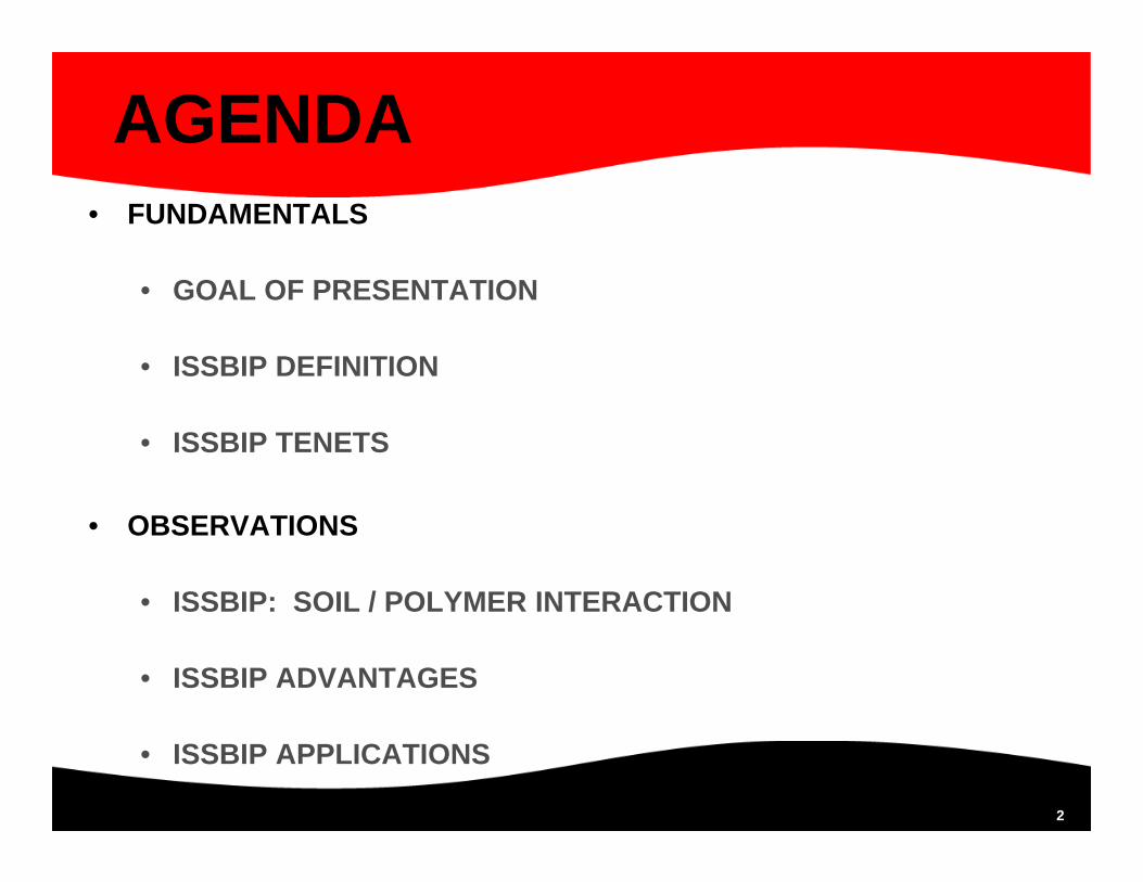
AGENDA• FUNDAMENTALS
• GOAL OF PRESENTATION
• ISSBIP DEFINITION
• ISSBIP TENETS
• OBSERVATIONS
• ISSBIP: SOIL / POLYMER INTERACTION
• ISSBIP ADVANTAGES
• ISSBIP APPLICATIONS
3
AGENDA (continued)
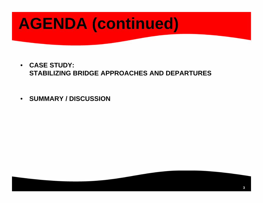
• CASE STUDY: STABILIZING BRIDGE APPROACHES AND DEPARTURES
• SUMMARY / DISCUSSION

4
FUNDAMENTALS
5
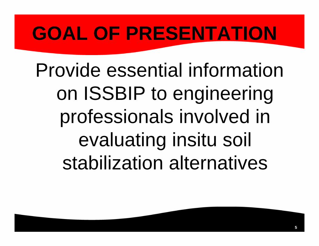
GOAL OF PRESENTATION
Provide essential information on ISSBIP to engineering professionals involved in
evaluating insitu soil stabilization alternatives

6
ISSBIP DEFINITION
A process for stabilizing weak and/or poorly compacted soils insituand leveling structures (including bridge approaches / departures) by injecting a specially-formulated polyurethane into the soils

7
ISSBIP DEFINITION• ISSBIP Polyurethane Description
• Low viscosity when introduced into the soil
• 2-component: Resin & Hardener (1:1 by volume)
• Exothermic chemical reaction between the two components creates CO2 gas which causes polymer expansion and creates pressure on the surrounding environment
• Formulated to resist water intrusion into the reaction
8
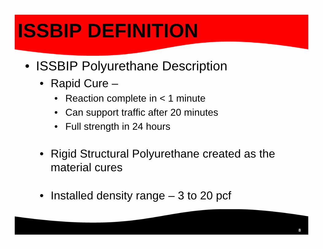
ISSBIP DEFINITION• ISSBIP Polyurethane Description
• Rapid Cure –• Reaction complete in < 1 minute• Can support traffic after 20 minutes• Full strength in 24 hours
• Rigid Structural Polyurethane created as the material cures
• Installed density range – 3 to 20 pcf

9
ISSBIP DEFINITION• ISSBIP Process Description
• The heated components are introduced in the impingement gun and forced down the injection tube by air pressure
• The low viscosity polymer flows easily into the voids and weak zones in the soil mass
• As the reaction occurs, the expanding polymer compacts the surrounding soils; continued injection yields lift
• Reaction mass necessary for compaction is achieved by 1) weight of pavement and overlying soil2) stabilized mass in the upper elevations by employing
a top-down injection pattern

10
ISSBIP TENETS• Polymer is placed via an injection tube; “surgically” placed in
the strata where stabilization is needed
• Multiple injection tubes are used to promote full coverage throughout the area being stabilized
• Injected substance is a two-component, high-density polyurethane characterized by rapid expansion and large volume increase created by chemical reaction between the components
• Movement is monitored at the surface during the injection process

11
OBSERVATIONS
12
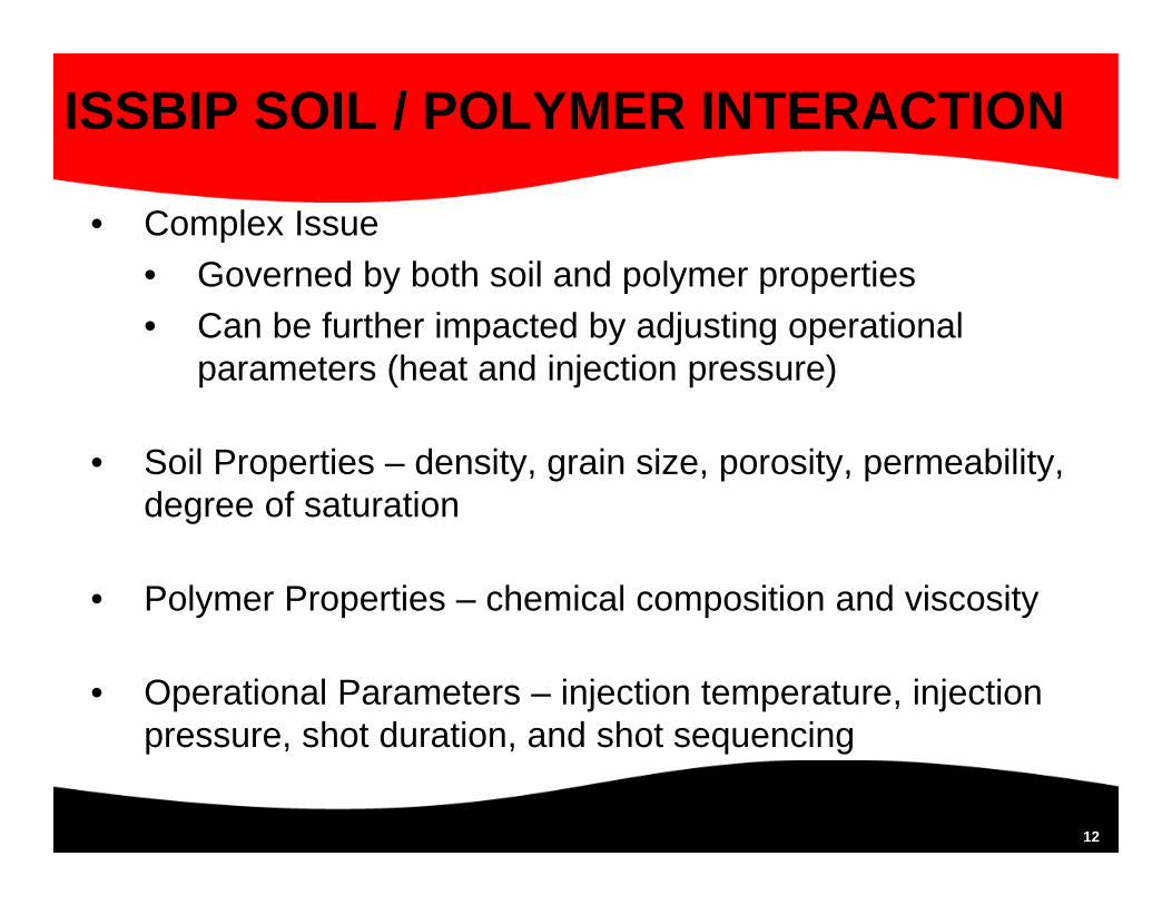
ISSBIP SOIL / POLYMER INTERACTION
• Complex Issue• Governed by both soil and polymer properties• Can be further impacted by adjusting operational
parameters (heat and injection pressure)
• Soil Properties – density, grain size, porosity, permeability, degree of saturation
• Polymer Properties – chemical composition and viscosity
• Operational Parameters – injection temperature, injection pressure, shot duration, and shot sequencing

13
ISSBIP SOIL / POLYMER INTERACTION – TRENDS
• Aggregate Bases/Subbases and Coarse Sand• Polymer Infiltration (binding)• Polymer Expansion (compacting)
• Saturated Fine Sands• Polymer expansion displaces the water and flowable soils• Polyurethane encapsulates the remaining soil and begins
to “set up”
14
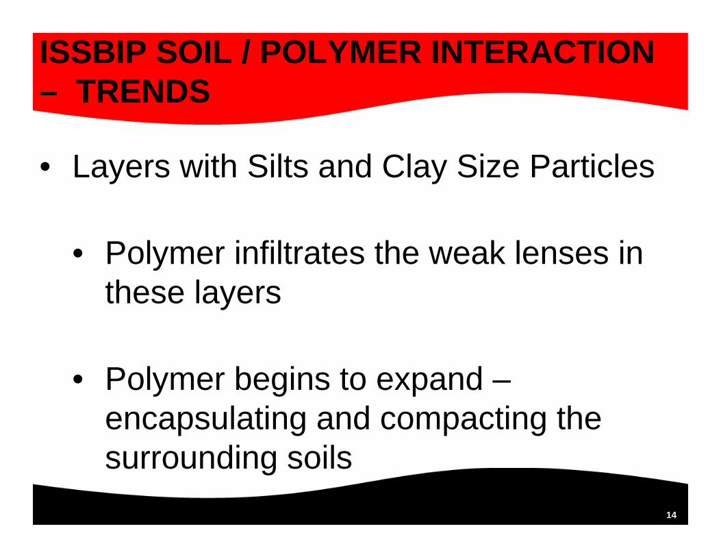
ISSBIP SOIL / POLYMER INTERACTION – TRENDS
• Layers with Silts and Clay Size Particles
• Polymer infiltrates the weak lenses in these layers
• Polymer begins to expand –encapsulating and compacting the surrounding soils

15
ISSBIP SOIL / POLYMER INTERACTION – TRENDS• Organic Soils
• When operating in soft soils, the polymer reaction time is accelerated so the polymer spends little time moving laterally
• The rapid reaction time causes the polyurethane to form a vertical shear wall within the soft soil mass
• By designing the injection pattern, these walls can be shaped into an interconnected series of confinement cells capable of supporting loads

16
ISSBIP SOIL / POLYMER INTERACTION – TRENDS
PHOTOGRAPHS

171717
Stabilization of Aggregate Subbase

181818
Excavation Revealing ISSBIP-Stabilized Sand

19
Excavating Native Soil to Expose Crater Repair – Note Polymer Veins

20
Intact Extraction of Stabilized Crater Repair

212121
Forensic Excavation of ISSBIP-StabilizedPeat Deposit
The constructed structure was removed to expose the injected foam
22
ISSBIP ADVANTAGES
• Fast: can withstand traffic in 20 minutes; achieves full strength within 24 hours
• Reduced Disruption: Minimally Invasive Process
• Predictable: Highly Controlled Expansion
• Accuracy: Precision Alignment of Faulted Slabs
23
ISSBIP ADVANTAGES
• Lightweight: Provides strength (with minimal weight) to the already distressed soil
• Great utility: a single process which can solve multiple problems
• Permanent: Impervious to Water and Most Chemicals
• Eco-Friendly: Environmentally Benign Material; NSF 61 Certified (can use around potable water)
24
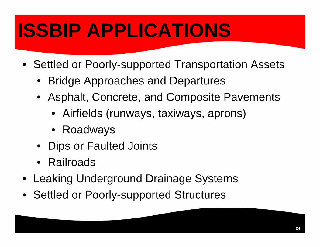
ISSBIP APPLICATIONS• Settled or Poorly-supported Transportation Assets
• Bridge Approaches and Departures• Asphalt, Concrete, and Composite Pavements
• Airfields (runways, taxiways, aprons)• Roadways
• Dips or Faulted Joints• Railroads
• Leaking Underground Drainage Systems• Settled or Poorly-supported Structures

25
CASE STUDYSTABILIZING BRIDGE APPROACHES AND
DEPARTURES

26
CASE STUDY – DESCRIPTION
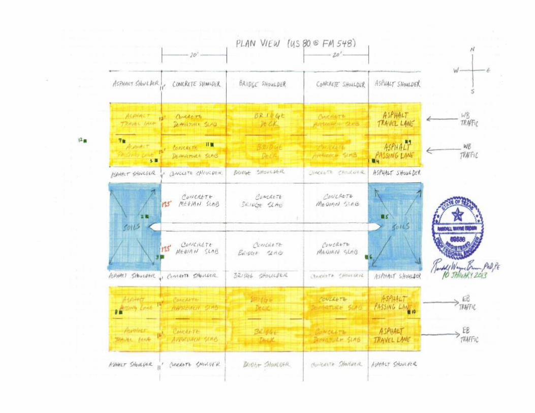
• STABILIZING SOILS ON BOTH THE EAST AND WEST ENDS OF A BRIDGE ON US 80 OVERPASSING FM 548
• FORNEY, TEXAS
• JANUARY 2013

27
CASE STUDY – DATA REVIEW
• PHOTOGRAPHS FROM SITE VISIT
• DCP RESULTS
• CONSULTANT’S GEOTECHNICAL REPORT AND SUPPLEMENT

28

29

30
31

32
33

34

35

36
CASE STUDY – FINDINGS
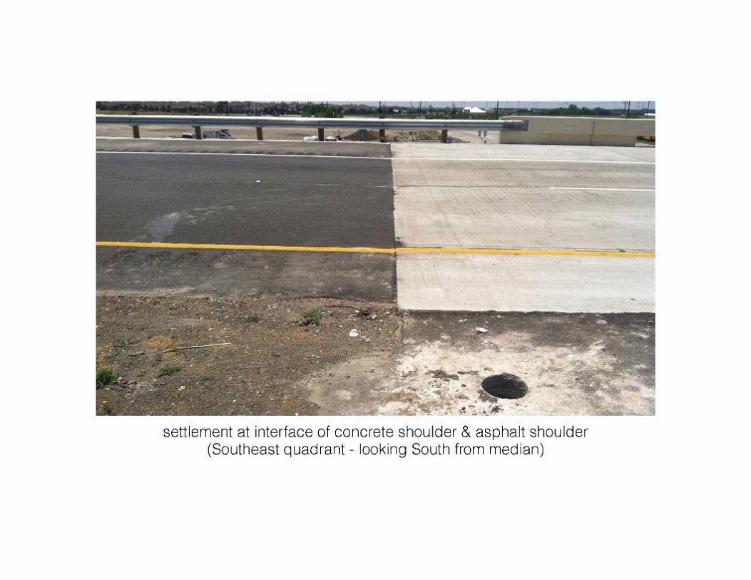
• NON-UNIFORM SLAB SUPPORT FOR THE APPROACH AND DEPARTURE SLABS LED TO SETTLEMENT
• MIGRATION OF FINES FROM THE COMPACTED SOIL ZONE INTO THE STONE ZONE RESULTED IN VOIDING, REDUCTION IN SUPPORT, AND DISTRESSES

37
CASE STUDY – FINDINGS
• CROSS-SLOPE and LONGITUDINAL SLOPE LED TO RUNOFF COLLECTING IN THE NW QUADRANT (WB DEPARTURE AREA) LEADING TO SATURATED CONDITIONS
• GEOTECHNICAL CONSULTANT FOUND SOIL UNDER WB LANES WAS WEAKER THAN UNDER EB LANES

38
CASE STUDY – FINDINGS
• GEOTECHNICAL CONSULTANT CONCLUDED THERE WAS CREEP DEFORMATION OF THE EMBANKMENT
• GEOTECHNICAL CONSULTANT SAID IT WAS “DIFFICULT TO ASCRIBE THE ACTUAL CAUSE OF PAVEMENT SETTLEMENT TO ANY ONE FACTOR IN THIS CASE”
39
CASE STUDY – TREATMENT
• ESTABLISHED A GROUT CURTAIN BETWEEN THE COMPACTED SOIL ZONE AND ROCK ZONE TO PRECLUDE THE MIGRATION OF FINES
• STABILIZED SUPPORT SOILS AND LIFTED SLABS THAT ARE EXHIBITING SETTLEMENT
40
CASE STUDY – TREATMENT
• STABILIZED SOILS SUPPORTING PAVEMENTS EXHIBITING DISTRESS
• STABILIZED THE ASPHALT SHOULDER PAVEMENT IN THE NW QUADRANT (WB DEPARTURE AREA) TO REDUCE WATER INFILTRATION INTO THE SUPPORT SOILS

41
CASE STUDY – TREATMENT
• STABILIZED THE BACKFILL SOILS IN THE RETAINED ZONE OF THE WB LANES (NW and NE QUADRANTS)
• INJECTION DEPTHS/ PATTERN VARIED BASED ON:• OBJECTIVE SOUGHT• SOIL CONDITIONS• MAGNITUDE OF DISTRESS
42
CASE STUDY – SUMMARY
• EXECUTED: 11-28 JANUARY 2013(16 days of actual injection)
• COST OF PROJECT: $190,349
• 2-YEAR WARRANTY; NO CALL BACKS IN YEAR ONE
• URETEK USA PERSONNEL PERFORMED A ROUTINE “ONE YEAR ANNIVERSARY” INSPECTION ON 4 FEBRUARY 2014

43
SUMMARY / DISCUSSION
44
ISSBIP SUMMARY• Fixes the problem by stabilizing the soils and
increasing the stiffness of the weak layers in order to better support the load
• Fixes the symptom of the problem by lifting the settled pavement or structure to the desired grade
• Completed with minimal downtime
45
THANK YOU FOR
YOUR TIME

46
MICHIGAN CONTACTS• Brian C. Shutts
• [email protected]• 269-208-5648 Phone
• Brian Francis• [email protected]• 313-300-5888 Phone
47
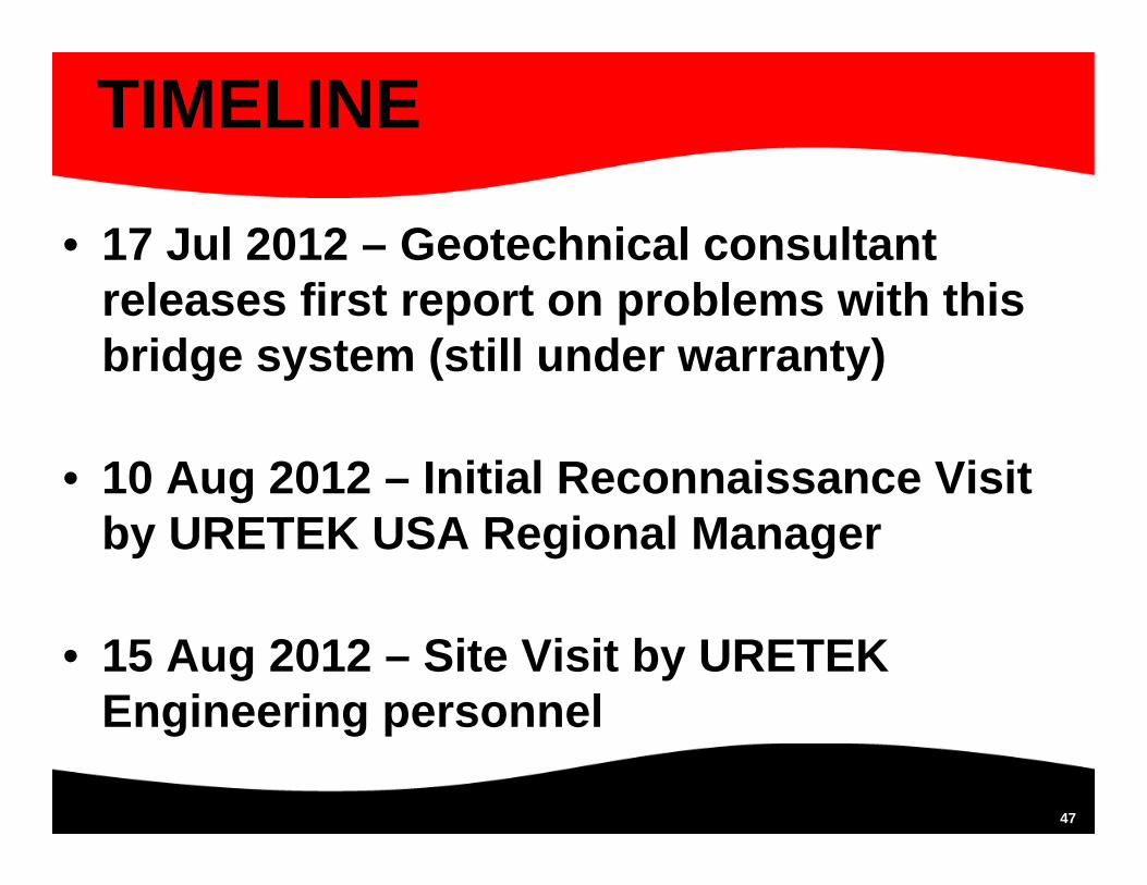
TIMELINE
• 17 Jul 2012 – Geotechnical consultant releases first report on problems with this bridge system (still under warranty)
• 10 Aug 2012 – Initial Reconnaissance Visit by URETEK USA Regional Manager
• 15 Aug 2012 – Site Visit by URETEK Engineering personnel

48
TIMELINE
• 20 Aug 2012 – Initial Remediation Plan and Proposal published by URETEK USA
• 5 Sep 2012 – Geotechnical consultant publishes supplemental report
• 23 Sep 2012 – Supplement to Remediation Plan published by URETEK USA
49
TIMELINE
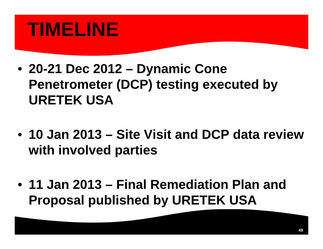
• 20-21 Dec 2012 – Dynamic Cone Penetrometer (DCP) testing executed by URETEK USA
• 10 Jan 2013 – Site Visit and DCP data review with involved parties
• 11 Jan 2013 – Final Remediation Plan and Proposal published by URETEK USA

50
TIMELINE
• 11- 28 Jan 2013 – Stabilization of Soils in the Bridge System using ISSBIP(16 actual injection days within this timeframe)
• 4 Feb 2013 – Inspection by URETEK USA personnel (1-year anniversary)