paxton automotive novi 1000 supercharger 2001-2003 4.6l sohc
TRANSCRIPT

DP/N: 4809628 - V2.1 06/05/03
Owner’s Installation Guide for the
Paxton AutomotiveNovi 1000 Supercharger
for the
2001-2003 4.6L SOHC Mustang GTPaxton Automotive . 1300 Beacon Place . Oxnard CA 93033
805 604-1336 . FAX (805) 604-1337
P/N: 4809628©2003 Paxton AutomotiveAll Rights Reserved, Intl. Copr. Secured05JUN03 v2.1 MusGT(4809628 v2.1)
ii
FOREWORD
Before you start the installation of your supercharger Paxton superchargerkit, you will have to find the Paxton Computer Chip Voucher located inyour information packet. The 2001-2003 Mustang GT Supercharger Kitrequires a computer chip upgrade. You will need to fill out the chip vouch-er and send it and your computer to Paxton Automotive to receive yourchip upgrade. Please refer to section 7 of this manual for the procedure forremoving your engine control module.
Complete the Paxton Automotive/Ford Computer Chip Voucher andreturn it to Paxton Automotive to receive the proper computer module foryour vehicle.
© 2003 PAXTON AUTOMOTIVEAll rights recerved. No parts of this publication may be reproduced, transmitted, transcrived, or translated into
another language in any form, by any means without written permission of Paxton Automotive.
P/N: 4809628©2003 Paxton Automotive
All Rights Reserved, Intl. Copr. Secured05JUN03 v2.1 MusGT(4809628 v2.1)
iii
TABLE OF CONTENTS
FOREWORD . . . . . . . . . . . . . . . . . . . . . . . . . . . . . . . . . . . . . . . . . . . . . . . . . . . . . . . . . . . . . . . . . . . . .iiTABLE OF CONTENTS . . . . . . . . . . . . . . . . . . . . . . . . . . . . . . . . . . . . . . . . . . . . . . . . . . . . . . . . . . . .iiiIMPORTANT NOTES . . . . . . . . . . . . . . . . . . . . . . . . . . . . . . . . . . . . . . . . . . . . . . . . . . . . . . . . . . . . . .iv1.1 INITIAL PREPARATION AND REMOVAL . . . . . . . . . . . . . . . . . . . . . . . . . . . . . . . . . . . . . .1-12.1 SUPERCHARGER MOUNTING BRACKET ATTACHMEMT . . . . . . . . . . . . . . . . . . . . . . . .2-13.1 FAN RESISTOR RELOCATION . . . . . . . . . . . . . . . . . . . . . . . . . . . . . . . . . . . . . . . . . . . . . . . .3-14.1 PREPARING TO MOUNT THE SUPERCHARGER . . . . . . . . . . . . . . . . . . . . . . . . . . . . . . . . .4-15.1 OIL FEED AND DRAIN LINES . . . . . . . . . . . . . . . . . . . . . . . . . . . . . . . . . . . . . . . . . . . . . . . .5-16.1 INTAKE TRACT MODIFICATIONS . . . . . . . . . . . . . . . . . . . . . . . . . . . . . . . . . . . . . . . . . . . .6-17.1 ENGINE CONTROL COMPUTER REMOVAL AND MODIFICATION . . . . . . . . . . . . . . . . .7-18.1 IN-TANK FUEL PUMP INSTALLATION . . . . . . . . . . . . . . . . . . . . . . . . . . . . . . . . . . . . . . . . .8-19.1 FINAL ASSEMBLY AND CHECK . . . . . . . . . . . . . . . . . . . . . . . . . . . . . . . . . . . . . . . . . . . . . .9-1APPENDIX . . . . . . . . . . . . . . . . . . . . . . . . . . . . . . . . . . . . . . . . . . . . . . . . . . . . . . . . . . . . . . . . . . . . . .A-1
List of Appendices . . . . . . . . . . . . . . . . . . . . . . . . . . . . . . . . . . . . . . . . . . . . . . . . . .A-2Appendix A 1011816 ASY, S/C NOVI 1000 . . . . . . . . . . . . . . . . . . . . . . . . . . . . . . . . .A-3Appendix B 1015309 ASY, RADIATOR HOSE MODIFICATION . . . . . . . . . . . . . . . .A-4Appendix C 1016630 ASY, S/C MOUNTING BRACKET . . . . . . . . . . . . . . . . . . . . . .A-5Appendix D 1015933 ASY, AIR INTAKE . . . . . . . . . . . . . . . . . . . . . . . . . . . . . . . . . . .A-6Appendix E 1017017 ASY, AIR DISCHARGE . . . . . . . . . . . . . . . . . . . . . . . . . . . . . . .A-7Appendix F 1019336 ASY, OIL SUPPLY . . . . . . . . . . . . . . . . . . . . . . . . . . . . . . . . . . .A-8Appendix G 1019328 ASY, OIL RETURN . . . . . . . . . . . . . . . . . . . . . . . . . . . . . . . . . .A-9Appendix H 1015506 ASY, COMPRESSOR BYPASS . . . . . . . . . . . . . . . . . . . . . . . . .A-10Appendix I 1015530 ASY, FAN RESISTOR RELOC. . . . . . . . . . . . . . . . . . . . . . . . .A-11Appendix J 1017734 ASY, FUEL PUMP . . . . . . . . . . . . . . . . . . . . . . . . . . . . . . . . . .A-12Appendix K 7000170 DIAGRAM, BELT ROUTING . . . . . . . . . . . . . . . . . . . . . . . . . .A-13
P/N: 4809628©2003 Paxton AutomotiveAll Rights Reserved, Intl. Copr. Secured05JUN03 v2.1 MusGT(4809628 v2.1)
iv
IMPORTANT NOTES
Congratulations! You have purchased thefinest street supercharger available for theMustang GT. The centerpiece of this kit is
the High Efficiency PAXTON Supercharger, amechanically driven centrifugal blower.
This kit comes with all the parts you will need toinstall the supercharger. The instruction manual hasbeen edited in order of sequence, and photographsand drawings have been included to illustrate thetext. This will allow you quick part identificationand orientation.
The installation will require metric and SAE sock-ets and wrenches, a hand drill and bits, an AirHammer (and compressor), a 3/8” x 18 NPT tap,screwdrivers, and a supply of buckets for thereserve of coolant and oils.
We suggest that you obtain a copy of a Mustangshop manual for your model of car. This may beobtained from your dealer, or may be ordered by
mail from Helm Publications at (800) 782-4356.Become familiar with the details of your car’s sys-tem. If it is not operating within normal parame-ters, we do not recommend the installation or useof the supercharger.
For the quickest installation time, we suggest thatyou read this manual thoroughly before beginning.Make sure that you understand the process, haveidentified the areas of the car that you will beworking on, and have the tools that you will needon hand. The average installation time is 8 to 10hours, but your time will depend on your workingconditions, experience installing superchargers,personal skill level, and preparedness for the job.This estimate does not include time for the initialvehicle inspection, cleaning, fine tuning, or trou-ble-shooting. Once again, we recommend readingthe manual before beginning the process. We areavailable for tech support at (805) 604-1336,Monday through Friday, 7AM - 3 PM PST.
After reading the manual, verify that all major assembly groups are present in the main kit box. As youremove a box or bag, note the identification label and compare it to the parts list.
PAXTON AUTOMOTIVE makes every effort to insurethat all parts are included in the box. If you
discover that you are missing any part, or that a part was damaged in shipping, call PAXTON
immediately. DO NOT begin installation if a part is missing. Failure to contact PAXTON prior tobeginning installation will result in a charge for
the missing part.
We suggest that the engine compartment becleaned before the installation. You can clean theengine with a pressure washer that is found at self-
serve car washes. Use a safe-for-aluminum clean-er/degreaser, and cover the distributor and anyelectronics with a plastic bag to prevent water fromentering.

P/N: 4809628©2003 Paxton Automotive
All Rights Reserved, Intl. Copr. Secured05JUN03 v2.1 MusGT(4809628 v2.1)
v
You are undoubtedly eager to get started, butplease take a little more time to insure thatyour safety is not in jeopardy. A moment’s
lack of attention may cause a serious injury to you,or to someone else who happens to be standingaround. By following some simple safety precau-
PAXTON Automotive thanks you for your purchase. We welcome yourcomments and suggestions to help us improve our product.
tions, you can avoid many potential dangers. Thefollowing list is not meant to be a comprehensivelist, but rather it is meant to make you aware ofsome of the risks, and encourage you to take asafety minded approach to your work area.
• Never rely solely on a floor jack when working under-neath a vehicle. Always use jack stands that are ratedfor the weight of your vehicle, use them at the recom-mended lift points, and place your vehicle in ‘PARK’ or‘FIRST’ gear with the parking brake set.
• Always use eye protection when using power tools, suchas drills, saws, and grinders, or when working under-neath a vehicle.
• Never smoke, use an open flame, or have spark produc-ing items around gasoline or flammable objects. Alwayshave a fire extinguisher that is rated for chemical andelectrical fires handy when working on motor vehicles.Also, make sure that the extinguisher is fully charged.
• Operate engines only in a well ventilated area. CarbonMonoxide, gasoline, and solvent vapors are colorlessand sometimes odorless, and may asphyxiate andexplode without warning.
• Always disconnect the battery from your engine beforedoing work on the electrical or fuel systems, or doingunderdash work.
• The chemicals used in the vehicle systems, such as oilsand coolants, are poisonous. Clean up any spills imme-diately, and dispose of waste materials properly. Pets,wild animals, and children may die if they ingest the liq-uid.

P/N: 4809628©2003 Paxton AutomotiveAll Rights Reserved, Intl. Copr. Secured05JUN03 v2.1 MusGT(4809628 v2.1)
vi
This Page Left Intentionally Blank.

1-1P/N: 4809628
©2003 Paxton AutomotiveAll Rights Reserved, Intl. Copr. Secured
05JUN03 v2.1 MusGT(4809628 v2.1)
Section 1INITIAL PREPARATION AND REMOVAL
B. Before the air intake assembly can beremoved, you must first disconnect the plas-tic crankcase breather hose (A) and air idlebypass hose (B). Unplug the air temperaturesensor (C) and mass air flow sensor (D).(See Fig. 1-a.)
***NOTE***(2002-2003 GT only) The air intake temperature sen-sor is now located in the MAF. (Step “C” no longerapplies.)
Fig. 1-a
A
B
C
D
1.1 INITIAL PREPARATION AND REMOVAL
A. Begin the initial preparation and disassem-bly process by first disconnecting the nega-tive side of the battery, and draining one gal-lon of coolant from the coolant reservoir. Todo this, open the valve at the bottom of theradiator and allow to drain into a suitablecontainer. DO NOT allow coolant to drainonto floor, and be sure to mop up anycoolant splatter immediately. Animals likethe taste of coolant, and if they drink it, itwill kill them.

1-2P/N: 4809628©2003 Paxton AutomotiveAll Rights Reserved, Intl. Copr. Secured05JUN03 v2.1 MusGT(4809628 v2.1)
Fig. 1-b
Fig. 1-c
E. Once the assembly is out of the car, use a10mm socket to remove the mass air flowsensor and screen from the air filter housing(see Fig 1-d). Place the mass air flow sensoraside to be re-installed in a later step.
C. Using a flat-head screwdriver, loosen thehose clamps at the mass air flow sensor andthe throttle body, and remove the air intakehose (see Fig 1-b). Remove the air tempera-ture sensor from the air intake hose andplace it aside—it will be re-installed in alater step.
NOTE: On 2002-2003 GTs this step will not bedone.
D. Use an 8mm socket to remove the single airfilter housing retaining bolt. The air filterand mass air sensor can then be removed asan assembly. (See Fig 1-c.)
Fig. 1-d
E. The coolant reservoir is secured by threenuts (see Fig 1-e). Use a 10mm socket toremove these, and place the reservoir aside.Remove the upper radiator hose.
Fig. 1-e

2-1P/N: 4809628
©2003 Paxton AutomotiveAll Rights Reserved, Intl. Copr. Secured
05JUN03 v2.1 MusGT(4809628 v2.1)
Section 2SUPERCHARGER MOUNTING BRACKET ATTACHMENT
2.1 SUPERCHARGER MOUNTING BRACKET ATTACHMENT
Fig. 2-a
A. Loosen (but do not remove) the four 10 mmhead bolts securing the water pump pulley.Next, remove the accessory drive belt usinga 3/8-inch drive ratchet or breaker bar intothe square at the end of the tensioner, androtate the tensioner clockwise. This willrelieve the tension on the belt so it can beremoved. It will not be re-used. (See Fig. 2-a.)
B. Use a 13 mm socket to remove the idler pul-ley, located above the belt tensioner (see Fig2-b). Place the pulley aside to be used in alater step. Now, you may finish removingthe four 10mm bolts securing the waterpump pulley, and place the pulley and itsfasteners aside for use in a later step.
IDLER PULLEY
Fig. 2-b
C. Next, remove three bolts at the front of theengine (see Fig 2-c). A 10mm alternatormounting bolt (A), and two 13 mm timingcover bolts (B and C).
Fig. 2-c
C
B
A
2-2P/N: 4809628©2003 Paxton AutomotiveAll Rights Reserved, Intl. Copr. Secured05JUN03 v2.1 MusGT(4809628 v2.1)
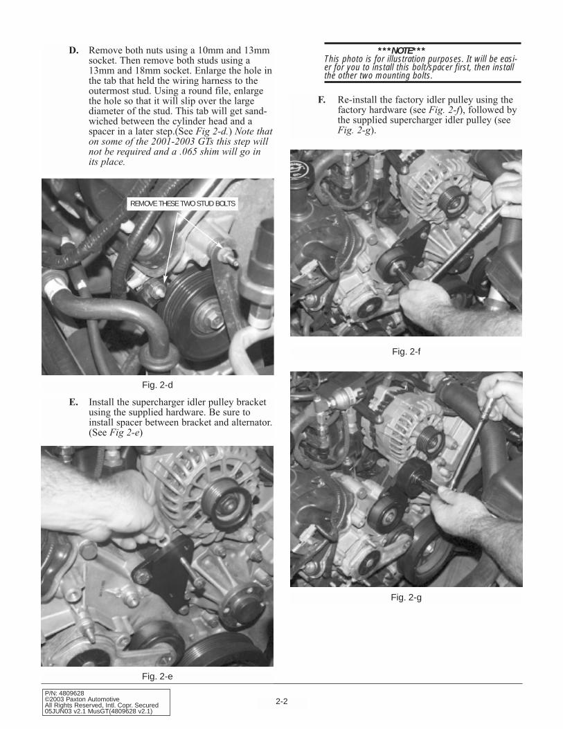
D. Remove both nuts using a 10mm and 13mmsocket. Then remove both studs using a13mm and 18mm socket. Enlarge the hole inthe tab that held the wiring harness to theoutermost stud. Using a round file, enlargethe hole so that it will slip over the largediameter of the stud. This tab will get sand-wiched between the cylinder head and aspacer in a later step.(See Fig 2-d.) Note thaton some of the 2001-2003 GTs this step willnot be required and a .065 shim will go inits place.
REMOVE THESE TWO STUD BOLTS
Fig. 2-d
E. Install the supercharger idler pulley bracketusing the supplied hardware. Be sure toinstall spacer between bracket and alternator.(See Fig 2-e)
Fig. 2-e
***NOTE***This photo is for illustration purposes. It will be easi-er for you to install this bolt/spacer first, then installthe other two mounting bolts.
F. Re-install the factory idler pulley using thefactory hardware (see Fig. 2-f), followed bythe supplied supercharger idler pulley (seeFig. 2-g).
Fig. 2-f
Fig. 2-g

2-3P/N: 4809628
©2003 Paxton AutomotiveAll Rights Reserved, Intl. Copr. Secured
05JUN03 v2.1 MusGT(4809628 v2.1)
G. Install the supercharger rear support bracketas shown in Fig 2-h. Temporarily install thelong 10mm bolt to line up the bracket.Leave the bolts finger tight, as it will benecessary to move the bracket when youinstall the main supercharger bracket.(This photo is for illustration only. You willhave to install the supercharger and acces-sory belt before installing the bracket. Therewon’t be clearance after the bracket isinstalled.)
Fig. 2-h
Fig. 2-i
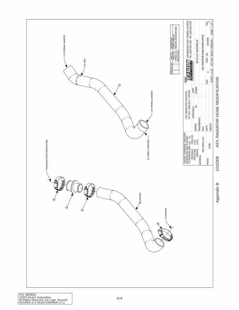
H. Modify the previously removed upper radia-tor hose with supplied hose, aluminum cou-pler and clamps. See Appendix ‘B’(1015309) for diagram of modification.
***NOTE***The radiator hose assembly needs to clear the super-charger, so it is better to leave it long and trim theassembly later than to end up short. The finishedradiator assembly is shown in Fig. 2-i.
I. Before installing the main superchargerbracket, the A/C refrigerant refilling portmust be bent from its upright position down-ward, so that the cap is facing the driver’sside fender. (See Fig 2-j.)
Fig. 2-j
***NOTE***If possible, use a proper tubing bender for this step.If one is not available, the line can be bent by hand,but extreme care must be taken as the refrigerantwithin the line is under very high pressure. In anycase, use a pair of heavy gloves and eye protection toprevent injury in the event of a ruptured line.

2-4P/N: 4809628©2003 Paxton AutomotiveAll Rights Reserved, Intl. Copr. Secured05JUN03 v2.1 MusGT(4809628 v2.1)
This Page Left Intentionally Blank.

3-1P/N: 4809628
©2003 Paxton AutomotiveAll Rights Reserved, Intl. Copr. Secured
05JUN03 v2.1 MusGT(4809628 v2.1)
Section 3FAN RESISTOR RELOCATION
3.1 FAN RESISTOR RELOCATION
A. Disconnect the wiring harness from the fanresistor. (See Fig. 3-a.) Remove clips hold-ing the fan resistor to the fan shroud. Attachthe fan resistor to the supplied bracket usingthe supplied hardware.
Fig. 3-a
B. Trim the fan resistor mounting tabs on thefan shroud to provide clearance for the airintake assembly.(See Fig. 3-b.) The fanshroud should look like this after trim-ming.(See Fig. 3-c.)
Fig. 3-b
Fig. 3-c
C. Re-attach the fan resistor to the wiring har-ness to ensure adequate wire length. (SeeFig. 3-d.) Position the fan bracket on thepassenger side of the lower fan shroud.Mark two mounting points along the fanshroud and drill the holes. Attach the mount-ing bracket with the supplied hardware.
Fig. 3-d

3-2P/N: 4809628©2003 Paxton AutomotiveAll Rights Reserved, Intl. Copr. Secured05JUN03 v2.1 MusGT(4809628 v2.1)
This Page Left Intentionally Blank.
4-1P/N: 4809628
©2003 Paxton AutomotiveAll Rights Reserved, Intl. Copr. Secured
05JUN03 v2.1 MusGT(4809628 v2.1)
Section 4PREPARING TO MOUNT THE SUPERCHARGER
A. Mount the main supercharger bracket,installing the two 3/8 bolts and spacers inthe upper portion of the bracket. Install thelong 6mm bolt and spacer in the lower mid-dle portion of the bracket, sandwiching theA/C support between the spacer and rearmounting bracket. Next, install the lowermost bolt and two spacers: one in betweenthe support and main brackets, one inbetween the two brackets and the otherbetween the rear bracket and the cylinderhead. The small metal tab securing thewiring harness gets sandwiched between thecylinder head and the spacer. Leave every-thing finger tight at this point.
***NOTE***The drive belt, shown in this picture, should beinstalled at this point.(See Fig. 4-a.)
4.1 PREPARING TO MOUNT THE SUPERCHARGER
Fig. 4-a
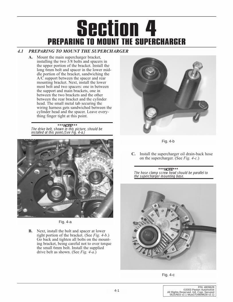
B. Next, install the bolt and spacer at lowerright portion of the bracket. (See Fig. 4-b.)Go back and tighten all bolts on the mount-ing bracket, being careful not to over torquethe small 6mm bolt. Install the supplieddrive belt as shown. (See Fig. 4-a.)
Fig. 4-b
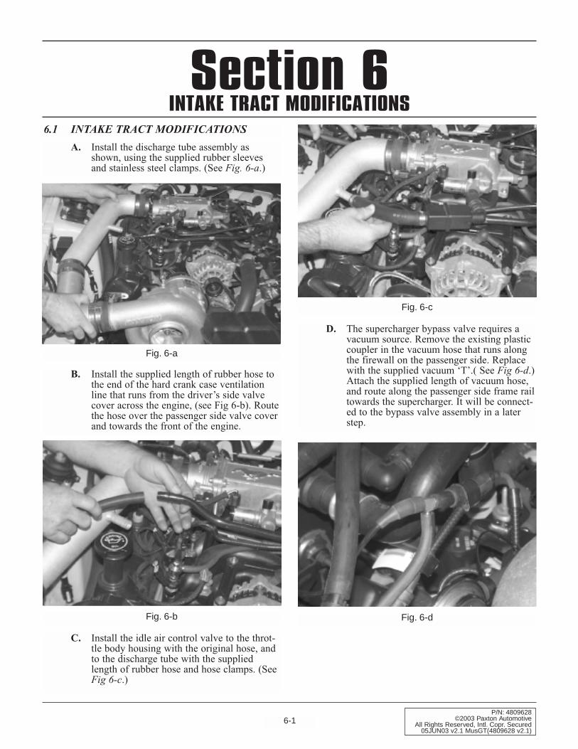
C. Install the supercharger oil drain-back hoseon the supercharger. (See Fig. 4-c.)
***NOTE***The hose clamp screw head should be parallel tothe supercharger mounting base.
Fig. 4-c

4-2P/N: 4809628©2003 Paxton AutomotiveAll Rights Reserved, Intl. Copr. Secured05JUN03 v2.1 MusGT(4809628 v2.1)
D. Remove the drive belt from the alternatorpulley. Install the supercharger into the mainbracket, while looping the drive belt aroundthe supercharger pulley. (See Fig. 4-d.)
Fig. 4-d
E. Tighten the supercharger mounting bolts.Once the supercharger is installed, releasethe belt tensioner and loop the belt backaround the alternator pulley. (SeeAppendix K for a diagram of the drive beltrouting.)
***NOTE***For maximum performance, PAXTON Automotive rec-ommends the factory stock platinum spark plugs bereplaced with a copper spark plug (Autolite 764 orequivalent) gapped to .035.
F. Remove the two 8mm bolts on either end ofthe Fuel Injector Rail and lift the unit out.Replace the stock injectors with the suppliedinjectors. Use white lithium grease on the O-rings to insure a smooth fit.
Fig. 4-e

5-1P/N: 4809628
©2003 Paxton AutomotiveAll Rights Reserved, Intl. Copr. Secured
05JUN03 v2.1 MusGT(4809628 v2.1)
Section 5OIL FEED AND DRAIN LINES
5.1 OIL FEED AND DRAIN LINES
A. Your Paxton Automotive NOVI 1000 super-charger uses pressurized engine oil for lubri-cation. Use an oil sending unit socket (Snap-On tools; part number 6152 or equivalent) toremove the oil sending unit on the undersideof the oil filter housing (see Fig 5-a). Installthe supplied brass junction fitting using asmall amount of Teflon paste. DO NOTUSE TEFLON TAPE. Once installed, thejunction fitting should be oriented so thatthe opening faces toward the front of the car.
Fig. 5-a
B. Install the oil sending unit in the end of thebrass junction. Install the 90 degree 1/8-inchto -4 fitting into the side of the brass junc-tion, and orient this fitting to face towardsthe driver’s side frame rail. Attach the sup-plied length of braided stainless steel feedline, and route upwards to the 90 degree fit-ting on the supercharger.
***NOTE***Be sure to stay clear of any moving parts or coolanthoses (engine vibration can cause the stainless lineto chafe the rubber coolant hose, creating a leak overtime). Install the line, and tighten moderately—nosealant is required. (See Fig. 5-b.)
Fig. 5-b
C. Mark the front of the oil pan 1" inch belowthe pan rail and between the the two pan railbolts, directly in the center of the small‘hump’. (See Appendix G.) Cover a 3/16-inch drill bit with heavy grease and drill apilot hole (see Fig. 5-c). The grease willhelp prevent metal particles from falling intothe pan. Once the hole has been drilled,insert a straight length of welding rod orheavy wire (such as a coat hanger) into thehole approximately three inches to makesure no interference is encountered. If thepath is blocked, turn the engine over untilthe pathway is clear.
Fig. 5-c

5-2P/N: 4809628©2003 Paxton AutomotiveAll Rights Reserved, Intl. Copr. Secured05JUN03 v2.1 MusGT(4809628 v2.1)
D. Next, apply a small amount of anti-seizelubricant to the tip of the punch, and insert itinto the pilot hole. Hit the punch with an airhammer carefully using small bursts, untilthe punch is inserted up to its shoulder. Thehole should measure 9/16". (See Fig 5-d.)
NO DEEPER THAN THIS
Fig. 5-d
***NOTE***Do not use hand tools. Using an ordinary hammerwill dent the pan. Use extreme caution not to makethe hole to big, or the drain fitting will not fit and thepan will be ruined.
E. Apply a liberal amount of heavy grease to a3/8 inch x 16 NPT tap (not included), andgradually thread into the hole. Clean thethreads using a clean rag and an approvedsolvent, such as carburetor cleaner.
F. Apply a ample amount of silicone RTV tothe threads of the supplied 3/8-inch pipe to -8 fitting and insert into the hole, being care-ful not to over-tighten. (See Fig. 5-e.)
Fig. 5-e
G. Install the supercharger drain-back hose fit-ting so that the elbow is oriented toward thepassenger side, away from the harmonic bal-ancer/crank pulley.(See Fig 5-f.)
Fig. 5-f
6-1P/N: 4809628
©2003 Paxton AutomotiveAll Rights Reserved, Intl. Copr. Secured
05JUN03 v2.1 MusGT(4809628 v2.1)
Section 6INTAKE TRACT MODIFICATIONS
6.1 INTAKE TRACT MODIFICATIONS
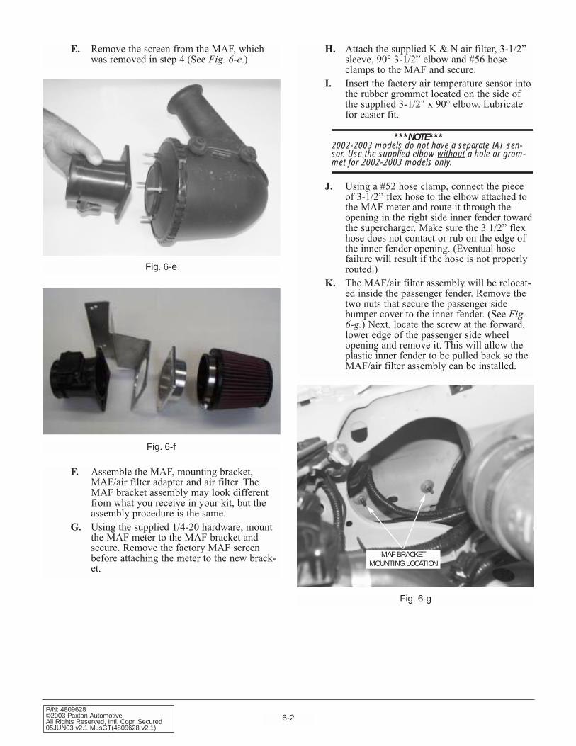
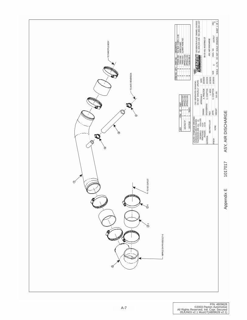
A. Install the discharge tube assembly asshown, using the supplied rubber sleevesand stainless steel clamps. (See Fig. 6-a.)
Fig. 6-a
B. Install the supplied length of rubber hose tothe end of the hard crank case ventilationline that runs from the driver’s side valvecover across the engine, (see Fig 6-b). Routethe hose over the passenger side valve coverand towards the front of the engine.
Fig. 6-b
C. Install the idle air control valve to the throt-tle body housing with the original hose, andto the discharge tube with the suppliedlength of rubber hose and hose clamps. (SeeFig 6-c.)
Fig. 6-c
D. The supercharger bypass valve requires avacuum source. Remove the existing plasticcoupler in the vacuum hose that runs alongthe firewall on the passenger side. Replacewith the supplied vacuum ‘T’.( See Fig 6-d.)Attach the supplied length of vacuum hose,and route along the passenger side frame railtowards the supercharger. It will be connect-ed to the bypass valve assembly in a laterstep.
Fig. 6-d
6-2P/N: 4809628©2003 Paxton AutomotiveAll Rights Reserved, Intl. Copr. Secured05JUN03 v2.1 MusGT(4809628 v2.1)
E. Remove the screen from the MAF, whichwas removed in step 4.(See Fig. 6-e.)
Fig. 6-e
F. Assemble the MAF, mounting bracket,MAF/air filter adapter and air filter. TheMAF bracket assembly may look differentfrom what you receive in your kit, but theassembly procedure is the same.
G. Using the supplied 1/4-20 hardware, mountthe MAF meter to the MAF bracket andsecure. Remove the factory MAF screenbefore attaching the meter to the new brack-et.
Fig. 6-f
Fig. 6-g
H. Attach the supplied K & N air filter, 3-1/2”sleeve, 90° 3-1/2” elbow and #56 hoseclamps to the MAF and secure.
I. Insert the factory air temperature sensor intothe rubber grommet located on the side ofthe supplied 3-1/2" x 90° elbow. Lubricatefor easier fit.
***NOTE***2002-2003 models do not have a separate IAT sen-sor. Use the supplied elbow without a hole or grom-met for 2002-2003 models only.
J. Using a #52 hose clamp, connect the pieceof 3-1/2” flex hose to the elbow attached tothe MAF meter and route it through theopening in the right side inner fender towardthe supercharger. Make sure the 3 1/2” flexhose does not contact or rub on the edge ofthe inner fender opening. (Eventual hosefailure will result if the hose is not properlyrouted.)
K. The MAF/air filter assembly will be relocat-ed inside the passenger fender. Remove thetwo nuts that secure the passenger sidebumper cover to the inner fender. (See Fig. 6-g.) Next, locate the screw at the forward,lower edge of the passenger side wheelopening and remove it. This will allow theplastic inner fender to be pulled back so theMAF/air filter assembly can be installed.
MAF BRACKET MOUNTING LOCATION

6-3P/N: 4809628
©2003 Paxton AutomotiveAll Rights Reserved, Intl. Copr. Secured
05JUN03 v2.1 MusGT(4809628 v2.1)
Fig. 6-h
L. Place the MAF/air filter bracket over theexisting studs, then secure with the originalnuts. (See Fig. 6-h.)
M. Carefully open the main wiring harness(runs from the passenger side inner fenderinto the engine compartment) with a razorblade, making an incision that is approxi-mately 6-inches long. Pull the MAF wiringupwards, until the wires are long enough tobe routed back through the opening in theinner fender, and down to the MAF. (SeeFig. 6-i.)
Fig. 6-i
P. Connect the plastic inlet duct (with bypassvalve and hoses attached) to the supercharg-er inlet. This is to illustrates what the MAFassembly should look like after assembly.(See Fig. 6-k.)
FRONT
INSIDERIGHT FRONTPASSENGERFENDERWELL
#56 CLAMPS
FACTORY AIRTEMPERATURE SENSOR
(NOT ON 2002+ MODELS)
3-1/2" ELBOW
SLEEVE
FACTORYSTUDS & NUTS
Fig. 6-k
N. Insert the 1" x 10" rubber hose to the inlet ofthe compressor bypass valve. Secure bothhoses with the supplied #16 hose clamps.
O. Install the bypass valve assembly on theunderside of the secondary intake tube. (SeeFig. 6-j.) Tighten the hose clamp to securethe valve assembly to the intake tube.
Fig. 6-j
6-4P/N: 4809628©2003 Paxton AutomotiveAll Rights Reserved, Intl. Copr. Secured05JUN03 v2.1 MusGT(4809628 v2.1)
Fig. 6-l
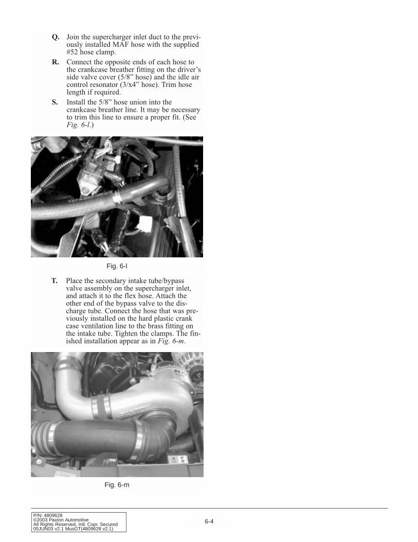
T. Place the secondary intake tube/bypassvalve assembly on the supercharger inlet,and attach it to the flex hose. Attach theother end of the bypass valve to the dis-charge tube. Connect the hose that was pre-viously installed on the hard plastic crankcase ventilation line to the brass fitting onthe intake tube. Tighten the clamps. The fin-ished installation appear as in Fig. 6-m.
Fig. 6-m
Q. Join the supercharger inlet duct to the previ-ously installed MAF hose with the supplied#52 hose clamp.
R. Connect the opposite ends of each hose tothe crankcase breather fitting on the driver’sside valve cover (5/8” hose) and the idle aircontrol resonator (3/x4” hose). Trim hoselength if required.
S. Install the 5/8” hose union into thecrankcase breather line. It may be necessaryto trim this line to ensure a proper fit. (SeeFig. 6-l.)

7-1P/N: 4809628
©2003 Paxton AutomotiveAll Rights Reserved, Intl. Copr. Secured
05JUN03 v2.1 MusGT(4809628 v2.1)
Fig. 7-a
Section 7ENGINE CONTROL COMPUTER REMOVAL AND MODIFICATION
7.1 ENGINE CONTROL COMPUTERREMOVAL AND MODIFICATION
B. Pull the harnesses down and out of the way,creating unobstructed access to the comput-er. Remove the 7/32 screw that secures theretention strap (see Fig. 7-b) and pull thecomputer out of the foot well.(see Fig. 7-c.)
A. Remove the passenger side door sill plate,followed by the passenger side kick panel.This will reveal the engine control computerand its harnesses. The harnesses are securedusing clips, which are attached to a smallmetal bracket. Pull the harnesses off thebracket, then remove the two 7/32-inch boltsthat secure the bracket itself. Remove thebracket.(See Fig. 7-a.)
Fig. 7-b
Fig. 7-c

7-2P/N: 4809628©2003 Paxton AutomotiveAll Rights Reserved, Intl. Copr. Secured05JUN03 v2.1 MusGT(4809628 v2.1)
D. Remove the 10mm bolt that secures themain harness to the computer, and removethe harness. (See Fig. 7-d.)
E. Once the computer is removed from the car,you will need to send your computer and thechip voucher to Paxton Automotive. Thecomputer will be cleaned, a computer chipinstalled and returned to you, ready to beinstall back into your vehicle.
Fig. 7-d
8-1P/N: 4809628
©2003 Paxton AutomotiveAll Rights Reserved, Intl. Copr. Secured
05JUN03 v2.1 MusGT(4809628 v2.1)
Section 8IN-TANK FUEL PUMP INSTALLATION
8.1 IN-TANK FUEL PUMP INSTALLATION (2001-2002 Models Only)
A. Raise the rear of the car and support it withjack stands.
B. Open the fuel door and remove the fuel capand the three filler neck screws using a10mm socket.
C. Remove the fuel filter inlet line with a 3/8"spring-lock tool.
D. With the weight of the fuel tank supportedwith a jack, remove the bolts securing thetwo fuel tank straps.
E. Slowly lower the fuel tank, allowing it tolean over with the filler side up until theelectrical connections leading to the centermounted fuel pump are revealed. Disconnectthese two electrical connections.
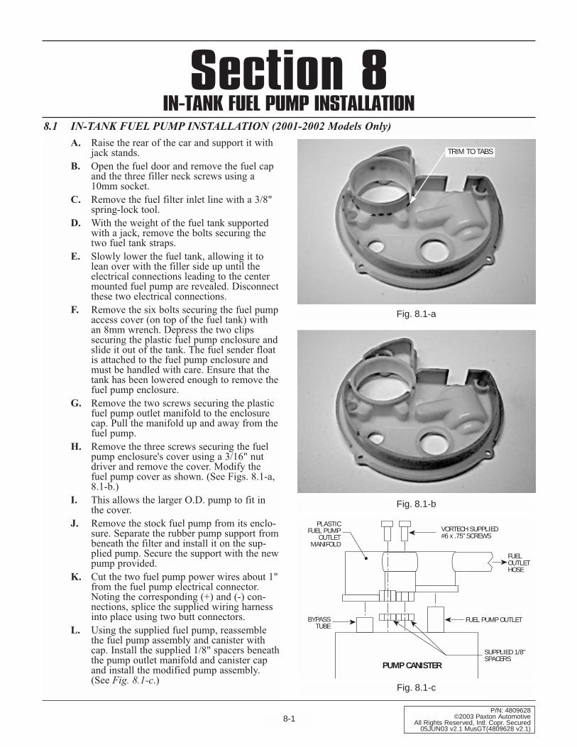
F. Remove the six bolts securing the fuel pumpaccess cover (on top of the fuel tank) withan 8mm wrench. Depress the two clipssecuring the plastic fuel pump enclosure andslide it out of the tank. The fuel sender floatis attached to the fuel pump enclosure andmust be handled with care. Ensure that thetank has been lowered enough to remove thefuel pump enclosure.
G. Remove the two screws securing the plasticfuel pump outlet manifold to the enclosurecap. Pull the manifold up and away from thefuel pump.
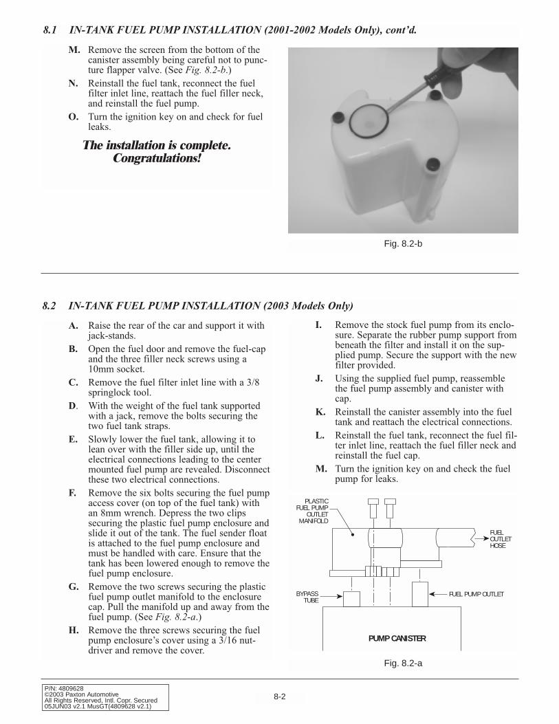
H. Remove the three screws securing the fuelpump enclosure's cover using a 3/16" nutdriver and remove the cover. Modify thefuel pump cover as shown. (See Figs. 8.1-a, 8.1-b.)
I. This allows the larger O.D. pump to fit inthe cover.
J. Remove the stock fuel pump from its enclo-sure. Separate the rubber pump support frombeneath the filter and install it on the sup-plied pump. Secure the support with the newpump provided.
K. Cut the two fuel pump power wires about 1"from the fuel pump electrical connector.Noting the corresponding (+) and (-) con-nections, splice the supplied wiring harnessinto place using two butt connectors.
L. Using the supplied fuel pump, reassemblethe fuel pump assembly and canister withcap. Install the supplied 1/8" spacers beneaththe pump outlet manifold and canister capand install the modified pump assembly.(See Fig. 8.1-c.)
Fig. 8.1-a
Fig. 8.1-b
TRIM TO TABS
BYPASSTUBE
PLASTICFUEL PUMP
OUTLETMANIFOLD
VORTECH SUPPLIED#6 x .75" SCREWS
FUELOUTLETHOSE
FUEL PUMP OUTLET
SUPPLIED 1/8"SPACERS
PUMP CANISTER
Fig. 8.1-c
8-2P/N: 4809628©2003 Paxton AutomotiveAll Rights Reserved, Intl. Copr. Secured05JUN03 v2.1 MusGT(4809628 v2.1)
BYPASSTUBE
PLASTICFUEL PUMP
OUTLETMANIFOLD
FUELOUTLETHOSE
FUEL PUMP OUTLET
PUMP CANISTER
Fig. 8.2-a
M. Remove the screen from the bottom of thecanister assembly being careful not to punc-ture flapper valve. (See Fig. 8.2-b.)
N. Reinstall the fuel tank, reconnect the fuelfilter inlet line, reattach the fuel filler neck,and reinstall the fuel pump.
O. Turn the ignition key on and check for fuelleaks.
The installation is complete.Congratulations!
Fig. 8.2-b
A. Raise the rear of the car and support it withjack-stands.
B. Open the fuel door and remove the fuel-capand the three filler neck screws using a10mm socket.
C. Remove the fuel filter inlet line with a 3/8springlock tool.
D. With the weight of the fuel tank supportedwith a jack, remove the bolts securing thetwo fuel tank straps.
E. Slowly lower the fuel tank, allowing it tolean over with the filler side up, until theelectrical connections leading to the centermounted fuel pump are revealed. Disconnectthese two electrical connections.
F. Remove the six bolts securing the fuel pumpaccess cover (on top of the fuel tank) withan 8mm wrench. Depress the two clipssecuring the plastic fuel pump enclosure andslide it out of the tank. The fuel sender floatis attached to the fuel pump enclosure andmust be handled with care. Ensure that thetank has been lowered enough to remove thefuel pump enclosure.
G. Remove the two screws securing the plasticfuel pump outlet manifold to the enclosurecap. Pull the manifold up and away from thefuel pump. (See Fig. 8.2-a.)
H. Remove the three screws securing the fuelpump enclosure’s cover using a 3/16 nut-driver and remove the cover.
8.1 IN-TANK FUEL PUMP INSTALLATION (2001-2002 Models Only), cont’d.
8.2 IN-TANK FUEL PUMP INSTALLATION (2003 Models Only)
I. Remove the stock fuel pump from its enclo-sure. Separate the rubber pump support frombeneath the filter and install it on the sup-plied pump. Secure the support with the newfilter provided.
J. Using the supplied fuel pump, reassemblethe fuel pump assembly and canister withcap.
K. Reinstall the canister assembly into the fueltank and reattach the electrical connections.
L. Reinstall the fuel tank, reconnect the fuel fil-ter inlet line, reattach the fuel filler neck andreinstall the fuel cap.
M. Turn the ignition key on and check the fuelpump for leaks.
8-3P/N: 4809628
©2003 Paxton AutomotiveAll Rights Reserved, Intl. Copr. Secured
05JUN03 v2.1 MusGT(4809628 v2.1)
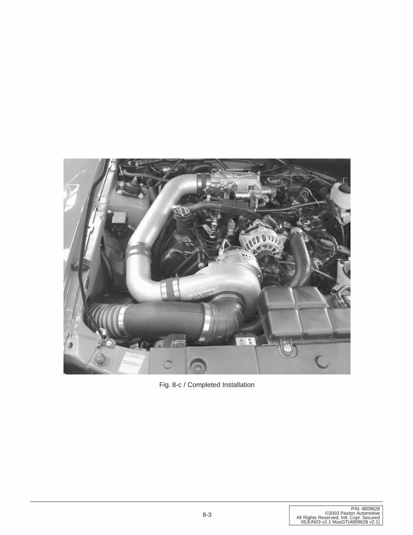
Fig. 8-c / Completed Installation

8-4P/N: 4809628©2003 Paxton AutomotiveAll Rights Reserved, Intl. Copr. Secured05JUN03 v2.1 MusGT(4809628 v2.1)
This Page Left Intentionally Blank.

9-1P/N: 4809628
©2003 Paxton AutomotiveAll Rights Reserved, Intl. Copr. Secured
05JUN03 v2.1 MusGT(4809628 v2.1)
Section 9FINAL ASSEMBLY AND CHECK
We know that you are anxious to get outand drive your new vehicle, but pleasetake a little bit more time to perform
these simple check-out steps.
A Inspect all wiring harnesses and electricalconnections. Make sure that all items areproperly routed, connected and secured. Ifavailable, check grounds with an amp meter.If the ground connection is suspect, connectto the battery ground.
B. Check all hoses, lines, and fittings for prop-erly secured connections..
C. Make certain all fasteners, brackets, andclamps are installed and properly tightened.
D. Check serpentine accessory belt and super-charger drive belts for proper tension andalignment.
E. Cycle ignition key from “off” to the “on”position 4-5 times.
F. Check the entire fuel system for possibleleaks.
G. Start engine and verify that the oil pressureis within normal range.
H. Allow the engine to come up to normaloperating temperature.Turn the engine off.
I. Check the coolant level in the coolant recov-ery bottle and top off as needed.
J. Check the following:• Fluid Leaks• Fluid Levels• Belt Slippage• Throttle Response
Now that the work is done, it’s time to enjoy. PAXTON Automotive wants to thank you forchoosing our product, and wants to remind you thatthe performance and response of your vehicle isnow different that what you are used to. Pleasedrive cautiously until you have grown accustomedto the feel of your vehicle.
Please see the service manual included in your kitfor information on the service and maintenance ofyour PAXTON Supercharger. Belt tightening,troubleshooting, special tuning requirements, andwarranty information is also included in theService Manual.
9.1 FINAL ASSEMBLY AND CHECK

9-2P/N: 4809628©2003 Paxton AutomotiveAll Rights Reserved, Intl. Copr. Secured05JUN03 v2.1 MusGT(4809628 v2.1)
This Page Left Intentionally Blank.

A-1P/N: 4809628
©2003 Paxton AutomotiveAll Rights Reserved, Intl. Copr. Secured
05JUN03 v2.1 MusGT(4809628 v2.1)
APPENDIX
A-2P/N: 4809628©2003 Paxton AutomotiveAll Rights Reserved, Intl. Copr. Secured05JUN03 v2.1 MusGT(4809628 v2.1)
Please realize that PAXTON Automotive is con-stantly improving the performance and look of theNOVI 1000 supercharger. Parts in your kit mayappear differently than what is pictured in this manu-al. This is due to photographs taken in pre-produc-tion, a change in material, costs, or an improvementin performance.
Rest assured that you have purchased the best qualitykit that PAXTON Automotive manufactures at thistime. The installation of the materials will remain thesame.
List of Appendices
Appendix Number.... ..DWG Number............... .DWG Title
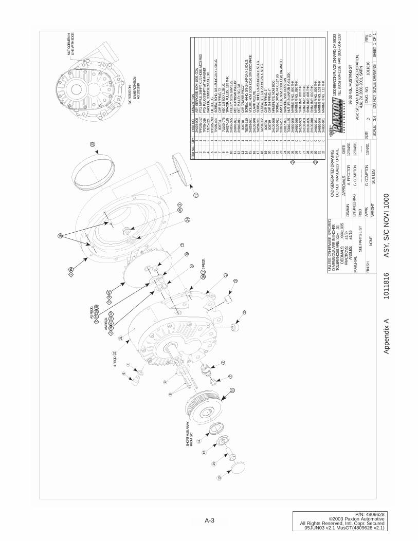
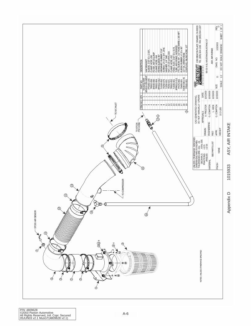
Appendix A 1011816 ASY, S/C NOVI 1000Appendix B 1015309 ASY, RADIATOR HOSE MODIFICATIONAppendix C 1016630 ASY, S/C MOUNTING BRACKETAppendix D 1015933 ASY, AIR INTAKEAppendix E 1017017 ASY, AIR DISCHARGEAppendix F 1019336 ASY, OIL SUPPLYAppendix G 1019328 ASY, OIL RETURNAppendix H 1015506 ASY, COMPRESSOR BYPASSAppendix I 1015530 ASY, FAN RESISTOR RELOC.Appendix J 1017734 ASY, FUEL PUMPAppendix K 7000170 DIAGRAM, BELT ROUTING
A-3P/N: 4809628
©2003 Paxton AutomotiveAll Rights Reserved, Intl. Copr. Secured
05JUN03 v2.1 MusGT(4809628 v2.1)
SCAL
E:
SIZE
DWG.
NO.
D
SHEE
T1
OF1
REV.
DATE
APPR
OVAL
SDR
AWN
ENGI
NEER
ING
R&D
UNLE
SS O
THER
WIS
E S
PECI
FIED
DIM
ENSI
ONS
ARE
IN IN
CHES
TOLE
RANC
ES A
RE:
DECI
MAL
S:.X
X±
.01
.XXX
±.00
5
MAT
ERIA
L
FINI
SHNO
NE
SEE
PART
S LI
ST
DO N
OT S
CALE
DRA
WIN
GW
EIGH
T20
.8 L
BS3:
4
1011
816
B
FRAC
TION
S:AN
GLES
:±1
/16
±1/2
•
ASY,
S/C
NOV
I 100
0 RE
VERS
E RO
TATI
ON,
4.6L
2V,
200
0-20
01, S
ATIN
APPR
.
G. C
OMPT
ON
12/0
4/01
98-0
3 4.
6L M
USTA
NG G
TA.
PRO
CTOR
G. C
OMPT
ON
12/0
4/01
10/4
/01
1300
BEA
CON
PLAC
E O
XNAR
D, C
A 93
033
TEL:
(805
) 604
-133
6 F
AX: (
805)
604
-133
7
CAD
GEN
ERAT
ED D
RAW
ING
,DO
NOT
MAN
UALL
Y U
PDAT
E
----
----
----
---
2 2
1 2 3 4 5 6 7 8 9 10 11 12 13 14 15 16 17 18 19 20 21 22 23 24 25 26 26 27 27 28 29 30 31 32
1 1 2 2 1 1 2 2 1 1 1 1 1 1 1 6 6 2 1 1 1 4 1 1 1 1 0 0 1 0 0 0 0 0
ITEM
NO.
QTY.
PART
NO.
DESC
RIPT
ION
2H22
9-00
07P
P375
-017
7P37
5-01
67J
375-
024
7PP3
75-0
907P
375-
104
0087
047U
100-
075
2H01
7-18
52H
036-
325
2H04
0-02
12H
040-
011
0087
187B
375-
110
2H01
9-02
12H
100-
040
7A25
0-05
17A
250-
052
0087
0600
8719
2H10
0-03
07U
100-
021
2H02
1-20
12H
017-
021
7G01
0-15
52H
060-
030
2H06
0-03
02H
100-
003
2H10
0-00
32H
100-
005
2H10
0-01
02H
060-
031
2H06
0-04
02H
060-
041
ASY,
GEA
RCAS
E, N
OVI 1
000,
CCW
FTG,
NIP
PLE,
3/8
NPT
X 1/
2 HO
SE, M
ODIF
IED
FTG,
PLU
G 3/
8NPT
WIT
H M
AGNE
TW
ASHE
R, C
OPPE
R CR
USH,
3/8
OIL
JET,
LG.
SCRE
W, S
CHD,
3/8
-16U
NC-2
A X
1.00
LG.
CAP,
SHI
PPIN
G, T
2KE
Y, 1
/8 S
Q X
1.25
LG.
SPAC
ER, P
ULLE
Y, .1
85 T
HK.
PULL
EY, S
/C 6
GRV
3.2
5RE
T, C
UP B
LWR
PULL
EYRE
T, P
ULLE
Y, S
/C, 3
/8CA
P, T
AMPE
R PR
OOF
SCRE
W, H
XHD,
3/8
-24U
NF-2
A X
1.00
LG.
VOLU
TE, N
OVI 1
000,
CCW
, STR
DIS
CHAR
GECL
AMP,
VOL
UTE
SCRE
W, H
XHD,
1/4
-20U
NC-2
A X
.50
LG.
SCRE
W, S
ET, 1
/4-2
0UNC
-2A
X .5
0 LG
.CA
P, S
HIPP
ING,
3"
CAP,
SHI
PPIN
G, 4
"NA
MEP
LATE
, NOV
I 100
0SC
REW
, DRI
VE, #
4 X
.187
LG.
IMPE
LLER
, NOV
I 100
0, C
CW, B
ALAN
CED
WAS
HER,
ANT
I-ROT
ATIO
NNU
T, 3
/8-2
4UNF
-2B,
FLG
LOC
KM
ATIN
G RI
NG, .
090
THK
MAT
ING
RING
, .09
0 TH
KSH
IM, I
MP,
.003
THK
.SH
IM, I
MP,
.003
THK
.SH
IM, I
MP,
.005
THK
.SH
IM, I
MP,
.010
THK
.M
ATIN
G RI
NG, .
099
THK
MAT
ING
RING
, .10
3 TH
KM
ATIN
G RI
NG, .
112
THK
20
18
152
24
325
19
7
4
6 RE
QD.
1617
3
3
17
2
11
12
14
13
SHOR
T HU
B AW
AYFR
OM S
/C
10
8
9
64
224
REQD
AS R
EQD.
3231
3026
2
AS R
EQD. 29
2827
2
423
2
21
5
NUT
CORN
ER IN
LINE
WIT
H ED
GE
SAM
E RO
TATI
ONAS
101
1810
S/C
ROTA
TION
App
endi
x A
10
1181
6A
SY,
S/C
NO
VI
1000
A-4P/N: 4809628©2003 Paxton AutomotiveAll Rights Reserved, Intl. Copr. Secured05JUN03 v2.1 MusGT(4809628 v2.1)
ITEM
NO.
QTY.
PART
NO.
DESC
RIPT
ION
23
7R00
2-02
4CL
AMP,
HOS
E #2
43
14P
FH01
4-01
1RE
DUCE
R, R
ADIA
TOR
HOSE
41
4PFH
014-
020-
1
SCAL
E:
SIZE
DWG.
NO.
D
SHEE
T1
OF1
REV.
DATE
APPR
OVAL
SDR
AWN
ENGI
NEER
ING
R&D
UNLE
SS O
THER
WIS
E S
PECI
FIED
DIM
ENSI
ONS
ARE
IN IN
CHES
TOLE
RANC
ES A
RE:
DECI
MAL
S:.X
X±
.01
.XXX
±.00
5
MAT
ERIA
L
FINI
SHNO
NE
SEE
PART
S LI
ST
DO N
OT S
CALE
DRA
WIN
GW
EIGH
T?.
? LB
S1:
1.25
1015
309
A
FRAC
TION
S:AN
GLES
:±1
/16
±1/2
•
ASY,
RAD
IATO
R HO
SE M
ODIF
ICAT
ION
APPR
.
9/18
/00
99-0
3 4.
6L M
USTA
NG G
TAP
1300
BEA
CON
PLAC
E O
XNAR
D, C
A 93
033
TEL:
(805
) 604
-133
6 F
AX: (
805)
604
-133
7
CAD
GEN
ERAT
ED D
RAW
ING
,DO
NOT
MAN
UALL
Y U
PDAT
E
TO M
ODIF
IED
STOC
K RA
DIAT
OR H
OSE
2
TO R
ADIA
TOR
MOD
IFIE
D4
2
3
2
CUT
HERE
(1" F
ROM
END
)
1.50
" INT
ERNA
L DI
AMET
ER
1
1.25
" INT
ERNA
L DI
AMET
ER
CUT
HERE
App
endi
x B
1015
309
AS
Y, R
AD
IATO
R H
OS
E M
OD
IFIC
ATIO
N

A-5P/N: 4809628
©2003 Paxton AutomotiveAll Rights Reserved, Intl. Copr. Secured
05JUN03 v2.1 MusGT(4809628 v2.1)
SCAL
E:
SIZE
DWG.
NO.
D
SHEE
T1
OF1
REV.
DATE
APPR
OVAL
SDR
AWN
ENGI
NEER
ING
R&D
UNLE
SS O
THER
WIS
E S
PECI
FIED
DIM
ENSI
ONS
ARE
IN IN
CHES
TOLE
RANC
ES A
RE:
DECI
MAL
S:.X
X±
.01
.XXX
±.00
5
MAT
ERIA
L
FINI
SHNO
NE
SEE
PART
S LI
ST
DO N
OT S
CALE
DRA
WIN
GW
EIGH
T7.
3 LB
S1:
1.5
1016
630
B
FRAC
TION
S:AN
GLES
:±1
/16
±1/2
•
ASY,
S/C
NOV
I 100
0 FO
WAR
D RO
TATI
ONPR
OWLE
R, P
OLIS
HED
WIT
H UP
GRAD
EAP
PR.
G. C
OMPT
ON
10/2
5/00
99-0
3 4.
6L M
USTA
NG G
TA.
PRO
CTOR
G. C
OMPT
ON
11/6
/00
12/1
1/00
1300
BEA
CON
PLAC
E O
XNAR
D, C
A 93
033
TEL:
(805
) 604
-133
6 F
AX: (
805)
604
-133
7
CAD
GEN
ERAT
ED D
RAW
ING
,DO
NOT
MAN
UALL
Y U
PDAT
E
L. K
ECK
12/1
1/00
122
23
REPL
ACE
STOC
K FL
ANGE
-HEA
D
227
14
13
2221
2622
12
29
1026
2215
20
TO E
NGIN
E
TO S
TOCK
8
9
16
5
5
TO E
NGIN
E2
19
1
7
TO S
/C3
2
6
TO S
/C2
3
2524
1
5
TO E
NGIN
E18
17
TO E
NGIN
E28
22
42
TO S
TOCK
REPL
ACE
STOC
K ST
UDON
TIM
ING
COVE
R
2211
NOTE
S: U
NLES
S OT
HERW
ISE
SPEC
IFIE
D:
ITEM
NO.
QTY.
PART
NO.
DESC
RIPT
ION
1 2 3 4 5 6 7 8 9 10 11 12 13 14 15 16 17 18 19 20 21 22 23 24 25 26 27 28 29 30
1 10 6 2 3 1 1 1 1 1 1 1 1 1 1 1 1 1 1 1 1 6 1 1 1 2 1 1 1 1
4PFL
010-
034
7J37
5-04
47A
375-
124
7A37
5-27
62A
017-
875-
022A
017-
876-
024P
FL01
7-01
14P
FL01
0-02
12A
017-
750-
034P
FL01
0-04
47C
080-
030
4PFH
017-
021
1210
517
2H04
0-01
14P
FL01
7-02
12A
017-
875-
067J
006-
093
7C06
0-08
07A
375-
475
7PC0
80-3
357C
080-
066
7K31
2-00
17C
080-
051
7J01
0-00
27C
010-
060
7C08
0-05
67A
375-
178
7C08
0-16
07C
080-
023
2A04
6-07
3
PLAT
E, F
RONT
, S/C
MTG
BRK
TW
ASHE
R, F
LAT,
3/8
SCRE
W, H
XHD,
3/8
-16U
NC-2
A x
1.25
LG.
SCRE
W, H
XHD,
3/8
-16U
NC-2
A x
2.75
LG.
SPAC
ER, .
875
x .4
04 x
1.5
65 L
G.SP
ACER
, .87
5 x
.328
x 1
.500
SPAC
ER, F
LARE
D, 3
/8PL
ATE,
IDLE
R M
TGSP
ACER
, .75
0 x
.328
x .1
30 L
G.PL
ATE,
REA
R, S
/C M
TG B
RKT
SCRE
W, H
XHD,
M8
x 1.
25 x
30m
mCO
LLAR
, IDL
ERPU
LLEY
, IDL
ERRE
T, P
ULLE
Y, 3
/8SP
ACER
, .87
5 HE
X x
1.27
5 LG
.SP
ACER
, .87
5 x
.404
x 1
.235
LG.
WAS
HER,
FLA
T, 6
mm
SCRE
W, S
CHD,
M6
x 1.
00 x
80m
mSC
REW
, HXH
D, 3
/8-1
6UNC
-2A
x 4.
75 L
G.ST
UD, M
8 x
1.25
X 3
.35"
LG.
SCRE
W, H
XHD,
M8
x 1.
25 x
65m
mW
ASHE
R, F
LAT,
5/1
6SC
REW
, HXH
D, M
8 x
1.25
x 5
0mm
WAS
HER,
FLA
T, 1
0mm
SCRE
W, H
XHD,
M10
x 1
.50
x 60
mm
SCRE
W, H
XHD,
M8
x 1.
25 x
55m
mSC
REW
, HXH
D, 3
/8-1
6UNC
-2A
x 1.
75 L
G.SC
REW
, HXH
D, M
8 x
1.25
x 1
60m
mSC
REW
, FHS
H, M
8 x
1.25
x 2
0mm
BELT
, 6 G
RVA
11111
App
endi
x C
1016
630
AS
Y, S
/C M
OU
NT
ING
BR
AC
KE
T
A-6P/N: 4809628©2003 Paxton AutomotiveAll Rights Reserved, Intl. Copr. Secured05JUN03 v2.1 MusGT(4809628 v2.1)
SCAL
E:
SIZE
DWG.
NO.
D
SHEE
T1
OF1
REV.
DATE
APPR
OVAL
SDR
AWN
ENGI
NEER
ING
R&D
UNLE
SS O
THER
WIS
E S
PECI
FIED
DIM
ENSI
ONS
ARE
IN IN
CHES
TOLE
RANC
ES A
RE:
DECI
MAL
S:.X
X±
.01
.XXX
±.00
5
MAT
ERIA
L
FINI
SHNO
NE
SEE
PART
S LI
ST
DO N
OT S
CALE
DRA
WIN
GW
EIGH
T10
.3 L
BS1:
2
1015
933
D
FRAC
TION
S:AN
GLES
:±1
/16
±1/2
•
ASY,
AIR
INTA
KE
APPR
.
G. C
OMPT
ON
10/2
3/00
99-0
3 4.
6L M
USTA
NG/M
USTA
NG G
TA.
PRO
CTOR
G. C
OMPT
ON
10/3
0/00
10/3
0/00
1300
BEA
CON
PLAC
E O
XNAR
D, C
A 93
033
TEL:
(805
) 604
-133
6 F
AX: (
805)
604
-133
7
CAD
GEN
ERAT
ED D
RAW
ING
,DO
NOT
MAN
UALL
Y U
PDAT
E
L. K
ECK
10/3
0/00
NOTE
S: U
NLES
S OT
HERW
ISE
SPEC
IFIE
D
49
10 48
4
1
6 3
11
7ST
OCK
AIR
SENS
OR
12
11
13
TO C
OMPR
ESSO
R
14
1615
TO S
TOCK
PVC
HOSE
117
5
2 3
TO S
/C IN
LET
1
ITEM
NO.
QTY.
PART
NO.
DESC
RIPT
ION
1 2 4 5 6 7 8 9 11 12 13 14 15 16 17 18 1931 1 2 1 3 1 1 4 4 4 2 1 1 1 1 1 11
4FH0
10-0
50-B
ENT
7PS3
50-2
007R
002-
056
8H04
0-09
07R
002-
064
4FH0
12-0
127U
100-
052
7A25
0-07
57J
250-
001
7F25
0-02
17R
002-
052
7U03
5-00
14P
FK01
2-01
17P
375-
055
7S40
0-00
17U
030-
036
x 45
7P50
0-00
1
Mus
tang
MAF
SLEE
VE, 3
.50"
ID x
2.0
0"L
CLAM
P, H
OSE,
#56
FILT
ER, A
IR w
/CLA
MP
CLAM
P, H
OSE,
#64
INTA
KE E
LBOW
, 90°
GROM
MET
, RUB
BER
7/16
"SC
REW
, 1/4
-20
x 3/
4", Z
INC
WAS
HER,
1/4
" SAE
NUT,
1/4
-20
w/N
YLOC
KCL
AMP,
HOS
E, #
52HO
SE, F
LEX,
3.5
0" ID
x 9
.0"L
TUBE
, AIR
INTA
KE, M
ODIF
IED
FTG,
ELB
OW, 9
0°, 1
/2" H
OSE
BARB
x 3
/8 N
PTEL
BOW
, RUB
BER,
4" I
D x
90°
COUP
LING
, INL
INE
HOSE
, 1/2
"1/
2" O
IL D
RAIN
HOS
E
MAF
BRA
CKET
App
endi
x D
1015
933
AS
Y, A
IR I
NTA
KE
A-7P/N: 4809628
©2003 Paxton AutomotiveAll Rights Reserved, Intl. Copr. Secured
05JUN03 v2.1 MusGT(4809628 v2.1)
L. K
ECK
10/3
0/00
SCAL
E:
SIZE
DWG.
NO.
D
SHEE
T1
OF1
REV.
DATE
APPR
OVAL
SDR
AWN
ENGI
NEER
ING
R&D
UNLE
SS O
THER
WIS
E S
PECI
FIED
DIM
ENSI
ONS
ARE
IN IN
CHES
TOLE
RANC
ES A
RE:
DECI
MAL
S:.X
X±
.01
.XXX
±.00
5
MAT
ERIA
L
FINI
SHNO
NE
SEE
PART
S LI
ST
DO N
OT S
CALE
DRA
WIN
GW
EIGH
T3.
6 LB
S1:
1.75
1017
017
A
FRAC
TION
S:AN
GLES
:±1
/16
±1/2
•
ASY,
AIR
DIS
CHAR
GE
APPR
.
G. C
OMPT
ON
10/2
0/00
99-0
3 4.
6L M
USTA
NG G
TA.
PRO
CTOR
G. C
OMPT
ON
10/2
3/00
10/3
0/00
1300
BEA
CON
PLAC
E O
XNAR
D, C
A 93
033
TEL:
(805
) 604
-133
6 F
AX: (
805)
604
-133
7
CAD
GEN
ERAT
ED D
RAW
ING
,DO
NOT
MAN
UALL
Y U
PDAT
E
23
46
52
71
81
91
1017
017-
P
1017
018
SLV,
BLK
, 3.0
0D x
2.0
0HO
SE C
LAM
P,CL
AMP,
HOS
E #1
0
ITEM
NO.
QTY.
PART
NO.
DESC
RIPT
ION
7PS3
00-2
007R
002-
048
7R00
2-01
04P
FH01
2-02
04P
FH01
2-04
17U
038-
000-
9
1 3 1 1
1 1 1TE
ST1
4PFH
012-
020
4PFH
012-
048
4PFH
012-
028
ASY
ITEM
QTPA
RT
NIPP
LE O
N P/
N 48
1012
7-6
32
64
TO S
/C O
UTLE
T
7
5
9
TO A
NTI-R
EVER
SION
5
TO T
HROT
TLE
BODY
8
App
endi
x E
1017
017
AS
Y, A
IR D
ISC
HA
RG
E

A-8P/N: 4809628©2003 Paxton AutomotiveAll Rights Reserved, Intl. Copr. Secured05JUN03 v2.1 MusGT(4809628 v2.1)
1300
BEA
CON
PLAC
E O
XNAR
D, C
A 93
033
TEL:
(805
) 604
-133
6 F
AX: (
805)
604
-133
7
CAD
GEN
ERAT
ED D
RAW
ING
,DO
NOT
MAN
UALL
Y U
PDAT
E
SCAL
E:
SIZE
DWG.
NO.
C
SHEE
T1
OF1
REV.
DATE
APPR
OVAL
SDR
AWN
ENGI
NEER
ING
R&D
UNLE
SS O
THER
WIS
E S
PECI
FIED
DIM
ENSI
ONS
ARE
IN IN
CHES
TOLE
RANC
ES A
RE:
DECI
MAL
S:.X
X±
.01
.XXX
±.00
5
MAT
ERIA
L
FINI
SHNO
NE
SEE
PART
S LI
ST
DO N
OT S
CALE
DRA
WIN
GW
EIGH
T.2
LBS
3:4
1019
336
B
FRAC
TION
S:AN
GLES
:±1
/16
±1/2
•
ASY,
S/C
OIL
SUP
PLY
APPR
.
6/14
/99
99-0
3 4.
6L M
USTA
NG G
TJF
C
1
1 2 3 4
1 1 1 1
HOSE
, OIL
SS
BRAI
D, A
N4 x
AN4
, 46.
5" L
G.IT
EM N
O.QT
Y.PA
RT N
O.DE
SCRI
PTIO
N
7U25
0-00
0-46
5
7P25
0-03
4
7P12
5-00
4
7P25
0-08
2
FTG,
STR
EET
TEE,
1/4
NPT
FTG,
90°
ELB
OW, A
N4 x
1/8
NPT
FTG,
90°
ELB
OW, A
N4 x
1/4
NPT
OIL
FEED
HOS
E, 4
6.5"
-4 S
TRT
3
TO S
/C A
SY
STOC
K OI
L SE
NDER
LOC
ATIO
N
2
4
App
endi
x F
1019
336
AS
Y, O
IL S
UP
PLY

A-9P/N: 4809628
©2003 Paxton AutomotiveAll Rights Reserved, Intl. Copr. Secured
05JUN03 v2.1 MusGT(4809628 v2.1)
SCAL
E:
SIZE
DWG.
NO.
C
SHEE
T1
OF1
REV.
DATE
APPR
OVAL
SDR
AWN
ENGI
NEER
ING
R&D
UNLE
SS O
THER
WIS
E S
PECI
FIED
DIM
ENSI
ONS
ARE
IN IN
CHES
TOLE
RANC
ES A
RE:
DECI
MAL
S:.X
X±
.01
.XXX
±.00
5
MAT
ERIA
L
FINI
SHNO
NE
SEE
PART
S LI
ST
DO N
OT S
CALE
DRA
WIN
GW
EIGH
T.8
LBS
3:4
1019
328
C
FRAC
TION
S:AN
GLES
:±1
/16
±1/2
•
ASY,
OIL
RET
URN
APPR
.
4/5/
0099
-03
4.6L
MUS
TANG
JFC
1300
BEA
CON
PLAC
E O
XNAR
D, C
A 93
033
TEL:
(805
) 604
-133
6 F
AX: (
805)
604
-133
7
CAD
GEN
ERAT
ED D
RAW
ING
,DO
NOT
MAN
UALL
Y U
PDAT
E
LOCA
TION
FOR
ITEM
5(F
RONT
OF
OIL
PAN)
1
2 3 4 5 6 7
1 1 1 2 1 1
7P50
0-06
37P
500-
052
7P37
5-05
37R
002-
010
7T64
0-01
17U
030-
036x
13
FTG,
HOS
E EN
D, A
N8 X
1/2
BAR
BFT
G, 9
0^ S
WIV
EL, A
N8 M
ALE
X AN
8 FE
MFT
G, S
TR, A
N8 X
3/8
NPT
CLAM
P, H
OSE,
#10
PUNC
H, O
IL P
AN
ITEM
NO.
QTY.
PART
NO.
DESC
RIPT
ION
2
5
5
7
TO S
/C A
SY
3
4
TO O
IL P
AN
PUNC
H HO
LEW
ITH
ITEM
6OIL
PAN
1.00
1.75
NOTE
S: U
NLES
S OT
HERW
ISE
SPEC
IFIE
D
1. S
HIP
THIS
ITEM
LOO
SE.
App
endi
x G
1019
328
AS
Y, O
IL R
ET
UR
N
A-10P/N: 4809628©2003 Paxton AutomotiveAll Rights Reserved, Intl. Copr. Secured05JUN03 v2.1 MusGT(4809628 v2.1)
SCAL
E:
SIZE
DWG.
NO.
D
SHEE
T1
OF1
REV.
DATE
APPR
OVAL
SDR
AWN
ENGI
NEER
ING
R&D
UNLE
SS O
THER
WIS
E S
PECI
FIED
DIM
ENSI
ONS
ARE
IN IN
CHES
TOLE
RANC
ES A
RE:
DECI
MAL
S:.X
X±
.01
.XXX
±.00
5
MAT
ERIA
L
FINI
SHNO
NE
SEE
PART
S LI
ST
DO N
OT S
CALE
DRA
WIN
GW
EIGH
T2.
8 LB
S3:
4
1015
506
D
FRAC
TION
S:AN
GLES
:±1
/16
±1/2
•
ASY,
COM
PRES
SOR
BY-P
ASS
APPR
.
8/22
/99
99-0
3 4.
6L M
USTA
NGJF
C
1300
BEA
CON
PLAC
E O
XNAR
D, C
A 93
033
TEL:
(805
) 604
-133
6 F
AX: (
805)
604
-133
7
CAD
GEN
ERAT
ED D
RAW
ING
,DO
NOT
MAN
UALL
Y U
PDAT
E
-01
5
4
TO A
IR IN
TAKE
ASY
4
1
10
6
TO E
XIST
ING
VACU
UM L
INE
TO A
IR D
ISCH
ARGE
ASY
4
-02
5 4
D
ITEM
NO.
QTY.
PART
NO.
DESC
RIPT
ION
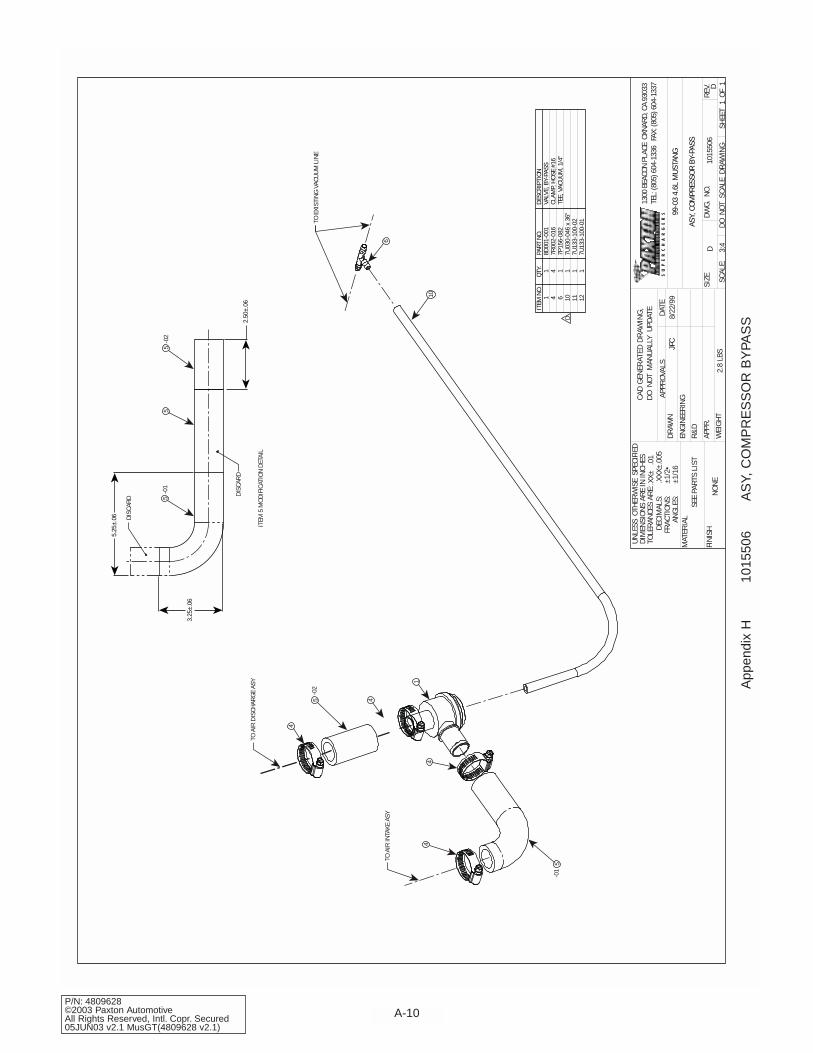
1 4 6 10 11 12
1 4 1 1 1 1
8D00
1-00
17R
002-
016
7P15
6-08
27U
030-
046
x 36
"7U
133-
100-
027U
133-
100-
01
VALV
E, B
Y-PA
SSCL
AMP,
HOS
E #1
6TE
E, V
ACUU
M, 1
/4"
2.50
±.06
3.25
±.06
5.25
±.06 DI
SCAR
D
-01
5-0
25
5
ITEM
5 M
ODIF
ICAT
ION
DETA
IL
DISC
ARD
App
endi
x H
1015
506
AS
Y, C
OM
PR
ES
SO
R B
YPA
SS

A-11P/N: 4809628
©2003 Paxton AutomotiveAll Rights Reserved, Intl. Copr. Secured
05JUN03 v2.1 MusGT(4809628 v2.1)
ITEM
NO.
QTY.
PART
NO.
DESC
RIPT
ION
1 2 3 4 5
1 2 4 2 2
4PFL
010-
041
7E01
4-07
5
7J01
0-00
1
7F01
0-02
4
7C01
0-07
5
BRKT
, FAN
RES
ISTO
R RE
LOCA
TION
SCRE
W, #
14 X
.75
LG, S
ELF
TAPP
ING
WAS
HER,
FLA
T, #
10
NUT,
HEX
, 10-
24UN
C-2B
, STE
EL W
ITH
NYLO
K
SCRE
W, S
HCS,
10-
24UN
C-2A
X .7
5 LG
, STE
EL G
R5
L. K
ECK
12/1
1/00
SCAL
E:
SIZE
DWG.
NO.
C
SHEE
T1
OF1
REV.
DATE
APPR
OVAL
SDR
AWN
ENGI
NEER
ING
R&D
UNLE
SS O
THER
WIS
E S
PECI
FIED
DIM
ENSI
ONS
ARE
IN IN
CHES
TOLE
RANC
ES A
RE:
DECI
MAL
S:.X
X±
.01
.XXX
±.00
5
MAT
ERIA
L
FINI
SHNO
NE
SEE
PART
S LI
ST
DO N
OT S
CALE
DRA
WIN
GW
EIGH
T.2
LBS
2:1
1015
530
A
FRAC
TION
S:AN
GLES
:±1
/16
±1/2
•
ASY,
FAN
RES
ISTO
R RE
LOCA
TION
APPR
.
G. C
OMPT
ON
11/7
/00
2001
4.6
L M
USTA
NG G
TG.
COM
PTON
G. C
OMPT
ON
11/7
/00
12/1
1/00
1300
BEA
CON
PLAC
E O
XNAR
D, C
A 93
033
TEL:
(805
) 604
-133
6 F
AX: (
805)
604
-133
7
CAD
GEN
ERAT
ED D
RAW
ING
,DO
NOT
MAN
UALL
Y U
PDAT
E
2 RE
QD2
2 RE
QD3
5
1
2 RE
QD4
3
App
endi
x I
1015
530
AS
Y, F
AN
RE
SIS
TOR
RE
LOC
.

A-12P/N: 4809628©2003 Paxton AutomotiveAll Rights Reserved, Intl. Copr. Secured05JUN03 v2.1 MusGT(4809628 v2.1)
ITEM
NO.
QTY.
PART
NO.
DESC
RIPT
ION
PIGT
AIL
CONN
CTR,
FUE
L PU
MP
SPAC
ER, .
312
OD/.1
4 ID
14-1
6AW
G SO
LDER
LESS
CON
NECT
OR
SCRE
W, S
HTM
TL, H
XHD,
#6
x .7
5 LG
.
2 3 4 5
1 2 2 2
5W00
1-05
2
2A01
7-04
8
5W00
1-01
3
7E00
6-07
5
SCAL
E:
SIZE
DWG.
NO.
B
SHEE
T1
OF1
REV.
DATE
APPR
OVAL
SDR
AWN
ENGI
NEER
ING
R&D
UNLE
SS O
THER
WIS
E S
PECI
FIED
DIM
ENSI
ONS
ARE
IN IN
CHES
TOLE
RANC
ES A
RE:
DECI
MAL
S:.X
X±
.01
.XXX
±.00
5
MAT
ERIA
L
FINI
SHNO
NE
SEE
PART
S LI
ST
DO N
OT S
CALE
DRA
WIN
GW
EIGH
T2
LBS
1:1
1017
734
NC
FRAC
TION
S:AN
GLES
:±1
/16
±1/2
•
ASY,
FUE
L PU
MP
APPR
.
5/3/
0199
-02
4.6L
MUS
TANG
GT
G. C
OMPT
ON
NOTE
S: U
NLES
S OT
HERW
ISE
SPEC
IFIE
D
1. A
LL IT
EMS
SHIP
PED
LOOS
E.13
00 B
EACO
N PL
ACE
OXN
ARD,
CA
9303
3TE
L: (8
05) 6
04-1
336
FAX
: (80
5) 6
04-1
337
CAD
GEN
ERAT
ED D
RAW
ING
,DO
NOT
MAN
UALL
Y U
PDAT
E
App
endi
x J
1017
734
AS
Y, F
UE
L P
UM
P
A-13P/N: 4809628
©2003 Paxton AutomotiveAll Rights Reserved, Intl. Copr. Secured
05JUN03 v2.1 MusGT(4809628 v2.1)
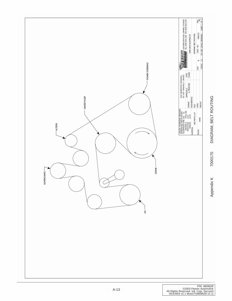
WAT
ER P
UMP
POW
ER S
TEER
ING
ALTE
RN
SUPE
RCHA
RG
A/C
CRAN
K
1300
BEA
CON
PLAC
E O
XNAR
D, C
A 93
033
TEL:
(805
) 604
-133
6 F
AX: (
805)
604
-133
7
CAD
GEN
ERAT
ED D
RAW
ING
,DO
NOT
MAN
UALL
Y U
PDAT
E
SCAL
E:
SIZE
DWG.
NO.
B
SHEE
T1
OF1
REV.
DATE
APPR
OVAL
SDR
AWN
ENGI
NEER
ING
R&D
UNLE
SS O
THER
WIS
E S
PECI
FIED
DIM
ENSI
ONS
ARE
IN IN
CHES
TOLE
RANC
ES A
RE:
DECI
MAL
S:.X
X±
.01
.XXX
±.00
5
MAT
ERIA
L
FINI
SHNO
NE
SEE
PART
S LI
ST
DO N
OT S
CALE
DRA
WIN
GW
EIGH
T1:
1
7000
170
NC
FRAC
TION
S:AN
GLES
:±1
/16
±1/2
•
DIAG
RAM
, BEL
T RO
UTIN
G
APPR
.
7/10
/00
1999
-200
3 M
USTA
NG G
TA.
PRO
CTOR
App
endi
x K
7000
170
DIA
GR
AM
, B
ELT
RO
UT
ING

P/N: 4809628©2003 Paxton AutomotiveAll Rights Reserved, Intl. Copr. Secured05JUN03 v2.1 MusGT(4809628 v2.1)
Paxton Automotive . 1300 Beacon Place . Oxnard CA 93033805 604-1336 . FAX (805) 604-1337