pb slide template - california department of transportation pdf/lesson 7 rev 6-6-09.pdf · 7-3...
TRANSCRIPT

7-1
CIRCULAR FAILURE
Lesson 7

7-2
LESSON 7 – ANALYSIS of CIRCULAR FAILURE
Learning Outcomes -
Analyze structural geologic and slope
geometric conditions using stereonets;
Analyze for Circular Failure using Design
Charts;
Determine critical tension crack location and
depth.
7-3
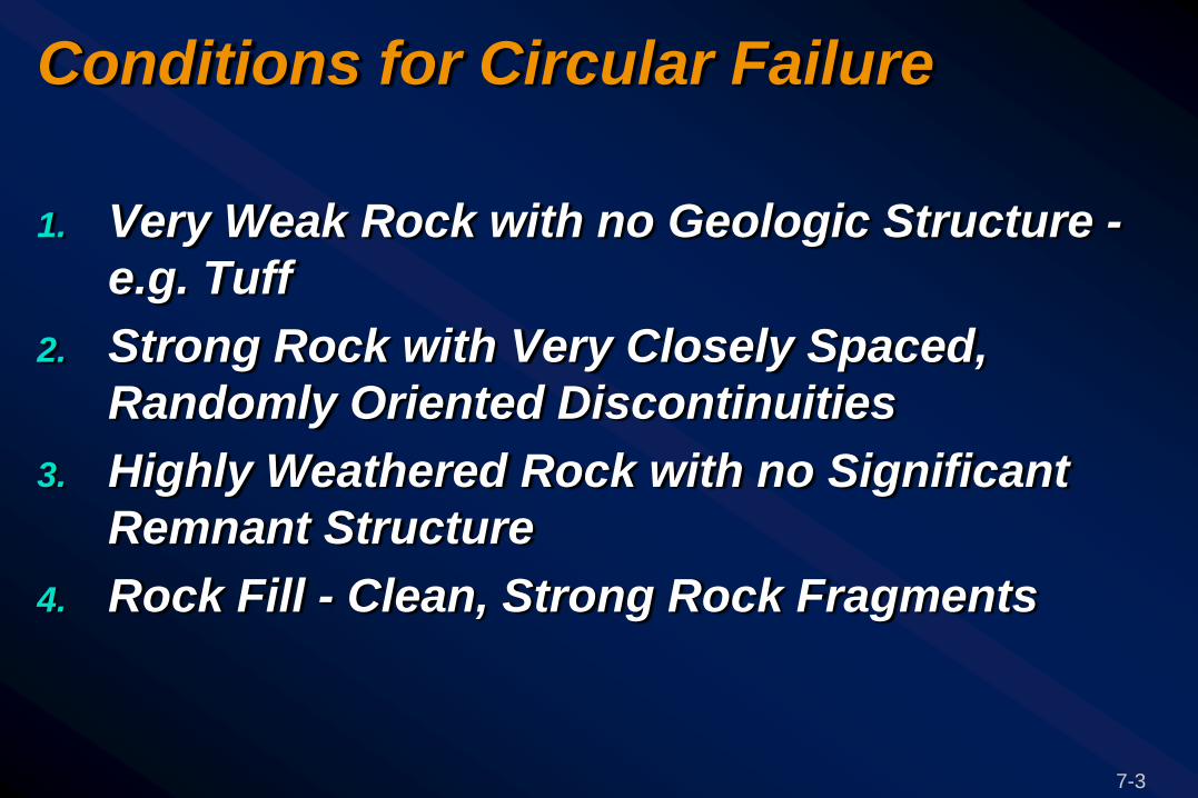
Conditions for Circular Failure
1. Very Weak Rock with no Geologic Structure -
e.g. Tuff
2. Strong Rock with Very Closely Spaced,
Randomly Oriented Discontinuities
3. Highly Weathered Rock with no Significant
Remnant Structure
4. Rock Fill - Clean, Strong Rock Fragments

7-4
Stereoplot of Circular Failure

7-5
1. Very weak rock
with no structure

2. Strong rock with
closely spaced fractures

7-7
2. Strong rock with closely
spaced fractures

7-8
3. Highly weathered rock
with little remnant
structure

3. Highly weathered rock
with little remnant
structure

7-10
3. Highly weathered rock
with little remnant
structure

7-11
4. Rock Fill –
waste dumps
embankments
7-12
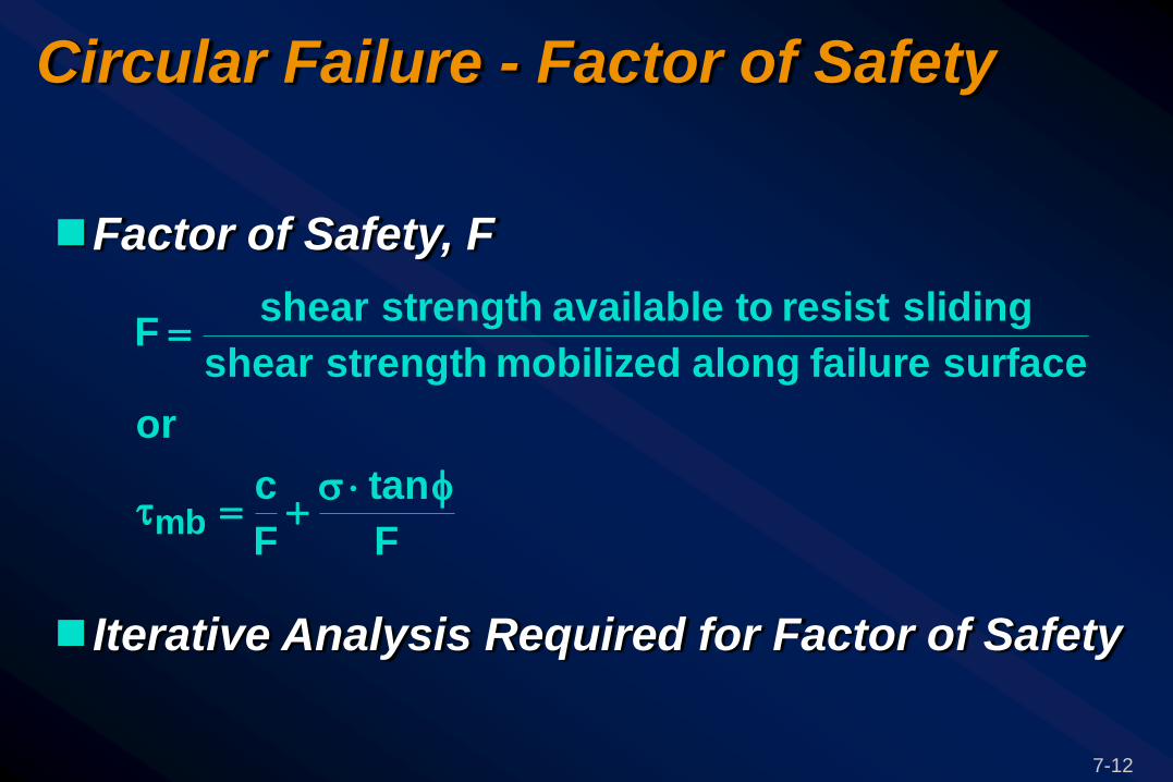
Circular Failure - Factor of Safety
Factor of Safety, F
Iterative Analysis Required for Factor of Safety
F
tan
F
c
or
surfacefailurealongmobilizedstrengthshear
slidingresisttoavailablestrengthshearF
mb

7-13
Circular Failure Design Charts - Assumptions
Material Homogeneous with Uniform Shear Strength on Rupture Surface
Shear Strength () Defined by Cohesion (c) and Friction Angle (), = c + tan
Circular Rupture Surface, through Toe
Vertical Tension Crack
Rupture Surface for Minimum FOS
Ground Water - no Perched Water Tables
Material Density at 18.9 kN/cu. m.

7-14
Ground Water Flow Assumptions
Water table intersects ground surface distance (x.H) behind crest

7-15
Ground Water Flow Assumptions

7-16
Method of Analysis
Sequence of steps to find Factor of Safety

7-17
“Forward” Analysis
To determine Factor of
Safety, F:
Known Values:
Strength parameters, Φ, c
Slope height, H
Slope angle, Ψf
Material density, γ
3
2
1
7-18
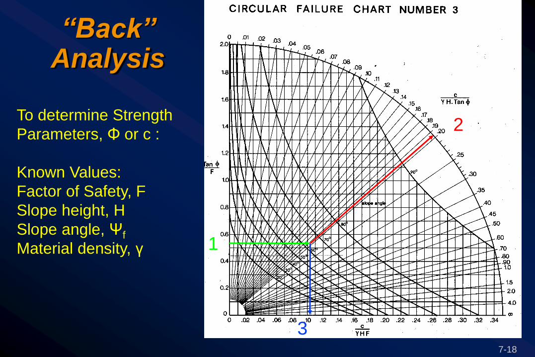
“Back” Analysis
To determine Strength
Parameters, Φ or c :
Known Values:
Factor of Safety, F
Slope height, H
Slope angle, Ψf
Material density, γ
3
1
2

7-19
Circular Failure - Location of Critical Failure Surface
Center of Circle defined by X,Y co-ordinates, Tension Crack by Distance b
Figure 7-4 Drained
Figure 7-5 With ground water

7-20
Circular Failure - Features of Two Dimensional XSTABL Analysis
Slope Shape Defined
Non-homogeneous materials
Multiple Ground Water Tables
Mohr-Coulomb or Hoek-Brown Strengths
External Loads, e.g. Bridge Abutments
Earthquake forces (pseudo-static)
Failure Surface Shape Defined
Deterministic Analysis

7-21
Circular Failure - Two Dimensional Stability Analysis

I-90 Snoqualmie Pass East
Hyak to Keechelus Dam
Pro
ject
No
. 0
62-2
002
Date
: S
epte
mber,
2008
Figure 3
Median Wall Stability Analysis: Circular Failure with Embankment Soil
Case FS Embankment Only, Transient WT - static: 2.67
Embankment & Dowels, Transient – static: 2.77
Embankment Only, Transient – 0.175g: 1.69
Embankment & Dowels, Transient – 0.175g: 1.78
Example Circular Failure - Two Dimensional Stability Analysis

7-23
Circular Failure - Three Dimensional Stability Analysis

7-24
LESSON 7 – ANALYSIS of CIRCULAR FAILURE
Learning Outcomes -
Analyze structural geologic and slope geometric
conditions using stereonets;
Analyze for Circular Failure using Design Charts;
Determine critical tension crack location and
depth.