pbl 1
TRANSCRIPT

GMIGERMAN-MALAYSIAN INSTITUTE
Group member : Syed Ahmad Destar bin Syed Mohd AzizSheratul Ashikin bt. Zamarudin Nazirul Hakim bin A. ManapNorallif bin Norijan
AC ASYNCHRONOUS MOTOR
TTO : Sir Muhairi
OVERVIEW
WHAT IS AC ASYNCHRONOUS MOTOR?
TYPE OF AC ASYNCHRONOUS MOTOR
WORKING PRINCIPLE
BASIC CONSTRUCTION AND CHARACTERISTICS
APPLICATION OF ASYNCHRONOUS MOTOR

WHAT IS AC ASYNCHRONOUS MOTOR?

The induction motor is a common form of asynchronous motor
Power is supplied to the rotor by means of electromagnetic induction
The speed and the torque control in various types of AC induction motors
The simplest and most rugged electric motor and consists of two basic electrical assemblies:• the stator• the rotor

TYPE OF ASYNCHROUNOUS MOTOR
Asynchronous motor
3-phase
Squirrel cage Double poles
2 separate winding
Dahl ender
Slip-ring
Single phase
Resistor start
Capacitor start
Capacitor start-run
Permanent capacitor
Commutator
Universal
Repulsion

DEMONSTRATION OF INDUCTION MOTOR

PRINCIPLE OF 3 PHASE INDUCTION MOTOR
The current – carrying conductors kept in a magnetic field will tend to create a force.
The rotor of the induction motor is not electrically connected to the stator, but induces a voltage / current in the rotor by the transformer action, as the stator magnetic field sweeps across the rotor.
The rotor of the induction motor may have either • shorted rotor conductors in the forms of a squirrel cage • in the form of a 3 –phase winding to facilities the circulation of
current through a closed circuit.
The stator produces a rotating magnetic field in the stator core.
The current in the rotor is not drawn directly from the supply, but is induced by the relative motion of the rotor conductors and the magnetic field produced by the stator currents.

The induction motor is rotating in a clockwise direction
Applying Fleming’s right hand rule, the direction of emf induce in the rotor will be towards the observer.
As the rotor conductors have a closed electric path, due to their shorting, a current will flow through them as in a short – circuited secondary of a transformer.
PRINCIPLE OF 3 PHASE INDUCTION MOTOR

The magnetic field produced by the rotor currents will be in a counter – clockwise direction according to Maxwell Corkscrew rule.
The interaction between the stator magnetic field and the rotor magnetic fields results in a force to move the rotor in the same action as that of the rotating magnetic field of the stator
The rotor follows the stator field in the same direction by rotating at a speed lesser than the synchronous speed of the stator rotating.
The rotor attains a speed equal to the synchronous speed of the rotating magnetic field of the stator, there be relative motion between the stator field and the rotor , no induced emf or current and not be any torque in the rotor.
As the motor is loaded, the rotor speed has to fall to cope up with the mechanical force :thereby the relative speed increased and the induced emf and current increase in the rotor resulting in an increased torque.

The principle of operation for all three-phase motors is dependant on the presence of a rotating magnetic field in the stator.There are three factors that cause the magnetic field to rotate.
1.The voltages of the three-phase system are 120° out of phase with each other; 2.The three voltages change polarity at regular intervals; and 3. The arrangement of the stator windings around the inside of the motor.
To reverse the direction of rotation of the stator as well as the rotor, the phase sequence of the supply is to be changed by changing any two leads connected to the stator.

CONSTRUCTION AND CHARACTERISTICS OF A 3 PHASE INDUCTION MOTOR
Three phase induction motors construction consist of: • The Stator • The Rotor.
The stator: The squirrel-cage and the wound-rotor induction motors have nearly
the same stator construction and winding arrangement. The stator is a three-phase winding placed in the slots of a laminated
steel core and formed of three single-phase windings spaced 120 electrical degrees apart.
The three single-phase windings are connected in star or delta formation.
The three line leads from the three windings are brought out to a terminal box mounted on the frame of the motor.
The laminations of the steel core are insulated by varnish or oxide coating, and are slotted in their inner periphery

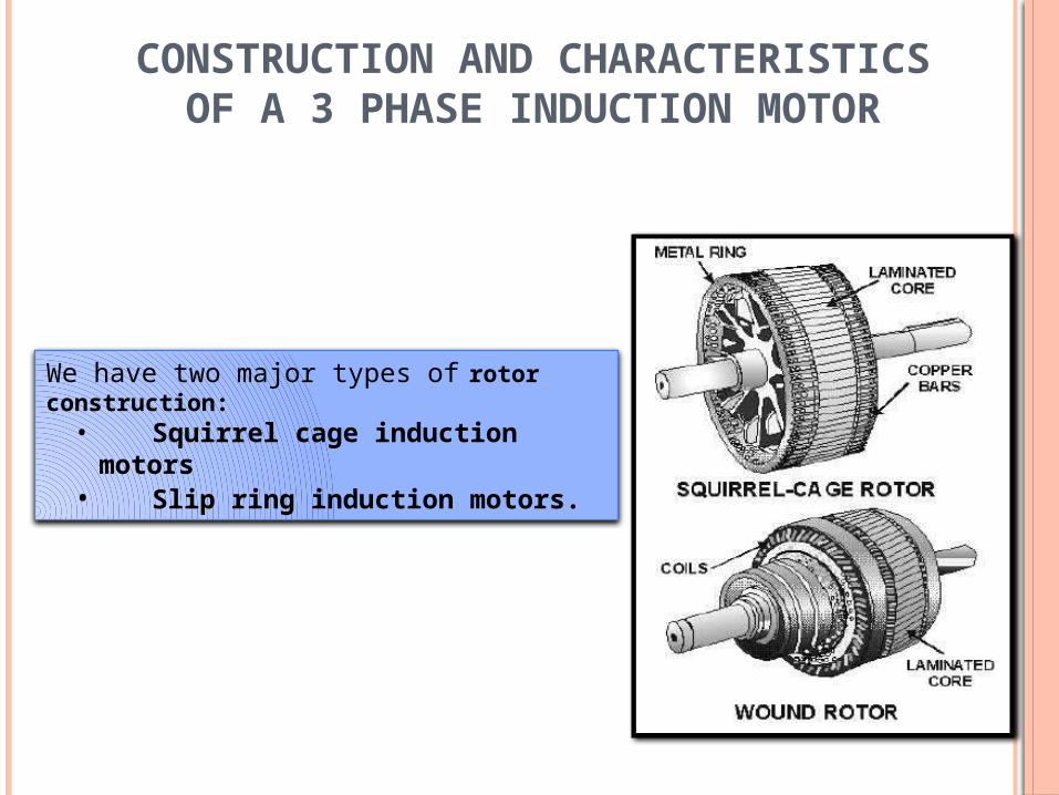
CONSTRUCTION AND CHARACTERISTICS OF A 3 PHASE INDUCTION MOTOR
We have two major types of rotor construction:• Squirrel cage induction motors• Slip ring induction motors.

DEMONSTRATION OF SQUIRREL CAGE MOTOR

CONSTRUCTION SQUIRREL CAGE ROTOR
The rotor of the squirrel cage motor contains no windingThe rotor is constructed of laminated steel sheets assembled around a shaft. The rotor winding consists of copper or aluminium bars and soldered to two copper end rings.The bars and end rings are all die cast in position without soldering at the ends. The conductor rotors more rugged. The slots of the rotor are not always parallel to the slots on the stator. Skewed rotors are twisted (skewed). Skew effectively reduces noise, eliminates the magnetic locking of the rotor and increases starting torque.Operates by virtue of the eddy currents established in the rotor. The speed performance of a squirrel cage motor is measured in terms of slip. Slip is usually expressed as the percentage by which the speed of the rotor falls behind the speed of the rotating synchronous speed of the stator field.


CHARACTERISTICS OF SQUIRREL CAGE ROTOR
The most important characteristic of the induction motor is the •speed •torque characteristic which is also called the mechanical characteristic
The characteristic of the squirrel cage induction motor to find the relationship between load, speed, torque and slip.
Speed, Torque and slip characteristic

SYNCHRONOUS SPEED
The speed at which the magnetic field rotates is known as the synchronous speed.
Methods of speed control By variation of frequency By variation of pole
Ns = 120f P
Ns : synchronous speed in rpm(revolution per minute)
P: number of poles in the stator

ROTOR SPEED
The induced rotor voltage UR is proportional to the slip s. In the stopped position, it peaks at n = 1 and s = 1This fact is confirmed in real-life applications by thehigh starting current (starting current inrush).The torque also peaks during the stop period at a certain rotor resistance.This behavior can be modified by design variation. However the rotor resistance is not usually used for this purpose.
The following formula applies to the rotor speed:
TORQUE
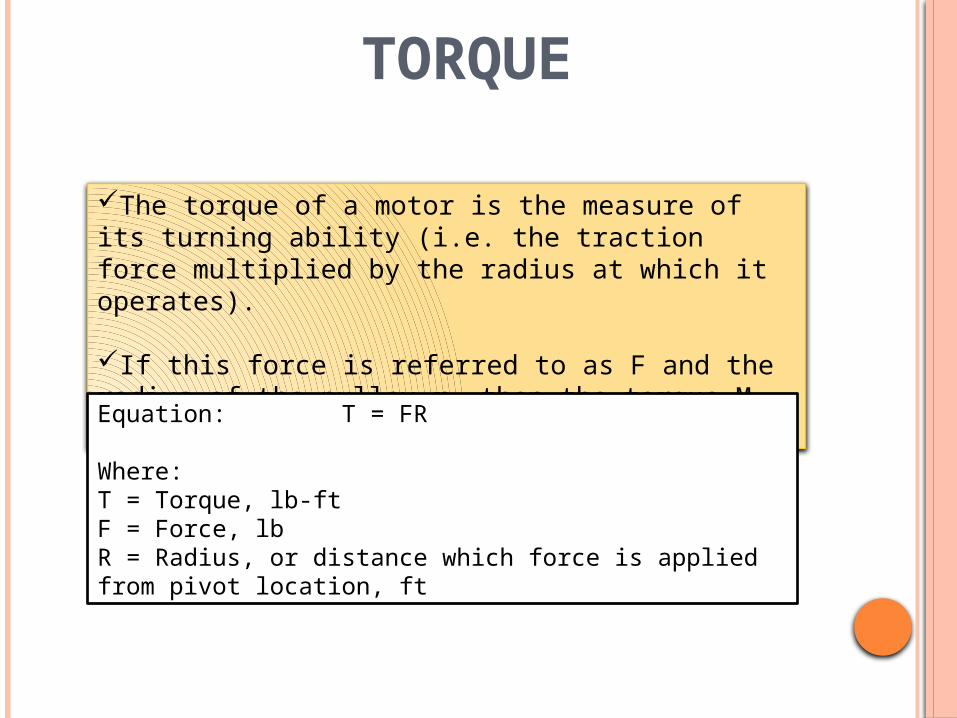
The torque of a motor is the measure of its turning ability (i.e. the traction force multiplied by the radius at which it operates).
If this force is referred to as F and the radius of the pulley r, then the torque M of the motor is given by:
Equation: T = FR
Where:T = Torque, lb-ftF = Force, lbR = Radius, or distance which force is applied from pivot location, ft

SLIP, S
•The rotor speed of an Induction machine is different from the speed of Rotating magnetic field. The % difference of the speed is called slip.
Where; ns = synchronous speed (rpm)
nr = mechanical speed of rotor (rpm)under normal operating conditions, s= 0.01 ~ 0.05, which is very small and the actual speed is very close to synchronous speed.Note that : s is not negligible
)1( snnORn
nns sr
s
rs

CHARACTERISTICS OF SQUIRREL CAGE ROTOR
Always lag behind the synchronous speed of the stator field.The rotor slip is necessary in order to induce the rotor currents required for the motor torqueThe torque will increase in almost direct proportion to the rotor slip The rotor speed will decrease when the slip is increase Increase in slip in turn increases the induced rotor currents, and the increased rotor current in turn, will produce a higher torque to meet the increased load.
EXPERIMENTS OF SQUIRREL CAGE ROTOR

APPLICATION OF SQUIRREL CAGE MOTOR
Migration pump sets

DEMONSTRATION SLIP-RING ROTOR

WORKING SLIP-RING ROTORThe stator-winding of the slip-ring motor is connected to the 3-phase supply produces a rotating magnetic.The brushes and the star-connected external resistors. The rotor resistance is high enabling the starting current to be lowThe high resistance rotor circuit increases the rotor power factorThe torque developed at the start becomes much higher than the torque developed in squirrel cage motors.The external resistance is slowly reduced, the motor operates with low slip and high operating efficiencyBy Increasing rotor resistance, the motor’s slip will be greater, the speed regulation poorer and it will have low efficiencyThe design of external resistance varied to change the speed of the slip- ring motor between 50 to 100 percent of the rated speed.The I2R loss in the rotor due to increased resistance is inevitable.

CONSTRUCTION SLIP-RING ROTOR
Variable speed and high starting torque are prime requirementsThe stator of the slip-ring induction motor is very much the sameStator windings can be either star or delta connected depending upon the designThe rotor consists of three-phase windings to form the same number of poles as in a statorThe rotor winding is connected in star and the open ends are connected to three slip-rings mounted in the rotor shaft

CHARACTERISTICS OF SLIP RING MOTOR
o Constant speed-service requiring a heavier starting torque than is obtainable with squirrel cage type.o Lower starting currento Insertion of higher external resistance alters the starting torque to a higher valueoExternal resistance improves the starting to torque to a higher valueoThe running efficiency of the motor could be achieved by cutting out the external resistance when the motor picks up its speed. oa higher starting torque and a variables speed control.

APPLICATION OF SLIP RING MOTOR
compressor Central air conditoining
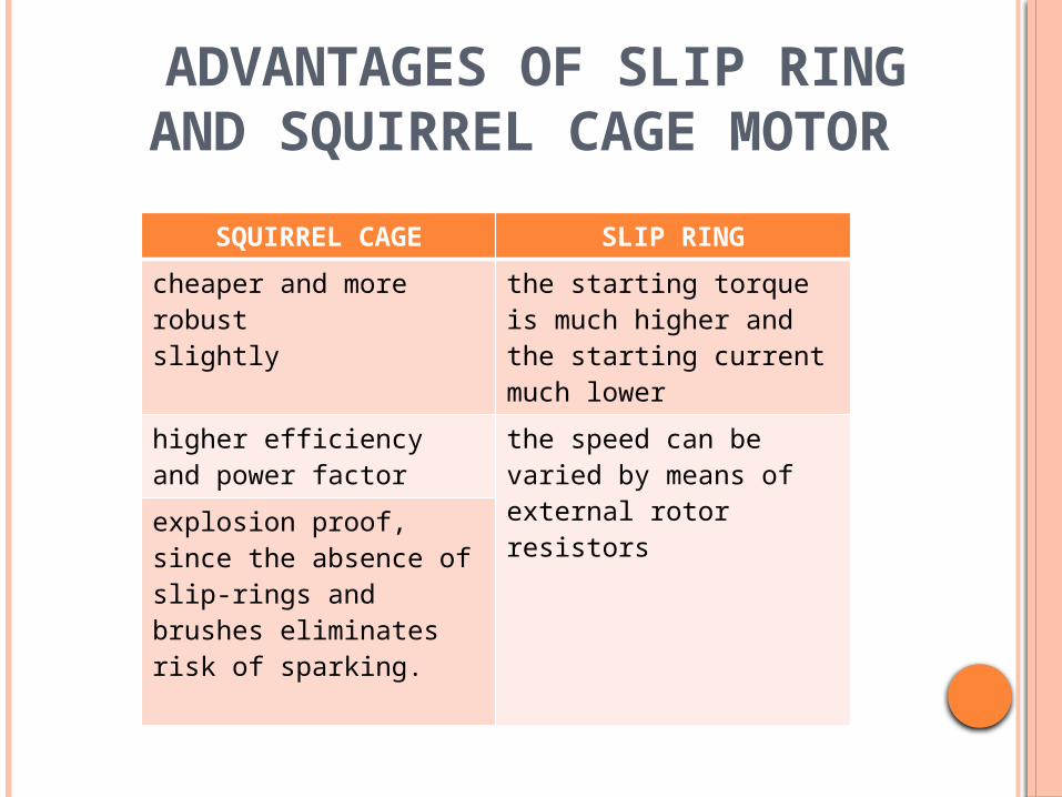
ADVANTAGES OF SLIP RING AND SQUIRREL CAGE MOTOR
SQUIRREL CAGE SLIP RING
cheaper and more robustslightly
the starting torque is much higher and the starting current much lower
higher efficiency and power factor
the speed can be varied by means of external rotor resistorsexplosion proof, since the
absence of slip-rings and brushes eliminates risk of sparking.

DOUBLE POLES SQUIRREL CAGE MOTOR??
There are 2 types that most marketable double speed squirrel cage motor :
• Two separate winding• Dahlender
The synchronous speed of the machine can be varied are:
•changing the electrical frequency which using the frequency inverter
•changing the number of poles on the motor
The rotor speed always remains near rotating magnetic fields speed or synchronous speed.
To vary the slip of the motor for given load

Dahlender Two separated winding

PRINCIPLE OF DOUBLE POLES MOTOR
Permit the synchronous speed to be changed by changing the number of stator poles
The synchronous speed will be reduced by one half
The number of stator poles can be changed by changing the direction of current flow through alternate pairs of poles.
Both poles will produce the same magnetic polarity and are essentially one pole.
The coils now produce the opposite magnetic polarities and are essentially two different poles

SINGLE PHASE MOTOR

04
/18
/20
23
Sin
gle
ph
ase
ind
uctio
n m
oto
r
35

SINGLE PHASE INDUCTION MOTOR
The single-phase induction machine is the most frequently used motor for refrigerators, washing machines, clocks, drills, compressors, pumps, and so forth.
The single-phase motor stator has a laminated iron core with two windings arranged perpendicularly.
One is the main and The other is the auxiliary winding or
starting winding

SINGLE PHASE INDUCTION MOTOR

SINGLE PHASE INDUCTION MOTOR
This “single-phase” motors are truly two-phase machines.
The motor uses a squirrel cage rotor, which has a laminated iron core with slots.
Aluminum bars are molded on the slots and short-circuited at
both ends with a ring.
Stator with laminatediron core Slots with winding
Bars
Ring to shortcircuit the barsStarting winding
+
_
Main winding
Rotor withlaminatediron core+
_
Figure 7.42 Single-phase induction motor.

SINGLE PHASE INDUCTION MOTOR
Figure 7.10 Squirrel cage rotor


UNIVERSAL MOTOR The operation of a universal motor is much like a series dc
motor. Force is created on the armature conductors due to the
interaction between the mian field flux The flux created by the current carring armature conductor. Develops unidirectional torque regardless of whether it
operated on AC or DC supply

o In AC operation, both field armature currents change their polarities and resulting unidirectional torque.
o Change the rotation of the motor by reversing the flow of current through either the armature or the field windings.

CHARACTERISTICS The speed of the motor is inversely proportional to
the load.(eg; low at full load) The speed reaches a dangerously high value due to
low field flux at no load. Are connected with permanent load or gear trains
to avoiding high speeds.

EXPERIMENTS

APPLICATIONS
Vacuum cleaner
Domestic sewing
machine

REPULSION MOTORS
Figure above show a two pole motor with its magnetic axis vertical.
The armature have a commutator which is short circuited through the brushes that placed in the magnetic field.
The stator winding connected to AC supply, it produces an alternating magnetic field.
A voltage is induced in rotor conductors by the transformer action.

o The direction of current according with Len’z law.
o Created a north pole at the top just below the stator north pole, and a south pole at the bottom just at the top of the stator south pole to oppose the induction action.
o No torque developed due to the absence of the tangential component of the torque
Lenz law An induced current flows in a direction to create a
magnetic field which will counteract the change in magnetic flux.
or An induced electromagnetic force generates a
current that induces a counter magnetic field that opposes the magnetic field generating the current.

CHARACTERISTIC
the current in the starting winding due to its capacitor will lead the applied voltage and line current in very small.
This result in producing a higher power factor and an excellent starting toque, several times higher than the normal running torque.
The running torque adjusts itself with load by varying inversely with respect to speed

APPLICATION
Due to the excellent starting torque and easy direction-reversal characteristic.
These machines are used in balted fans, blowers, dryers, washing machines, pumps and compressors.

PERMANENT CAPACITOR MOTOR
The starting torque is not required to be high at the same time elimination of the centrifugal switch in the motor
The capacitor connect in series with the starting winding
These capacitor should be of oil-type construction and have continuous duty rating
Below is the torque-speed characteristic

CAPACITOR START, CAPACITOR RUN MOTOR
Have excellent starting torque.About 300% of the full load torque, power
factor starting is high,When its running torque is not good,
power factor is low. Lesser efficiency

CHARACTERISTIC
The starting torque is 300% of the full load torque
The starting current is low , say 2 to 3 times of the running current
Highly efficient runningExtremely noiseless operationStarting and running P.F are goodLoad up to 125% of the full-load capaciy

APPLICATION
Air conditioner
refrigerators

THE END
QUESTION & ANSWER SESSION