pc hardware & booting - iit madras cse dept.chester/courses/15o_os/slides/3... ·...
TRANSCRIPT

PC Hardware & Booting
Chester Rebeiro
IIT Madras

22
Outline
• Memory and Device Addresses
• PC Organization
• x86 Evolution
• Powering up
• Booting xv6
• Multiprocessor booting

3
CPUs
Processori386
4
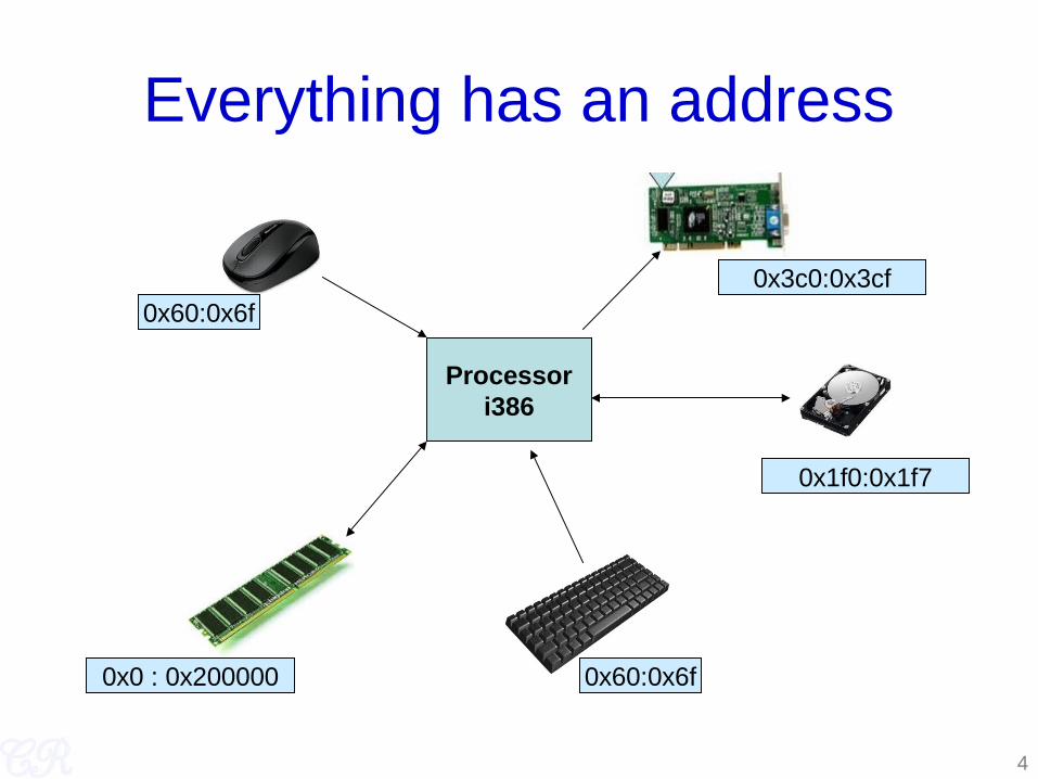
Everything has an address
Processori386
0x0 : 0x200000 0x60:0x6f
0x1f0:0x1f7
0x3c0:0x3cf0x60:0x6f

Address Types
• Memory Addresses
• IO Addresses
• Memory Mapped IO Addresses
5

6
Address Types : (Memory Addresses)
• Range : 0 to (RAM size or 232-1)
• Where main memory is mapped– Used to store data for code, heap, stack, OS, etc.
• Accessed by load/store instructions
Memory Map

7
Low and Extended Memory(Legacy Issues)
• Why study it? – Backward compatibility
• 8088 has 20 address lines; can address 220 bytes (1MB)• Memory Ranges
– 0 to 640KB used by IBM PC MSDOS• Other DOS versions have a different memory limit
– 640 KB to 1MB used by video buffers, expansion ROMS, BIOS ROMs
– 1 MB onwards called extended memory• Modern processors have more usable memory
– OSes like Linux and x86 simply ignore the first 1MB and load kernel in extended memory

8
Address Types : (IO Ports)
• Range : 0 to 216-1
• Used to access devices
• Uses a different bus compared to RAM memory access– Completely isolated from memory
• Accessed by in/out instructions
ref : http://bochs.sourceforge.net/techspec/PORTS.LST
inb $0x64, %aloutb %al, $0x64

9
Memory Mapped I/O
• Why?– More space
• Devices and RAM share the same address space
• Instructions used to access RAM can also be used to access devices.– Eg load/store
Memory Map

10
Who decides the address ranges?
• Standards / Legacy– Such as the IBM PC standard– Fixed for all PCs. – Ensures BIOS and OS to be portable across
platforms
• Plug and Play devices– Address range set by BIOS or OS– A device address range may vary every time the
system is restarted

11
PC OrganizationProcessor
1Processor
2Processor
3Processor
4
front side bus
North BridgeDRAM
South Bridge EthernetController
VGAPCI-PCIBridge
USB Controller
DMI busPCI Bus 0
MorePCI
devices
USBdevice
USBbridge
USBdevice
USBdevice
LegacyDevices PS2
(keyboard, mouse, PC speaker)
PCI Bus 1
Memory bus

12
The x86 Evolution (8088)
• 8088– 16 bit microprocessor– 20 bit external address bus
• Can address 1MB of memory– Registers are 16 bit
General Purpose Registers AX, BX, CD, DX,
Pointer Registers BP, SI, DI, SPInstruction Pointer : IPSegment Registers CS, SS, DS, ES
– Accessing memory (segment_base << 4) + offset eg: (CS << 4) + IP
General Purpose Registers
GPRs can be accessed as 8 bit or 16 bit registersEg. mov $0x1, %ah ; 8 bit move mov $0x1, %ax ; 16 bit move

13
The x86 Evolution (80386)
• 80386 (1995)– 32 bit microprocessor– 32 bit external address bus
• Can address 4GB of memory– Registers are 32 bit
General Purpose Registers EAX, EBX, ECD, EDX,
Pointer Registers EBP, ESI, EDI, ESPInstruction Pointer : IPSegment Registers CS, SS, DS, ES
– Lot more features• Protected operating mode• Virtual addresses
General Purpose Registers
GPRs can be accessed as 8, 16, 32 bit registerse.g. mov $0x1, %ah ; 8 bit move mov $0x1, %ax ; 16 bit move mov $0x1, %eax ; 32 bit move

14
The x86 Evolution (k8)
• AMD k8 (2003)– RAX instead of EAX
– X86-64, x64, amd64, intel64: all same thing
• Backward compatibility– All systems backward compatible with 8088
15
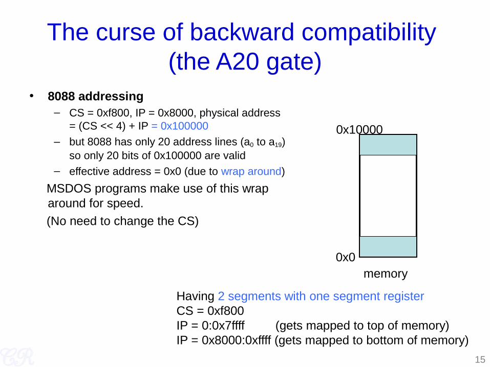
The curse of backward compatibility (the A20 gate)
• 8088 addressing– CS = 0xf800, IP = 0x8000, physical address
= (CS << 4) + IP = 0x100000
– but 8088 has only 20 address lines (a0 to a19) so only 20 bits of 0x100000 are valid
– effective address = 0x0 (due to wrap around)
MSDOS programs make use of this wrap around for speed.
(No need to change the CS)
memory0x0
0x10000
Having 2 segments with one segment registerCS = 0xf800 IP = 0:0x7ffff (gets mapped to top of memory)IP = 0x8000:0xffff (gets mapped to bottom of memory)

16
The curse of backward compatibility contd. (the A20 gate)
• 80386 addressing– CS = 0xf800, IP = 0x8000, physical
address = (CS << 4) + IP = 0x100000
– 80386 has 32 address lines (a0 to a31) therefore can access more than 1MB
– effective address is therefore 0x100000 and not 0.
• Not backward compatible to 8086
memory
0x0
0x10000
Having 2 segments with one segment register NOT FEASIBLE!!CS = 0xf800 IP = 0:0x7ffff (gets mapped below 1MB)IP = 0x8000:0xffff (gets mapped above 1MB)

17
The curse of backward compatibility contd. (the A20 gate)
• Have a gate (called A20 gate)– In real mode (8086 compatible mode) disable A20 to ensure wrap
around
– In protected mode (not 8086 compatible) enable A20 to allow full memory access.
• Implementing the gate– port 0x64 (part of keyboard I/O memory)
while(keyboard is busy);output 0xD1 to port 0x64while(keyboard is busy);output 0xDF to port 0x60

Powering Up
18
Power on Reset
reset
19
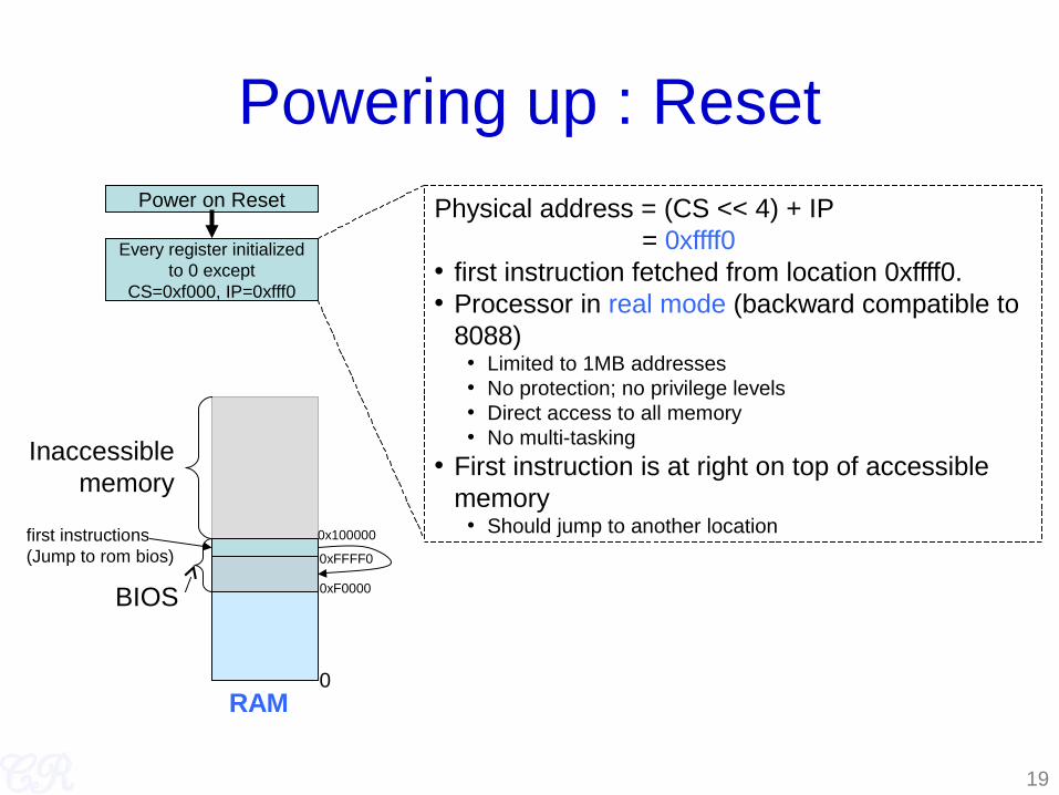
Powering up : ResetPower on Reset
Every register initializedto 0 except
CS=0xf000, IP=0xfff0
Physical address = (CS << 4) + IP = 0xffff0• first instruction fetched from location 0xffff0.• Processor in real mode (backward compatible to
8088)• Limited to 1MB addresses• No protection; no privilege levels• Direct access to all memory• No multi-tasking
• First instruction is at right on top of accessible memory
• Should jump to another location
Inaccessiblememory
BIOS
0
0x100000
0xFFFF0
0xF0000
first instructions(Jump to rom bios)
RAM

20
Powering up : BIOS
• Present in a small chip connected to the processor
– Flash/EPROM/E2PROM• Does the following
– Power on self test– Initialize video card and other devices– Display BIOS screen– Perform brief memory test– Set DRAM memory parameters– Configure Plug & Play devices– Assign resources (DMA channels & IRQs)– Identify the boot device
• Read sector 0 from boot device into memory location 0x7c00• Jumps to 0x7c00
Power on Reset
Every register initializedto 0 except
CS=0xf000, IP=0xfff0
BIOS

21
Powering up : MBR
• Sector 0 in the disk called Master Boot Record (MBR)• Contains code that boots the OS or another boot loader• Copied from disk to RAM (@0x7c00) by BIOS and then
begins to execute• Size 512 bytes
446 bytes bootable code 64 bytes disk partition information (16 bytes per partition) 2 bytes signature
• Typically, MBR code looks through partition table and loads the bootloader (such as Linux or Windows)
• or, it may directly load the OS
Power on Reset
Every register initializedto 0 except
CS=0xf000, IP=0xfff0
BIOS
MBR Execution

22
Powering Up : bootloaderPower on Reset
Every register initializedto 0 except
CS=0xf000, IP=0xfff0
BIOS
MBR Execution
Bootloader
• Loads the operating system – May also allow the user to select which OS to load
(eg. Windows or Linux)• Other jobs done
– Disable interrupts :• Don’t want to bother with interrupts at this stage• Interrupts re-enabled by xv6 when ready
– Setup GDT– Switch from real mode to protected mode– Read operating system from disk
The bootloader may be present in the MBR (sector 0) itself

23
Powering Up : OSPower on Reset
Every register initializedto 0 except
CS=0xf000, IP=0xfff0
BIOS
MBR Execution
Bootloader
• Set up virtual memory• Initialize interrupt vectors• Initilize
• timers, • monitors, • hard disks, • consoles, • filesystems,
• Initialized other processors (if any)• Startup user process
OS

24
Powering Up : xv6Power on Reset
Every register initializedto 0 except
CS=0xf000, IP=0xfff0
BIOS
Bootloader
OS
• Bootloader• Present in sector 0 of disk. • 512 bytes• 2 parts:
– bootasm.S (8900)• Enters in 16 bit real mode, leaves in 32 bit
protected mode• Disables interrupts
– We don’t want to use BIOS ISRs• Enable A20 line• Load GDT (only segmentation, no paging)• Set stack to 0x7c00• Invoke bootmain• Never returns
– bootmain.c (9017)• Loads the xv6 kernel from sector 1 to RAM
starting at 0x100000 (1MB)• Invoke the xv6 kernel entry
– _start present in entry.S (sheet 10)– This entry point is known from the ELF
header

Multiprocessor Organization
Processor1
Processor2
Processor3
Processor4
front side bus
North BridgeDRAMMemory bus
• Memory Symmetry• All processors in the system share the same memory space• Advantage : Common operating system code
• I/O Symmetry• All processors share the same I/O subsystem • Every processor can receive interrupt from any I/O device

26
Multiprocessor Booting
• One processor designated as ‘Boot Processor’ (BSP)– Designation done either by Hardware or BIOS – All other processors are designated AP (Application Processors)
• BIOS boots the BSP• BSP learns system configuration• BSP triggers boot of other AP
– Done by sending an Startup IPI (inter processor interrupt) signal to the AP
http://www.intel.com/design/pentium/datashts/24201606.pdf

xv6 Multiprocessor Boot
• mpinit (7001) invoked from main (1221)– Searches for an MP table in memory
• (generally put there by the BIOS)
• Contains information about processors in system along with other details such as IO-APICs, Processor buses, etc.
• Extracts system information from MP table
– Fills in the cpu id (7024)• CPU is a structure which contains CPU specific data (2304)
27

Booting APs
• startothers (1274) invoked from main(1237)– copy ‘entryother’ to location 0x7000
– For each CPU found• Allocate a stack (1295)
• Set C entry point to mpenter (1252)
• Send a Startup IPI (1299)– Pass the entryother.S location to the new processor (40:67 0x7000
>> 4)
– Send inter processor interrupt to the AP processor using its apicid
• Wait until CPU has started
28
for next class
• Read / revise about memory management in x86 especially– Segmentation (GDT)
– Virtual memory (page tables, CR3 register, etc)
29