pc360lc - komatsu
TRANSCRIPT

Photos may include optional equipment.
NET HORSEPOWER192 kW / 257 HP@1950 rpm
OPERATING WEIGHT35,950 – 37,440 kg
BUCKET CAPACITY0.53 – 1.80 m3
EPA Tier 4 Final Engine
PC360LC-11
Australia & New Zealand Specifications
HYDRAULIC EXCAVATOR

2
Photos may include optional equipment.
NET HORSEPOWER192 kW / 257 HP@1950 rpm
OPERATING WEIGHT35,950 – 37,440 kg
BUCKET CAPACITY0.53 – 1.80 m3
WALK-AROUND

PC360LC-11
3
Enhanced working environment • High back, heated air suspension seat with adjustable arm rests • Integrated ROPS cab design • Cab meets ISO Level 1 Operator Protective Guard (OPG) top guard • Auxiliary jack and (2) 12V power outlets
• Auto climate control
Komatsu designed and manufactured components
Handrails (standard) located on the machine upper structure provide a convenient work area in front of the engine.
Lockable single pole battery isolation switch allows a technician to disconnect the power supply before servicing the machine.
Heavy duty boom design with large one piece castings provide increased strength and durability.
Komatsu Auto Idle Shutdown helps reduce nonproductive engine idle time and reduces operating costs.
Operator Identification System records KOMTRAX® machine operation and application data for up to 100 individual ID codes.
A powerful Komatsu SAA6D114E-6 engine provides a net output of 192 kW 257 HP. This engine is EPA Tier 4 Final emissions certified.
Komatsu Variable Geometry Turbocharger (KVGT) uses a hydraulic actuator to provide optimum air flow under all speed and load conditions.
Komatsu Diesel Particulate Filter (KDPF) and Selective Catalytic Reduction (SCR) system reduce particulate matter and NOx while providing automatic regeneration that does not interfere with daily operation.
Large displacement high efficiency pumps provide high flow output at lower engine speed, improving efficiency.
Two boom mode settings provide power mode for maximum digging force or smooth mode for fine grading operations.
KOMTRAX® equipped machines can send location, SMR and operation maps to a secure website or smart phone utilising wireless technology. Machines also relay error codes, cautions, maintenance items, fuel & Diesel Exhaust Fluid (DEF) levels, and much more.
Large LCD colour monitor:
• 7" high resolution display • Enhanced hydraulic attachment control with one way/two way
flow and programmable work tool names and settings
• Key machine settings and controls easily accessible through the monitor
Rearview monitoring system (standard) with integrated camera display in the default monitor screen.
Six working modes are designed to match engine speed, pump delivery and system pressure to the application.
GREATER PERFORMANCE & FASTER CYCLE TIMESKomatsu's Closed-centre Load Sensing System (CLSS) provides quick response and smooth operation to maximise productivity.
New engine and hydraulic control technology improves operational efficiency and lowers fuel consumption by up to 11%

KOMATSUNEWENGINETECHNOLOGIES☺
New regulations effective in 2018 require the reduction of NOx emissions to one tenth or below from the preceding regulations. In addition to refining the Tier 4 Interim technologies, Komatsu has developed a new Selective Catalytic Reduction (SCR) device in-house.
Heavy-duty cooled Exhaust Gas Recirculation (EGR) systemThe system recirculates a portion of exhaust gas into the air intake and lowers combustion temperatures, thereby reducing NOx emissions. EGR gas flow has beendecreased for Tier 4 Final with the addition of SCR technology. The system achieves a dynamic reduction of NOx, while helping reduce fuel consumption below Tier 4 Interim levels.
Technologies Applied to New EngineHeavy-duty aftertreatment systemThis new system combines a Komatsu Diesel ParticulateFilter (KDPF) and Selective Catalytic Reduction (SCR). The SCR NOx reduction system injects the correct amount of Diesel Exhaust Fluid (DEF) at the proper rate, thereby decomposing NOx into non-toxic water vapour (H2O) and nitrogen gas (N2).
Advanced Electronic Control SystemThe electronic control system performs high-speed processing of all signals from sensors installed in the vehicle providing total control of equipment in all conditions of use. Engine condition information is displayed via an on-board network to the monitor inside the cab, providing necessary information to the operator. Additionally, managing the information via KOMTRAX helps customers keep up with required maintenance.
Komatsu Variable Geometry Turbocharger (KVGT) systemThe VGT system features proven Komatsu design hydraulic technology for variable control of air-flow and supplies optimal air according to load conditions. The upgraded version provides better exhaust temperature management.
KDPFDEF mixing tube
Clean exhaust
Ammonia oxidation catalyst
Secondary selective reduction catalyst for NOx
Primary selective reduction catalyst for NOx
KCCV
VGT
KDPF
DEF SCR
Cooled EGR
PERFORMANCE FEATURES
Komatsu’s New Emission Regulations-compliant Engine
4
5
PC360LC-11
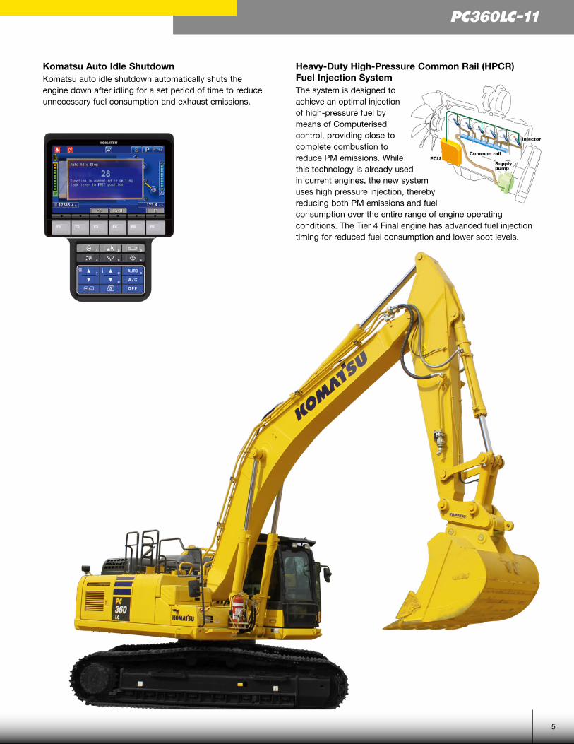
Komatsu Auto Idle ShutdownKomatsu auto idle shutdown automatically shuts the engine down after idling for a set period of time to reduce unnecessary fuel consumption and exhaust emissions.
Heavy-Duty High-Pressure Common Rail (HPCR) Fuel Injection SystemThe system is designed to achieve an optimal injection of high-pressure fuel by means of Computerised control, providing close to complete combustion to reduce PM emissions. While this technology is already used in current engines, the new system uses high pressure injection, thereby reducing both PM emissions and fuel consumption over the entire range of engine operating conditions. The Tier 4 Final engine has advanced fuel injection timing for reduced fuel consumption and lower soot levels.

Reduced Fuel ConsumptionThe PC360LC-11's new tier 4 final engine along with enhancements in the hydraulic system considerably decreases fuel consumption.
Fuel Consumption
Reduced by 11% (vs PC350LC-8M0 Based on typical work pattern collected via KOMTRAX)
This fuel consumption data is the result compared actual measured value using the prototype machine.
Increased Work EfficiencyLarge digging forceWith the one-touch Power Max. function, digging force is increased for 8.5 seconds of operation.
160 kN(16.3t) 171 kN(17.4t) 7% UP
213 kN(21.7t) 228 kN(23.2t) 7% UP
Maximum arm crowd force (ISO)
Maximum bucket digging force (ISO)
(With Power Max.)
(With Power Max.)
Measured with Power Max. function, 3200 mm arm and ISO rating
Faster arm cycle speedsTwo return hoses improve arm cylinder hydraulic flow for faster arm out performance.
Two-mode settings for boom• Smooth boom mode reduces boom down force for working on hard surfaces or for hydraulic hammer operation.• Power boom mode maximises digging force for more effective excavating
Lifting mode
When the Lifting mode is selected, lifting capacity is increased 7% by raising hydraulic pressure.
PERFORMANCE FEATURES
6
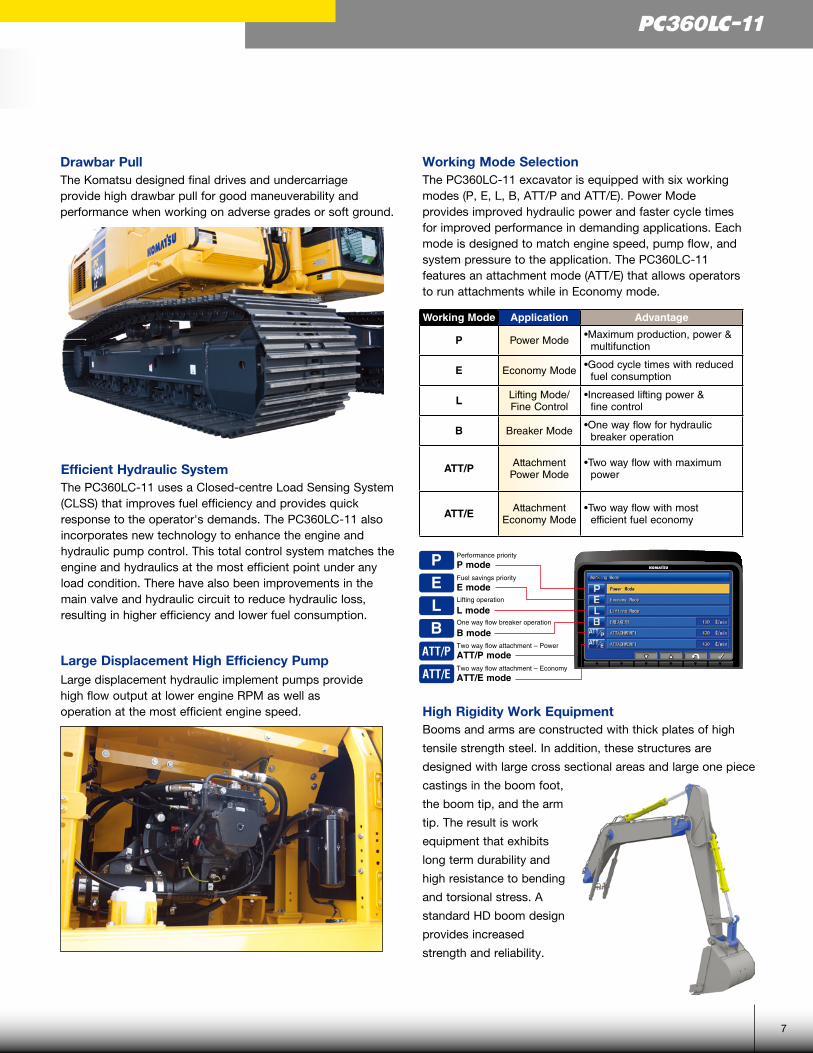
Drawbar PullThe Komatsu designed final drives and undercarriage provide high drawbar pull for good maneuverability and performance when working on adverse grades or soft ground.
Working Mode SelectionThe PC360LC-11 excavator is equipped with six working modes (P, E, L, B, ATT/P and ATT/E). Power Mode provides improved hydraulic power and faster cycle times for improved performance in demanding applications. Each mode is designed to match engine speed, pump flow, and system pressure to the application. The PC360LC-11 features an attachment mode (ATT/E) that allows operators to run attachments while in Economy mode.
PELB
ATT/P
ATT/E
Performance priority
P modeFuel savings priority
E modeLifting operation
L modeOne way flow breaker operation
B modeTwo way flow attachment – Power
ATT/P modeTwo way flow attachment – Economy
ATT/E mode
Large Displacement High Efficiency PumpLarge displacement hydraulic implement pumps providehigh flow output at lower engine RPM as well asoperation at the most efficient engine speed. High Rigidity Work Equipment
Booms and arms are constructed with thick plates of high
tensile strength steel. In addition, these structures are
designed with large cross sectional areas and large one piece
castings in the boom foot,
the boom tip, and the arm
tip. The result is work
equipment that exhibits
long term durability and
high resistance to bending
and torsional stress. A
standard HD boom design
provides increased
strength and reliability.
Working Mode Application Advantage
P Power Mode • Maximum production, power & multifunction
E Economy Mode • Good cycle times with reduced fuel consumption
L Lifting Mode/Fine Control
• Increased lifting power & fine control
B Breaker Mode • One way flow for hydraulic breaker operation
ATT/P Attachment Power Mode
• Two way flow with maximum power
ATT/E Attachment Economy Mode
• Two way flow with most efficient fuel economy
Efficient Hydraulic System The PC360LC-11 uses a Closed-centre Load Sensing System (CLSS) that improves fuel efficiency and provides quick response to the operator's demands. The PC360LC-11 also incorporates new technology to enhance the engine and hydraulic pump control. This total control system matches the engine and hydraulics at the most efficient point under any load condition. There have also been improvements in the main valve and hydraulic circuit to reduce hydraulic loss, resulting in higher efficiency and lower fuel consumption.
7
PC360LC-11

WORKING ENVIRONMENT
8

Comfortable Working SpaceWide spacious cabWide spacious cab includes seat with reclining backrest. The seat height and longitudinal inclination are easily adjusted using a pull-up lever. You can set the appropriate operational posture of armrest together with the console. Reclining the seat further enables you to place it into the fully flat state with the headrest attached.
Arm rest with simple height adjustment functionThe addition of a knob and a plunger to the armrest permits the height of the armrest to be easily adjusted without the use of tools.
Low vibration with cab damper mounting Automatic climate control Pressurised cab Auxiliary input jackConnecting a regular audiodevice to the auxiliary jackallows the operator to hearthe sound from the speakersinstalled in the cab.
Defroster (conforms to the ISO standard)
Standard Equipment
One-touch storable front window lower glass
Sliding window glass (left side)
Remote intermittent wiper with windshield washer
ISO Level 2 OPG
AM/FM stereo radio
Emergency stop & level indicator
Magazine box & cup holder
9
PC360LC-11
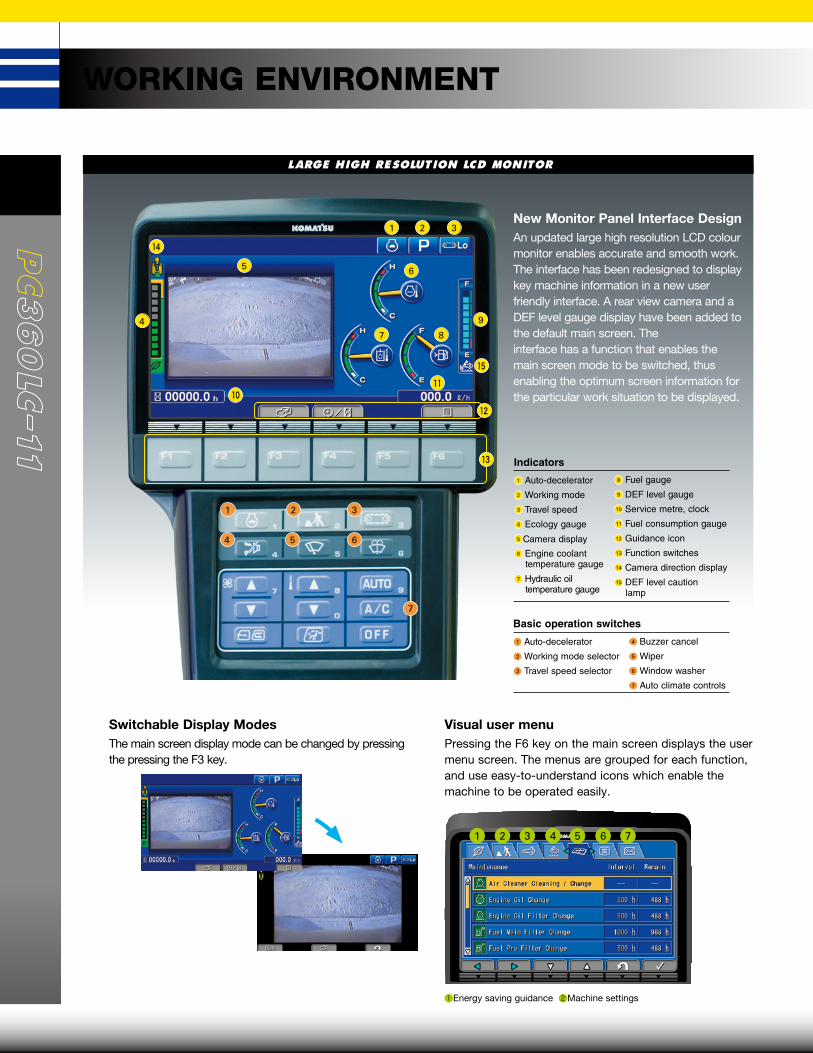
LARGE HIGH RESOLUTION LCD MONITOR
Energy saving guidance Machine settingsAftertreatment devices regeneration SCR informationMaintenance Monitor setting Message check
Visual user menuPressing the F6 key on the main screen displays the usermenu screen. The menus are grouped for each function,and use easy-to-understand icons which enable themachine to be operated easily.
Switchable Display ModesThe main screen display mode can be changed by pressing the pressing the F3 key.
1 32 4 5 76
New Monitor Panel Interface DesignAn updated large high resolution LCD colour monitor enables accurate and smooth work. The interface has been redesigned to display key machine information in a new user friendly interface. A rear view camera and a DEF level gauge display have been added to the default main screen. The interface has a function that enables the main screen mode to be switched, thus enabling the optimum screen information for the particular work situation to be displayed.
1
4 5 6
2 3
Indicators
1 Auto-decelerator
2 Working mode
3 Travel speed
4 Ecology gauge
5 Camera display6 Engine coolant
temperature gauge
7 Hydraulic oil temperature gauge
8 Fuel gauge
9 DEF level gauge
10 Service metre, clock
11 Fuel consumption gauge
12 Guidance icon
13 Function switches
14 Camera direction display
15 DEF level caution lamp
Basic operation switches
1 Auto-decelerator
2 Working mode selector
3 Travel speed selector
4 Buzzer cancel
5 Wiper
6 Window washer
7 Auto climate controls
4
5 6
1 2 3
7 8
9
WORKING ENVIRONMENT
7
10
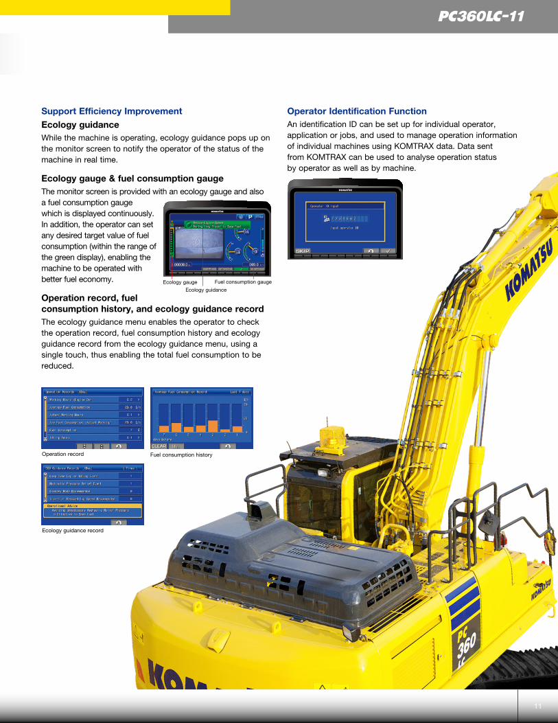
Support Efficiency ImprovementEcology guidanceWhile the machine is operating, ecology guidance pops up on the monitor screen to notify the operator of the status of the machine in real time.
Ecology gauge & fuel consumption gaugeThe monitor screen is provided with an ecology gauge and alsoa fuel consumption gaugewhich is displayed continuously. In addition, the operator can set any desired target value of fuel consumption (within the range of the green display), enabling the machine to be operated with better fuel economy.
Operation record, fuel consumption history, and ecology guidance recordThe ecology guidance menu enables the operator to check the operation record, fuel consumption history and ecology guidance record from the ecology guidance menu, using a single touch, thus enabling the total fuel consumption to be reduced.
Operator Identification FunctionAn identification ID can be set up for individual operator, application or jobs, and used to manage operation information of individual machines using KOMTRAX data. Data sent from KOMTRAX can be used to analyse operation status by operator as well as by machine.
Fuel consumption historyOperation record
Ecology guidance record
Ecology gauge Fuel consumption gauge
Ecology guidance
11
PC360LC-11

MAINTENANCE FEATURES
12

MAINTENANCE INFORMATION
Manual Stationary RegenerationUnder most conditions, active regeneration will occur automatically with no effect on machine operation. In case the operator needs to disable active regeneration or initiate a manual stationary regeneration, this can be easily accomplished through the monitor panel. A soot level indicator is displayed to show how much soot is trapped in the KDPF.
“Maintenance time caution lamp” displayWhen the remaining time to maintenance becomes less than30 hours*, a maintenance time monitor appears. Pressingthe F6 key switches the monitor to the maintenance screen.* : The setting can be changed within the range between 10 and 200 hours.
Maintenance screen
Supports the DEF level and refill timingThe DEF level gauge is displayed continuously on the right side of the monitor screen. In addition, when DEF level is low, DEF low level guidance messages appear in pop up displays to inform the operator in real time.
DEF low level guidanceDEF level gauge
Aftertreatment device regeneration screen
Soot level indicator
DT-type connectorsSealed DT-type electrical connectors provide high reliability, water and dust resistance. Waterproof seal
Waterproof sealWaterproof seal
Diesel Exhaust Fluid(DEF) tankA large tank volume extendsoperating time beforerefilling and is installed on the right front platform for easy access. DEF tank and pump are separated for improved service access.
Engine AccessLarge rear opening hood provides excellent maintenance and service access to key engine components.
Fuel FiltersLarge high-efficiency fuel filter and pre-filter with water separator removes contaminants from fuel for improved fuel injection system life.
High efficiency fuel filter
Fuel pre-filter (with water separator)
Easy access to engine oil filter and fuel drain valveEngine oil filter and fuel drain valve are remote mounted to improve accessibility.
Battery isolation switchA standard battery isolation switch allows a technician to disconnect the power supply and lock out before servicing the machine.
Air conditioner filterThe air conditioner filter can be removed and installedwithout the use of tools for easy filter maintenance.
Washable cab floormat
Sloping track frame
Long-life oils, filters
Engine oil & Engine oil filter every 500 hours
Hydraulic oil every 5000 hours
Hydraulic oil filter every 1000 hours
Large capacity air cleanerThe larger air cleaner can extend air cleaner life during long-term operation and helps prevent early clogging, and resulting power loss. A radial seal design is used for reliability.
13
PC360LC-11

ROPS CAB STRUCTURE
ROPS Cab (ISO 12117-2) The machine is equipped with aROPS cab that conforms to ISO12117-2 for excavators as standardequipment. It also satisfies therequirements for Level 1 OperatorProtective Guard (OPG) and topguard (ISO 10262).
GENERAL FEATURES
Secondary engine shut down switch at base of seat to shutdown the engine.
Lock lever
Retractable seat belt
Tempered & tinted glass
Large cab entrance step
Left and right side hand rails
Seat belt caution indicator
Large mirrors
Slip-resistant plates
Thermal and fan guards
Pump/engine compartment partition
Travel alarm
Rear view image on monitor
Rear View Monitoring SystemA new rear view monitoring system display has a rear viewcamera image that is continuously displayed together withthe gauges and important vehicle information. This enables theoperator to carry out work while easily checking thesurrounding area.
Rear view camera
Low Vibration with Viscous Cab MountsThe PC360LC-11 uses viscous mounts for the cab thatincorporate a longer stroke and the addition of a spring.The cab damper mounting combined with a high rigiditydeck reduces vibration at the operator’s seat.
Rubber
SiliconOil
Spring
GENERAL FEATURES
14
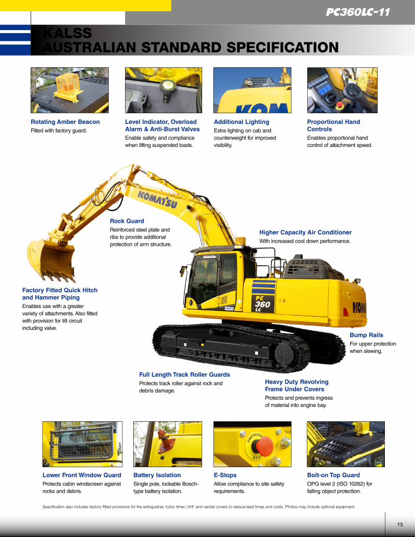
Factory Fitted Quick Hitch and Hammer PipingEnables use with a greater variety of attachments. Also fitted with provision for tilt circuit including valve.
Lower Front Window GuardProtects cabin windscreen against rocks and debris.
Level Indicator, Overload Alarm & Anti-Burst ValvesEnable safety and compliance when lifting suspended loads.
Battery IsolationSingle pole, lockable Bosch-type battery isolation.
Additional LightingExtra lighting on cab and counterweight for improved visibility.
E-StopsAllow compliance to site safety requirements.
Bolt-on Top GuardOPG level 2 (ISO 10262) for falling object protection.
Specification also includes factory fitted provisions for fire extinguisher, turbo timer, UHF and vandal covers to reduce lead times and costs. Photos may include optional equipment.
Rotating Amber BeaconFitted with factory guard.
Proportional Hand ControlsEnables proportional hand control of attachment speed.
Higher Capacity Air ConditionerWith increased cool down performance.
Heavy Duty Revolving Frame Under CoversProtects and prevents ingress of material into engine bay.
Bump RailsFor upper protection when slewing.
Full Length Track Roller GuardsProtects track roller against rock and debris damage.
Rock GuardReinforced steel plate and ribs to provide additional protection of arm structure.
KALSSAUSTRALIAN STANDARD SPECIFICATION
15
PC360LC-11
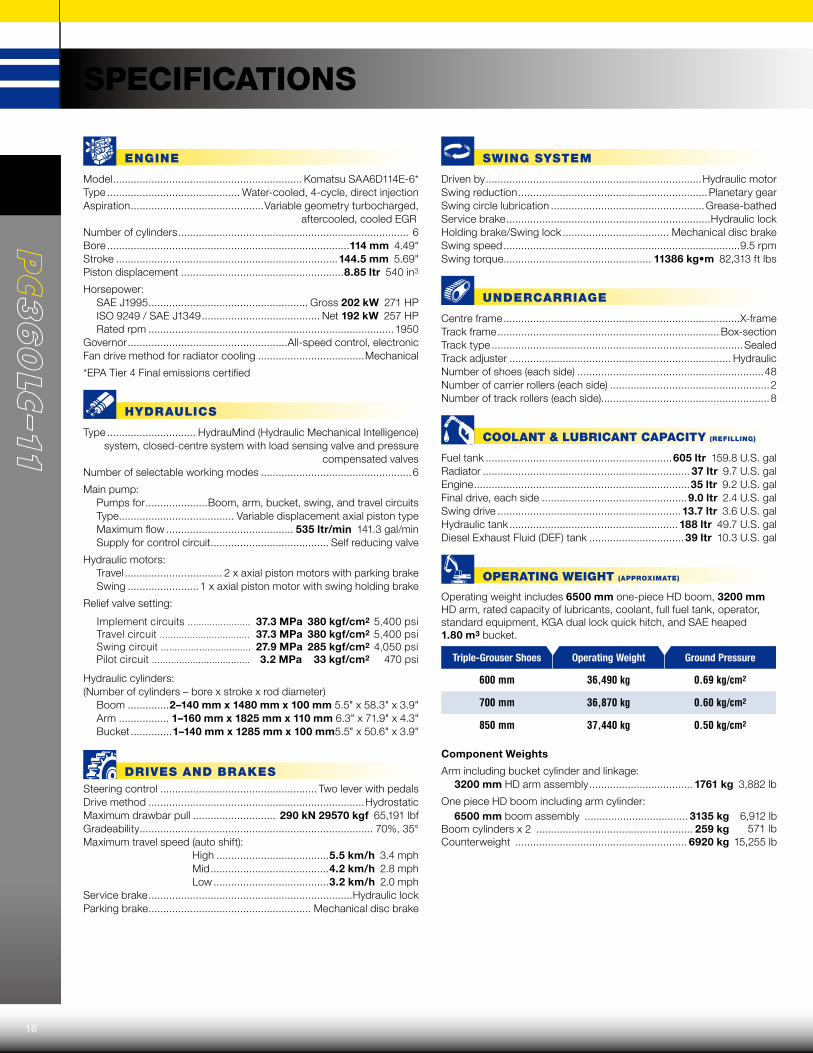
SPECIFICATIONS
ENGINE
Model ................................................................ Komatsu SAA6D114E-6*Type ............................................. Water-cooled, 4-cycle, direct injectionAspiration .............................................Variable geometry turbocharged, aftercooled, cooled EGRNumber of cylinders .............................................................................. 6Bore ..................................................................................114 mm 4.49"Stroke ...........................................................................144.5 mm 5.69"Piston displacement .......................................................8.85 ltr 540 in3
Horsepower: SAE J1995 ...................................................... Gross 202 kW 271 HP ISO 9249 / SAE J1349 ........................................ Net 192 kW 257 HP Rated rpm ................................................................................... 1950Governor ......................................................All-speed control, electronicFan drive method for radiator cooling ....................................Mechanical
*EPA Tier 4 Final emissions certified
HYDRAULICS
Type .............................. HydrauMind (Hydraulic Mechanical Intelligence)system, closed-centre system with load sensing valve and pressure
compensated valves Number of selectable working modes ...................................................6
Main pump: Pumps for .....................Boom, arm, bucket, swing, and travel circuits Type ....................................... Variable displacement axial piston type Maximum flow ........................................... 535 ltr/min 141.3 gal/min Supply for control circuit ........................................ Self reducing valve
Hydraulic motors: Travel ................................. 2 x axial piston motors with parking brake Swing ........................ 1 x axial piston motor with swing holding brake
Relief valve setting:
Implement circuits ....................... 37.3 MPa 380 kgf/cm2 5,400 psiTravel circuit ................................. 37.3 MPa 380 kgf/cm2 5,400 psiSwing circuit ................................. 27.9 MPa 285 kgf/cm2 4,050 psiPilot circuit .................................... 3.2 MPa 33 kgf/cm2 470 psi
Hydraulic cylinders:(Number of cylinders – bore x stroke x rod diameter) Boom ..............2–140 mm x 1480 mm x 100 mm 5.5" x 58.3" x 3.9" Arm ................. 1–160 mm x 1825 mm x 110 mm 6.3" x 71.9" x 4.3" Bucket ..............1–140 mm x 1285 mm x 100 mm5.5" x 50.6" x 3.9"
DRIVES AND BRAKESSteering control ..................................................... Two lever with pedalsDrive method .........................................................................HydrostaticMaximum drawbar pull ............................ 290 kN 29570 kgf 65,191 lbfGradeability ............................................................................... 70%, 35°Maximum travel speed (auto shift): High ......................................5.5 km/h 3.4 mph Mid ........................................4.2 km/h 2.8 mph Low .......................................3.2 km/h 2.0 mphService brake .....................................................................Hydraulic lockParking brake ....................................................... Mechanical disc brake
SWING SYSTEM
Driven by .........................................................................Hydraulic motorSwing reduction ................................................................Planetary gearSwing circle lubrication ....................................................Grease-bathedService brake .....................................................................Hydraulic lockHolding brake/Swing lock .................................... Mechanical disc brakeSwing speed ................................................................................9.5 rpmSwing torque .................................................. 11386 kg•m 82,313 ft lbs
UNDERCARRIAGE
Centre frame ................................................................................X-frame Track frame ........................................................................... Box-sectionTrack type .....................................................................................Sealed Track adjuster ........................................................................... HydraulicNumber of shoes (each side) ...............................................................48Number of carrier rollers (each side) ......................................................2Number of track rollers (each side).........................................................8
COOLANT & LUBRICANT CAPACITY (REFILLING)
Fuel tank ...............................................................605 ltr 159.8 U.S. galRadiator ...................................................................... 37 ltr 9.7 U.S. galEngine .........................................................................35 ltr 9.2 U.S. galFinal drive, each side .................................................9.0 ltr 2.4 U.S. galSwing drive ..............................................................13.7 ltr 3.6 U.S. galHydraulic tank ......................................................... 188 ltr 49.7 U.S. galDiesel Exhaust Fluid (DEF) tank ................................ 39 ltr 10.3 U.S. gal
OPERATING WEIGHT (APPROXIMATE)
Operating weight includes 6500 mm one-piece HD boom, 3200 mm HD arm, rated capacity of lubricants, coolant, full fuel tank, operator, standard equipment, KGA dual lock quick hitch, and SAE heaped 1.80 m3 bucket.
Triple-Grouser Shoes Operating Weight Ground Pressure
600 mm 36,490 kg 0.69 kg/cm2
700 mm 36,870 kg 0.60 kg/cm2
850 mm 37,440 kg 0.50 kg/cm2
Component Weights
Arm including bucket cylinder and linkage: 3200 mm HD arm assembly ................................... 1761 kg 3,882 lb
One piece HD boom including arm cylinder:6500 mm boom assembly ................................... 3135 kg 6,912 lb
Boom cylinders x 2 ..................................................... 259 kg 571 lbCounterweight .......................................................... 6920 kg 15,255 lb
16

* : Including grouser height ** : Including handrail
Arm Length 3200 mm
A Overall length 11145 mm
B Length on ground (transport) 5935 mm
C Overall height (to top of boom)* 3285 mm
D Overall width 3190 mm
E Overall height (to top of cab)* 3160 mm
F Overall height (to top of handrail)* 3255 mm
G Ground clearance, counterweight 1185 mm
H Ground clearance, minimum 498 mm
I Tail swing radius 3445 mm
J Track length on ground 4030 mm
K Track length 4955 mm
L Track gauge 2590 mm
M Width of crawler 3190 mm
N Shoe width 600 mm
O Grouser height 36 mm
P Machine height to top of engine cover 3135 mm
Q Machine upper width ** 3145 mm
R Distance, swing centre to rear end 3405 mm
I
NH
CE
RA
D,M
LJ O
G
P
K
B
Q
F
DIMENSIONS
345678910
5
6
7
8
9
1011
(m)
1112(m)
2
G.L.
2 1 0
-7
-6
-5
-4
-3
-2
-1
01
3
4
-8
H
A
C
B
ED
G
F
WORKING RANGE
Arm Length 3200 mm
A Max. digging height 10210 mm
B Max. dumping height 7110 mm
C Max. digging depth 7380 mm
D Max. vertical wall digging depth 6480 mm
E Max. digging depth for 8' level bottom 7180 mm
F Max. digging reach 11100 mm
G Max. digging reach at ground level 10920 mm
H Min. swing radius 4310 mm
SAE
ratin
g Bucket digging force at power max. 200 kN20400 kg
Arm crowd force at power max. 165 kN16800 kg
ISO
ratin
g Bucket digging force at power max. 228 kN23200 kg
Arm crowd force at power max. 171 kN17400 kg
17
PC360LC-11
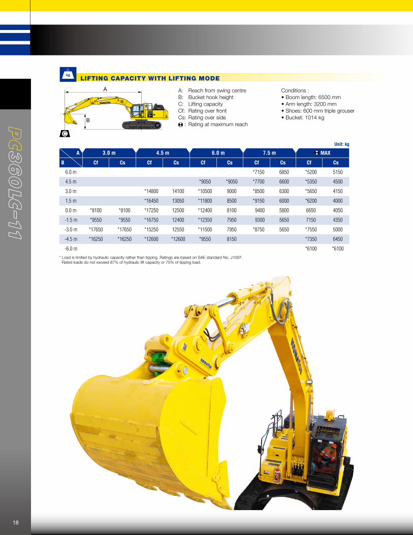
Unit: kg
A 3.0 m 4.5 m 6.0 m 7.5 m MAX
B Cf Cs Cf Cs Cf Cs Cf Cs Cf Cs
6.0 m *7150 6850 *5200 5150
4.5 m *9050 *9050 *7700 6600 *5350 4500
3.0 m *14800 14100 *10500 9000 *8500 6300 *5650 4150
1.5 m *16450 13050 *11800 8500 *9150 6000 *6200 4000
0.0 m *8100 *8100 *17250 12500 *12400 8100 9400 5800 6650 4050
-1.5 m *9550 *9550 *16750 12400 *12350 7950 9300 5650 7150 4350
-3.0 m *17650 *17650 *15250 12550 *11500 7950 *8750 5650 *7550 5000
-4.5 m *16250 *16250 *12600 *12600 *9550 8150 *7350 6450
-6.0 m *6100 *6100* Load is limited by hydraulic capacity rather than tipping. Ratings are based on SAE standard No. J1097.
Rated loads do not exceed 87% of hydraulic lift capacity or 75% of tipping load.
LIFT CAPACITIES
A: Reach from swing centreB: Bucket hook height C: Lifting capacityCf: Rating over frontCs: Rating over side
: Rating at maximum reach
Conditions :• Boom length: 6500 mm• Arm length: 3200 mm• Shoes: 600 mm triple grouser• Bucket: 1014 kg
A
B
C
LIFTING CAPACITY WITH LIFTING MODE
18

STANDARD EQUIPMENT
Autogrease system Battery isolation switch, dual pole, lockable Belly plates, 8 mm Cab guard
– Full front guard, OPG Level 2 Cab vandal guard set
Canvas seat cover Fire extinguisher, 1.5 kg Fire extinguisher, 4.5 kg Fire extinguisher, 9 kg Fuel cap vandal guard Jump start receptacle Radio, multimedia system
Radio, UHF Starter circuit isolation, lockable Track shoes, triple grouser, 700 mm Track shoes, triple grouser, 850 mm Turbo timer Window tinting
OPTIONAL EQUIPMENT
3 speed travel with auto shift Alternator, 90 A, 24V AM/FM radio Arm, 3200 mm Auto idle Auto idle shut down Automatic air conditioner, large capacity Automatic engine warm-up system Auxiliary input (3.5 mm jack) Batteries, large capacity Battery isolation switch, lockable Boom, 6500 mm Boom and arm burst valve protection Bump rails Cab guards
– Lower front window guard – Integrated top guard, OPG Level 1 – Bolt on top guard, OPG Level 2 Carrier rollers, (2 each side) Converter, (2) x 12 V Counterweight, 6920 kg Dry type air cleaner, double element Dual flow hammer piping Electric horn Emergency stops (3) EMMS monitoring system
Engine, Komatsu SAA6D114E-6 Engine overheat prevention system Fan guard structure Fuel system pre-filter 10 micron Grease sealed track chain High back air suspension seat, with heat High pressure in-line hydraulic filters Hydraulic track adjusters Hydraumind closed centre load sensing
system KOMTRAX Level 5.0 Large LCD colour monitor, high resolution Level indicator Lock lever Lock lever, auto lock Mirrors (LH, RH & sidewise) Operator identification system Overload alarm Power maximising system PPC hydraulic control system Proportional control handles Provision for tilt circuit, including valve Pump/engine room partition cover Quick hitch piping with safety switch and alarm
Radiator and oil cooler dustproof net
Rear reflectors Rearview monitoring system (1 camera) Revolving frame undercovers, heavy duty ROPS cab (ISO 12117-2) with vandal guard provisions
Rotating beacon with guard Seat belt indicator Seat belt, retractable, 78 mm Secondary engine shutdown switch Side by side coolers Slip resistant foot plates Starter motor, 11 kW/24 V x 1 Suction fan Thermal and fan guards Track frame swivel guard Track roller guards, full length Track rollers, 8 each side Track shoes, triple grouser, 600 mm Travel alarm Two boom mode setting Working lights
– 1 x boom – 1 x RH – 3 x cab – 1 x counterweight Working mode selection system
COMING SOON
KOMATSU JMHB360H-1 Hydraulic Breaker
Working weight kg 2,571
Oil flow (min - max) /min 175 - 250
Operating pressure (max) MPa 155
Impact rate bpm 320 - 560
Chisel diameter mm 160
Variable frequencies - 2 Auto
Acceptable back pressure bar 25
Base machine (min - max) Ton 27 - 40
Model Type JMHB360H-1
For a complete list of available attachments, please contact your local Komatsu representative.
Bucket, general purpose, KGA 650 mm, 0.53 m3
Bucket, general purpose, KGA 1300 mm, 1.35 m3
Bucket, general purpose, KGA 1500 mm, 1.61 m3
Bucket, general purpose, KGA 1700 mm, 1.80 m3
Bucket, rock, direct pin, KGA 1600 mm, 1.66 m3
Bucket, slope finishing, KGA 2200 mm, 2.20 m3
Quick hitch, KGA, dual lock Ripper, KGA, single tyne
ATTACHMENT OPTIONS
19
PC360LC-11

Form No: ZESS005500_SEPTEMBER2018
www.Komatsu.com.au Printed in Australia
Materials and specifications are subject to change without notice. is a trademark of Komatsu Ltd. Japan.