pce-d122 series programming manual - and ethercat · 2015-11-17 · tpm pce-d122 series programming...
TRANSCRIPT

TPM PCE-D122 series Programming Manual
PCE-D122 Series
Programming Manual
Version: V1.1 2015N15
To properly use the product, read this manual thoroughly is necessary. Part No.: 81-05D122X10-010
1

TPM PCE-D122 series Programming Manual
Revision History Date Revision Description
2015/08/18 1.0 Document Creation 2015/11/15 1.1 Add description for PCE-D132, PCE-D105, PCE-150
2

TPM PCE-D122 series Programming Manual © Copyright 2014 TPM The product, including the product itself, the accessories, the software, the manual and the software description in it, without the permission of TPM Inc. (“TPM”), is not allowed to be reproduced, transmitted, transcribed, stored in a retrieval system, or translated into any language in any form or by any means, except the documentation kept by the purchaser for backup purposes. The names of products and corporations appearing in this manual may or may not be registered trademarks, and may or may not have copyrights of their respective companies. These names should be used only for identification or explanation, and to the owners’ benefit, should not be infringed without any intention. The product’s name and version number are both printed on the product itself. Released manual visions for each product design are represented by the digit before and after the period of the manual vision number. Manual updates are represented by the third digit in the manual vision number. Trademark MS-DOS and Windows 95/98/NT/2000/XP/CE, Visual Studio, Visual C++, Visual BASIC are
registered trademarks of Microsoft. BCB (Borland C++ Builder) is registered trademark of Borland. MULTIPROG is registered trademark of KW software. Other product names mentioned herein are used for identification purposes only and may be trademarks
and/or registered trademarks of their respective companies.
3

TPM PCE-D122 series Programming Manual Electrical safely To prevent electrical shock hazard, disconnect the power cable from the electrical outlet before
relocating the system. When adding or removing devices to or from the system, ensure that the power cables for the devices
are unplugged before the signal cables are connected. Disconnect all power cables from the existing system before you add a device.
Before connecting or removing signal cables from motherboard, ensure that all power cables are unplugged.
Seek professional assistance before using an adapter or extension card. These devices could interrupt the grounding circuit.
Make sure that your power supply is set to the voltage available in your area. If the power supply is broken, contact a qualified service technician or your retailer. Operational safely Please carefully read all the manuals that came with the package, before installing the new device. Before use ensure all cables are correctly connected and the power cables are not damaged. If you detect
and damage, contact the dealer immediately. To avoid short circuits, keep paper clips, screws, and staples away from connectors, slots, sockets and
circuitry. Avoid dust, humidity, and temperature extremes. Do not place the product in any area where it may
become wet. If you encounter technical problems with the product, contact a qualified service technician or the dealer.
4

TPM PCE-D122 series Programming Manual
Contents CONTENTS .................................................................................................................................................................................. 5
1. OPERATIONAL PRINCIPLE ........................................................................................................................................................ 6
1.1. SYSTEM INITIALIZATION ................................................................................................................................................................. 6
2. HARDWARE INITIALIZATION.................................................................................................................................................... 8
2.1. _D122_OPEN ............................................................................................................................................................................. 9 2.2. _D122_CLOSE ........................................................................................................................................................................... 10 2.3. _D122_GET_SWITCH_CARD_NUM................................................................................................................................................ 11 2.4. _D122_CHECK_SWITCH_CARD_NUM ............................................................................................................................................ 12 2.5. _D122_GET_CARD_TYPE ............................................................................................................................................................ 13 2.6. _D122_GET_CPLD_VERSION ........................................................................................................................................................ 14
3. DIGITAL INPUT / OUTPUT FUNCTIONS .................................................................................................................................. 15
3.1. _D122_READ_INPUT .................................................................................................................................................................. 16 3.2. _D122_READ_OUTPUT ............................................................................................................................................................... 17 3.3. _D122_WRITE_OUTPUT ............................................................................................................................................................. 18 3.4. _D122_READ_INPUT_BIT ............................................................................................................................................................ 19 3.5. _D122_READ_OUTPUT_BIT ......................................................................................................................................................... 20 3.6. _D122_WRITE_OUTPUT_BIT ....................................................................................................................................................... 21 3.7. _D122_TOGGLE_OUTPUT_BIT ..................................................................................................................................................... 22 3.8. _D122_READ_PORT ................................................................................................................................................................... 23 3.9. _D122_WRITE_PORT ................................................................................................................................................................. 24
4. APPENDIX A – ERROR CODES ................................................................................................................................................ 25
5

TPM PCE-D122 series Programming Manual
1. Operational Principle PCE-D122 series including these models, PCE-D122-SN, PCE-D132-SN, PCE-D150-SX and PCE-D105-XN are advanced-performance data acquisition cards based on PCI Express x1 bus architecture. PCE-D122-SN is a 32/32-ch high-density isolated digital input/output card. PCE-D132-SN is a 48/32-ch high-density isolated digital input/output card. PCE-D150-SX is an 80-ch high-density isolated digital input card. PCE-D105-XN is an 80-ch high-density isolated digital output card. This chapter describes the operational principle of the PCE-D122 series. (hereinafter referred to as PCE-D122.)
1.1. System Initialization
PCE-D122 series is Plug-and-Play card. The hardware must be installed under Windows operating system first. After successful hardware initialization, Windows will allocate appropriate system resources for it, for example, IRQ and base memory address. Each individual card must be initialized respectively before its operation. The following message in Windows registry indicates that this hardware initialization is completed successfully.
Figure 1-1: PCE-D122 Shown in Device Manager
6
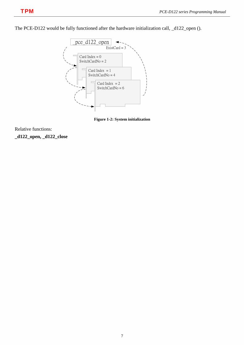
TPM PCE-D122 series Programming Manual The PCE-D122 would be fully functioned after the hardware initialization call, _d122_open ().
Card Index = 0 SwitchCardNo = 2
Card Index = 1 SwitchCardNo = 4
Card Index = 2 SwitchCardNo = 6
_pce_d122_openExistCard = 3
Figure 1-2: System initialization
Relative functions: _d122_open, _d122_close
7
TPM PCE-D122 series Programming Manual
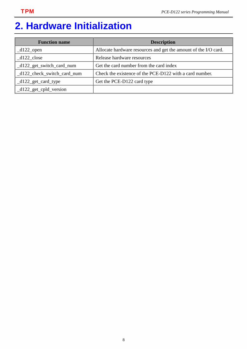
2. Hardware Initialization Function name Description
_d122_open Allocate hardware resources and get the amount of the I/O card. _d122_close Release hardware resources _d122_get_switch_card_num Get the card number from the card index _d122_check_switch_card_num Check the existence of the PCE-D122 with a card number. _d122_get_card_type Get the PCE-D122 card type _d122_get_cpld_version
8

TPM PCE-D122 series Programming Manual
2.1. _d122_open
Description Allocate hardware resources and get the amount of the I/O card. Syntax I16 _d122_open (U16 *existcards) Argument Name Type Description existcards U16 * Get master card count in your PC Status Return
Function Name Description ERR_NoError The function finished execution successfully. Other Please reference to the Appendix error table.
9

TPM PCE-D122 series Programming Manual
2.2. _d122_close
Description Release hardware resources Syntax: I16 _d122_close () Argument N/A Status Return
Function Name Description ERR_NoError The function finished execution successfully. Other Please reference to the Appendix error table.
10
TPM PCE-D122 series Programming Manual
2.3. _d122_get_switch_card_num
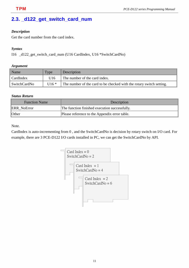
Description Get the card number from the card index. Syntax I16 _d122_get_switch_card_num (U16 CardIndex, U16 *SwitchCardNo) Argument Name Type Description CardIndex U16 The number of the card index. SwitchCardNo U16 * The number of the card to be checked with the rotary switch setting. Status Return
Function Name Description ERR_NoError The function finished execution successfully. Other Please reference to the Appendix error table. Note. CardIndex is auto-incrementing from 0 , and the SwitchCardNo is decision by rotary switch on I/O card. For example, there are 3 PCE-D122 I/O cards installed in PC, we can get the SwitchCardNo by API.
Card Index = 0 SwitchCardNo = 2
Card Index = 1 SwitchCardNo = 4
Card Index = 2 SwitchCardNo = 6
11

TPM PCE-D122 series Programming Manual
2.4. _d122_check_switch_card_num
Description Check the existence of the PCE-D122 with a card number. Syntax I16 _d122_check_switch_card_num (U16 SwitchCardNo, U8 *IsExist) Argument Name Type Description SwitchCardNo U16 The number of the card to be checked with the rotary switch setting. IsExist U8 * Equal to 1 if the card exists, 0 if the card does not exist. Status Return
Function Name Description ERR_NoError The function finished execution successfully. Other Please reference to the Appendix error table.
12

TPM PCE-D122 series Programming Manual
2.5. _d122_get_card_type
Description Get the PCE-D122 card type. Syntax I16 _d122_get_card_type (U16 SwitchCardNo, U8 *CardType) Argument Name Type Description SwitchCardNo U16 The rotary switch set number of the PCE-D122.
CardType U8 *
Card Type Value Meaning
0 CARD_UNKNOWN 1 CARD_PCE_D122 2 CARD_PCE_D132 3 CARD_PCE_D150 4 CARD_PCE_D105
Status Return
Function Name Description ERR_NoError The function finished execution successfully. Other Please reference to the Appendix error table.
13

TPM PCE-D122 series Programming Manual
2.6. _d122_get_cpld_version
Description Get the software version of the CPLD. Syntax I16 _d122_get_cpld_version (U16 SwitchCardNo, U16 *CpldVer) Argument Name Type Description SwitchCardNo U16 The rotary switch set number of the PCE-D122. CpldVer U8 * Returns the current CPLD version. Status Return
Function Name Description ERR_NoError The function finished execution successfully. Other Please reference to the Appendix error table.
14

TPM PCE-D122 series Programming Manual
3. Digital Input / Output Functions Function name Description
_d122_read_input Get input status from all input channels. _d122_read_output Get input status from all output channels. _d122_write_output Generate output signal to all output channels. _d122_read_input_bit Get input status from specified BitNo input channel. _d122_read_output_bit Get input status from specified BitNo output channel. _d122_write_output_bit Generate output signal to specified BitNo output channel. _d122_toggle_output_bit Toggle specified BitNo output channel signal. _d122_read_port Get input status from specified input or output port. _d122_write_port Generate output signal to specified output port.
15
TPM PCE-D122 series Programming Manual
3.1. _d122_read_input
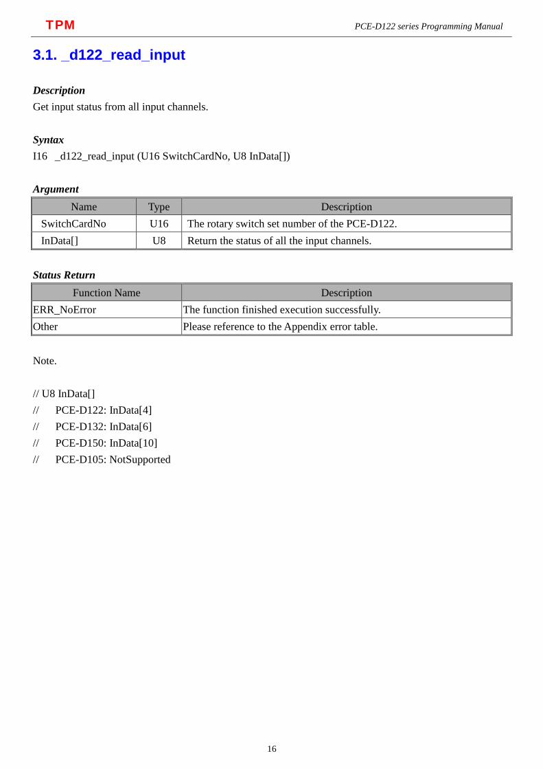
Description Get input status from all input channels. Syntax I16 _d122_read_input (U16 SwitchCardNo, U8 InData[]) Argument
Name Type Description SwitchCardNo U16 The rotary switch set number of the PCE-D122. InData[] U8 Return the status of all the input channels.
Status Return
Function Name Description ERR_NoError The function finished execution successfully. Other Please reference to the Appendix error table. Note. // U8 InData[] // PCE-D122: InData[4] // PCE-D132: InData[6] // PCE-D150: InData[10] // PCE-D105: NotSupported
16
TPM PCE-D122 series Programming Manual
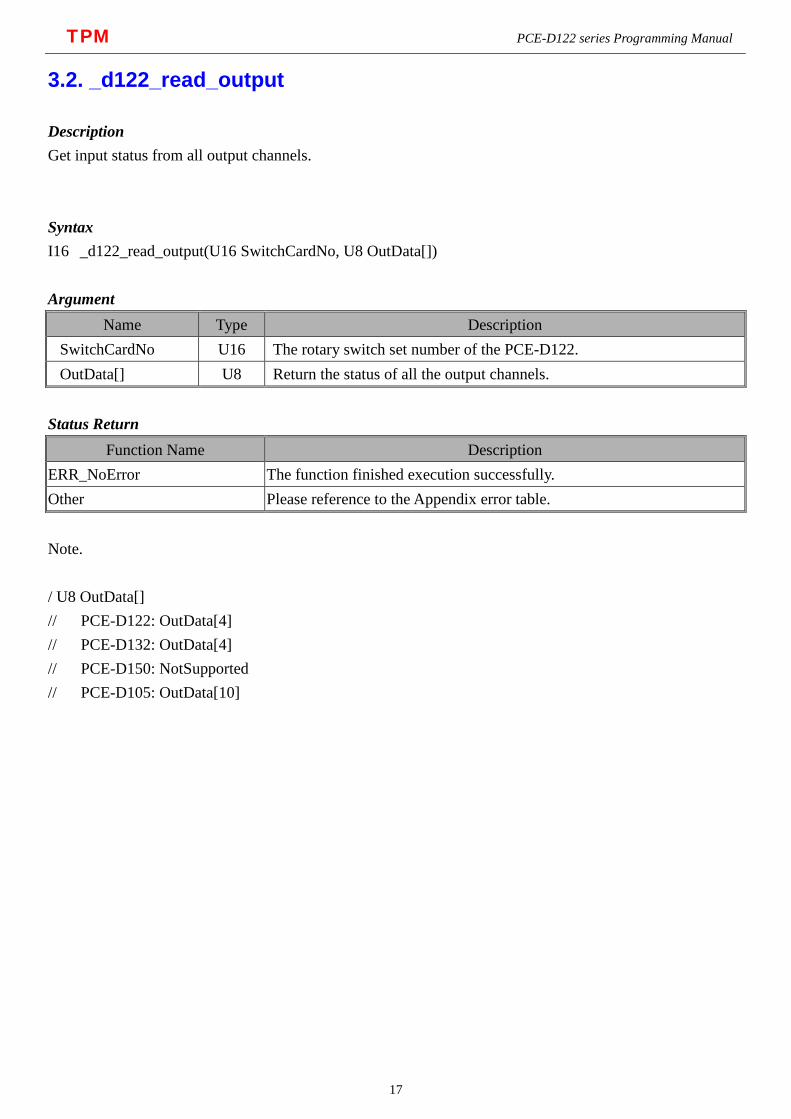
3.2. _d122_read_output
Description Get input status from all output channels. Syntax I16 _d122_read_output(U16 SwitchCardNo, U8 OutData[]) Argument
Name Type Description SwitchCardNo U16 The rotary switch set number of the PCE-D122. OutData[] U8 Return the status of all the output channels.
Status Return
Function Name Description ERR_NoError The function finished execution successfully. Other Please reference to the Appendix error table. Note. / U8 OutData[] // PCE-D122: OutData[4] // PCE-D132: OutData[4] // PCE-D150: NotSupported // PCE-D105: OutData[10]
17
TPM PCE-D122 series Programming Manual
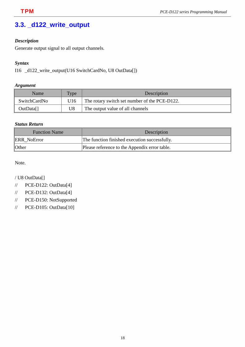
3.3. _d122_write_output
Description Generate output signal to all output channels. Syntax I16 _d122_write_output(U16 SwitchCardNo, U8 OutData[]) Argument
Name Type Description SwitchCardNo U16 The rotary switch set number of the PCE-D122. OutData[] U8 The output value of all channels
Status Return
Function Name Description ERR_NoError The function finished execution successfully. Other Please reference to the Appendix error table. Note. / U8 OutData[] // PCE-D122: OutData[4] // PCE-D132: OutData[4] // PCE-D150: NotSupported // PCE-D105: OutData[10]
18

TPM PCE-D122 series Programming Manual
3.4. _d122_read_input_bit
Description Get input status from specified BitNo input channel. Syntax I16 _d122_read_input_bit(U16 SwitchCardNo, U8 InBitNo, U8 *OnOff) Argument
Name Type Description SwitchCardNo U16 The rotary switch set number of the PCE-D122. InBitNo U8 BitNo of channel
OnOff U8* On_Off = 1, Status of BitNo is ON On_Off = 0, Status of BitNo is OFF
Status Return
Function Name Description ERR_NoError The function finished execution successfully. Other Please reference to the Appendix error table. Note. // U8 InBitNo // PCE-D122: 0 ~ 31 // PCE-D132: 0 ~ 47 // PCE-D150: 0 ~ 79 // PCE-D105: NotSupported
19

TPM PCE-D122 series Programming Manual
3.5. _d122_read_output_bit
Description Get input status from specified BitNo output channel. Syntax I16 _d122_read_output_bit(U16 SwitchCardNo, U8 OutBitNo, U8 *OnOff) Argument
Name Type Description SwitchCardNo U16 The rotary switch set number of the PCE-D122. OutBitNo U8 BitNo of channel
OnOff U8* On_Off = 1, Status of BitNo is ON On_Off = 0, Status of BitNo is OFF
Status Return
Function Name Description ERR_NoError The function finished execution successfully. Other Please reference to the Appendix error table. Note. // U8 OutBitNo // PCE-D122: 0 ~ 31 // PCE-D132: 0 ~ 31 // PCE-D150: NotSupported // PCE-D105: 0 ~ 79
20

TPM PCE-D122 series Programming Manual
3.6. _d122_write_output_bit
Description Generate output signal to specified BitNo output channel. Syntax I16 _d122_write_output_bit(U16 SwitchCardNo, U8 BitNo, U8 OnOff) Argument
Name Type Description SwitchCardNo U16 The rotary switch set number of the PCE-D122. OutBitNo U8 BitNo of channel
OnOff U8 On_Off = 1, Status of BitNo is ON On_Off = 0, Status of BitNo is OFF
Status Return
Function Name Description ERR_NoError The function finished execution successfully. Other Please reference to the Appendix error table. Note. // U8 OutBitNo // PCE-D122: 0 ~ 31 // PCE-D132: 0 ~ 31 // PCE-D150: NotSupported // PCE-D105: 0 ~ 79
21
TPM PCE-D122 series Programming Manual
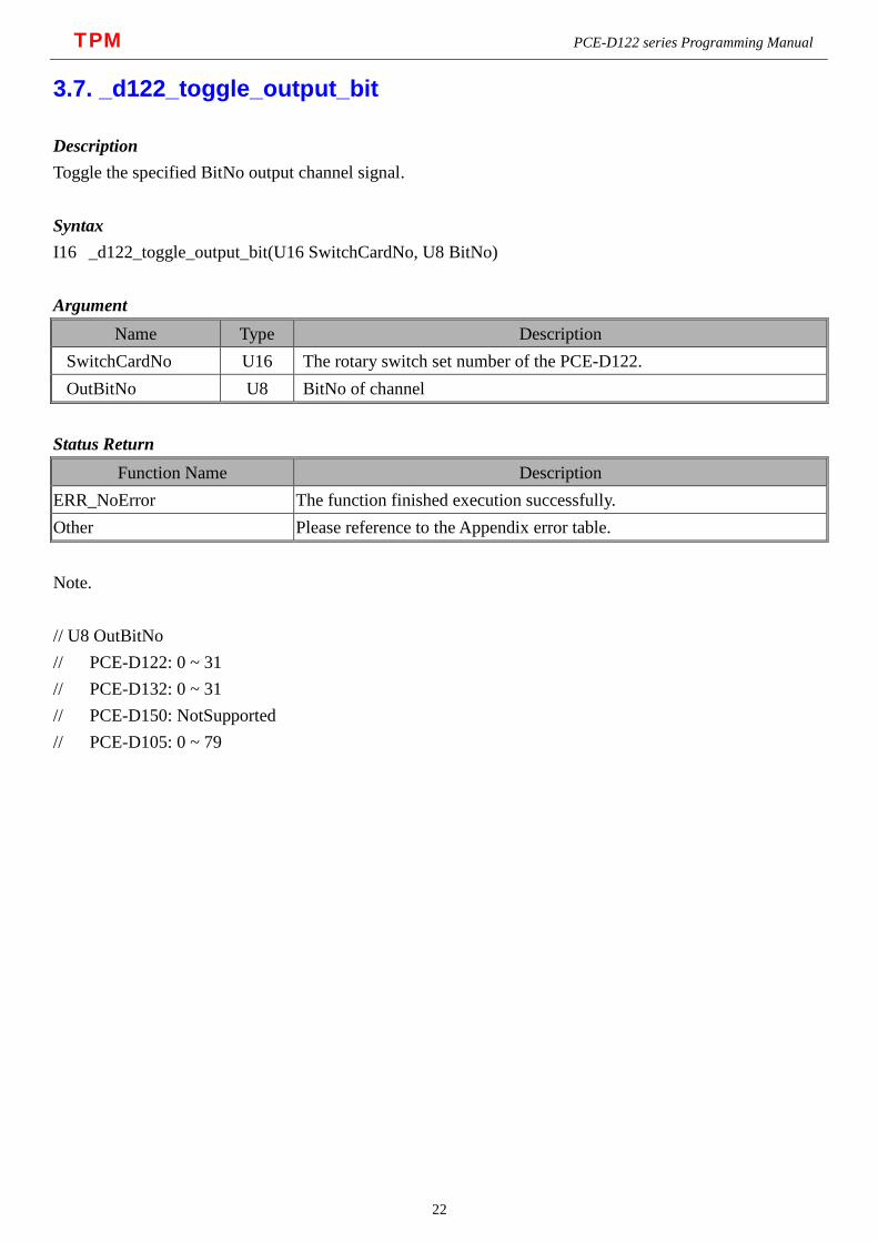
3.7. _d122_toggle_output_bit
Description Toggle the specified BitNo output channel signal. Syntax I16 _d122_toggle_output_bit(U16 SwitchCardNo, U8 BitNo) Argument
Name Type Description SwitchCardNo U16 The rotary switch set number of the PCE-D122. OutBitNo U8 BitNo of channel
Status Return
Function Name Description ERR_NoError The function finished execution successfully. Other Please reference to the Appendix error table. Note. // U8 OutBitNo // PCE-D122: 0 ~ 31 // PCE-D132: 0 ~ 31 // PCE-D150: NotSupported // PCE-D105: 0 ~ 79
22

TPM PCE-D122 series Programming Manual
3.8. _d122_read_port
Description Get input status from specified input or output port. Syntax I16 _d122_read_port(U16 SwitchCardNo, U8 PortNo, U8 *Value) Argument
Name Type Description SwitchCardNo U16 The rotary switch set number of the PCE-D122. PortNo U8 Port No 0 ~ 7 Value U8* Return the status of the specified input or output port.
Status Return
Function Name Description ERR_NoError The function finished execution successfully. Other Please reference to the Appendix error table. Note. // U8 PortNo // PCE-D122: 0 ~ 7 // PCE-D132: 0 ~ 9 // PCE-D150: 0 ~ 9 // PCE-D105: 0 ~ 9 // // D122 D132 D150 D105
// Port0: DI[ 0.. 7] DI[ 0.. 7] DI[ 0.. 7] DO[ 0.. 7]
// Port1: DI[ 8..15] DI[ 8..15] DI[ 8..15] DO[ 8..15]
// Port2: DI[16..23] DI[16..23] DI[16..23] DO[16..23]
// Port3: DI[24..31] DI[24..31] DI[24..31] DO[24..31]
// Port4: DO[ 0.. 7] DI[32..39] DI[32..39] DO[32..39]
// Port5: DO[ 8..15] DI[40..47] DI[40..47] DO[40..47]
// Port6: DO[16..23] DO[ 0.. 7] DI[48..55] DO[48..55]
// Port7: DO[24..31] DO[ 8..15] DI[56..63] DO[56..63]
// Port8: DO[16..23] DI[64..71] DO[64..71]
// Port9: DO[24..31] DI[72..79] DI[72..79]
23

TPM PCE-D122 series Programming Manual
3.9. _d122_write_port
Description Generate output signal to specified output port. Syntax I16 _d122_write_port(U16 SwitchCardNo, U8 PortNo, U8 Value) Argument
Name Type Description SwitchCardNo U16 The rotary switch set number of the PCE-D122. PortNo U8 Port No 4 ~ 7 Value U8 Set the status of the specified output port.
Status Return
Function Name Description ERR_NoError The function finished execution successfully. Other Please reference to the Appendix error table. Note. // U8 PortNo // PCE-D122: 0 ~ 7 // PCE-D132: 0 ~ 9 // PCE-D150: 0 ~ 9 // PCE-D105: 0 ~ 9 // // D122 D132 D150 D105
// Port0: DI[ 0.. 7] DI[ 0.. 7] DI[ 0.. 7] DO[ 0.. 7]
// Port1: DI[ 8..15] DI[ 8..15] DI[ 8..15] DO[ 8..15]
// Port2: DI[16..23] DI[16..23] DI[16..23] DO[16..23]
// Port3: DI[24..31] DI[24..31] DI[24..31] DO[24..31]
// Port4: DO[ 0.. 7] DI[32..39] DI[32..39] DO[32..39]
// Port5: DO[ 8..15] DI[40..47] DI[40..47] DO[40..47]
// Port6: DO[16..23] DO[ 0.. 7] DI[48..55] DO[48..55]
// Port7: DO[24..31] DO[ 8..15] DI[56..63] DO[56..63]
// Port8: DO[16..23] DI[64..71] DO[64..71]
// Port9: DO[24..31] DI[72..79] DI[72..79]
24

TPM PCE-D122 series Programming Manual
4. Appendix A – Error Codes ERR_NoError 0 ERR_InvalidSwitchCardNumber -1
ERR_SwitchCardNumberRepeated -2
ERR_MapMemoryFailed -3
ERR_CardNotExist -4
ERR_InvalidBoardID -5
ERR_InvalidParameter1 -6
ERR_InvalidParameter2 -7
ERR_InvalidParameter3 -8
ERR_InvalidParameter4 -9
ERR_InvalidParameter5 -10
ERR_InvalidParameter6 -11
ERR_InvalidParameter7 -12
ERR_InvalidParameter8 -13
ERR_InvalidParameter9 -14
D122ERR_NotSupported -15
25