pcm-11 application module operator’s manual · it is important that you become familiar with...
TRANSCRIPT

PCM-11 Application ModuleOperator’s Manual


PCM-11 Application ModuleOperator’s Manual
Information furnished by EMERSON EMC is believed to be accurate andreliable. However, no responsibility is assumed by EMERSON EMC for its use.EMERSON EMC reserves the right to change the design or operation of theequipment described herein and any associated motion products withoutnotice. EMERSON EMC also assumes no responsibility for any errors thatmay appear in this document. Information in document is subject to changewithout notice.
P/N 400283-00 Rev.: A2Date: Sept. 1, 1995
i

Customer Services:EMERSON EMC offers a wide range of services to support our customer’sneeds. Listed below are some examples of these services.
Service Support (612) 474-8833Emerson Electronic Motion Control’s products are backed by a team ofprofessionals who will service your installation wherever it may be. Ourcustomer service center in Minneapolis, Minnesota is ready to help you solvethose occasional problems over the telephone. Our customer service center isavailable 24 hours a day for emergency service to help speed any problemsolving. Also, all hardware replacement parts, should they ever be needed, areavailable through our customer service organization. Need on-site help?Emerson EMC provides on-site service, in most cases, the next day. Just callEmerson EMC’s customer service center when on-site service or maintenanceis required.
Training Services (612) 474-1116Emerson EMC maintains a highly trained staff of instructors to familiarizecustomers with Emerson EMC’s products and their applications. A number ofcourses are offered, many of which can be taught in your plant upon request.
Application Engineering (612) 474-1116 An experienced staff of factory application engineers provide completecustomer support for tough or complex applications. Our engineers offer you abroad base of experience and knowledge of electronic motion controlapplications.
Bulletin Board System (612) 474-8835Emerson EMC maintains a BBS which provides you access to softwareupdates, and technical information and services.
Communications protocol: 300-14,400 baud, N, 8, 1
FAX (612) 474-8711
ii
Table of ContentsCustomer Services:............................................................................... iiOverview-PCM-11 Motion Program Controller.................................. 1Navigating PCX Software.................................................................... 3Installing Your PCM-11....................................................................... 5
Inputs ................................................................................................ 5Outputs ............................................................................................. 5
PCM-11 Features ................................................................................. 7Axis ID Description........................................................................... 7
Axis ID Setup................................................................................. 7Global External Input Time Limit................................................... 8
Global External Input Time Limit Setup..................................... 8Internal Input and Output Lines..................................................... 9
Internal Input/Output Setup ...................................................... 11Programmable Limit Switches (PLS) ............................................ 12
PLS Setup .................................................................................... 13User Registers................................................................................. 14
User Registers Setup................................................................... 15Equations ........................................................................................ 16
Equation Setup ............................................................................ 17User Messages ................................................................................ 18
Messages Setup ........................................................................... 18Building Your Program...................................................................... 19
Programming Functions ................................................................. 21C Compound Next Index ................................................................ 21D Dwell Time ................................................................................. 23E End Program ............................................................................... 23F Set Maximum Following Error .................................................. 24H Call Home.................................................................................... 24I Call Index...................................................................................... 24O Set Outputs ................................................................................ 24P Call Program................................................................................ 25Q Set Maximum Torque Output ................................................... 25J, W Jump/Wait .............................................................................. 26
Using Jump/Wait Statements in a Program.............................. 26Jump Commands ......................................................................... 27Wait For Input Commands ........................................................ 28
/ + - * ^ Math Operators ............................................................. 29Using Math Operators in a Program.......................................... 29
= Load Value ................................................................................... 30Using Load Value in a Program ................................................. 30
B Conditional Branches.................................................................. 31Using Conditional Branches in a Program ................................ 32
DC Drive Command........................................................................ 32Using Drive Commands in a Program ....................................... 33
I, PJ Program Index, Program Jog ................................................ 33LB Labels ........................................................................................ 35
Using a Label in a Program ........................................................ 35
Table of Contents
iii

M Math Equation............................................................................ 35Using Math Equations in a Program ...................................... 35
RT Real-Time Clock........................................................................ 36ST Stop Motion ............................................................................... 36
Using the Stop Motion Command in a Program .................... 36WI Write Index, WJ Write Jog....................................................... 37
Using WJ Write Jog in a Program .......................................... 37Using WI Write Index in a Program ....................................... 37
Transmit Data (X)........................................................................... 38Suspend/Resume Functions............................................................... 39
Suspend Screen Parameters .......................................................... 39Run Program On Suspend ...................................................... 40Program Number...................................................................... 40Automatically Clear After Program ........................................ 40Automatically Resume ............................................................. 40Automatically Return After Resume....................................... 40Automatically Suspend Upon Fault ........................................ 41
PCM-11 Input/Output Functions ..................................................... 43PCM-11 Input Functions ................................................................ 43PCM-11 Output Functions ............................................................. 46
Appendix A - List of Figures.............................................................A-1
PCM-11 Application Module Operator's Manual
iv

Overview-PCM-11 Motion ProgramController
This manual provides setup and programming information for the PCM-11Motion Program Controller. The PCM-11 Motion Program Controller is anApplication Module that attaches to the front of any EMERSON EMC FXPostioning Servo Drive and adds the ability to combine indexes, dwell times,and other functions to form a complete motion sequence, or “program”. Thefeatures provided by the PCM-11 Motion Program Controller include:
• 256 indexes (as opposed to 32 indexes in the base FX drive)
• 99 programs and a maximum of 1,024 program steps
• Dwell times between any two program steps (not just between indexes asin the basic FX drive)
• Wait to continue function that halts program flow until selectedinternal and/or external input lines become active
• Jump function to other parts of the program depending on the conditionof the selected internal and/or external input lines
• Programmable internal and external output lines that becomeactive depending on program instructions
• Programmable Limit Switch option for programmable output lines
• Change maximum following error function during a program
• Change maximum torque function during a program
• Suspend/Resume Programfunction that records existing program dataat time of interruption and permits later completion of the interruptedprogram.
• Compound Index function that changes motor velocity at completion ofcompounded index distance to velocity of next index without stopping
• Logic, math, and branching functions that control program flowbased on current conditions
• and many more.
The firmware revision on a PCM-11 module necessary for all of the programmingfeatures in this manual is A5 or higher. You can find the revision number of yourmodule by looking at the serial number sticker located on the side of the module.The revision number is found in the “REV” field.
The PCX version that is shipped with this Application Module will work withprevious revisions of EMERSON EMC Application Modules and FX Drives.However, some of the features described in this manual will not be availablefor use with earlier equipment and will not appear on screen when on-linewith PCX6.05.
Overview-PCM-11 Motion Program Controller
1

It is important that you become familiar with “PCX Software Setup andOperation” in the FX Drive Operator’s Installation and Programming Manual(P/N 400282-00). It provides the basic information needed to set up andprogram the FX drive using PCX software (ver. 6.5 or above).
The FX Drive’s firmware is disabled whenever an Application Module such asthe PCM-11 Motion Program Controller is attached. Therefore, the FX Drive’sfirmware can be any version since the programming features reside in theApplication Module’s non-volatile memory.
The PCM-11 stores FX Drive setup parameters within the PCM-11 module.This allows you to transfer the PCM-11 to another FX Amplifier withoutlosing setup parameters.
PCM-11 Application Module Operator's Manual
2

Navigating PCX SoftwareAdding a PCM-11 Motion Program Controller to an FX Drive gives you severaladditional features in PCX. The hierarchy menu diagrams in Figures 1 and 2show the additional features in the shaded blocks.
Figure 1PCX Hierarchy Diagram 1
Navigating PCX Software
3

Figure 2PCX Hierarchy Diagram 2
PCM-11 Application Module Operator's Manual
4
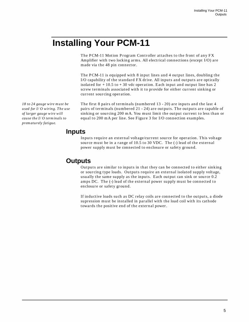
Installing Your PCM-11The PCM-11 Motion Program Controller attaches to the front of any FXAmplifier with two locking arms. All electrical connections (except I/O) aremade via the 48 pin connector.
The PCM-11 is equipped with 8 input lines and 4 output lines, doubling theI/O capability of the standard FX drive. All inputs and outputs are opticallyisolated for +10.5 to +30 vdc operation. Each input and output line has 2screw terminals associated with it to provide for either current sinking orcurrent sourcing operation.
18 to 24 gauge wire must beused for I/O wiring. The useof larger gauge wire willcause the I/O terminals toprematurely fatigue.
The first 8 pairs of terminals (numbered 13 - 20) are inputs and the last 4pairs of terminals (numbered 21 - 24) are outputs. The outputs are capable ofsinking or sourcing 200 mA. You must limit the output current to less than orequal to 200 mA per line. See Figure 3 for I/O connection examples.
InputsInputs require an external voltage/current source for operation. This voltagesource must be in a range of 10.5 to 30 VDC. The (-) lead of the externalpower supply must be connected to enclosure or safety ground.
Outputs Outputs are similar to inputs in that they can be connected to either sinkingor sourcing type loads. Outputs require an external isolated supply voltage,usually the same supply as the inputs. Each output can sink or source 0.2amps DC. The (-) lead of the external power supply must be connected toenclosure or safety ground.
If inductive loads such as DC relay coils are connected to the outputs, a diodesupression must be installed in parallel with the load coil with its cathodetowards the positive end of the external power.
Installing Your PCM-11Outputs
5
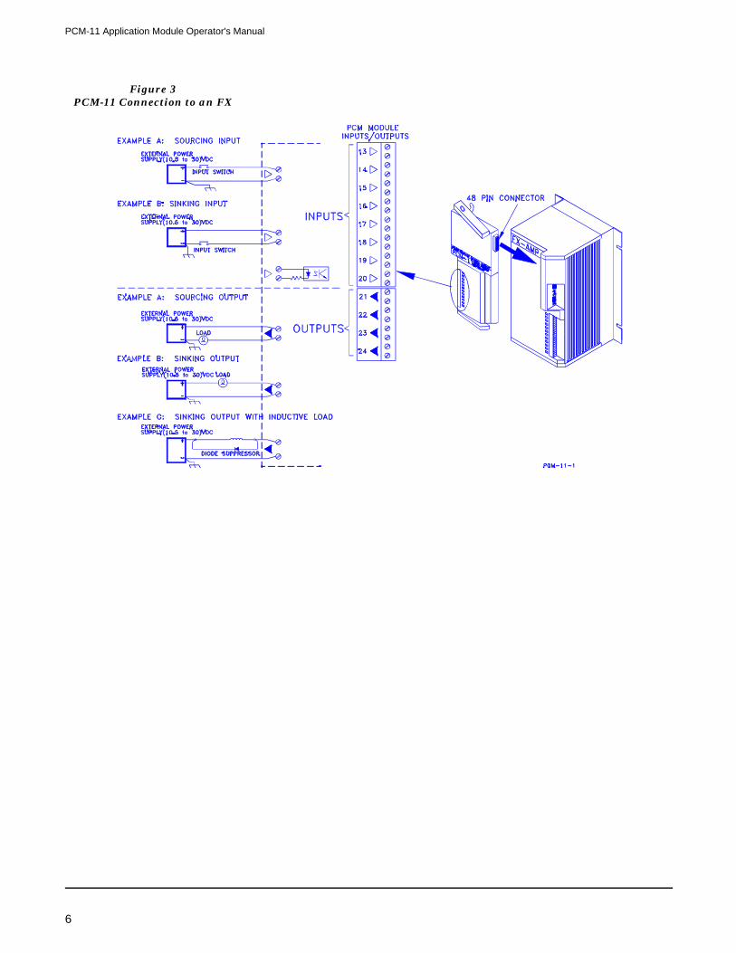
Figure 3PCM-11 Connection to an FX
PCM-11 Application Module Operator's Manual
6

PCM-11 FeaturesEach of the following PCM-11 features must be set up before you can use themin a program. The appropriate menu for each feature can be found under thePCX menu whose title follows the feature. Individual setup information foreach feature is covered in this chapter.
• Axis ID Description (Drive Setup, Drive Configuration, ParametersMenu)
• Global External Input Time Limit (Drive Setup, Drive Configuration,Limits Menu)
• Internal Input Lines (Drive Setup, Drive Configuration, InputFunctions Menu)
• Internal Output Lines (Drive Setup, Drive Configuration, OutputFunctions Menu)
• Programmable Limit Switch Operations (Drive Setup, DriveConfiguration, Programmable Limit Switches Menu)
• User Registers (Drive Setup, Define Motion, Programming, UserRegisters Menu)
• Equations (and Math Operations) (Drive Setup, Define Motion,Programming, Equations Menu)
• User Messages (Drive Setup, Define Motion, Programming, UserMessages)
Axis ID DescriptionThe following applies to allPCX entries:If you make an entry andpress the up or down arrowkeys instead of the <Enter>key, PCX will ignore yourentry and restore the existingdata to the screen.
This function allows you to enter a unique, 32 character, alphanumericdescription for each axis in your system that will be displayed at the top ofeach PCX screen. The descriptions allow you to quickly identify an axis by it’sfunction in a multi-axis system. The axis description will also be displayed tothe right of the axis ID on the “Select Drive Screen” when more than one FXDrive is communicating with PCX.
Axis ID SetupThe Axis ID Description is entered in Drive Setup, Drive Configuration,Parameters. Move the cursor to the Axis ID Description line in the ParametersMenu and type the description for that axis. After you have typed thedescription, press the <Enter> key to transmit the information to the drive.
Because the Axis ID description is stored in the Application Module’snon-volatile memory, the module will retain its Axis ID Descriptioninformation when moved to another FX Drive.
PCM-11 FeaturesAxis ID Description
7

Global External Input Time LimitAn optional time limit has been added to the Wait for Input Function. Thisnew function will prevent program execution from waiting indefinitely at aWait for Input program statement when a required sensor input is notreceived.
The time limit, entered in seconds, will monitor any instance of Wait for Input, Waitfor Single Input, or Wait for Input Pattern Match and move to the next step in theprogram if an input is not received before the time limit expires. This time limitfunction, if used, times and monitors all external input lines and all programfunctions that use any form of Wait for External Input. The time limit resets aftereach wait statement and applies to all lines in use.
If your application requires that individual input lines have different timelimits, a separate program sub-section can be written to monitor the criticallines with time limits that are specific to that part of the program. (See thedescription of the Real-Time Clock (RT) under Direct Drive Commands of thismanual).
Global External Input Time Limit SetupSelect Drive Configuration, Limits Menu. Move the cursor to the “GlobalExternal Input Time Limit” line and enter the time limit needed in seconds.Minimum time monitored will be .001 seconds; maximum time is2,147,483.647 seconds (or 24.8 days). After making the entry, press the<enter> key.
Figure 4Drive Parameters Screen
PCM-11 Application Module Operator's Manual
8

Internal Input and Output LinesThis feature enables the drive to signal itself without using hardware input oroutput lines. For example; If your application requires the drive to be flaggedthat a particular step has been completed while a program is running, you cansimply assign an internal output to flag an internal input.
There are 16 internal input and 16 internal output lines available, giving youaccess to a total of 32 input (16 hardware and 16 internal) and 24 output (8hardware and 16 internal) lines per FX Drive with a PCM-11. The internalinput lines support Jump and Wait statement conditions. The Jump and Waitinputs can also be overlapped between the hardware lines and the internallines.
For example, if input function #28 (Jumps/Wait Inputs) is assigned tohardware line 17, and 8 input lines are selected, then the Inputs would beassigned to hardware lines 17-20 along with internal input lines I1-I4. Halfwould be assigned to hardware inputs and half would be assigned to internalinputs (see Figure 6 and 7 ).
Figure 5Global External Input
Time Limit Setup
Figure 6Hardware (External) Input
Line Assignments
PCM-11 FeaturesInternal Input and Output Lines
9

Press the F2 key to display the internal input lines.
The maximum number ofPGO lines is 16; themaximum number ofJump/Wait Input lines is 8.
Similarly, the internal output lines support programmable outputs (PGOs).The PGOs can be overlapped between the hardware output lines and theinternal output lines. For example, if output #12 (PGOs) is assigned tohardware line 9, and sixteen output lines are selected, then the PGOs wouldbe assigned to hardware output lines 9,10,11, and 12, along with internaloutput lines 1 through 12.
Press the F2 key to display the internal output lines.
Figure 7Software (Internal) Input Line
Assignments
Figure 8Internal Output Line
Assignments
PCM-11 Application Module Operator's Manual
10

The “internal” lines are assigned just as normal hardware lines with thefollowing differences:
Internal Inputs are designated by I1 through I16 (i.e., letter “I”, not numeral1).
Internal Outputs are designated by O1 through O16 (i.e., letter “O”, notnumeral Ø).
All output lines, both hardware lines and internal lines, can be assigned toconnect to input lines on the Input Function Screen. This allows you to attacha hardware or internal output line directly to an input line (hardware orinternal) to allow outputs to trigger inputs without the need for externalwiring.
If you assign an internal or hardware output line to trigger a hardware inputline, the LED on the FX Drive or PCM-11 associated with that line will notglow when the logic makes the line active. Only externally supplied currentdraw will cause the LED to light up.
Internal Input/Output SetupTo equip a hardware or internal output line that internally enables either ahardware or internal input line, select Drive Setup, Drive Configuration,Input Functions and move the cursor to the end of the menu to the sectionlabeled “Output Connections”.
If you want to assign a hardware or internal output line to an input line(either hardware or internal), move the cursor to the output line you wish touse and enter the number of the input line (1 - 8, 13 - 20 or I1 - I16) that youwant the output line to connect to. The input line that you designate will beactivated any time the output line is turned on regardless of the function thatturns on the output line.
Figure 9Internal Output Line
Assignments
PCM-11 FeaturesInternal Input and Output Lines
11

In Figure 10, hardware output line #9 is internally connected to input line#1 and internal output line #O1 is connected to hardware input line #2.On the left side of the screen under “Input Assignments” the output numberis in parentheses to the right of the input it has been assigned to.
You can monitor function assignments to Internal Input and Output Lines bypressing the <F2> key. A second line listing will be displayed on the left sideof the screen, showing all the assignments for the internal lines. If an input oroutput line, either hardware or internal, has so many functions assigned to itthat the listing scrolls off the PCX screen in the upper left corner, use the<ALT> key plus the -> or <- arrow keys to scroll through all of theassignments.
Programmable Limit Switches (PLS)Programmable Limit Switch (PLS) patterns can be updated at 16 specificmotor positions using the existing Programmable Output Lines (PGOs) anduser units to define motor position. The pattern you set is the way the lineswill look after the motor enters that position range.
A PLS pattern consists of a specific combination of On, Off, and Don’tChange line conditions of the programmable output lines. Sixteen differentpatterns may be entered to occur at the intervals you specify. Patterns can beupdated at 16 different motor positions. There are 38 (6561) possible patternsavailable. You may use a maximum of 16 output lines.
The default mask for programmable limit switch operation (all X’s, meaningDon’t Change the existing line condition) disables the PLS function. As theX’s are changed to 1’s or Ø’s, the associated PLS pattern will become active atthat motor position.
Figure 10Output Connection to an
Input Line
PCM-11 Application Module Operator's Manual
12

Motor position is referenced by user units. Once PLS patterns are set up themotion range of the motor is divided into sections. When the specified sectionis reached (from either direction), the output pattern associated with thatrange will activate the assigned output lines and program execution willcontinue. Lines set to “X” will remain unchanged. The PLS pattern remains inthat state until the next range is reached by virtue of the changing motorposition. However, you may set a time delay to turn off a particular pattern.
When a non-zero pulse width is entered for a given PLS pattern, the patternwill remain in that state for that amount of time. After the pulse width timehas expired, the lines are set to all Ø’s meaning “OFF”. Lines masked with“X” remain unchanged.
If another PLS range is reached before the pulse width time expires, the newpattern is set immediately and the time delay is ignored.
The PLS functions remain active once they are enabled. There is no way toremotely enable or disable this function after patterns have been enteredby PCX. The only way to disable the PLS function is through the InitializeMemory option: PLS Data.
PLS SetupBefore setting up a PLS pattern you will need to assign one or more outputlines (either hardware or internal) as programmable outputs. This is done inthe Drive Setup, Drive Configuration, Output Functions menu. Select OutputFunction 12, Programmable Outputs. After you enter the line number of thehardware or internal Output Line that is the first of your programmableoutput lines, enter the number (quantity) of lines you want to use (maximum16 lines) and press <Enter>.
To set a Programmable Limit Switch Pattern, select Drive Setup, DriveConfiguration, Programmable Limit Switches. The screen you see will looklike Figure 11.
Figure 11Programmable Limit Switches
PCM-11 FeaturesProgrammable Limit Switches (PLS)
13

Your cursor will highlight the starting point of the first position range(typically zero when starting out). Enter the first range starting positionincluding decimal point and then press the <Enter> key. The cursor willmove to the Pattern Area and highlight the first column.
This column represents the first Programmable Output line that you assigned(that line number will be shown above next to the word “Pattern”). At thispoint, enter a 1 to turn a line On, a Ø to turn a line Off, or an X for Don’tChange this line.
Do not press the <Enter> key at this point. You will notice that after everyentry the cursor moves to the next column. Wait to press the <Enter> keyuntil you are finished entering or correcting the desired pattern. When youhave completed the pattern for this range, press the <Enter> key and thecursor will move to the Pulse Width area.
If you enter a Pulse Width (or time delay) in seconds in this field, the pattern youhave just entered will come on when the motor enters this range from eitherdirection and stay on for the amount of time you enter. When the time expires, alllines marked with a “1” will be turned off. Lines with an “X” will not be changed.
However, if the motor is moving through the range faster than the PulseWidth you have selected, the next range pattern will be set on the output linesas soon as that range is entered. Only lines marked with “X” in the next rangewill not be changed.
After you enter the pulse width (or Ø for the pattern to remain until the motorenters the next range), press <Enter>. The cursor will move to the next PLSstarting point.
In the example screen in Figure 11, assuming a 25 inch linear range is active,the PLS pattern will show all lines off when the motor position goes below2.000 in., including positions less than zero. The pattern will remain as inposition 4, when the motor position is over 25.000 inches.
If PLS positions are enteredsuch that the sections are outof sequential order, PCXimmediately sorts thepositions in ascendingnumerical order after youenter a position and updatesthe display automatically.
Remember that the pattern will change according to 1) the position the motorenters, and 2) the direction that position is approached from. If the motormoves from 3.000 inches to 1.000 inches, the pattern will go from four linesON, four lines OFF to four lines OFF, four lines ON as the position becomesless than 2.000 inches.
User RegistersUser Registers act as “workspaces” for the storage of data. Examples of storeddata include:
• FX drive variables that are used in math equations.
• Values to be used in conditional branches in programs.
• Flags or counters that act as progress monitors in programs.
PCM-11 Application Module Operator's Manual
14

For example: The system you are programming may need to monitor thenumber of times a particular index has been executed. When the number ofindex executions exceeds that value (we will use 20 for this example), then alarger value needs to be assigned to the index distance. (Assume the axis ispicking up objects from a stack and the stack height is getting progressivelylower). User Register URØØ is given the label “FLAG1”, along with a defaultvalue of Ø, and User Register URØ2 is given the label “LENGTH1”, alongwith a default value of 10.000 in.
The program is then set up to increment User Register “FLAG1” by a value of1 each time the index is run. After each index, the program compares the valueof “FLAG1” against the constant value of 20. When “FLAG1” exceeds 20, UserRegister “LENGTH1” is made equal to the sum of “LENGTH1” + 2.000 in.(using the WI Write Index Parameter program step discussed later). Then“FLAG1” is reset to Ø, and the program continues. As the program continuesto run, each time “FLAG1” exceeds 20, User Register “LENGTH1” willincreased by 2.000 in.
User Registers SetupTo assign default values and descriptive names to user registers, select DriveSetup, Define Motion, Programming, User Registers. You can assign usernames of up to sixteen (16) characters to each of the 64 individual registers,as well as default numeric data values with up to five (5) decimal places.
The column on the left side of the screen displays the user register number(URØØ through UR63). The center column displays the user defined registername (maximum 16 characters), and the column on the right displays the userdefined register default value (up to 5 decimal places).
Once you set the number of decimal places by entering a value, the userregister will retain this number of decimal places until changed by an entryfrom this menu.
Figure 12User Registers Setup Screen
PCM-11 FeaturesUser Registers
15
Register names must startwith an alpha characterrather than a numericcharacter. For example: A1would be accepted; 1A wouldnot.
Any value later stored by action in a program in any particular register willautomatically be stored with that register’s default number of decimal places.Remember, the decimal place accuracy of the register storing the data may notbe the same as the default accuracy of the number BEING stored. If incomingdata has more decimal places than the register was set up for, the excessnumbers are truncated, not rounded off. This may affect the accuracy of someof your calculations.
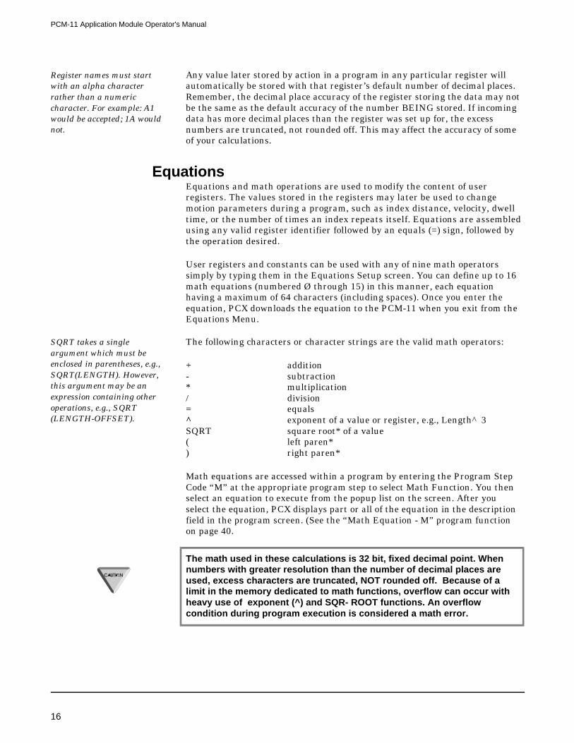
EquationsEquations and math operations are used to modify the content of userregisters. The values stored in the registers may later be used to changemotion parameters during a program, such as index distance, velocity, dwelltime, or the number of times an index repeats itself. Equations are assembledusing any valid register identifier followed by an equals (=) sign, followed bythe operation desired.
User registers and constants can be used with any of nine math operatorssimply by typing them in the Equations Setup screen. You can define up to 16math equations (numbered Ø through 15) in this manner, each equationhaving a maximum of 64 characters (including spaces). Once you enter theequation, PCX downloads the equation to the PCM-11 when you exit from theEquations Menu.
SQRT takes a singleargument which must beenclosed in parentheses, e.g.,SQRT(LENGTH). However,this argument may be anexpression containing otheroperations, e.g., SQRT(LENGTH-OFFSET).
The following characters or character strings are the valid math operators:
+ addition- subtraction* multiplication/ division= equals^ exponent of a value or register, e.g., Length^3SQRT square root* of a value( left paren*) right paren*
Math equations are accessed within a program by entering the Program StepCode “M” at the appropriate program step to select Math Function. You thenselect an equation to execute from the popup list on the screen. After youselect the equation, PCX displays part or all of the equation in the descriptionfield in the program screen. (See the “Math Equation - M” program functionon page 40.
The math used in these calculations is 32 bit, fixed decimal point. Whennumbers with greater resolution than the number of decimal places areused, excess characters are truncated, NOT rounded off. Because of alimit in the memory dedicated to math functions, overflow can occur withheavy use of exponent (^) and SQR- ROOT functions. An overflowcondition during program execution is considered a math error.
PCM-11 Application Module Operator's Manual
16

If a math error occurs while processing a math equation during programexecution, the Program Error Output is turned on but program execution isnot interrupted. You can view the following information on the diagnosticsscreen by pressing the <F10> key:
Lengthy and complexequations (especially thosewith exponents and squareroots) require significantprocessing time, as much as 3msecs. per equation. Be awarethat non-motion steps still gothrough the microprocessorand occupy processing time.
The Program Error Output is cleared by the Clear Program Error Input.
Equation SetupTo enter a math equation for later recall and execution during a program,select Drive Setup, Define Motion, Programming, Equations.
Equations are entered by:
• selecting a User Register for storing the equation results,
• adding an equals (=) sign,
• completing the rest of the equation using other register names and mathoperators.
If you need to recall the names of the registers you have set up, just press theF1 key and a list will appear on the screen. Although the cursor will highlightone of the names, you will need to press the <Esc> key and manually enterthe name of the register you want to work with.
If you enter the name of a register that does not exist, a caution screen will appeartelling you that PCX couldn’t find that register. You have the opportunity at thatpoint of fixing the error before the equation is compiled and execution is attempted.
PCX constantly updates and displays the remaining number of availableprogram steps on the programming screen. PCX 6.5 has the capacity of 1,024program steps for all programs combined. There are a maximum of 100programs (numbered Ø through 99), and a limit of 255 steps in a singleprogram.
Figure 13Equations Screen
PCM-11 FeaturesEquations
17

Equations use some of this space and the amount taken is shown on the top ofthe Equations Screen. The amount per equation is shown next to eachequation.
User MessagesSixteen unique 32 character (including spaces) user messages may be definedand used in PCX programs to assist in monitoring FX Drive performance andprogram progress. Each of these messages may be sent to the FX Drive SerialPort “A” along with corresponding numeric data such as following error,current velocity, current position, etc. This allows you to watch programprogress in PCX terminal mode to see what program portion triggers specificmessages.
Messages SetupSelect Drive Setup, Define Motion, Programming, User Messages. A list of allthe User Messages now appears with User Message URØØ highlighted. Upto 32 characters may be entered for each message. When finished with yourentries, exit the screen by hitting the <Esc>key.
After you have defined your messages you can use them in steps in yourprogram with the “X” command (see “X” - Write to an FX Drive Serial Portfunction in this section). User Messages can be combined with the contents ofUser Registers in a serial string and sent to the FX drive serial port “A”.
Figure 14Messages Screen
PCM-11 Application Module Operator's Manual
18
Building Your ProgramIndexes are described in theFX Drive Operator’sInstallation andProgramming Manual,section “PCX Software Setupand Operation” (P/N400282-00).
Motion Programs are a series of indexes that have been previously set up thatyou combine with other programming steps to create a motion profile. Eachmotion program provides a series of movements in conjunction with othermachine functions. The movements are used to perform a particular machineoperation.
Multiple programs can be created using PCX software and stored in thePCM-11, each designed for a different machine function. The PCM-11 iscapable of storing up to 256 indexes, 100 motion programs (Ø to 99), and amaximum of 1024 program steps in the non-volatile memory.
The number of available programs and average number of steps per programare directly related to each other. The memory is set up such that if yourequire 100 programs (maximum), each program can have an average of 10program steps each. If the number of programs is reduced to a minimum, youcould have as many as 255 steps in a single program.
A motion program is created by entering program functions in the order inwhich they are to be executed. A motion program is made up of function codes,some of which are listed across the bottom of the PCX program screen. To seethe complete list of available codes when you are in the program screen lowerhalf, press the <F1> key. A pop-up screen will display all of the function codes.
As you enter steps in a program, the function codes and function data (indexnumbers, program numbers, dwell times, etc.) are displayed on the programscreen so you can easily follow the program sequence.
You may use any index or program which you have previously created to buildyour program. The example motion program shown in Figure 14 could beaccomplished with one program; however, two programs have been used to showthe use of the Call Program (P) function. In this example, program numbers 1and 2 are used and index numbers 1, 2, 3, 4, and 5 are used.
Building Your ProgramUser Messages
19

Figure 16 and 17 show the program setup screens used to generate the motionprogram in Figure 15 . The program count determines how many times theprogram will be executed. In this example the program count for Program 1 is 10.This means everything within Program 1 will repeat 10 times including Program 2.If the program count is set equal to zero, the program will not execute. If theprogram count is set equal to 65535 or larger, the program will execute indefinitely.
The program function codes determine the actual moves to be executed. Eachfunction will be performed in the sequence that is shown in the programscreen. Once you enter the sequence, you can download the program to the FXdrive by pressing the <Esc> key, or by moving the cursor up to the ProgramNumber position using the arrow keys. The upper left corner of the screen willdisplay a “BUSY” message during the download.
Figure 15Motion Program Example
Figure 16Program Example
PCM-11 Application Module Operator's Manual
20
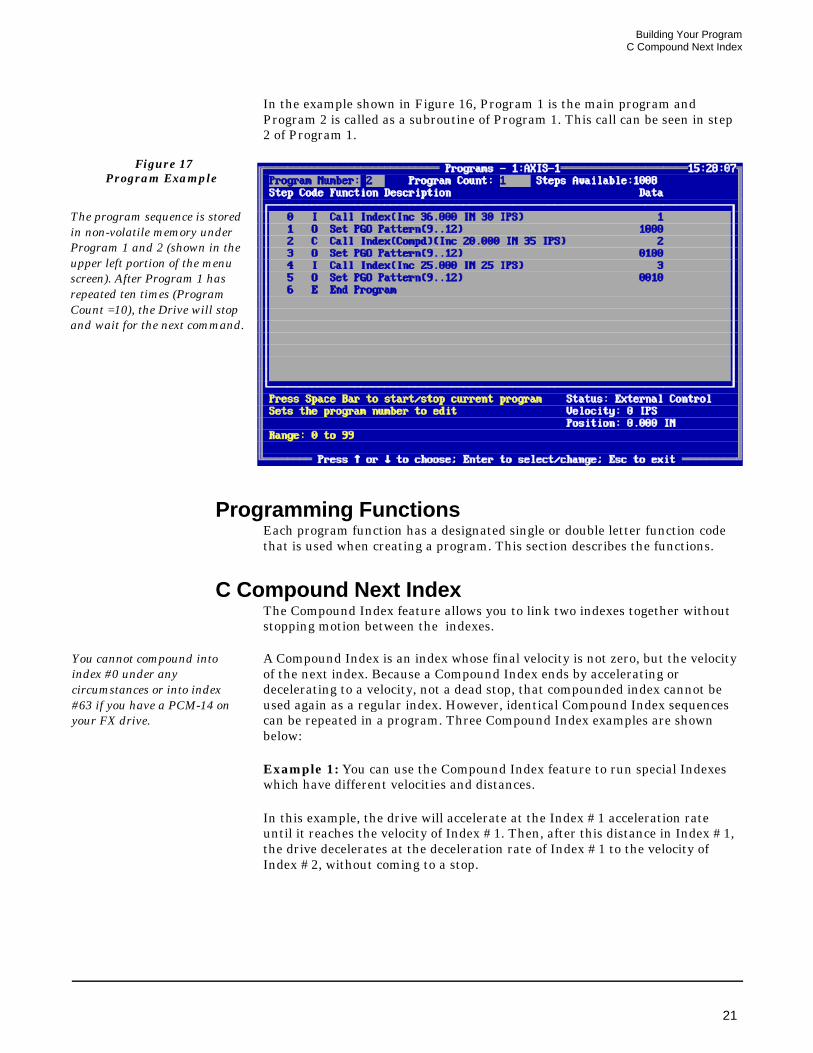
In the example shown in Figure 16, Program 1 is the main program andProgram 2 is called as a subroutine of Program 1. This call can be seen in step2 of Program 1.
Programming FunctionsEach program function has a designated single or double letter function codethat is used when creating a program. This section describes the functions.
C Compound Next IndexThe Compound Index feature allows you to link two indexes together withoutstopping motion between the indexes.
You cannot compound intoindex #0 under anycircumstances or into index#63 if you have a PCM-14 onyour FX drive.
A Compound Index is an index whose final velocity is not zero, but the velocityof the next index. Because a Compound Index ends by accelerating ordecelerating to a velocity, not a dead stop, that compounded index cannot beused again as a regular index. However, identical Compound Index sequencescan be repeated in a program. Three Compound Index examples are shownbelow:
Example 1: You can use the Compound Index feature to run special Indexeswhich have different velocities and distances.
In this example, the drive will accelerate at the Index #1 acceleration rateuntil it reaches the velocity of Index #1. Then, after this distance in Index #1,the drive decelerates at the deceleration rate of Index #1 to the velocity ofIndex #2, without coming to a stop.
Figure 17Program Example
The program sequence is storedin non-volatile memory underProgram 1 and 2 (shown in theupper left portion of the menuscreen). After Program 1 hasrepeated ten times (ProgramCount =10), the Drive will stopand wait for the next command.
Building Your ProgramC Compound Next Index
21

The drive will continue at that velocity until it approaches the programmeddistance of Index 2, then decelerate at the Index #2 deceleration rate to theIndex #3 programmed velocity. It will continue at that velocity until itapproaches the programmed distance of Index #3, at which time it willdecelerate at the Index #3 deceleration rate and stop.
When using multiple compound indexes within the same program, allcompound index directions must be the same. The direction of movementis set by the first of the compound indexes and is not scanned again untilthe next index is initiated that is outside the compound ones.
Example 2: This example is much the same as #1, except in this compoundindex the drive will accelerate instead of decelerate at the end of eachindividual index.
Figure 18Compound Index Example #1
Figure 19Example #2, Compound Index
Motion Profile
PCM-11 Application Module Operator's Manual
22

After completing Index #1, the drive will accelerate at the acceleration rate ofIndex #2 until it reaches the programmed velocity of Index #2. Aftercompleting Index #2 the drive will accelerate to the programmed velocity ofIndex #3 and move at that velocity until it approaches the programmeddistance, at which time it will decelerate at the Index #3 deceleration rate andstop.
Example 3: Use the compound index feature to turn an output on, then offwithout stopping motion. Each index is incremental, has a count of 1, and hasthe same velocity.
D Dwell Time The Dwell Time function allows the program to pause for a number of secondsbetween program functions. Time may be directly entered or recalled from oneof the 64 user registers. Minimum time is 1 ms; maximum time is 65.535seconds.
E End ProgramThis function is used to designate the end of a program. It may be used morethan once when using the Jump commands. The END function is also used toterminate programs prior to the last program step.
Figure 20Compound Index Example #3
Index number 0 may not be usedas a compound index sequence.
Building Your ProgramE End Program
23

F Set Maximum Following Error This function overrides the “Maximum Following Error” which is set up in the“Limits” screen. When the program has completed, Following Error is reset tothe value programmed in the Limits screen. This function is often used with the“Q, Set Maximum Torque” function. A large value entered here prevents thedrive from faulting out during a “Torque” move.
H Call HomeThe Call Home function is used to initiate a previously programmed Home Cycle.There are two Home Cycles that can be called within a program.
I Call IndexThe Call Index function is used to initiate the execution of an index. When thisfunction is used, the index number must also be given. After you enter anindex number in the data field, PCX will display that index’s distance andspeed.
O Set Outputs Entering “O” in a program step will display a sub-menu in the middle of theprogram screen.
1. Set PGO pattern.
Before this function can be used, you must first assign OutputFunction #12 “Programmable Outputs” to one or moreinternal and/or external output lines. This function allows youto change the status of any or all of the programmable outputsyou assigned in the output function screen.
Once selected, the cursor will move to the data field where zerosthat represent the programmable outputs are displayed. Theleftmost zero represents the first programmable output line andthe others follow in numerical sequence. If you enter a one, thatoutput will be forced on.
Figure 21Programmable Output
Options
PCM-11 Application Module Operator's Manual
24

If you enter a zero, that output will be forced off. Theseoutputs will remain in this pattern until they are updated. Ifyou enter an “X” for any line, that line state will not bechanged.
2. Set single output line ON:Turns any output, hardware or internal, on. Output remains in this state.
3. Set single output line OFF:Turns any output, hardware or internal, off. Output remains in this state.
P Call ProgramThe Call Program function is used to initiate a program from within aprogram. You can use the “P” function to call additional programs assub-routines of your original program. This is called “Nesting”. PCX allowsyou to nest up to 30 programs under any one Program Call function beforereturning to the original program.
Use care in constructing programs that create a continuous loop conditionby “Nesting” programs. When nesting programs, your program must returnto the “Master” program somewhere in the loop to prevent programs frombecoming stacked up in memory.
For example: You initiate Program #1, which uses the “P” function to callProgram #2, which uses the “P” to call Program #3, which uses the “P”function to again call Program #2. This continuous loop condition could causethe memory to get stacked up, causing the drive to drop out of the programand return to external mode or register a “Ø” fault on the diagnostic display.
To avoid this condition, make all of your program calls from your originalprogram (Program #1 in this example). Then use the Jump function (J) rightafter the “P” function calling Program #3 to jump back to “P” function callingProgram #2. This will allow the memory (RAM) to clear and the loop tocontinuously run program #2 and #3 from Program #1.
Q Set Maximum Torque Output This function overrides the “Maximum Torque Output” which is set up in the“Limits” screen. When the program has completed, the original value isrestored. If you use a low value for “Q” (less then 100%) you may need to set ahigh value for following error (F). This will avoid faulting the drive if it runsinto a condition requiring more torque than it is allowed to deliver.
Building Your ProgramQ Set Maximum Torque Output
25

J, W Jump/WaitThe Jump and Wait For External Input Functions include unconditionaljumps to another program step, jumps if an input line pattern is matched, or ajump/wait on a single input line being made active, whether that line has beenassigned as an External Input Line or not. The statements “Jump If InputMatch” and “Wait For Input Match” are satisfied if the input line pattern ofactive lines (hardware and/or internal) matches the specified pattern exactly.In addition, a “don’t care” character, “X”, is available to mask off from thepattern any input lines whose condition should be ignored at this point.
Using Jump/Wait Statements in a ProgramWhen the “J” command is entered as a program step, PCX displays the screenshown in Figure 22. The first choice, Jump Always, means exactly that, anunconditional jump to another statement number or label.
The second choice, Jump on Input Pattern (PGI), brings up another windowwith these match selections:
The first and third choices in Figure 23 are alike in that they are asking for anAND condition of the selected Input Lines before jumping to the destinationprogram step. In other words, the Jump will be made if, for example, selectedLines 1 AND 3 AND 4 are ALL on or off, depending on your selection. Anumeral 1 looks for that Input Line to be on or off; the letter X causes thatInput Line condition to be ignored.
The second and fourth choices are alike in that they are asking for an ORcondition of the selected Input Lines before jumping to the destinationprogram step. That is, the Jump will be made if Line 1 OR Line 3 OR Line 4 ison or off, depending on your selection. Again, a numeral 1 looks for that InputLine to be on or off; the letter X causes that Input Line condition to be ignored.
Figure 22Jump Command Options
Figure 23“Jump If” Options
PCM-11 Application Module Operator's Manual
26

The fifth choice, Jump if Input Match, will then ask you for an Input Linepattern to match before Jumping, with numeral 1 representing a Line ON,numeral Ø representing a Line OFF, and X representing a Line whosecondition is ignored by this statement. This choice will Jump programexecution to the specified program step if and only if the exact PATTERN ismatched line for line. If any of these conditions are not met, programexecution proceeds to the next step in the sequence.
Another feature of both jumps and waits is the ability to monitor a singleinput line (hardware or internal) that is independent (or part of) of theexisting jump/wait pattern (i.e. Programmable Input (PGI) Pattern). Thefollowing four jump/wait options are available.
Wait for External Input Functions are very similar, except that programexecution is halted at that spot in the program until the desired Input Linecondition is met. If the condition is not met, program execution proceedsimmediately to the next step.
Jump CommandsTo select this option, enter “J” in the program step. Then select one of threeJump options shown in Figure 25.
The “Jump Always” command is an unconditional jump statement that causesprogram execution to move immediately to the specified program step.
The “Jump on Input Pattern (PGI)” command causes program execution toskip to the designated program step if the specified input lines match thepattern you have selected. If the specified lines do not match that pattern theprogram continues to the next step in the program.
Figure 24Jump/Wait Single Input
Figure 25Jump Command Options
Building Your ProgramJ, W Jump/Wait
27

Before this command can be used in a program, Input Function #28“Wait/Jump Input” must be assigned to one or more hardware or internalinput lines (see “Input Functions” section).
Once the Jump Command has been selected, the cursor will move to the centerof the PCX screen. The zeroes that appear in this field correspond with thenumber of Input Lines selected with Input Function #28. The left-most zerocorresponds to the first input line selected.
You may now choose which lines to monitor during this step by entering a (1)in the field corresponding to the input line you wish to monitor. Any field thathas a zero or an “X” will cause that input line to be ignored during executionof this step.
The “Jump on Single Input Line” command causes program execution to jumpto the designated program step if the specified input line matches thecondition you set in the next screen. This line can be any input line and is notrestricted to those lines assigned to Input function #28, Wait/Jump Inputs. Ifthe specified line does not match the condition (On or Off), the programcontinues to the next step.
Wait For Input Commands Before this command can be used in a program, you must assign InputFunction #28 “Wait/Jump Input” to one or more hardware or internal inputlines (see Input Functions, of this Manual). To use Wait For External Inputwhen editing or writing a program, enter W as a program step. When you haveentered the W, the screen will offer the choices shown in Figure 26.
When the “Wait On Single Input Line” function is selected, the system will holdprogram execution at this step until the designated input line meets the On or Offcondition you select in the next screen. This line can be any hardware or internalinput line and is not restricted to those lines assigned to Input Function #28,Wait/Jump Inputs.
When the “Wait On Input Pattern (PGI)” function is selected, the system willhold program execution at this step until the input pattern you designate inthe pop up menu is satisfied. These lines are restricted to those that you haveassigned as “Wait/Jump” inputs.
Once the Wait Command has been selected and a choice made from the pop-upscreen, the cursor will then move to the center of the PCX screen. Zeroes willappear in this field that correspond to the number of External Lines selectedin the Input Function Screen. The left-most zero will correspond to the firstline selected.
Figure 26Wait for Input Command
Options
PCM-11 Application Module Operator's Manual
28

You now choose which lines to monitor during this step. You make this choiceby entering a “1” in the field corresponding to the line whose state you wish tomonitor. Any field that has a zero or an “X” will cause that line to be ignoredduring execution of this step.
/ + - * ^ Math OperatorsThe equation screen allows you to set up complex equations to be entered,stored, and recalled for execution in a program. You may also perform singlestep math operations on any of the User Registers as a step in a program.
These operations are stored as simple program steps and do not infringe onthe storage capacity for the more complex math equations. Any of thefollowing math operators may be used as program step commands:
/ : divide+ : add- : subtract* : multiply^ : exponent
Using Math Operators in a ProgramTo enter a math operator as a step in a program, move the cursor to thedesired program step and type the math operator you wish to work with (/, +,-, *, ^,) and press <Enter>. PCX will display a window displaying the userregisters. Select the user register in which you want to store the results andpress <Enter>. A second window will pop-up which again displays the userregisters with the added option “Immediate Value”.
If you select Immediate Value you then enter the value that you want to useto modify the register when the program encounters this step.
Figure 27Load Value Setup Options
Building Your Program/ + - * ^ Math Operators
29

Any immediate value between-2,147,483,648 and2,147,483,247 will beaccepted.
For example, to add a count of 1 to user register “Flag1”, the program stepwould appear as:
+ FLAG1 = FLAG1 + 1
If you want to add the contents of register “OFFSET1” to register LENGTH1,the program step would appear as:
+ LENGTH1 = LENGTH1 + OFFSET1
= Load ValueThis function replaces the contents of a User Register with an immediatevalue, the value of the contents of another register, or the value of a driveparameter. The contents of the changed register may now be used as a newdrive parameter, etc.
Using Load Value in a ProgramThis function is selected by entering the equals (=) sign as a program step.When the equals sign is used, a popup window shows four choices:
Load Immediate ValueIf you select this option, PCX will display a pop-up window showing the first16 of the 64 User Data Registers. You can then select the register in which theinformation will be stored. As with other PCX lists, the first letter of thevariable name can be typed for quicker access. Once you select the register,PCX prompts you for the immediate value that you want stored.
Copy User RegisterIf you select this option, PCX prompts you to choose which User Register tochange. When you select the User Register to be changed, PCX then promptsyou for the User Register whose contents are to be copied INTO the first.Remember, the first register selected under this command is the one whosecontents will be set equal to the second register chosen. Values are re-scaled tothe format of the destination (first) register if the decimals are different.
With the drive parametersabove, the value loaded intoany user register will beadjusted to the number ofdecimal places of thedestination register. Eachregister works with thenumber of decimal placesthat were assigned when thedefault data was assigned.
Get Drive Command Data This option enables the program to interrogate the FX Drive at this step in theprogram and store the response in a register. As before, PCX first asks for theregister to use for data storage. Once you specify the register, you may use anytwo-letter FX Drive command query, along with the corresponding commandmodifier. (See FX Drives Serial Commands Manual P/N 400255-00).
Again, ensure that the response to your query will fit properly in the registeryou selected. Data with more than the register’s number of decimal places willbe truncated, not rounded off, so care should be taken to avoid errors that mayresult.
PCM-11 Application Module Operator's Manual
30

Read Drive Parameter DataWhen this option is is selected you will be prompted for the User Register touse for storage. The next four screen clips present a list of possible FX Driveparameters to be read:
B Conditional BranchesConditional branches are set up as steps in a PCX program to establish conditionsthat can change the program execution. This function tests the contents of two userregisters and branches to a step number or label if the condition is true. Otherwise,the next consecutive program step is executed. The contents of the selected userregisters are tested against one of the following conditions:
> greater than< less than= equal to> = greater than or equal to< = less than or equal to
Figure 28Read Drive Parameters
Building Your ProgramB Conditional Branches
31

Using Conditional Branches in a ProgramFigure 29 shows a sample program that uses conditional branch commands insteps 4 and 9.
To insert a Branch condition in your program, move the cursor to the spotwhere the branch is to be made and enter the letter B. Now PCX will displayfour menu windows (one at a time) to set up the conditional branch.
The first window selects the register to be compared. The second window setsthe branching condition. The third window sets the register or immediatevalue, to match against the first register. The fourth window sets the stepnumber or label to branch to if the condition is met.
As mentioned above, if the specified condition is not met, the programproceeds to the next consecutive step.
DC Drive CommandThe DC program step sends drive commands from within the program to theFX Drive. Any serial drive command (except Index Initiate or ProgramInitiate) can be issued from a program. With drive commands, the dataaccompanying the drive command can be either “immediate” (i.e., a constantentered at the program step line), or the current value of a User Register.
This would allow, for example, a change of Maximum Following Error (c(“ME=XXX”) at a specific point in the program sequence. After executing themotions that required the change, the Maximum Following Error can be resetto its default value with another execution of this command.
Figure 29Sample Program Using a
Conditional Branch
PCM-11 Application Module Operator's Manual
32

Using Drive Commands in a ProgramWhen in the program setup menu and in the specific program you want tomodify, move the cursor to the correct program step location. Enter “DC” as aprogram step command. The program screen will pop up a menu which allowsyou to chose either “Immediate Value” or one of your user registers.
If “Immediate Value” is chosen, you are then prompted for the serialcommand you’d like to enter (e.g., “ME” for maximum error). The cursor willthen move over to the data field. You enter the appropriate data in this field.
If a user register is chosen, the value of that register is then added to thecommand string sent to the drive.
You must be aware of the units in use and any possible scaling of valueswhen using drive commands in a program. See the FX Drives SerialCommands Manual (P/N 400255-00) for detailed descriptions of availabledrive commands and their ranges.
Execution commands, such as Index Initiate or Program Initiate, are notsupported and will be ignored. When you run a program, the FX Drive willnot look for an Initiate command until the program is completed. Becauseof this structure, Initiate commands will not receive a response and will notbe acted on when sent in the middle of a program. The sole exception tothis rule is the Stop Motion command, “ST”.
I, PJ Program Index, Program JogAn important feature of the PCM-11 Motion Program Controller is the abilityto initiate motion from the program and execute subsequent non-motionprogram steps during the motion. The program can monitor controlparameters such as position and velocity and perform other operations basedon these parameters while the motor is in motion.
There are three ways to start the FX Drive in motion and execute non-motionprogram steps during the motion.
First is the Program Jog command, which starts motion based on the serial jogparameters set up in the Jog screen. This Jog motion is continued until a StopMotion command is executed in the program sequence, until the programterminates or another motion program step is commanded. At that time themotor will change to the speed called for in that motion step (index, anotherjog or other motion command).
The other two ways of initiating motion are to call a Program IncrementalIndex or a Program Absolute Index. Program Indexes are called with “I” justas normal indexes. Program Indexes are programmed in the Index setupscreen (under “Define Motion”) from two new index types, ProgramIncremental and Program Absolute. With these two index types, the FX Driveinitiates motion based on index parameters entered in the index screen andcontinues motion until the index is complete or until a subsequent programstep calls another index or jog.
Building Your ProgramI, PJ Program Index, Program Jog
33

When selecting Program Index Incremental or Program Index Absolute as thedesired Index Type, the index count is automatically assumed to be 1.
A flag for Program Indexes allows the Program Index to complete its movebefore allowing a subsequent program step to affect motion. This flag is set inthe Index screen. Motion will not be aborted if “Yes” is entered for the “RunUntil Index Complete” parameter. Instead, the program will start theProgram Index and remain at the beginning of the next step which affectsmotion until the previous Program Index completes, at which time theprogram will start executing the next motion. If the entry is <NO>, theprogram index will abort as soon as program flow meets a subsequent motionstep or call to another program.
If any other index follows a program index (and the entry is <NO>), theProgram Index is aborted when the second index is called. The index distancestarts from this position and the accel/decel ramps of the second index areused. This is very similar to the way compound indexes are handled, exceptthat the first index is aborted.
Example: If a normal Incremental index of 4000 ST immediately follows aProgram Incremental index of 8000 ST, the FX drive would immediately rampfrom 0 to the velocity of the normal index and move only 4000 ST. Ifsubsequent program steps do not affect motion, the Program Indexes run theentire distance as would any normal Incremental or Absolute index.
If a Program Index follows Program Jog, the jog motion is aborted when theindex is called and the FX Drive ramps to the velocity of the index using SerialJog Ramps. Motion does not stop between Program Jog and the ProgramIndex. If Program Jog follows a Program Index, the index motion is abortedwhen the jog is called and the motor will change speed to Serial Jog Speedwithout stopping.
If changes are made to serialJog parameters during aSuspend condition, thesechanges affect Program Jog.The changes take effect assoon as the program isresumed, including changesin direction!
Program Index and Program Jog support compounding motion. This means that aProgram Index can be compounded into another index or jog. If the next programstep is Program Jog then the accel/decel ramps of the jog are used in transitioning tothe jog velocity. If the next program step is a Program Index or a normal index, thetransition is handled just as in normal compound indexes. A Program Index mayalso be used as an index to be compounded into.
Notes On Program Index And Program Jog:1. A Program Index, when set to Run Until Complete, will complete the index
before other motion steps execute and before a call to another program.
2. A Program Index, when NOT set to Run Until Complete,will abort theProgram Index and will stop before another index begins, and before acall to another program.
3. If Program Jog is running and the program calls another program whichmakes changes to Serial Jog parameters, those changes are permanentuntil modified deliberately by a program or by an operator.
4. If a Program Index is running at the time an END program statement isreached by any program or sub-program, that Program Index is abortedand motion is stopped, regardless of Run to Complete - Yes or No.
PCM-11 Application Module Operator's Manual
34

5. Motion is always stopped at the END statement on the LAST execution ofthe main program, that is, one that is initiated by I/O or serialcommands.
6. When Program Indexes or Program Jogs are stopped when reaching an ENDstatement, the STOP/HOLD Decel ramp (from the Limits Menu) is used. Ifthis is too abrupt, you can use the “DC” command in a program to change thatramp during the program, and to reset it to default values later on.
LB LabelsThe LB command allows you assign an alpha-numeric label to program steps. Thisallows more convenient and obvious program writing by clearly identifying thefunction of the more significant program steps. Each alphanumeric label has anassociated text string (up to eight characters) which is stored in the FX Drive as thedata corresponding to the Label Program Step.
The PCX software ensures that all labels are unique in each program.However, the same label can be used in different programs on the same drive.
If an extra program step is inserted in a program with labels, two things aredone by PCX:
1. As with other program steps, the step numbers of all labels below theinserted line will be incremented by one.
2. Any jumps to the labels below the inserted line are also incremented by onestep. PCX will adjust all jumps to point to the new step number of thelabel.
Using a Label in a ProgramProgram labels cause a slightincrease in program executiontime. Large numbers of setuplabels may possibly have anadverse effect on systemperformance.
Select the Program Menu and the program you wish to modify. Move thecursor to the point where you want to add a Step Label. Enter “LB”. PCX willpause and prompt you for the 8 character label. When you have completed theentry, press the <Enter> key, followed by the <Esc> key. This action willsend the label information to the FX Drive and the PCM-11 Module.
M Math EquationMath operations during a program allow index or program parameters to beadjusted according to stored instructions and current conditions. This functioncalls a previously defined and stored equation for immediate execution(entered in the Equations and Math Setup Screen). (See “Equations” and“Equation Setup”, PP. 17-19.)
Using Math Equations in a ProgramWhen “M” is entered as a program step, PCX pops-up a window displaying allof the stored equations. Simply highlight the desired equation and press the<Enter> key. The selected equation will be entered as a program step and thecursor will move to the next program step.
Building Your ProgramM Math Equation
35
RT Real-Time ClockRT is a direct drive command that you can use in a program to determine theelapsed time between two or more events. When you use RT to retrieve thecurrent time from the system clock, be aware of the following constraints:
1. The realtime timer ranges from -2147483 . . . to 0 . . . to+2147483 ms.
2. RT rolls over from the maximum response of +2147483 ms. to-2177483 ms. every 70 minutes.
To use RT to track elapsed time, use three User Registers, UR28, UR29, andUR30 (for example):
DC RT = UR28 * (intermediate steps between timing points)DC RT = UR29M UR30 = UR29 - UR28
UR30 is the time between the two events in milliseconds.
Check to be sure that you have not crossed over the rollover point:
IF UR30 > = 0THEN TIME = UR30
ELSETIME = UR30 + 4294966 (ms.)
Now that you have an elasped time between event, you can use the value inuser register TIME as a condition for branching, or similar decision making.
ST Stop MotionSince using Program Jog could cause infinite motor shaft rotation, the StopMotion program step ST allows motion to stopped BY the program. Thisprogram step uses the Stop/Hold Decel Ramp specified in the Limits screen tobring the motor to a halt.
But only motion is stopped by this step, and only at this point. Programexecution continues. The next program step will be immediately executed.
Using the Stop Motion Command in a ProgramAt the appropriate program step, enter “ST”. When the program reaches thatstep, the drive will initiate a ramp to zero velocity and immediately go on tothe next program step.
PCM-11 Application Module Operator's Manual
36

WI Write Index, WJ Write JogThis command allows a program to change index or jog parameters such asdistance, velocity, acceleration rate, deceleration rate and dwell time while theprogram is running.
Using WJ Write Jog in a ProgramTo change Program Jog parameters (the same as Serial Jog parameters), enter“WJ” as a program step. A small window will pop up, allowing you to selectSerial Jog Velocity, Accel Time, or Decel Time. When a selection is made, asecond window appears, allowing you to choose Immediate Value or the valueof any of the 64 User Registers. If Immediate Value is chosen, you will beprompted to enter the value for the parameter you wish to change. Parameterunits are the same as found in the “Jog” setup screen.
If you choose any of the User Registers, the Jog parameter will be set to thevalue found in that register. (Remember, User Register decimal places are setwhen each Register is defined.)
When any serial jog parameter is changed on the fly during program execution(e.g., if the jog velocity is changed while running Program Jog), the FX Drivewould immediately ramp to the new velocity using the jog accel/ decel ramps.
Using WI Write Index in a ProgramTo change Program Index Parameters, enter “WI” as a program step. A smallwindow appears showing the following parameter choices:
Dist/PosVelocityAccel TimeDecel TimeCount
A second window appears, showing Immediate Value and all of your UserRegisters. This selection will be the source for the parameter data to bechanged.
If Immediate Value is chosen, the screen then prompts for the Index Numberwhose data will be changed. After choosing an Index, the program will ask forthe new parameter data to be entered for this index.
If a User Register is selected, the program then asks you for the index Numberwhose parameter will be made equal to that register.
Unlike changes to Jog Parameters which are immediately accepted andexecuted, Index parameter changes are not recognized after entry until thenext time that index is initiated. For example, if Index 34 distance is changedwhile Index 34 is running, the actual distance traveled will not change untilIndex 34 is run again (this is because the distance is set at the beginning of theindex execution).
Building Your ProgramWI Write Index, WJ Write Jog
37

Transmit Data (X)This command transmits data in an ASCII format via Serial Port “1A” to adevice such as a programmable display. The display would then show theserial “message” in large alphanumeric characters for easy viewing bymachine operators.
When on-line with an FX Drive, do not attempt to initiate a Program thatuses the “X” command from the PCX program screen. You must initiate theprogram from the Terminal mode (always available on-line by pressing<ALT><D>). Also, do not initiate PCX while connected to a drive that isalready running a program with an “X” command.
Any stored User Message may be followed by the contents of any UserRegister. When the “X” program step is entered, PCX prompts you for eitherRegister Data, User Message or Both.
If you select User Message, a window pops up displaying your pre-defined usermessages. Highlight the message you want to send and press <Enter>.
If you select Register Data, a window pops up displaying your User Registers.Highlight the register whose data you want to send after the message andpress <Enter>.
If you select Both, first the User Register pop-up window is displayed. Thenafter selecting a User Register, the user message window is displayed.
When this step is encountered in a program, the data you have specified willbe immediately transmitted to the FX Drive serial port “1A” in ASCII format.
PCM-11 Application Module Operator's Manual
38
Suspend/Resume FunctionsThe Suspend Function is used to temporally suspend the operation of arunning program and is initiated with Input Function #31. The ResumeFunction causes the system to finish the program that was suspended. Resumeis initiated with Input Function #32.
When a Suspend command is received, the FX Drive will stop motion using theStop/Hold Decel ramp entered in the Limits screen. The motor position willthen be stored in a Return To Position Index, and the interrupted programtask will be stored in the memory of the drive. The drive will now accept andexecute new motion commands such as Jog, Home, Index, or Program Initiate.This can continue until a Resume command is received.
Upon receiving a Resume command, the drive will continue the execution ofthe program which was suspended. If an index was in progress when thesuspend occurred, any index distance remaining at the end of the Suspendramp will be executed by the Resume function, regardless of the motorposition at the time of Resume.
If you move the motor in any way during a Suspend function, and you wantthe motor position to be the same as if the Suspend had not occurred, youmust run a “Return To Position Index” before you initiate a Resume function.You must have previously set up this index as an absolute index with thespeed and ramps you wish to use for the Return to Suspended Position move,along with a repeat count of 1. The index you set up is the one you select whenyou enter “Return/Resume Index Number” in the Suspend/Resume screen.
Suspend, Resume, Return toPosition, and Clear Suspendfunctions are activatedthrough input functions inthe I/O.
A Suspend will not be accepted while a Hold cycle is active, while a previousSuspend is active, or a decel ramp is in progress. The memory for the Suspendfunction will only hold one event. If you attempt a Suspend command after thedrive has already been suspended and the Suspend memory not cleared, thenew information will not be retained. You can clear suspended memory byusing the Abort Suspend Function (Input Function #33), or a hardware Stopcommand (Input Function #11).
Suspend Screen ParametersWhen you select the Suspend option from the “Define Motion” screen, theSuspend data entry screen shown in Figure 30 is displayed.
Suspend/Resume FunctionsSuspend Screen Parameters
39

Run Program On Suspend This feature allows another program to be automatically initiated when aSuspend is accepted. After the FX Drive stops on Suspend, the program youspecify in the program number parameter will be executed without the needfor a Program Initiate.
Program NumberThis parameter determines which program is to be initiated when a suspend isaccepted and the “Run Program On Suspend” feature is used.
Automatically Clear After ProgramThis feature may be used to automatically clear a Suspend cycle. When usedwith the Run Program On Suspend feature, the program you selected will beexecuted before the Automatic Clear occurs. Once a Suspend cycle is cleared,the original program will not be resumed and the controller will be free toaccept another Suspend input or motion command. When this feature is notused, a Resume input is needed to clear the Suspend cycle.
Automatically ResumeThis feature will cause the drive to resume a suspended program without theneed for a Resume input following the Run Program On Suspend program.
Automatically Return After ResumeThis feature causes the “Return Index Number” index to be automatically initiatedwhen a Resume input is accepted. When a Suspend input is accepted and the motorstops, the current position is stored in the index position specified by the “ReturnIndex Number” value. To perform properly this index must be set up as an absoluteindex with a count of one. Then the motor will return to the position where theSuspend occurred, and continue with the original program.
Figure 30Suspend Screen
PCM-11 Application Module Operator's Manual
40

Return/Remember Position Index NumberThis parameter determines which index is to be initiated when a Resume isaccepted and the “Automatically Return After Program” feature is used. Whena Suspend input is accepted, the current position will be saved to this index.All other index information should be set up by the operator. This index mustbe set up as an absolute index.
Automatically Suspend Upon FaultThis function allows a fault to be handled without losing the current programsetup or motor position. When this function is enabled, the followingconditions apply:
1. A Suspend is automatically executed following a reset of a qualified fault.After the drive has been reset, operation is identical to a normal Suspend.
2. The Suspend-Upon-Fault capability applies only to the following faults:
1 fault - RMS current or Continuous Torque Exceeded fault 5 fault - Motor temperature fault 6 fault - Bridge circuit breaker is open or low AC voltage7 fault - Amplifier bridge temperature faultF fault - Following error fault only.
3. The Suspend Upon Fault may only occur in a situation where Suspends areallowed, i.e. Programs. Unlike other Suspend conditions however, aSuspend Upon Fault may occur during the ramp down portion of anindex which occurs in a program.
4. When a fault occurs during a Suspend function, the program which wasrunning during the Suspend is terminated. However, the Suspendremains active following a fault reset.
All suspend functions andrules apply to fault initiatedsuspends.
The “Out Of Index” output (output #45) is used to indicate that the motorposition is within the faulted index distance when a Suspend occurs as a resultof a fault. This output will become active if the motor moves past the end of anindex during a Suspend Upon Fault, or is moved backwards before the faultedposition where the Suspend was activated.
Suspend/Resume FunctionsSuspend Screen Parameters
41

PCM-11 Application Module Operator's Manual
42

PCM-11 Input/Output Functions
PCM-11 Input FunctionsThe following Input functions are available in addition to the input functionslisted in the “FX Drives Setup and Programming Operator’s Manual” (P/N400282-00) when a PCM-11 Motion Program Controller is employed with anFX Drive.
In order for the PCM-11/FX Drive to respond to an input, the selected linemust draw a minimum of 2 ma. at 10.5 vdc for 3 to 7 ms. Maximum voltage toapply to an input line is 30 vdc.
22 Zero Position
Sets the current position of the motor to zero. All absolute positions will bereferenced to this set zero position.
24 Remember Position
Stores the current position of the drive in a Return absolute index. (Default =Index 0). This index number may be changed in the Suspend Function menu.
25 Return To Position
Returns to the position defined by Remember Position input. This input usesthe Return index which must be set up as an absolute index.
26 Clear End Of Sequence
Clears the End Of Sequence output. If not assigned, the End Of Sequence outputwill automatically clear when the next motion occurs. If this input is assigned, theoutput can only be cleared by activating a “Clear end of sequence” input.
27 Clear Programmable Output
Clears a Programmable Output. Each assigned Programmable Outputrequires a separate “Clear Programmable Output” line which corresponds tothe PGO’s (output function #12) in the same order. If four lines are selectedfor PGO’s, this input function requires four lines to clear the PGO’s.
28 Wait/Jump Inputs
Used with the Wait For Input program function to stop program executionuntil the input line assigned with External Input is activated, and with theJump program command to change program flow based on line conditions.Sets the starting Input Line number for multiple Wait/Jump Input Lines. Ifyour system requires four Wait for External Input lines, you could assign anyfour consecutive Input Lines.
PCM-11 Input/Output FunctionsPCM-11 Input Functions
43

29 Program Initiate
Executes the selected program. Edge sensitive function. Must be taken fromlow level to high level to be recognized.
30 Program Select Lines
This input function allows you to select a program with Input Lines and setsthe starting Input Line number for a number of Program Select Lines. Forexample: If your system requires four program select lines, you could assignany four consecutive Input Lines. If you assign the program select function toInput Line #5, then entered a 4 as the number of Program Select Lines, theProgram Select function would now be assigned to Input Lines #5, 6, 7 and 8.You could now select programs 0 through 15.
The default format of the program select lines is binary. That is, the first linethat you assign has a value of 1, the second a value of 2, the third a value of 4,the fourth a value of 8 and so on. The program number selected is the sum ofthe values of the lines activated.
Selecting program 5 in this example would require activating lines 5 (value 1)and 7 (value 4) while activating the line assigned to Input Function 29,Program Initiate. If no lines are activated, this is the same as selectingProgram #0.
31 Suspend Program
Stops the execution of a program until the input line assigned with Resume isactivated. See Suspend/Resume Functions Section of this manual for acomplete discussion.
32 Resume Program
Resumes the execution of a suspended program. See Suspend/ResumeFunctions Section of this manual for a complete discussion.
33 Abort Suspend
Clears the In Suspend output and returns the drive from a suspend cycle tonormal operation without the need to “resume” and completion of thesuspended program. (Also see “Suspend/resume Functions” in Programsection).
34 Clear End Program
Clears the End Of Program output. If not assigned, the End Of Programoutput will automatically clear when further motion is initiated. If this inputis assigned, an input is required to clear the output.
PCM-11 Application Module Operator's Manual
44
35 Clear End Program Count
Clears the End Of Program Count output. If not assigned, the End OfProgram Count output will automatically clear when the next motion occurs.If this input is assigned, an input is required to clear the output.
36 Clear All Prog Outputs
When the line assigned to this function is activated, this function will clear(set to OFF) all programmable output lines. ( See Input function #27 to clearindividual programmable output lines.)
78 Clear Program Error
This input is used to clear the Program Error output (Output Function #46).If this function is assigned, this input is required to clear the output.
PCM-11 Input/Output FunctionsPCM-11 Input Functions
45

PCM-11 Output FunctionsThe following list of output functions are available in addition to the outputfunctions listed in the “FX Drives Setup and Programming Operator’sManual” (P/N 400282-00) when a PCM-11 is employed with an FX Drive.
11 End Of Sequence
This output comes On after the completion of a motion sequence before the lastdwell time (if any). A motion sequence is completed when a Home, Index, and/orProgram or a combination thereof, is executed and no further motion commandsare given. This output turns OFF automatically with the next motion or when theClear End Of Sequence is used.
12 Programmable Outputs
The output lines assigned this function can be turned On or Off with theUpdate Outputs programming function.
13 End Of Program
This output is activated after each completion of all steps (motion andnon-motion) in a Program. It is automatically deactivated with the nextmotion or when the Clear End Of Program input is used.
14 End Of Program Count
This output is activated only after a program is executed the number of timesspecified by the Program Count. It is automatically deactivated with the nextmotion or when the Clear End Of Program Count is used.
15 In Suspend
This output is activated when the Suspend Program function is active. Alsosee Suspend/Resume Functions section of this manual for a completediscussion.
16 End of Home (1)
This output comes On after the completion of a Home 1 cycle. It is turned Offautomatically with the next motion or when the Clear End Of Home input isused.
45 Out Of Index
This output is activated if the motor moves past the end of an index during a faultinitiated suspend. It will also be activated if the motor has moves past the faultposition.
PCM-11 Application Module Operator's Manual
46

46 Program Error
This output is activated when a math error occurs in a program, however,program execution is not interrupted. You can view the diagnostics screen bypressing the <F10> key to determine the type of math error. This output iscleared using the Clear Program Error Input.
PCM-11 Input/Output FunctionsPCM-11 Output Functions
47

PCM-11 Application Module Operator's Manual
48

Appendix AList of Figures
Overview-PCM-11 Motion Program Controller
Navigating PCX Software
Figure 1 PCX Hierarchy Diagram 1...................................................... 3Figure 2 PCX Hierarchy Diagram 2...................................................... 4
Installing Your PCM-11
Figure 3 PCM-11 Connection to an FX Drive....................................... 6
PCM-11 Features
Figure 4 Drive Parameters Screen........................................................ 8Figure 5 Global External Input Time Limit Setup .............................. 9Figure 6 Hardware (External) Input Line Assignments ..................... 9Figure 7 Software (Internal) Input Line Assignments ...................... 10Figure 8 Internal Output Line Assignments...................................... 10Figure 9 Internal Output Line Assignments...................................... 11Figure 10 Output Connection to an Input Line.................................... 12Figure 11 Programmable Limit Switches ............................................. 13Figure 12 User Registers Setup Screen ................................................ 15Figure 13 Equations Screen .................................................................. 17Figure 14 Messages Screen ................................................................... 18
Building Your Program
Figure 15 Motion Program Example..................................................... 20Figure 16 Program Example ................................................................. 20Figure 17 Program Example ................................................................. 21Figure 18 Compound Index Example #1............................................... 22Figure 19 Example #2, Compound Index Motion Profile..................... 22Figure 20 Compound Index Example #3............................................... 23Figure 21 Programmable Output Options............................................ 24Figure 22 Jump Command Options ...................................................... 26Figure 23 “Jump If” Options.................................................................. 26Figure 24 Jump/Wait Single Input ....................................................... 27Figure 25 Jump Command Options ...................................................... 27Figure 26 Wait for Input Command Options ....................................... 28Figure 27 Load Value Setup Options .................................................... 29
Appendix A - List of Figures
A-1

Figure 28 Read Drive Parameters ........................................................ 31Figure 29 Sample Program Using a Conditional Branch .................... 32
Suspend/Resume Functions
Figure 30 Suspend Screen ..................................................................... 40
PCM-11 Application Module Operator's Manual
A-2