pcm 80 - lexicon pro
TRANSCRIPT

User Guide
Digital EffectsProcessor
PCM 80
Lexicon Inc.3 Oak ParkBedford MA 01730-1441Telephone 781-280-0300Fax 781-280-0490Lexicon Part # 070-11263 Rev 1
Copyright 1997All Rights Reserved.
Unpacking and Inspection
NoticeThis equipment generates and uses radio frequency energy and if not installed and used properly, that is, in strict accordance with themanufacturer's instructions, may cause interference to radio and television reception. It has been type tested and found to comply with thelimits for a Class B computing device in accordance with the specifications in Subpart J of Part 15 of FCC Rules, which are designated to providereasonable protection against such interference in a residential installation. However, there is no guarantee that interference will not occurin a particular installation. If this equipment does cause interference to radio or television reception, which can be determined by turning theequipment OFF and ON, the user is encouraged to try to correct the interference by one or more of the following measures:
Reorient the receiving antennaRelocate the computer with respect to the receiverMove the computer away from the receiverPlug the computer into a different outlet so that the computer and receiver are on different branch circuits.
If necessary, the user should consult the dealer or an experienced radio/television technician for additional suggestions. The user may findthe following booklet prepared by the Federal Communications Commission helpful:
"How to identify and Resolve Radio/TV Interference Problems."
This booklet is available from the U.S. Government Printing Office, Washington, DC 20402, Stock No. 004-000-00345-4.
Le présent appareil numérique n'émet pas de bruits radioélectriques dépassant les limites applicables aux appareils numériques de la classB prescrites dans le Règlement sur le brouillage radioélectrique édicté par le ministère des Communications du Canada.
After unpacking the PCM 80, save all packing materials in case you ever need to ship the unit. Thoroughly inspectthe PCM 80 and packing materials for signs of damage. Report any shipment damage to the carrier at once; reportequipment malfunction to your dealer.
CAUTIONRISK OF ELECTRIC SHOCK
DO NOT OPEN
This triangle, which appears on yourcomponent, alerts you to the pres-ence of uninsulated, dangerous volt-age inside the enclosure... voltagethat may be sufficient to constitute arisk of shock.
This triangle, which appears on yourcomponent, alerts you to importantoperating and maintenance instruc-tions in this accompanying litera-ture.
Save these instructions for later use.
Follow all instructions and warnings marked on the unit.
Always use with the correct line voltage. Refer to the manufacturer's operating instructions for power requirements. Be advised that differentoperating voltages may require the use of a different line cord and/or attachment plug.
Do not install the unit in an unventilated rack, or directly above heat producing equipment such as power amplifiers. Observe the maximumambient operating temperature listed in the product specification.
Slots and openings on the case are provided for ventilation; to ensure reliable operation and prevent it from overheating, these openings mustnot be blocked or covered. Never push objects of any kind through any of the ventilation slots. Never spill a liquid of any kind on the unit.
This product is equipped with a 3-wire grounding type plug. This is a safety feature and should not be defeated.
Never attach audio power amplifier outputs directly to any of the unit's connectors.
To prevent shock or fire hazard, do not expose the unit to rain or moisture, or operate it where it will be exposed to water.
Do not attempt to operate the unit if it has been dropped, damaged, exposed to liquids, or if it exhibits a distinct change in performance indicatingthe need for service.
This unit should only be opened by qualified service personnel. Removing covers will expose you to hazardous voltages.
Precautions

User Guide
Digital EffectsProcessor
PCM 80
Dansk
Vigtig information om sikkerhed
Gem denne vejledning til senere brug.
Følg alle anvisninger og advarsler på apparatet.
Apparatet skal altid tilsluttes den korrekte spænding. Der henvises tilbrugsanvisningen, der indeholder specifikationer for strømforsyning. Dergøres opmærksom på, at ved varierende driftsspændinger kan det blivenødvendigt at bruge andre lednings- og/eller stiktyper.
Apparatet må ikke monteres i et kabinet uden ventilation eller lige overandet udstyr, der udvikler varme, f.eks. forstærkere. Den maksimaleomgivelsestemperatur ved drift, der står opført i specifikationerne, skaloverholdes.
Der er ventilationsåbninger i kabinettet. For at sikre apparatets drift oghindre overophedning må disse åbninger ikke blokeres eller tildækkes. Stikaldrig noget ind igennem ventilationsåbningerne, og pas på aldrig at spildenogen form for væske på apparatet.
Dette apparat er forsynet med et stik med jordforbindelse. Dennesikkerhedsforanstaltning må aldrig omgås.
Udgangsstik fra audioforstærkere må aldrig sættes direkte i apparatet.
Apparatet må ikke udsættes for regn eller fugt og må ikke bruges inærheden af vand for at undgå risiko for elektrisk stød og brand.
Apparatet må aldrig bruges, hvis det er blevet stødt, beskadiget eller vådt,eller hvis ændringer i ydelsen tyder på, at det trænger til eftersyn.
Dette apparat må kun åbnes af fagfolk. Hvis dækslet tages af, udsættesman for livsfarlig højspænding.
Denne mærkat på komponenten advarer om vigtig drifts- ogvedligeholdsinformation i den tilhørende litteratur.
Denne mærkat på komponenten advarer om uisoleret, farlig spændingi apparatet ... høj nok til at give elektrisk stød.
Suomi
Tärkeitä turvallisuusohjeita
Säilytä nämä ohjeet tulevaa käyttöä varten.
Seuraa kaikkia yksikköön merkittyjä ohjeita ja varoituksia.
Käytä aina oikeaa verkkojännitettä. Tehovaatimukset selviävät valmistajankäyttöohjeista. Huomaa, että eri käyttöjännitteet saattavat vaatiatoisenlaisen verkkojohdon ja/tai -pistokkeen käytön.
Älä asenna yksikköä telineeseen jossa ei ole tuuletusta, tai välittömästilämpöä tuottavien laitteiden, esim. tehovahvistimien, yläpuolelle.Ympäristön lämpötila käytössä ei saa ylittää tuotespesifikaationmaksimilämpötilaa.
Kotelo on varustettu tuuletusreiillä ja -aukoilla. Luotettavan toiminnanvarmistamiseksi ja ylilämpenemisen välttämiseksi näitä aukkoja ei saasulkea tai peittää. Mitään esineitä ei saa työntää tuuletusaukkoihin. Mitäännesteitä ei saa kaataa yksikköön.
Tuote on varustettu 3-johtimisella maadoitetulla verkkopistokkeella. Tämäon turvallisuustoiminne eikä sitä saa poistaa.
Älä kytke audiotehovahvistimen lähtöjä suoraan mihinkään yksikönliittimeen.
Sähköiskun ja palovaaran välttämiseksi yksikkö ei saa olla sateessa taikosteassa, eikä sitä saa käyttää märässä ympäristössä.
Älä käytä yksikköä jos se on pudonnut, vaurioitunut, kostunut, tai jos sensuorituskyky on huomattavasti muuttunut, mikä vaatii huoltoa.
Yksikön saa avata vain laitteeseen perehtynyt huoltohenkilö. Kansienpoisto altistaa sinut vaarallisille jännitteille.
Tämä kolmio, joka esiintyy komponentissasi, kertoo sinulle, ettätässä tuotedokumentoinnissa esiintyy tärkeitä käyttö- ja ylläpito-ohjeita.
Tämä kolmio, joka esiintyy komponentissasi, varoittaa sinuaeristämättömän vaarallisen jännitteen esiintymisestä yksikön sisällä.Tämä jännite saattaa olla riittävän korkea aiheuttamaansähköiskuvaaran.
Norsk
Viktig informasjon om sikkerhet
Ta vare på denne veiledningen for senere bruk.
Følg alle anvisningene og advarslene som er angitt på apparatet.
Apparatet skal alltid anvendes med korrekt spenning. Produktbeskrivelseninneholder spesifikasjoner for strømkrav. Vær oppmerksom på at det vedulike driftsspenninger kan være nødvendig å bruke en annen ledning- og/eller støpseltype.
Apparatet skal ikke monteres i skap uten ventilasjon, eller direkte overvarmeproduserende utstyr, som for eksempel kraftforsterkere. Denmaksimale romtemperaturen som står oppgitt i produktbeskrivelsen, skaloverholdes.
Apparatet er utstyrt med ventilasjonsåpninger. For at apparatet skal værepålitelig i bruk og ikke overopphetes, må disse åpningene ikke blokkereseller tildekkes. Stikk aldri noe inn i ventilasjonsåpningene, og pass på at detaldri søles noen form for væske på apparatet.
Dette apparatet er utstyrt med et jordet støpsel. Dette er ensikkerhetsforanstaltning som ikke må forandres.
Utgangsplugger fra audioforsterkere skal aldri koples direkte til apparatet.
Unngå brannfare og elektrisk støt ved å sørge for at apparatet ikke utsettesfor regn eller fuktighet og ikke anvendes i nærheten av vann.
Apparatet skal ikke brukes hvis det har blitt utsatt for støt, er skadet eller blittvått, eller hvis endringer i ytelsen tyder på at det trenger service.
Dette apparatet skal kun åpnes av fagfolk. Hvis dekselet fjernes, utsettesman for livsfarlig høyspenning.
Komponenten er merket med denne trekanten, som er en advarselom at det finnes uisolert, farlig spenning inne i kabinettet ... høy noktil å utgjøre en fare for elektrisk støt.
Komponenten er merket med denne trekanten, som betyr at dentilhørende litteraturen inneholder viktige opplysninger om drift ogvedlikehold.
Svenska
Viktiga säkerhetsföreskrifter
Spara dessa föreskrifter för framtida bruk.
Följ alla anvisningar och varningar som anges på enheten.
Använd alltid rätt nätspänning. Se tillverkarens bruksanvisningar för infor-mation om effektkrav. Märkväl, att andra matningsspänningar eventuelltkräver att en annan typs nätsladd och/eller kontakt används.
Installera inte enheten i ett oventilerat stativ, eller direkt ovanför utrustningarsom avger värme, t ex effektförstärkare. Se till att omgivningens temperaturvid drift inte överskrider det angivna värdet i produktspecifikationen.
Behållaren är försedd med hål och öppningar för ventilering. För attgarantera tillförlitlig funktion och förhindra överhettning får dessa öppningarinte blockeras eller täckas. Inga föremål får skuffas in genom ventilationshålen.Inga vätskor får spillas på enheten.
Produkten är försedd med en jordad 3-trådskontakt. Detta är ensäkerhetsfunktion som inte får tas ur bruk.
Anslut aldrig audioeffektförstärkarutgångar direkt till någon av enhetenskontakter.
För att undvika elstöt eller brandfara får enheten inte utsättas för regn ellerfukt, eller användas på ställen där den blir våt.
Använd inte enheten om den har fallit i golvet, skadats, blivit våt, eller omdess prestanda förändrats märkbart, vilket kräver service.
Enheten får öppnas endast av behörig servicepersonal. Farliga spänningarblir tillgängliga när locken tas bort.
Denna triangel, som visas på din komponent, anger att viktigabruksanvisningar och serviceanvisningar ingår i dokumentationen ifråga.
Denna triangel, som visas på din komponent, varnar dig om enoisolerad farlig spänning inne i enheten. Denna spänning är eventuelltså hög att fara för elstöt föreligger.

Dieses Dreieck auf Ihrem Apparat bedeutet daß wichtige Betriebs-und Wartungsanweisungen in der mitgelieferten Dokumentation zufinden sind.
Dieses Dreieck auf Ihrem Apparat warnt Sie vor nicht-isolierter,gefährlicher Spannung im Gehäuse ... stark genug um eineBerührungsgefahr darzustellen.
DeutschWichtige Sicherheitsanweisungen
Heben Sie sich diese Sicherheitsanweisungen auch für später auf.
Befolgen Sie alle auf der Vorrichtung stehenden Anweisungen und Warnungen.Immer nur mit der richtigen Spannung verwenden! Die Gebrauchsanweisungendes Herstellers informieren Sie über die elektrischen Anforderungen.Vergessen Sie nicht daß bei verschiedenen Betriebsspannungen ggf. auchverschiedene Leitungskabel und/oder Verbindungsstecker zu verwendensind.Stellen Sie die Vorrichtung nicht in ein unbelüftetes Gestell oder unmittelbarüber wärmeerzeugende Geräte wie z.B. Tonverstärker. Halten Sie die in denProduktspezifikationen angegebene maximale Umgebungstemperatur beiBetrieb ein.
Schlitze und Öffnungen im Gehäuse dienen der Belüfung; um verläßlichenBetrieb sicherzustellen und Überheizen zu vermeiden dürfen diese Öffnungennich verstopft oder abgedeckt werden. Stecken Sie nie irgend einenGegenstand durch die Belüftungsschlitze. Vergießen Sie keine Flüssigkeitenauf den Apparat.Dieses Produkt is mit einem 3-drahtigen Erdungsstecker ausgerüstet. DieseSicherheitsmaßnahme darf nicht unwirksam gemacht werden.
Schließen Sie nie Tonverstärker unmittelbar an einen Anschluß des Apparatesan.Um elektrischen Schlag oder Feuer zu vermeiden, setzen Sie den Apparatweder Regen noch Feuchtigkeit aus und betreiben Sie ihn nicht dort woWasser eindringen könnte.Versuchen Sie nicht den Apparat zu betreiben falls er fallen gelassen,beschädigt, oder Flüssigkeiten ausgesetzt wurde, oder falls sich seineArbeitsweise derart ändert daß daraus ein Bedarf nach Raparatur zu schließenist.
Dieser Apparat sollte nur von qualifizierten Fachleuten geöffnet werden. DasAbnehmen von Abdeckungen setzt Sie gefährlichen Spannungen aus.
Español
Instrucciones importantes de seguridad
Guarde esta instrucciones para uso posterior.
Utilice siempre el voltaje correcto. Diríjase a las instrucciones de operacióndel fabricante para obtener las especificaciones de potencia. Esté al tantode que voltajes de operación distintos requieren el uso de cables y/oenchufes distintos.
No instale esta unidad en un estante sin ventilación, ni tampoco directamenteencima de equipos que generen calor tales como amplificadores depotencia. Fíjese en las temperaturas ambientales máximas de operaciónque se mencionan en las especificaciones del producto.
Las aperturas y ranuras del chasis sirven para proveer la ventilaciónnecesaria para operar la unidad con seguridad y para prevenirsobrecalentamiento, y por lo tanto no pueden ser obstruidas o cubiertas. Nointroduzca objetos de ningún tipo a través de las ranuras de ventilación, ynunca deje caer ningún líquido sobre la unidad.
Este producto está equipado con un enchufe de 3 clavijas con conexión atierra. Éste es un elemento de seguridad que no debe ser eliminado.
Nunca conecte ningún tipo de salida de amplificadores de sonido directamentea los conectores de la unidad.
Para prevenir descargas eléctricas o incendios, mantenga la unidad alejadade la lluvia, humedad o cualquier lugar en el que pueda entrar en contactocon agua.
No trate de hacer funcionar la unidad si se ha caído, está dañada, ha entradoen contacto con líquidos, o si nota cualquier cambio brusco en sufuncionamiento que indique la necesidad de hacerle un servicio demantenimiento.
Esta unidad deberá ser abierta únicamente por personal calificado. Si ustedquita las coberturas se expondrá a voltajes peligrosos.
Este triángulo que aparece en su componente lo alerta sobre lasinstrucciones de operación y mantenimiento importantes que estánen los materiales de lectura que se incluyen.
Este triángulo que aparece en su componente le advierte sobre laexistencia dentro del chasis de voltajes peligrosos sin aislantes ...voltajes que son lo suficientemente grandes como para causarelectrocución.
FrançaisInstructions de Sûreté Importantes
Gardez ces instructions pour réference future.
Observez toutes les instructions et tous les avertissements marqués surl’appareil.
Branchez uniquements sur un réseau de tension indiquée. Consultez lemanuel d’instruction du fabriquant pour les spécifications de courant.N’oubliez pas que différentes tensions peuvent nécessiter l’utilisation decables et/ou de fiches de connexion différents.
N’installez pas l’appareil en un compartiment non-aéré ou directement au-dessus d’équipements générateurs de chaleur, tels qu’amplificateurs decourants, etc. Ne dépassez pas la température ambiante maximale defonctionnement indiquée dans les spécifications du produit.
Des fentes et ouvertures sont prévues dans le boîtier pour l’aération; Pourassurer le bon fonctionnement et pour prévenir l’échauffement, ces ouverturesne doivent pas être couvertes ou bloquées. N’insérez pas d’objets dans lesfentes d’aération. Empêchez tout liquide de se répandre sur l’appareil.
Ce produit est muni d’une fiche à trois fils pour la mise à terre. Ceci est unemesure de sécurité et ne doit pas être contrariée.
Ne connectez jamais d’amplificateurs audio directement aux connecteursde l’appareil.
Pour empêcher les chocs électriques et le danger d’incendie, évitez d’exposerl’appareil à la pluie ou à l’humidité, et ne le mettez pas en marche en unendroit où il serait exposé aux éclaboussures d’eau.
N’essayez pas de faire fonctionner l’appareil s’il est tombé à terre, a étéendommangé, exposé à un liquide, ou si vous observez des différencesnettes dans son fonctionnement, indiquant la nécessité de réparations.
Cet appareil ne doit être ouvert que par un personnel de service qualifié. Enenlevant les couvercles vous vous exposez à des tensions électriquesdangereuses.
Ce triangle sur sur votre appareil vous invite de suivre d’importantesinstructions d’utilisation et d’entretien dans la documentation livréeavec le produit.
Ce triangle, sur votre appareil vous avertit de la présence de tensiondangereuse, non-isolée à l’intérieur du boîtier...une tension suffisantepour représenter un danger d’électrocution.
ItalianoImportanti norme di sicurezza
Conservare le presenti norme per l’utilizzo futuro.
Osservare tutte le istruzioni e le avvertenze apposte sull’unità.
Utilizzare esclusivamente con la tensione di rete corretta. Consultare leistruzioni operative fornite dal fabbricante per i dati riguardanti la tensione el’assorbimento di corrente. Potrebbe essere necessario l’uso di cavi di retee/o di spine diverse a seconda della tensione utilizzata.
Non installare l’unità in uno scaffale privo di ventilazione oppure direttamentesopra una fonte di calore, come, ad esempio, un amplificatore. Non superarela temperatura ambientale massima di funzionamento riportata nei datitecnici del prodotto.
Le fessure e le altre aperture nella scatola servono alla ventilazione. Per unfunzionamento affidabile, e per evitare un eventuale surriscaldamento,queste aperture non vanno ostruite o coperte in nessun modo. Evitare in tuttii casi di inserire oggetti di qualsiasi genere attraverso le fessure di ventilazione.Non versare mai del liquido di nessun tipo sull’unità.
Questo prodotto viene fornito con una spina a 3 fili con massa. Taledispositivo di sicurezza non va eliminato.
Evitare sempre di collegare le uscite dell’amplificatore audio direttamente aiconnettori dell’unità.
Per prevenire il pericolo di folgorazione e di incendio non esporre l’unità allapioggia o ad un’umidità eccessiva; evitare di adoperare l’unità dove potrebbeentrare in contatto con acqua.
Evitare di adoperare l’unità se la stessa è stata urtata violentemente, se hasubito un danno, se è stata esposta ad un liquido o in caso di un evidentecambiamento delle prestazioni che indichi la necessità di un intervento diassistenza tecnica.
Ogni intervento sull’unità va eseguito esclusivamente da personale qualificato.La rimozione della copertura comporta l’esposizione al pericolo difolgorazione.
Il presente triangolo impresso sul componente avverte l’utente dellapresenza nella documentazione allegata di importanti istruzioni relativeal funzionamento ed alla manutenzione.
Il presente triangolo impresso sul componente avverte della presenzadi tensioni pericolose non isolate all’interno della copertura... talitensioni rappresentano un pericolo di folgorazione

Contents
Introduction
1. Product OverviewBlock Diagram .................................................................................... 1-1Front Panel Overview ......................................................................... 1-2Rear Panel Overview .......................................................................... 1-3Installation Notes ................................................................................ 1-4
Mounting ...................................................................................... 1-4Power Requirements .................................................................... 1-4Audio Connections ....................................................................... 1-4Control Connections ..................................................................... 1-4Setting Audio Levels .................................................................... 1-5
Headroom Display • Overload • Setting Analog and DigitalInput Level • Setting Output Level
Configurations .............................................................................. 1-7Memory Cards .............................................................................. 1-8Memory Expansion ...................................................................... 1-8
2. Basic OperationModes of Operation ............................................................................ 2-1
Navigating a Matrix ...................................................................... 2-2Info ............................................................................................... 2-3
Control Mode ...................................................................................... 2-4Program and Register Banks ........................................................... 2-17Tempo Mode .................................................................................... 2-19Editing an Effect ............................................................................... 2-22
The Soft Knob ............................................................................ 2-22The Soft Row ............................................................................. 2-23Compare .................................................................................... 2-24Bypass ....................................................................................... 2-24Store operations ......................................................................... 2-25
Turning Memory Protection Off • Storing an EffectRenaming the Effect • Renaming the ADJUST Knob PatchSelecting a Bank and Register Location
The Full Edit Matrix .................................................................... 2-27Creating a Soft Row
Patching ..................................................................................... 2-30About Sources • The Patch Row • Assigning a SourcePatch Sources • Assigning a Destination • AssigningValues • Jump • Patching Examples • Multiple Patcheswith the Same Destination • Mod Row Patching
Contents, cont'd. 3. The Algorithms and their ParametersAbout the Algorithms .......................................................................... 3-1The 4-Voice Algorithms ...................................................................... 3-2
The Reverb Shell ......................................................................... 3-2Concert Hall ................................................................................. 3-3Plate ............................................................................................. 3-4Chamber ...................................................................................... 3-5Inverse ......................................................................................... 3-6Infinite ........................................................................................... 3-7
The 6-Voice Algorithms ...................................................................... 3-8Glide>Hall .................................................................................... 3-9Chorus+Rvb ............................................................................... 3-10M-Band+Rvb .............................................................................. 3-12The Resonant Chord Algorithms Res1>Plate and Res2>Plate . 3-14
The Parameters ................................................................................ 3-16Chorus ........................................................................................ 3-16Controls ...................................................................................... 3-17Delay Time ................................................................................. 3-19Feedback/Cross-Feedback ........................................................ 3-21Filters ......................................................................................... 3-22Glide FX ..................................................................................... 3-22Levels ......................................................................................... 3-23Modulation .................................................................................. 3-24Panning ...................................................................................... 3-28Patching ..................................................................................... 3-29Pitch ........................................................................................... 3-30Resonance ................................................................................. 3-34Reverb Design ........................................................................... 3-34Reverb Time ............................................................................... 3-36
4. The PresetsProgram Bank 0 .................................................................................. 4-2
Multi Effects (0.0-1.9) ................................................................... 4-2Modulation Effects (2.0-3.5) ......................................................... 4-3Special Effects (3.6-4.9) ............................................................... 4-5
Program Bank 1 .................................................................................. 4-6Rhythmic Echo and Delay Effects (0.0-3.6) ................................. 4-6Ambience Effects (3.7-4.9) ......................................................... 4-10
Program Bank 2 ................................................................................ 4-11EQ Effects (0.0-1.0) ................................................................... 4-11Spatial Effects (1.1-2.4) .............................................................. 4-12Gain Effects (2.5-4.0) ................................................................. 4-13Resonant Chords (4.1-4.9) ......................................................... 4-15
Program Bank 3 ................................................................................ 4-16Reverb Effects (0.0-2.8) ............................................................. 4-16Processed Reverb Effects (2.9-3.9) ........................................... 4-18Remix Effects (4.0-4.9) .............................................................. 4-19
Alphabetical Index of Presets ........................................................... 4-21

5. MIDI OperationSelecting a MIDI Channel ................................................................... 5-1Controlling PCM 80 Tempo Rate with MIDI Clock .............................. 5-2
MIDI Tempo Control • Using the PCM 80 as a MIDI Control Source • connecting two or more PCM 80s
Controller Quirks ................................................................................. 5-4The ADJUST Knob, Foot Pedal, Foot Sw 1 and Foot Sw 2 as
MIDI controllers ............................................................................ 5-4Controlling the Soft Knob with MIDI • Controlling the Soft Knobwith a Foot Pedal
Program Change Messages ............................................................... 5-5Automation ......................................................................................... 5-7Bulk Data Dumps ................................................................................ 5-8MIDI Implementation Chart ................................................................. 5-9
6. TroubleshootingLow Voltage ........................................................................................ 6-2Overheating ........................................................................................ 6-2Common MIDI Problems .................................................................... 6-2Operational Problems ......................................................................... 6-3Power On Behavior ............................................................................ 6-3Reinitialization .................................................................................... 6-3Restoring Factory Default Settings ..................................................... 6-4
7. Specifications
Contents, cont'd.

The Presets
Thank you for your purchase of the PCM 80, one of Lexicon’s most powerful andversatile digital effects processors. The PCM 80 brings you exciting new effectswith extensive processing and control capabilities, and uncompromising sonicclarity.
The PCM 80 contains a built-in library of 200 preset programs that provide acomprehensive array of effects ranging from beautiful and lush to completelywild. The presets are organized into 4 Banks of 50, and functionally grouped fora wide range of applications. Be sure to experiment with all 200 presets to geta feel for the full range of PCM 80 capabilities.
Introduction
Bank P0Multi EffectsModulation EffectsSpecial Effects
Bank P1Rhythmic Echo
& Delay EffectsAmbience Effects
Bank P2EQ EffectsSpatial EffectsGain EffectsResonant Chord Effects
Bank P3Reverb EffectsProcessed Reverb
EffectsRemix Effects
The Algorithms
Every preset has one or more of its parameters patched to the front panelADJUST knob, giving you instant control over the primary aspect of the effect— without going into Edit mode. In the preset, Concert Hall, for example, MidReverb Time is patched to ADJUST. When you turn the knob, you will adjust thereverb decay. In Prime Blue, ADJUST is patched to several parameters, so thatturning the knob changes the effect from a tight chorus, to a chorus withrecirculating echoes and, finally, into a reverb.
The PCM 80 uses 10 stereo algorithms to create different types of effects. Eachalgorithm includes an uncompromised stereo reverb effect, as well as severalvoices of additional stereo effects. There are two general classes of algorithm:4-Voice and 6-Voice. The 4-Voice algorithms: Concert Hall, Plate, Chamber,Inverse and Infinite each combine a specific type of reverberation with a 4-voice,general purpose, stereo effect “toolbox”, as well as additional post-processingfor the reverb. The 6-Voice algorithms: Glide>Hall, Chorus+Rvb, M-Band+Rvb,Res1>Plate and Res2>Plate each combine a specific type of reverberation witha specialized 6-voice stereo effect.
All PCM 80 algorithms include several parameters that make it possible to createdynamic spatialization effects for 2-channel or surround applications. Check outthe Ambience Effects in Bank P1 and the Spatial Effects in Bank P2 forexamples.
The PCM 80 gives you a unique set of tempo controls.Tempos can be tappedin with the front panel Tap button (or an assigned controller) or “dialed-in”, inBPM (beats per minute) on the display. The PCM 80 also lets you generate MIDIclock from your tempo, as well as receive MIDI tempo from an externalsequencer or drum machine. In the PCM 80, tempo can control LFO speeds andTime Switch controls, as well as all delay parameters, ensuring that all of yourmodulations are in tempo with your music. You can even set independentrhythmic values for different parameters within a single program.
Tempo Control

Tempo can be set and displayed in either rhythmic value or time values. Manypresets, particularly the Rhythmic Echo & Delay Effects in Program Bank P1,have delay times assigned to Tap tempo. Try loading some of these andpressing Tap twice in rhythm to change tempo.
An enormous range of editing control is provided for each algorithm, withparameters organized in an edit matrix of as many as 100 main controls. Inaddition to providing this powerful sound design capability, the PCM 80 alsoallows you to customize these controls for your day-to-day editing needs, or touse a subset of controls specially designed for each preset.
The PCM 80 has two levels of Edit Mode control called Go mode and Pro mode.In Go mode, the most useful parameters within an effect are grouped for instantaccess via the front panel Edit button. Each preset has a specially selected setof Go mode parameters which let you make value changes to the effect withoutlosing the character of the sound. Pro mode gives you access to the fullparameter editing matrix for the algorithm of any loaded effect when you pressEdit. In this mode, you can access a complete set of Modulation and Patchingparameters, create your own ADJUST knob patch and assign your own Gomode parameters.
A unique Patching and Modulation system provides unprecedented control overyour effects, with a versatile set of internal modulators: LFO, AR Envelope,Envelope Follower, Latch and Time Switches. These allow you to createmodulation sweeps which move in time with music, or wildly animated effects.You can create as many as 10 patches per effect, each with as many as 8 pivotpoints. You can patch multiple parameters to a single controller, or patchmultiple sources to a single destination.
The front panel memory slot will accept industry standard PCMCIA SRAM cards(up to 1Meg). Use these cards to store effects (as many as 2350 on a 1 Megcard), system setups, MIDI program maps, and more.
PCM 80 internal audio memory can be expanded from a maximum stereo delaytime of 2.6 seconds to more than 42 seconds by installing 4Meg memorymodules (SIMMs).
For all of its programming power and flexibility, you’ll find the PCM 80 simple touse. The large, 2-line fluorescent display is easy to see from any angle whetherthe surroundings are bright or dark. Separate SELECT and ADJUST knobsmake program loading and editing quick and easy. We’ve even designed in aspecial Info mode — press and hold any button to find out what its function is,or to get status information such as the name of the running effect, current temporate, etc.
To get the most out of the PCM 80, we suggest that you invest the time to explorethis manual. We think you’ll agree that the time spent investigating will rewardyou with enjoyment of its full capabilities.
Editing
Expansion
User Interface

1-1
Product Overview
1Product Overview
Block Diagram

LexiconPCM 80 User Guide
1-2
Up/DownPress to move up anddown through a pro-gram, register, or pa-rameter matrix.
Program BanksEnables selection offactory presets. Pressrepeatedly to cycleselection of 4 internalpreset banks. Pressand hold to display thename of the currentbank.
Load/In Program or Regis-ter mode, loads theselected program. InEdit mode, scrollsthrough any multi-fieldparameter.
The Front Panel
Headroom5-position indicator foranalog and digital sig-nal levels and over-load conditions.
INPUTAdjusts analog inputlevel.
DisplayTwo rows of 20 alpha-numeric charactersdisplay effect namesand ID numbers, andparameter names andvalues.
SELECTScrolls through pre-sets, registers or pa-rameters. With Pro-gram Bank or RegisterBank selected, scrollsthrough the 50 pro-grams in the selectedbank. With Edit se-lected, scrolls onlythrough the param-eters of the active row.
POWEROn/Off.
Memory CardSlot for optional presetROM or register RAMcards. Press Ejectbutton to remove card.
Register BanksEnables selection ofuser memory. If a RAMcard is loaded into theMemory Card slot,each press of this but-ton selects a new reg-ister bank. Press andhold to display thename of the currentbank.
StoreInitiates register storefunction.
EditEnables parameterselection for editing ofvalues.
CompareActive in Program,Register, and Editmodes. Press to com-pare the active versionof the current effectwith the most recentlystored version.
ControlEnables selection ofsystem and global pa-rameters.
BypassBypasses or mutesaudio, depending onthe setting of eachprogram's bypass pa-rameter.
TempoPress to display temporate and to initiatetempo functions. LEDflashes in time withcurrent tempo rate.
TapSets tempo. Presstwice in rhythm to es-tablish tempo rate.Press once to resetLFO.
ADJUSTIn Edit mode, changesvalues of parameterschosen with SELECT.With Program Banksor Register Banks se-lected, behaves as asoft knob for patchedparameters.
1-3
Product Overview
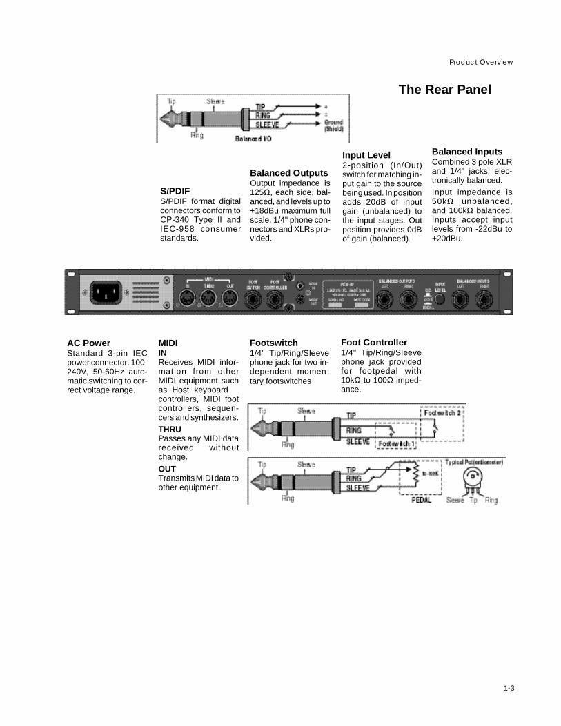
The Rear Panel
AC PowerStandard 3-pin IECpower connector. 100-240V, 50-60Hz auto-matic switching to cor-rect voltage range.
MIDIINReceives MIDI infor-mation from other MIDI equipment such as Host keyboard controllers, MIDI foot controllers, sequen-cers and synthesizers.THRUPasses any MIDI data received without change.
OUTTransmits MIDI data to other equipment.
Footswitch1/4" Tip/Ring/Sleevephone jack for two in-dependent momen-tary footswitches
S/PDIFS/PDIF format digitalconnectors conform toCP-340 Type II andIEC-958 consumerstandards.
Input Level2-posit ion (In/Out)switch for matching in-put gain to the sourcebeing used. In positionadds 20dB of inputgain (unbalanced) tothe input stages. Outposition provides 0dBof gain (balanced).
Balanced InputsCombined 3 pole XLRand 1/4" jacks, elec-tronically balanced.Input impedance is50kΩ unbalanced,and 100kΩ balanced.Inputs accept inputlevels from -22dBu to+20dBu.
Foot Controller1/4" Tip/Ring/Sleevephone jack providedfor footpedal with10kΩ to 100Ω imped-ance.
Balanced OutputsOutput impedance is125Ω, each side, bal-anced, and levels up to+18dBu maximum fullscale. 1/4" phone con-nectors and XLRs pro-vided.

LexiconPCM 80 User Guide
1-4
Installation Notes
Mounting
The PCM 80 is equipped with a 3-pin IEC power connector and detachable cord.
The PCM 80 will operate with power sources from 100 to 240 volts AC, 50-60Hz.Power switching to actual line voltage is automatic.
Power Requirements
Audio Connections Analog AudioFor best performance, maintain balanced connections, and use high-quality,low-capacitance, twisted-shielded pair cable.
When connecting to single-ended, unbalanced devices, connect the low side tosignal ground at the unbalanced piece of equipment. Output level does notchange when connected to an unbalanced input.
Mono ApplicationsUse a Y-connector inserted at the analog inputs and outputs to have the signalsummed to mono.
NOTEBe careful to keep input and output to all channels wired consistently. Out-of-phase wiring can produce audible effects.
Digital AudioS/PDIF (CP-340 Type II) Consumer Digital Audio I/O. 75Ω coaxial cable suitedfor digital audio or video signals is required. Audio grade cable is not suitable.
Footswitch/Foot ControllerOne 1/4 inch T/R/S phone jack is provided for 2 momentary footswitches.Another 1/4 inch T/R/S phone jack is provided for a footpedal (minimum 100Ωto maximum 10k impedance). Normally open or normally closed momentaryswitches are suitable. At power on, the PCM 80 assumes the switch is off. Useshielded, twisted-pair cable with shield connected to sleeve. See diagram onprevious page.
MIDI5-pin DIN connectors are provided for MIDI IN, THRU and OUT. Use standard5-pin DIN MIDI cable assemblies, available from your local dealer.
The PCM 80 uses one EIA-standard rack space, and can be mounted on anylevel surface or in a standard 19 inch (483 mm) rack. If the PCM 80 is mountedin a rack or road case, support the rear of the chassis to prevent possibledamage from mechanical shock and vibration.
The maximum ambient operating temperature is 104°F (40°C). Provide ade-quate ventilation if the PCM 80 is mounted in a closed rack with heat-producingequipment such as power amplifiers.
Control Connections
1-5
Product Overview
The PCM 80, with both analog and digital input and output connections, requiressome attention to proper setting of signal level.
Analog inputs are first gain-conditioned by the rear panel input gain switch, andthen by the front panel INPUT knob. Proper setting of both the switch and knobare important for best performance of the A/D converter. Audio data from the A/D converter is level adjusted by the Analog Lvl parameter before reaching theeffects processors. Digital inputs are also level adjusted before reaching theeffects processors via the Digital Lvl parameter.
Analog and digital sources are mixed at the input to the effects processors. Forexample, setting both Analog Lvl and Digital Lvl to 50% will mix the analog anddigital input signals equally and send them to the effects. Creating a mix whichexceeds 100% can cause overload.
Proper setting of Input level on the PCM 80 is dependent on:
• Proper signal level into the analog front end to avoid signals causing overloadat the DSP input
• Proper adjustment of the signal level into the analog-to-digital converter tooptimize noise and avoid overload
• Proper setting of signal level into the digital signal processor to optimizenoise.
Headroom DisplayThe headroom display provides both headroom and overload information froma variety of measurement points. The meters display the sum of both the analogand the digital input data. Examining either the analog or the digital level alonerequires that the Level parameter of the subject data stream be set to 100%,while the Level parameter of the other is set to 0%.
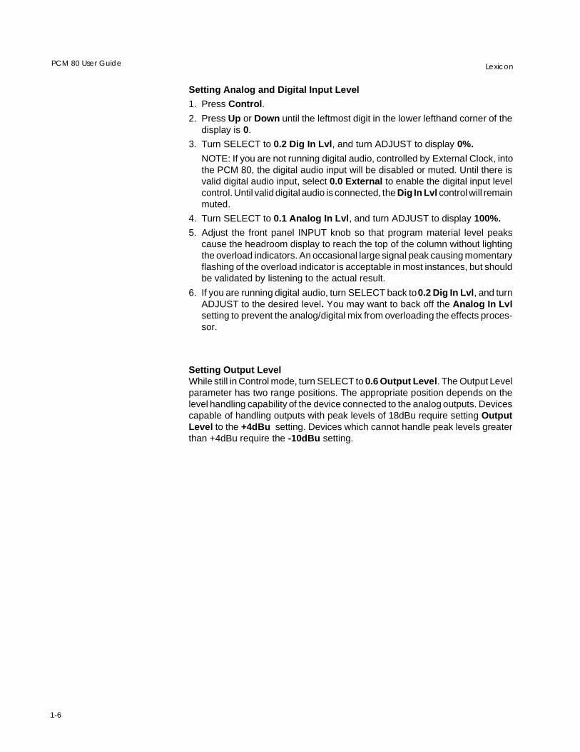
The chart below illustrates the adjustment range that will set input levels for bothbalanced and unbalanced operation.When a choice can be made, it is best tooperate at the higher amplitude end of the recommended range to optimizenoise performance.
Setting Audio Levels
Overload
The 0db (overload) indicators will light under the following conditions:
• A/D overload• overload at any point in effects processing
For example, internal peaking of high Q filters, or level buildup from certainreverberation modes can result in overload, even when the input A/D or digitalreceiver data stream is not at full scale. Such conditions are most often causedby a combination of extreme parameter settings. Adjusting parameter/levelsettings can eliminate these overload conditions.
Unbalanced Balanced
overload: > 0dBu >+20dBu
acceptable: 0dBu to -22dBu +20dBu to -2dBu
too low (noisy): <-22dBu <-2dBu
LexiconPCM 80 User Guide
1-6
Setting Analog and Digital Input Level
1. Press Control.
2. Press Up or Down until the leftmost digit in the lower lefthand corner of thedisplay is 0.
3. Turn SELECT to 0.2 Dig In Lvl, and turn ADJUST to display 0%.
NOTE: If you are not running digital audio, controlled by External Clock, intothe PCM 80, the digital audio input will be disabled or muted. Until there isvalid digital audio input, select 0.0 External to enable the digital input levelcontrol. Until valid digital audio is connected, the Dig In Lvl control will remainmuted.
4. Turn SELECT to 0.1 Analog In Lvl, and turn ADJUST to display 100%.
5. Adjust the front panel INPUT knob so that program material level peakscause the headroom display to reach the top of the column without lightingthe overload indicators. An occasional large signal peak causing momentaryflashing of the overload indicator is acceptable in most instances, but shouldbe validated by listening to the actual result.
6. If you are running digital audio, turn SELECT back to 0.2 Dig In Lvl, and turnADJUST to the desired level. You may want to back off the Analog In Lvlsetting to prevent the analog/digital mix from overloading the effects proces-sor.
Setting Output LevelWhile still in Control mode, turn SELECT to 0.6 Output Level. The Output Levelparameter has two range positions. The appropriate position depends on thelevel handling capability of the device connected to the analog outputs. Devicescapable of handling outputs with peak levels of 18dBu require setting OutputLevel to the +4dBu setting. Devices which cannot handle peak levels greaterthan +4dBu require the -10dBu setting.

1-7
Product Overview
Effects Send (R)
Effects Send (L)
Channel Input orEffects Return (L)
Channel Input orEffects Return (R)
Configurations
Connection to amixing console'seffects sends
If you will be using a PCM 80 as your primary effects unit, and your systemincludes a console with one or more auxiliary (effects) sends, connect the PCM80 as shown above. In most applications, it is preferable to connect the PCM80 outputs to two of the console's input channel strips, panned full left and right,rather than to the effects returns. This allows the greatest flexibility in routing andequalization.
In this configuration the console controls are used to set the amount of effectheard—the PCM 80's MIX control should be set for 100% wet. To assign a globalMIX setting:
1. Press Control.
2. Press Up or Down until 1.x is displayed in the lower left of the display andSystem is displayed on the upper line.
3. Turn SELECT until System Mix Mode is displayed on the upper line. 1.1 willbe displayed in the lower left.
4. Turn ADJUST until the lower line reads:
1.1 Global
5. Press Load / to show the current global setting of MIX; use ADJUST to setit to 100% wet.
LexiconPCM 80 User Guide
1-8
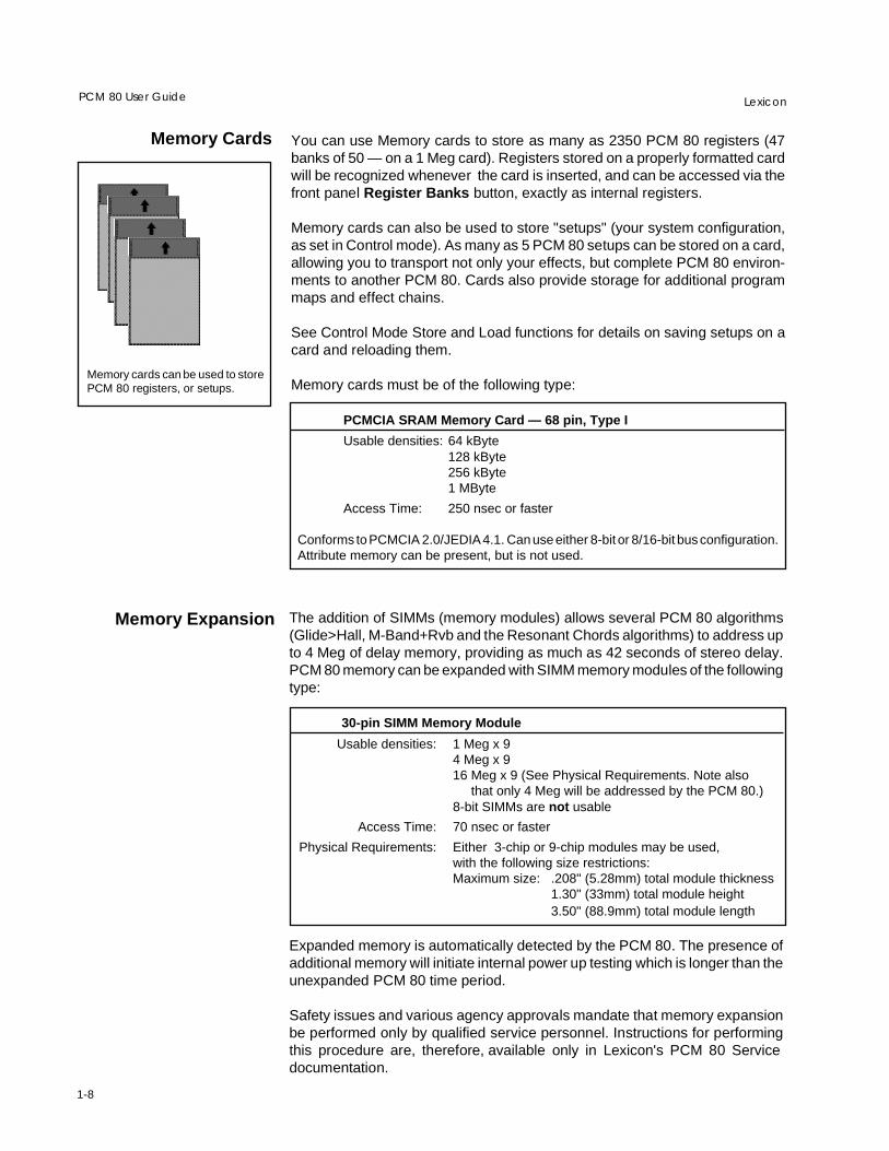
You can use Memory cards to store as many as 2350 PCM 80 registers (47banks of 50 — on a 1 Meg card). Registers stored on a properly formatted cardwill be recognized whenever the card is inserted, and can be accessed via thefront panel Register Banks button, exactly as internal registers.
Memory cards can also be used to store "setups" (your system configuration,as set in Control mode). As many as 5 PCM 80 setups can be stored on a card,allowing you to transport not only your effects, but complete PCM 80 environ-ments to another PCM 80. Cards also provide storage for additional programmaps and effect chains.
See Control Mode Store and Load functions for details on saving setups on acard and reloading them.
Memory cards must be of the following type:
PCMCIA SRAM Memory Card — 68 pin, Type I
Usable densities: 64 kByte128 kByte256 kByte1 MByte
Access Time: 250 nsec or faster
Conforms to PCMCIA 2.0/JEDIA 4.1. Can use either 8-bit or 8/16-bit bus configuration.Attribute memory can be present, but is not used.
Memory cards can be used to storePCM 80 registers, or setups.
Memory Cards
The addition of SIMMs (memory modules) allows several PCM 80 algorithms(Glide>Hall, M-Band+Rvb and the Resonant Chords algorithms) to address upto 4 Meg of delay memory, providing as much as 42 seconds of stereo delay.PCM 80 memory can be expanded with SIMM memory modules of the followingtype:
30-pin SIMM Memory Module
Usable densities: 1 Meg x 94 Meg x 916 Meg x 9 (See Physical Requirements. Note also that only 4 Meg will be addressed by the PCM 80.)8-bit SIMMs are not usable
Access Time: 70 nsec or faster
Physical Requirements: Either 3-chip or 9-chip modules may be used,with the following size restrictions:Maximum size: .208" (5.28mm) total module thickness
1.30" (33mm) total module height3.50" (88.9mm) total module length
Expanded memory is automatically detected by the PCM 80. The presence ofadditional memory will initiate internal power up testing which is longer than theunexpanded PCM 80 time period.
Safety issues and various agency approvals mandate that memory expansionbe performed only by qualified service personnel. Instructions for performingthis procedure are, therefore, available only in Lexicon's PCM 80 Servicedocumentation.
Memory Expansion

2-1
Basic Operation
2Basic Operation
The PCM 80 provides a wide range of control over an extraordinary set of reverband modulation effects. All of the controls are easily accessed from the frontpanel and are described in detail in this section.
The PCM 80 has five basic modes of operation, each of which is selected bypressing a front panel button (Program Banks, Register Banks, Edit, Controland Tempo). Each of these first four mode buttons has an LED which lights whenthe mode is active. The Tempo LED (unless you elect to have this function turnedoff) flashes the current tempo. When Tempo mode is active, no other modeLEDs will be lighted.
Modes of Operation
The five mode buttons give you the first level of access to all of the functions andparameters in the PCM 80.
• Press Program Banks repeatedly to access four banks of factory presetprograms. Each bank contains 50 programs.
• Press Register Banks to access a bank of 50 memory locations, calledregisters, where you can store your customized effects. Memory cards canbe used for storage of additional banks of registers. When a formattedmemory card containing stored registers is inserted, pressing RegisterBanks repeatedly will cycle through all of the available register banks.
• Press Edit to access all of the available parameters for the currently runningeffect.
• Press Control to select system parameters, MIDI, card formatting, etc.
• Press Tempo to set tempo-related values that affect the delay time and LFOrate parameters of the currently-running effect. This is an exciting featurewhich is unique to the PCM 80, and which will be described in detail later inthis chapter.
The PCM 80 is always operating in one of these modes.Here, the lighted LED indicates that Control mode is active.

LexiconPCM 80 User Guide
2-2
All of the controls available in a mode are arranged in a matrix of up to 10 columns(numbered 0-9) and 10 rows (each numbered .0-.9). This arrangment allows anyone of as many as 100 parameters to be selected simply by using the SELECTknob and the Up and Down buttons to select a position in the matrix.
Navigating a Matrix
→←
↑
↓
Simultaneously pressingUp and Down will alwaysreturn you to 0.0
The SELECT knob moves youhorizontally across the matrix.
In the Program and Register Banks, the ADJUST knob actsas a soft knob for adjustment of one or more patched effectparameters. In the other modes, ADJUST scrolls through therange of available settings for the control you have selected.
The Up and Downbuttons move youvertically throughthe rows of thematrix.
XXXXXXX XXXXXXXXXX
3.6 XXXXXXXXXXXXXXXXX
Your current location in the matrix is shownin the lower lefthand corner of the display.
An asterisk in the display indicates thatLoad / is active and, depending on themode, will load effects or displayadditional parameters when pressed.
Go or Pro The PCM 80 offers a choice between two levels of Edit mode parameter access.We call these Go mode and Pro mode.
Go mode makes use of an extra row in the edit mode matrix called the Soft Row,where you can assign as many as 10 effect parameters for easy access.Selecting Go mode (Control mode 1.0) limits the action of the Edit button todisplaying only the Soft Row parameters assigned to the current effect.
Each preset has a set of Soft Row assignments which we've selected for you (aswell as an assignment for the ADJUST knob). When shipped, the PCM 80 willpower up in Go mode with the first preset (P0 0.0) loaded. Press Edit to displaythe Soft Row of parameters.
Pro mode gives you access to the full parameter matrix, including the Soft Row.Use this mode when you want to do in-depth effects editing or patching, or whenyou want to customize Soft Row assignments.
Go mode and Pro mode selection is made in Control mode at matrix location 1.0.

2-3
Basic Operation
InfoThe PCM 80 offers an extensive set of informative display messages which canbe activated from the front panel.
The front panel switches perform various functions when pressed. Most of thesefunctions are activated on release of the button. If you want to know more aboutthe function of a particular button (without actually executing any action) pressand hold the button down. While you are holding down the button, an explanatorymessage will appear on the display. The activation of an Info message overridesthe normal function of the button, so that no action is taken on release.
Displays the current functionassigned to the Up button andthe ADJUST knob.
Displays the current functionassigned to the Down buttonand the SELECT knob.
Displays the currently loadedeffect name,bank, and matrixlocation.
Displays the type of systembypass currently selected,and the current status (onor off).
Info messages are displayed when a button is pressed andheld down. Generally, Info messages inform you of thefunction of a button, or provide current status information.
Displays action needed toperform a store operation orMemory Protect message whenstore function is disabled.
Inactive until an effect has beenaltered, then displays "Press tohear stored effect"
Displays the current tempo and theclock source (MIDI or Internal).
LexiconPCM 80 User Guide
2-4
Control Mode Selections of various system states and conditions are made in Control Mode.Press Control to enter this mode. The Control button LED will light to indicatethat the mode is active. Note that Control Mode functions are not available whenthe Compare function is active.
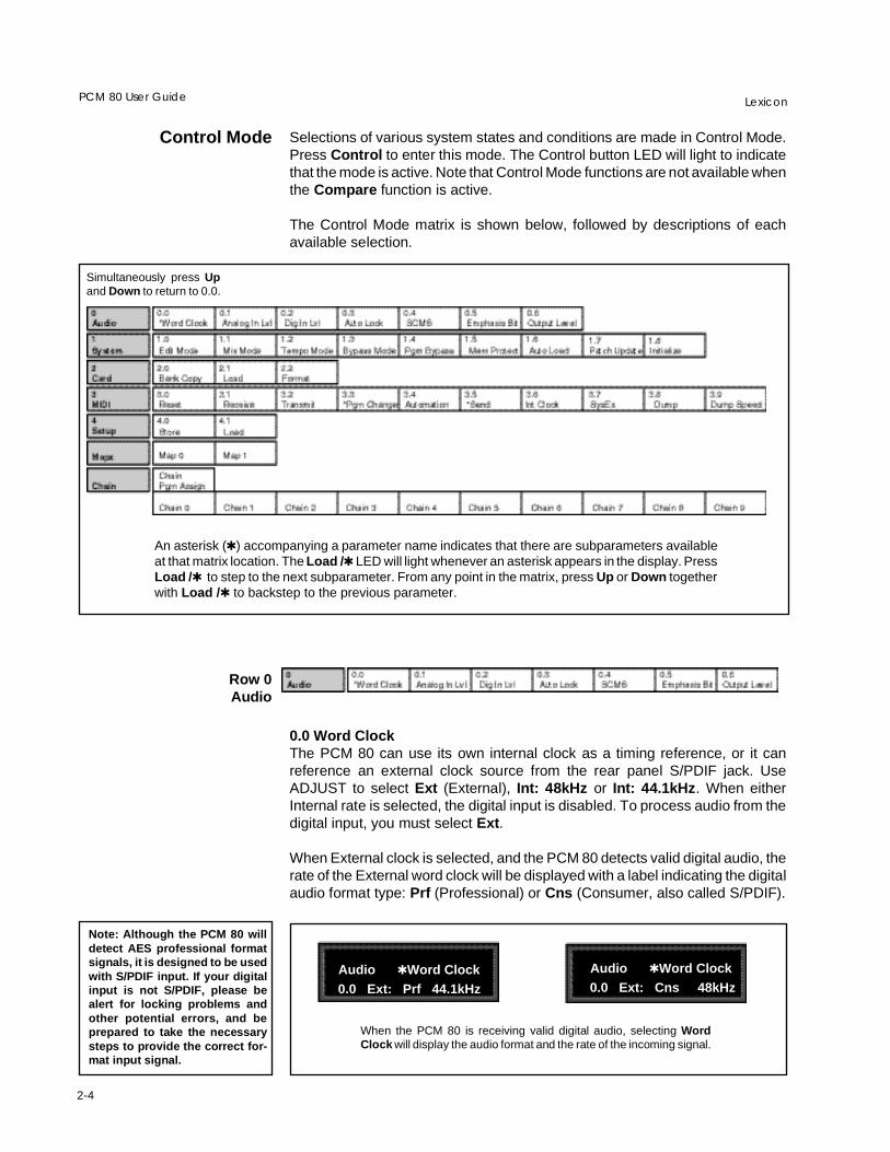
The Control Mode matrix is shown below, followed by descriptions of eachavailable selection.
0.0 Ext: Prf 44.1kHz
Audio Word Clock0.0 Ext: Cns 48kHz
When the PCM 80 is receiving valid digital audio, selecting WordClock will display the audio format and the rate of the incoming signal.
Audio Word Clock
Row 0Audio
0.0 Word ClockThe PCM 80 can use its own internal clock as a timing reference, or it canreference an external clock source from the rear panel S/PDIF jack. UseADJUST to select Ext (External), Int: 48kHz or Int: 44.1kHz. When eitherInternal rate is selected, the digital input is disabled. To process audio from thedigital input, you must select Ext.
When External clock is selected, and the PCM 80 detects valid digital audio, therate of the External word clock will be displayed with a label indicating the digitalaudio format type: Prf (Professional) or Cns (Consumer, also called S/PDIF).
Simultaneously press Upand Down to return to 0.0.
An asterisk () accompanying a parameter name indicates that there are subparameters availableat that matrix location. The Load / LED will light whenever an asterisk appears in the display. PressLoad / to step to the next subparameter. From any point in the matrix, press Up or Down togetherwith Load / to backstep to the previous parameter.
Note: Although the PCM 80 willdetect AES professional formatsignals, it is designed to be usedwith S/PDIF input. If your digitalinput is not S/PDIF, please bealert for locking problems andother potential errors, and beprepared to take the necessarysteps to provide the correct for-mat input signal.

2-5
Basic Operation
When External clock is first selected, the PCM 80 will repeatedly try to establishlock. You can choose to have any subsequent interruptions of the incomingdigital audio signal dealt with in one of two ways. An Auto Lock feature allowsyou to choose to have the PCM 80 attempt to re-establish lock, or not. (See 0.3Auto Lock.) In either case, the PCM 80 will immediately mute the digital input,and switch to Internal clock at the sample rate of the last valid external signal.
When External clock is selected, any loss of lock detected in the incoming digitalaudio, or reception of non-audio data will cause the digital input to be muted. Anerror message will be displayed if this occurs.
The following types of errors are detected when the PCM 80 is set to Ext:
No Lock: The PCM 80, at some point, lost lock to the incoming digitalaudio signal. Digital audio input is muted.
Out of Range: The sampling rate of the incoming audio signal is outside ofacceptable tolerance limits of +4%. Digital audio input ismuted.
Non Audio: Indicates transmission of non-audio data, such as from a CDROM. Digital audio input is muted.
Dig In StatusPressing Load/ from Word Clock will display the current digital input status.This status display is continuously updated, acting as a real-time monitor of thePCM 80 digital input. This display is active even when the PCM 80 is set toInternal clock. Note that in the case of an AES Pro format signal, "Emphasis"means either CCITT or 50/15µs emphasis.
If valid digital audio is detected, the display will show the external clock rate andformat information, along with the status of the Emphasis bit(s) in the incomingaudio signal. If the PCM 80 has lost lock, the display message will indicate "NoLock" and parenthetically show the internal clock rate now in use.
Audio *Dig In Status
0.0 Prf 44.1 Emp:Yes
Audio *Dig In Status
0.0 NoLock (Int:44.1)
When the PCM 80 loses lock, it will mute the digital input and switch to Internal Clock.
Error Log
The following errors are continuously logged and are available for review bypressing Load/ from the Dig In Status display and using ADJUST to scrollthrough the error list.
Validity: A Validity error indicates that the Validity bit was set in a frameof incoming data and that the data attached to it may becorrupted. This bit may also be sent when the transmitting deviceis paused.
Confidence: The PCM 80 is detecting excessive jitter or noise on the digitalaudio line. No data has been corrupted, but corrective actionshould be taken.
Upon loss of lock, or reception of non-audio data, the PCM 80 will mute thedigital input and display the followingmessages when Word Clock or Dig InStatus is selected:
Word Clock Dig In Status
Not Locked No Lock (Int 44.1)
Out of Range No Lock (Int 44.1)
Non Audio: 44.1 Non Audio: 44.1

LexiconPCM 80 User Guide
2-6
SlipSample:
CRC:
Parity, Biphase:
Indicates that a single sample is misaligned with the window defined by the Word Clock. This may occur when an external Host changes sample rate, or when it is just powering up, but should not occur in normal operation.
Indicates a Cyclic Redundancy Check error in the incoming data.
Indicate that at least one bit (and therefore at least one audio sample) was corrupted.
Parity, Biphase, and Confidence errors are most often caused by inappropriate cabling. Be sure to use 75Ω video-grade cable, kept as short as possible — standard audio cable will not work reliably.
Each error is reported by name, with the number of occurrences of that particulartype of error. The display might show, for example "CRC: 4752". As many as9999 instances of each error can be shown. If the number of actual errorsexceeds 9999, the display will indicate ">9999". A special symbol () before theerror type indicates the most recently received error.
Press Load/ from the Dig In Status display and use ADJUST to scroll through the ErrorLog.
Audio *Error Log
0.0 CRC >9999
A typical Error Log display showing that the lasterror received was a CRC error ( CRC) andthat there have been more than (>) 9999 in-stances of CRC errors since Word Clock waslast set to Ext.
To clear the Error Log, reselect Ext from the Control Mode Word Clock display. This will cause the PCM 80 to attempt to lock to the current external source and will reset the Error Log. The log is also cleared on power up, and whenever it relocks (Auto Lock On).
0.1 Analog In LvlThis is a Host level control for analog left and right inputs. Use ADJUST to select values from 0-100%. If using only analog inputs, this should be 100% for best audio performance. Values between 0% and 100% are for mixing analog and digital sources.
Note: If the analog signal being fed into the PCM 80 is too hot, turn it down by adjusting the front panel INPUT level control, or by changing the rear panel Input Gain switch. (See Setting Audio Levels in Chapter 1.)
0.2 Dig In LvlThis is a Host level control for digital left and right inputs (post A/D converter). Use ADJUST to select values from 0-100%. If using only digital inputs, this should be 100%, with Analog InLvl set to 0% for best audio performance. Values between 0% and 100% are for mixing analog and digital sources.

2-7
Basic Operation
If digital audio is interrupted by lock or range errors, or by transmission of non-audio data, the digital input will be muted. Whenever this occurs, the PCM 80remains functional, while an error message, such as those shown below, isdisplayed.
Error : Out Of Range
(Press any button)Error : Lock
(Press any button)
Error : Non Audio
(Press any button)
Any such message will remain on the display until you dismiss it by pressing anyfront panel button. If the condition causing the error is corrected, and the digitalinput is unmuted, the message will still remain until you dismiss it to ensure thatyou are informed of a condition that has muted digital audio, even if only for a briefperiod of time. Once the message is dismissed, the display will return to itsprevious state.
Some errors detected in an incoming digitalaudio signal will cause the PCM 80 to mute thedigital input. When this happens, the Dig In Lvldisplay will show both the level you selected,and the fact that the signal is muted.
Audio Dig In Lvl
0.2 30% (Muted)
If you select the Dig In Lvl parameter while there is a lock, range, or non-audioerror, the display will continue to show the level you have selected, andparenthetically show that the signal has been muted.
Note, if Word Clock is set to Int, Dig In Lvl is disabled. You must select Ext toprocess digital audio.
0.3 Auto LockWhen Word Clock is set to Ext, and the PCM 80 loses lock with an incomingdigital audio signal, it will immediately switch to Internal Clock at the sample rateof the digital signal last detected. The Auto Lock control allows you to choosewhether or not the PCM 80 will continuously try to re-establish lock. UseADJUST to select On (continuous retry), or Off (continue to use Internal Clockas a timing reference until Ext is reselected).
0.4 SCMSDigital audio signals, in order to comply with copyright standards, are encodedwith control information which can limit the ability to copy audio data. This controlinformation is generally known as SCMS (Serial Copy Management System).Under this system, you can choose to have the audio material processed by thePCM 80 encoded to allow one of three levels of copy restriction. To make yourselection, use ADJUST to select No Copy, One Copy, or Multi Copy.

LexiconPCM 80 User Guide
2-8
0.5 Emphasis BitThe Emphasis control allows you to explicitly set the emphasis "flag" in the digitalaudio, or to pass along the incoming signal without changing its emphasiscoding. (The PCM 80 does not perform any emphasis or de-emphasis as partof its signal processing.) The choices available with ADJUST are: Yes, No, andPass Thru.
0.6 Output LevelThis control allows you to select the maximum output level at the PCM 80'sanalog outputs. Use ADJUST to select +4 dBu, or –10 dBu.
Exercise care when switching this control, as a 14dB level changeinstantly occurs when going from -10dBu to +4dBu.
Row 1System
1.0 Edit ModeThe PCM 80 has been designed with a "plug and play" feature called Go mode.In this mode, the most useful parameters of each effect are grouped together ina single row which is available whenever you press Edit.
Each PCM 80 preset has a set of Go mode parameters which we've selected foryou. When shipped, the PCM 80 will power up in Go mode, with the first preset(P0 0.0) loaded. Press Edit to display the first available parameter in the SoftRow.
If you want access to the full parameter matrix for any effect, including the SoftRow parameters, use ADJUST to select Pro mode. Now, when Edit is pressed,you can select any parameter for adjustment, and customize any effect with yourown Soft Row assignments. For more information about the Soft Row, seeEditing an Effect later in this chapter.
1.1 Mix ModeEach PCM 80 effect has its own Mix parameter, with the Mix setting stored asan integral part of the effect. Mix Mode allows you to override these individualMix settings and set a global Mix value for all effects. This is useful when usinga mixing console's controls to set the amount of wet signal in a mix. In such acase, you can use this control to set all PCM 80 effects to 100% wet.
When shipped, the PCM 80 has the Mix Mode set to Pgm. This settingdetermines that effects will be loaded with their stored Mix settings, and allowsthe individual Mix controls in the edit matrix of each effect to be adjusted from0-100% Wet. To set a global Mix value, use ADJUST to select Global, pressLoad/ to display the current value, and use ADJUST to assign any value from0-100% Wet.

2-9
Basic Operation
1.2 Tempo ModeThe PCM 80 gives you an exciting new approach to working with delay times andmodulation parameters. Now you can set these parameters in beats, allowingyou to control your effects in a completely musical way. Each PCM 80 effect hasits own Tempo parameters, with tempo settings stored as an integral part of theeffect. These include: Tempo Rate, Tempo Beat, Tempo Source (internal orMIDI), Tap Duration, and Tap Average. The Global setting here allows you tooverride individual Tempo Rate settings with a global value which can then bechanged on the fly.
When shipped, the PCM 80 has the Tempo Mode set to Pgm, with each effectdriven by its own stored tempo rate. To change to a global Tempo Rate, useADJUST to select Global, press Load/ to display the current tempo in BPM(beats per minute), then use ADJUST to assign a global tempo value of 40-400BPM.
Whether Tempo Mode is set to Global or Pgm, you can set a new tempo rateby pressing the front panel Tap button twice. Alternatively, you can choose tohave tempo set automatically from incoming MIDI clock. The rate you tap, or theMIDI tempo, will be displayed here.
For more information about working with the tempo parameters, see TempoMode later in this chapter.
1.3 Bypass Mode/Bypass SrcThis control alows you to determine the behavior of the PCM 80 when the frontpanel Bypass button is pressed. You can also assign an external controller toperform identically to the front panel button. When the Bypass button is pressed,the LED will light, and a message indicating bypass type will be displayed.Pressing Bypass again will turn bypass off.
The choices available via ADJUST are:
AllMute: Mutes both the input and the output signal, giving com-plete silence.
InputMute: Mutes the input to the PCM 80, allowing the tail of theeffect to ring out. (This is the default setting.)
OutputMute: Mutes the output. Audio signals are still being fed to thePCM 80, so processed audio returns immediately whenBypass is turned off.
Bypass: Completely bypasses the PCM 80, passing unproc-essed audio directly through to the outputs.
To assign an external controller to perform the selected bypass function, pressLoad/ to display Bypass Src. Use ADJUST to select a footswitch or any MIDIcontroller (or Off). Once a source is selected, it will perform the same functionassigned to the front panel Bypass button.
1.4 Pgm BypassThis control allows you to determine the behavior of the PCM 80 when a neweffect is loaded. The choices available are: AllMute or Bypass.

LexiconPCM 80 User Guide
2-10
1.5 Mem ProtectThe PCM 80 provides a memory protection feature to prevent accidentaloverwriting of your stored effects. When this control is set to On, pressing thefront panel Store button will cause an error message to be displayed. To enablethe Store function, turn ADJUST to select Off.
1.6 Auto LoadThis control allows you to choose whether PCM 80 effects will be loadedimmediately when selected with SELECT and the Up and Down buttons (On),or whether they will require a press of the Load/ button (Off).
1.7 Patch UpdateWhen a controller is patched to an effect parameter, this control determineswhen the controller will take control of the parameter. If Immediate is selected,stored parameter values will jump to the current controller position when theeffect is loaded. If Delayed is selected, the stored parameter value will remainin effect until the controller is moved. See Patching later in this chapter.
1.8 InitializeSelecting this control arms the PCM 80 to revert to its factory settings.
This will erase all registers and setups,and return the PCM 80 to its default states.
If you press Store, the display will ask "Are you sure?" (Press STORE). If youdon't want to reinitialize your unit, press any button to cancel the operation. If youpress Store in response to this message, the display will flash "Restoringoriginal factory settings" and your unit will be reinitialized.

2-11
Basic Operation
Row 2Card
2.0 Bank CopyThis control allows you to copy banks of effects from one location to another.Banks can be copied internally, or to and from PCMCIA Memory Cards. Try, forexample, copying Preset Bank 0 into the internal Register Bank.
1. Press Store. The following display will appear briefly.
The display will then change to show:
Select and copy
effect banks
Card Bank Copy
2.0 Src: P0 Dst: R
The asterisk indicates that Src is available for adjustment. ADJUST willscroll through all available banks, including internal preset and registerbanks, as well as any banks on inserted PCMCIA cards. Internal banks arelabeled "P0...P3" and "R1". Card registers will be labeled "C0, C1, C2" etc.
2. Press Load/ to move the asterisk to Dst.
Card Bank Copy
2.0 Src: P0 Dst: R
Now, use ADJUST to select the destination of your copy. Selecting aregister bank here will cause its contents to be erased and overwrittenwith the bank you have selected as the source when Store is pressed.
4. Press Store to copy the selected source (in this case Preset Bank 0) into theinternal Register Bank. The display will ask "Are you sure?" (Press STORE).Press any button to cancel. Press Store to complete the store operation.
2.1 LoadThis control is provided for future enhancement. It will allow you to load audiosoftware from a Memory Card simply by inserting the new card and respondingto the display prompts.
LexiconPCM 80 User Guide
2-12
2.2 FormatThis control allows you to format a Memory Card for PCM 80 use. Press Storeand insert an unformatted card (or one you don't mind erasing). Make sure theWrite Protect latch on the card is set to Off. Press Store. The display will ask"Are you sure?" (Press STORE). Press Store. The following display will appearbriefly.
This display allows you to assign a name (of 10 characters or less) to the card.A blinking cursor indicates that a particular character is available for changing.Use ADJUST to select the character you want in that position. Turn SELECT tomove the cursor to another character. Press Store to execute. The display willask "Are you sure?" (Press STORE). Press Store again to complete theoperation. Press any front panel button to cancel.
Format and name
memory card
Card Name: New Card
(press STORE)
The display will then change as shown below.
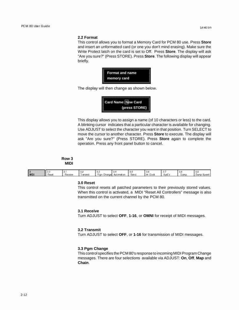
Row 3MIDI
3.0 ResetThis control resets all patched parameters to their previously stored values.When this control is activated, a MIDI "Reset All Controllers" message is alsotransmitted on the current channel by the PCM 80.
3.1 ReceiveTurn ADJUST to select OFF, 1-16, or OMNI for receipt of MIDI messages.
3.2 TransmitTurn ADJUST to select OFF, or 1-16 for transmission of MIDI messages.
3.3 Pgm ChangeThis control specifies the PCM 80's response to incoming MIDI Program Changemessages. There are four selections available via ADJUST: On, Off, Map andChain.

2-13
Basic Operation
Pgm+ and Pgm –, are available as subparameters in each location. Pgm+ willload the next higher effect in the current bank, map , or chain. Pgm – will loadthe next lower effect. You can select the following sources to activate Pgm+ andPgm –:
OffFootswitch 1Footswitch 2•••MIDI Controller #119
OnProgram Change messages 0—49 correspond to PCM 80 Effects 0.0 —4.9 inthe current bank. Program Change messages 50—127 are ignored. The currentbank can be changed with MIDI Bank Select Messages as follows:
0–3: Program Banks 0–34: Internal Register Bank
5–9: reserved10–56: Memory Card Banks. The number of banks available on a given
card will vary with its size, as follows:
Card Size # Banks
64 2256 11512 23
1 Meg 47
OffAll Program Change and Bank select messages are ignored.
MapProgram Change 0-127 can be mapped to any PCM 80 effect in any internal orcard bank. Two 128 element maps are stored internally, additional maps may bestored on RAM cards. Once you have selected Map, press Load/ to display:
Turn ADJUST to select the desired Program Chain. When set to MIDI, ProgramChains will be loaded by MIDI Program Change messages according to thesettings of Chain Pgm Assign in Row 6.
MIDI Pgm Change
3.3 MapSelect 0
Turn ADJUST to select the desired Program Change Map.
ChainAny Program Change number can be selected to load any one of ten customizedeffect “chains". Additional chains can be stored on RAM cards. Once a chain isloaded, effects in the chain are accessed by the controller patched to Pgm + andPgm – (program increment and program decrement). Once you have selectedChain, press Load/ to display:
MIDI Pgm Change
3.3 Chain MIDI
LexiconPCM 80 User Guide
2-14
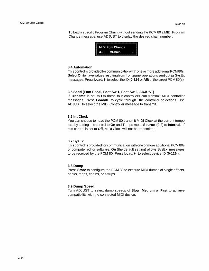
To load a specific Program Chain, without sending the PCM 80 a MIDI ProgramChange message, use ADJUST to display the desired chain number.
3.4 AutomationThis control is provided for communication with one or more additional PCM 80s.Select On to have values resulting from front panel operations sent out as SysExmessages. Press Load/ to select the ID (0-126 or All) of the target PCM 80(s).
3.5 Send (Foot Pedal, Foot Sw 1, Foot Sw 2, ADJUST)If Transmit is set to On these four controllers can transmit MIDI controllermessages. Press Load/ to cycle through the controller selections. UseADJUST to select the MIDI Controller message to transmit.
3.6 Int ClockYou can choose to have the PCM 80 transmit MIDI Clock at the current temporate by setting this control to On and Tempo mode Source (0.2) to Internal. Ifthis control is set to Off, MIDI Clock will not be transmitted.
3.7 SysExThis control is provided for communication with one or more additional PCM 80sor computer editor software. On (the default setting) allows SysEx messagesto be received by the PCM 80. Press Load/ to select device ID (0-126 ).
3.8 DumpPress Store to configure the PCM 80 to execute MIDI dumps of single effects,banks, maps, chains, or setups.
3.9 Dump SpeedTurn ADJUST to select dump speeds of Slow, Medium or Fast to achievecompatibility with the connected MIDI device.
MIDI Pgm Change
3.3 Chain 3
2-15
Basic Operation
Control ModeMatrix Location System Parameter Default Setting
Audio 0.0 Word Clock Internal 48kHz0.1 Analog Lvl 100%0.2 Digital Lvl 0%0.3 Auto Lock Off0.4 SCMS Multi Copy0.5 Emphasis Bit Pass Thru0.6 Output Level +4dBu
System 1.0 Edit Mode Go1.1 Mix Mode Pgm
Global Mix Value 100% Wet1.2 Tempo Mode Pgm
Global Tempo Value 120 BPM1.3 Bypass Mode InputMute
Bypass Src Off1.4 Pgm Bypass AllMute1.5 Mem Protect On1.6 Auto Load Off1.7 Patch Update Delayed
MIDI 3.1 Receive OMNI3.2 Transmit 13.3 Pgm Change On
Pgm+ OffPgm– OffMap select 0Chain MIDI
3.4 Automation Off3.5 Footpedal None
Sw 1 NoneSw 2 NoneADJUST None
3.6 Int Clock Off3.7 SysEx On
Device ID 03.9 Dump Speed Slow
Tempo ModeMatrix Location System Parameter Default Setting
Tempo 0.2 Source Internal
Tap 1.3 Display On
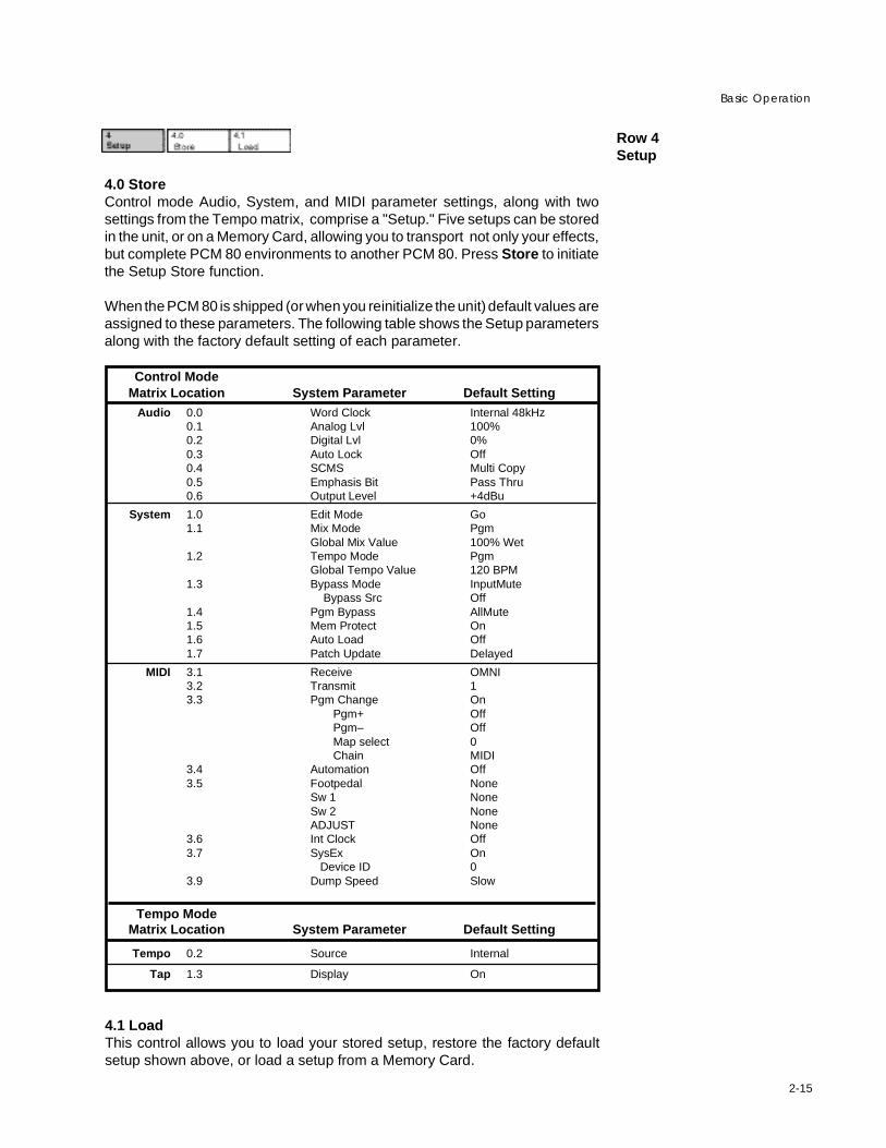
4.1 LoadThis control allows you to load your stored setup, restore the factory defaultsetup shown above, or load a setup from a Memory Card.
Row 4Setup
4.0 StoreControl mode Audio, System, and MIDI parameter settings, along with twosettings from the Tempo matrix, comprise a "Setup." Five setups can be storedin the unit, or on a Memory Card, allowing you to transport not only your effects,but complete PCM 80 environments to another PCM 80. Press Store to initiatethe Setup Store function.
When the PCM 80 is shipped (or when you reinitialize the unit) default values areassigned to these parameters. The following table shows the Setup parametersalong with the factory default setting of each parameter.
LexiconPCM 80 User Guide
2-16
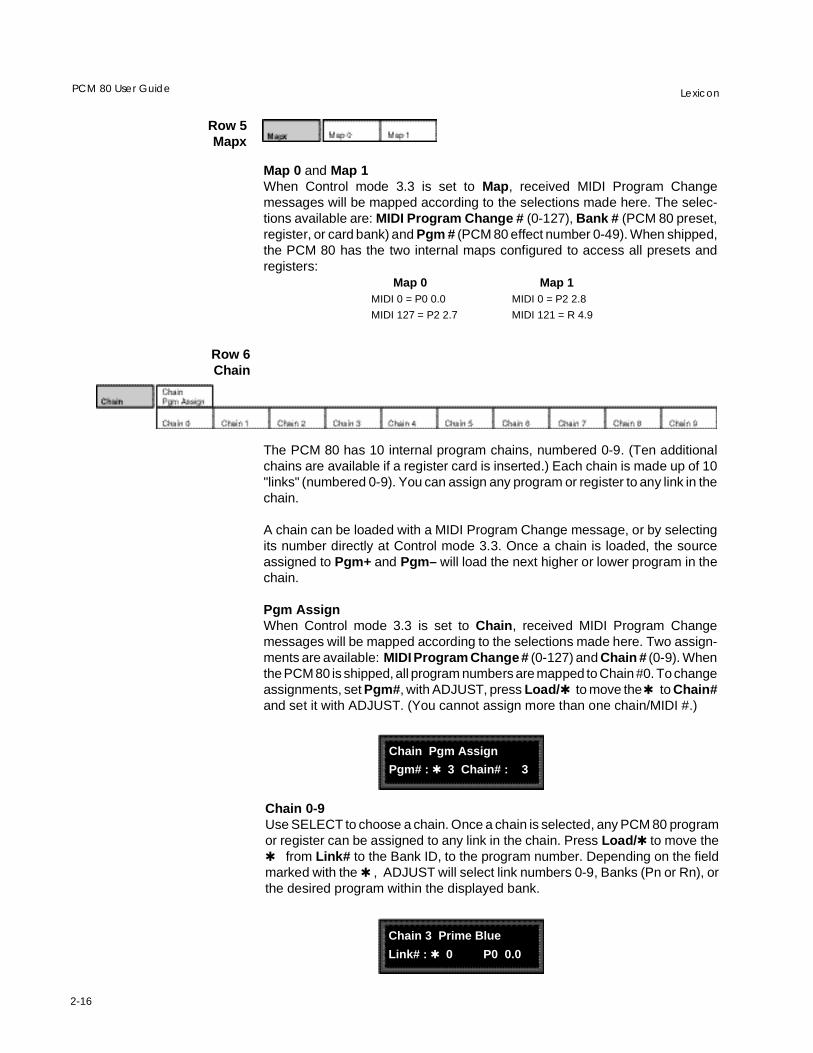
Row 5Mapx
Row 6Chain
The PCM 80 has 10 internal program chains, numbered 0-9. (Ten additionalchains are available if a register card is inserted.) Each chain is made up of 10"links" (numbered 0-9). You can assign any program or register to any link in thechain.
A chain can be loaded with a MIDI Program Change message, or by selectingits number directly at Control mode 3.3. Once a chain is loaded, the sourceassigned to Pgm+ and Pgm– will load the next higher or lower program in thechain.
Pgm AssignWhen Control mode 3.3 is set to Chain, received MIDI Program Changemessages will be mapped according to the selections made here. Two assign-ments are available: MIDI Program Change # (0-127) and Chain # (0-9). Whenthe PCM 80 is shipped, all program numbers are mapped to Chain #0. To changeassignments, set Pgm#, with ADJUST, press Load/ to move the to Chain#and set it with ADJUST. (You cannot assign more than one chain/MIDI #.)
Chain Pgm Assign
Pgm# : 3 Chain# : 3
Chain 0-9Use SELECT to choose a chain. Once a chain is selected, any PCM 80 programor register can be assigned to any link in the chain. Press Load/ to move the from Link# to the Bank ID, to the program number. Depending on the fieldmarked with the , ADJUST will select link numbers 0-9, Banks (Pn or Rn), orthe desired program within the displayed bank.
Chain 3 Prime Blue
Link# : 0 P0 0.0
Map 0 and Map 1When Control mode 3.3 is set to Map, received MIDI Program Changemessages will be mapped according to the selections made here. The selec-tions available are: MIDI Program Change # (0-127), Bank # (PCM 80 preset,register, or card bank) and Pgm # (PCM 80 effect number 0-49). When shipped,the PCM 80 has the two internal maps configured to access all presets andregisters:
Map 0 Map 1MIDI 0 = P0 0.0 MIDI 0 = P2 2.8
MIDI 127 = P2 2.7 MIDI 121 = R 4.9

2-17
Basic Operation
The PCM 80 has 4 Program Banks, each with50 factory-designed programs
A Register Bank provides 50 memory locations forstoring your own effects.
All PCM 80 programs have one or more parameterspatched to the ADJUST knob.
In Program Banks or Register Banks mode, turnADJUST to change the sound of the currentlyrunning effect. While ADJUST is turned, the patchname and value are displayed.
The PCM 80 has 200 factory-designed programs, organized into four ProgramBanks of 50 each, and 50 memory locations, called registers, for storing yourcustomized effects. One Register Bank is available in the PCM 80 itself.Additional Register Banks can be stored on PCMCIA cards.
Program andRegister Banks
Selecting EffectsThe procedure for loading effects is the same, whether you are choosing frombanks of factory presets, or from your own banks of registers. When first turnedon, the PCM 80 will load whatever effect was running when it was last turned off.When shipped from the factory, the first effect in the first Program Bank (P0 0.0Prime Blue) is loaded. The Bank ID (P0, P1, P2, P3 ),matrix location, programname, and the algorithm from which the effect is derived are all displayed.
P0 0.0 Prime Blue
Chorus+Rvb
Matrix Location Program Name
Indicates that the ADJUST knob is patched to one ormore parameters in the currently-running effect — inthis case, Prime Blue.
Algorithm
Press Program Banks to cycle through the program banks. Simultaneouslypress Program Banks along with either Up or Down to backstep.
Turn SELECT to scroll through all of the effects in the bank. Press ProgramBanks to reselect the last displayed effect in another bank. Press Load/ toload the displayed effect.
Program Bank ID
The patch indicator remains to indicate that thecurrently running effect has an ADJUST knobpatch, although the displayed effect may not.
P0 0.1 EkoChorus
Chorus+Rvb
An asterisk in the display indicates thatthe displayed effect is not loaded.
Turn SELECT to display another effect.
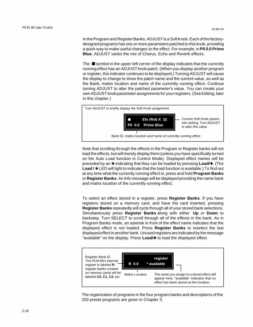
LexiconPCM 80 User Guide
2-18
In the Program and Register Banks, ADJUST is a Soft Knob. Each of the factory-designed programs has one or more parameters patched to this knob, providinga quick way to make useful changes to the effect. For example, in P0 0.0 PrimeBlue, ADJUST varies the mix of Chorus, Echo and Reverb effects.
The symbol in the upper left corner of the display indicates that the currentlyrunning effect has an ADJUST knob patch. (When you display another programor register, this indicator continues to be displayed.) Turning ADJUST will causethe display to change to show the patch name and the current value, as well asthe Bank, matrix location and name of the currently running effect. Continueturning ADJUST to alter the patched parameter's value. You can create yourown ADJUST knob parameter assignments for your registers. (See Editing, laterin this chapter.)
Turn ADJUST to briefly display the Soft Knob assignment
P0 0.0 Prime Blue
Efx /Rvb X 32
Bank ID, matrix location and name of currently running effect
Current Soft Knob param-eter setting. Turn ADJUSTto alter this value.
Note that scrolling through the effects in the Program or Register banks will notload the effects, but will merely display them (unless you have specifically turnedon the Auto Load function in Control Mode). Displayed effect names will bepreceded by an indicating that they can be loaded by pressing Load/. (TheLoad / LED will light to indicate that the load function is available.) To find outat any time what the currently running effect is, press and hold Program Banksor Register Banks. An Info message will be displayed providing the name bankand matrix location of the currently running effect.
To select an effect stored in a register, press Register Banks. If you haveregisters stored on a memory card, and have the card inserted, pressingRegister Banks repeatedly will cycle through all of your stored bank selections.Simultaneously press Register Banks along with either Up or Down tobackstep. Turn SELECT to scroll through all of the effects in the bank. As inProgram Banks mode, an asterisk in front of the effect name indicates that thedisplayed effect is not loaded. Press Register Banks to reselect the lastdisplayed effect in another bank. Unused registers are indicated by the message"available" on the display. Press Load/ to load the displayed effect.
The organization of programs in the four program banks and descriptions of the200 preset programs are given in Chapter 3.
R 0.0 * availableregister
Matrix Location The name you assign to a stored effect willappear here. "available" indicates that noeffect has been stored at this location.
Register Bank IDThe PCM 80's internalregister is labeled R;register banks createdon memory cards will belabeled C0, C1, C2, etc.

2-19
Basic Operation
Tempo ModeThe PCM 80 gives you unique control over tempo. In the PCM 80, tempo is notjust a matter of setting echo rates. Any delay parameter (as many as 10 in someeffects) and any time-based modulator (LFO, Sw1 and Sw2) can be individuallyassigned to an absolute time value, or assigned to a tempo value.
For example, a delay time can be set to a specific number of milliseconds, andyou will always get a delay of that number of milliseconds, regardless of tempochanges. Alternatively, a delay time can be set to a specific ratio of echoes tobeats. Now, if you create a rhythmic echo pattern, delay times will be linked totempo. When you change tempo, the delay time will change to maintain thesame rhythm at the new tempo.
With the LFO and time-based switches, the rate of change can be an absolutevalue (such as once per second), or it can be linked to tempo (for example, onceevery four beats). Any delay parameter, or time-based modulator, can be set toits own individual rhythm, allowing you to set up an effect which will change ina rhythmically interesting way — evolving over time, for example, as opposedto being a mere series of repetitions. Once delays and time-based modulatorsare assigned, tempo rate can be easily changed in a variety of useful ways.
Tempo Rate can be set internally or via MIDI. If Tempo Source is set to Internal,you can dial in any tempo from 40-400 BPM at location 0.0 in the Tempo modematrix. Alternatively, you can press the front panel Tap button twice in rhythmto establish the rate you want, or you can have the value of a patch source actas a tap trigger. (See Patching.) TheTap function, whether performed by thefront panel Tap button, or by an assigned controller, is always active, allowingyou to change tempo on the fly from any mode. You can also choose to have yourtempo transmitted as a MIDI Clock signal to control the tempo of connected MIDIdevices. (Control mode 3.6) If Source is set to MIDI Clock, PCM 80 tempo willsync to incoming MIDI Clock. Whether tempo is set internally or via MIDI, theLED in the Tempo button will flash at the current rate. (You can disable theTempo LED flashing under Tempo mode 1.3.) Press and hold the Tempo buttonat any time to display the current Tempo Rate and Source.
Each effect in the PCM 80 has its own tempo rate setting which is stored with theeffect. You can override these individual tempo rates with a global tempo rateat Control Mode 1.2. Tempo is also available as an independent patch sourcewhich can control any effect parameter. (See Patching later in this chapter.)
When Compare is on, Tapwill not alter the tempo, butwill still reset the LFO's. SeeChapter 3 Modulation.

LexiconPCM 80 User Guide
2-20
Press Tempo to access the following tempo parameters:
Simultaneously press Upand Down to return to 0.0.
An asterisk () accompanying a parameter name indicates that there aresubparameters available at that matrix location. The Load / LED will light wheneveran asterisk appears in the display. Press Load / to step to the next subparameter.
From any point in the matrix, press Up or Down together with Load / to backstep tothe previous parameter.
0.0 RateThis is the current tempo (in Beats Per Minute). When 0.2 is set to Internal,turning ADJUST allows you to select a different rate (40-400 BPM). The TempoLED will flash at the new rate. Note that fractional tempos can be tapped in, butare not available via ADJUST. The display will always show the nearest wholenumber value.
0.1 BeatValueTempo is expressed in BPM. This control allows you to specify the value of thebeat. Eighth, dotted-eighth, quarter, dotted-quarter, half, dotted-half, and whole-note values are available. If, for example, the rate is 120 BPM, and you selecteighth-note here, the tempo will be 120 eighth-notes per minute. If you selectquarter-note here, the tempo will be 120 quarter-notes per minute. (The factorydefault is quarter-note.)
0.2 SourceYou can choose to have tempo determined by the PCM 80 Tap and Ratecontrols (Internal), or by MIDI Clock. When MIDI Clock is selected as the temposource, Tap acts as a reset, setting the downbeat of the LFO and the time-basedswitches.
The Tempo Mode Matrix
Row 0Tempo

2-21
Basic Operation
Row 1Tap
1.0 Tap DurationThis control determines how many beats will occur in a tap interval. The defaultsetting (1 beat) is probably adequate for most applications. With the defaultsetting of 1 beat, if the tempo is set to 120 bpm, and the beat value is set toquarter-note, each TAP = 1 quarter-note = 1 beat. Available values are: 1/8,1/7, 1/6, 1/5, 1/4, 1/3, 1/2, 1-8 beats
1.1 Tap Source and Tap LevelPress Load/ to toggle between these two controls.
Tap Source allows you to assign the Tap function to any of the PCM 80’sInternal, MIDI, or MIDI controllers as listed under Patching.
Tap Level allows you to set the level at which the Tap function is triggered.
1.2 AverageThis control allows you to average the last 2-8 taps. Higher numbers mean thatthe response to incoming taps will be more gradual. (The tempo is updated onevery tap, but with a value which is the average of the last 2-8 taps.) Higheraverage values are more useful if you're trying to lock into a pre-recorded track.
1.3 DisplayThis control allows you to disable the flashing of the Tempo LED. Turn ADJUSTto select Off. The Tempo LED will turn off.
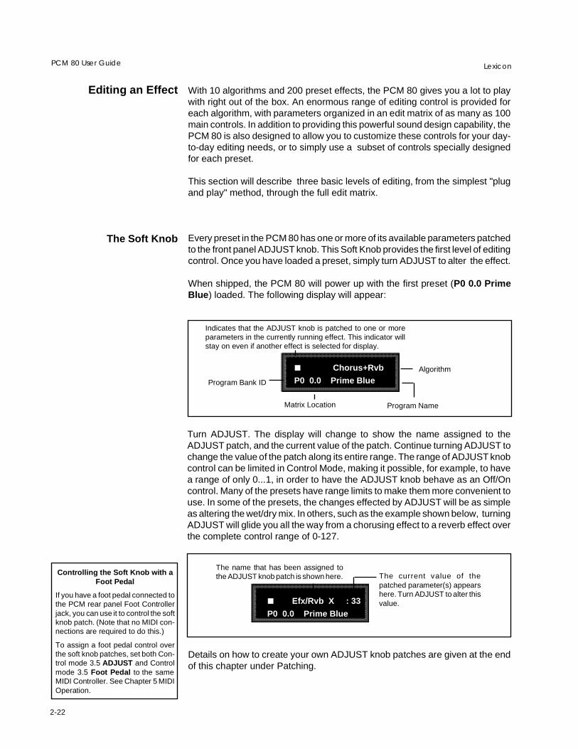
LexiconPCM 80 User Guide
2-22
Editing an Effect With 10 algorithms and 200 preset effects, the PCM 80 gives you a lot to playwith right out of the box. An enormous range of editing control is provided foreach algorithm, with parameters organized in an edit matrix of as many as 100main controls. In addition to providing this powerful sound design capability, thePCM 80 is also designed to allow you to customize these controls for your day-to-day editing needs, or to simply use a subset of controls specially designedfor each preset.
This section will describe three basic levels of editing, from the simplest "plugand play" method, through the full edit matrix.
Every preset in the PCM 80 has one or more of its available parameters patchedto the front panel ADJUST knob. This Soft Knob provides the first level of editingcontrol. Once you have loaded a preset, simply turn ADJUST to alter the effect.
When shipped, the PCM 80 will power up with the first preset (P0 0.0 PrimeBlue) loaded. The following display will appear:
The Soft Knob
Indicates that the ADJUST knob is patched to one or moreparameters in the currently running effect. This indicator willstay on even if another effect is selected for display.
Turn ADJUST. The display will change to show the name assigned to theADJUST patch, and the current value of the patch. Continue turning ADJUST tochange the value of the patch along its entire range. The range of ADJUST knobcontrol can be limited in Control Mode, making it possible, for example, to havea range of only 0...1, in order to have the ADJUST knob behave as an Off/Oncontrol. Many of the presets have range limits to make them more convenient touse. In some of the presets, the changes effected by ADJUST will be as simpleas altering the wet/dry mix. In others, such as the example shown below, turningADJUST will glide you all the way from a chorusing effect to a reverb effect overthe complete control range of 0-127.
P0 0.0 Prime Blue
Chorus+Rvb
Matrix Location
Program Bank ID
Algorithm
Program Name
P0 0.0 Prime Blue
Efx/Rvb X : 33
The name that has been assigned tothe ADJUST knob patch is shown here. The current value of the
patched parameter(s) appearshere. Turn ADJUST to alter thisvalue.
Details on how to create your own ADJUST knob patches are given at the endof this chapter under Patching.
Controlling the Soft Knob with aFoot Pedal
If you have a foot pedal connected tothe PCM rear panel Foot Controllerjack, you can use it to control the softknob patch. (Note that no MIDI con-nections are required to do this.)
To assign a foot pedal control overthe soft knob patches, set both Con-trol mode 3.5 ADJUST and Controlmode 3.5 Foot Pedal to the sameMIDI Controller. See Chapter 5 MIDIOperation.
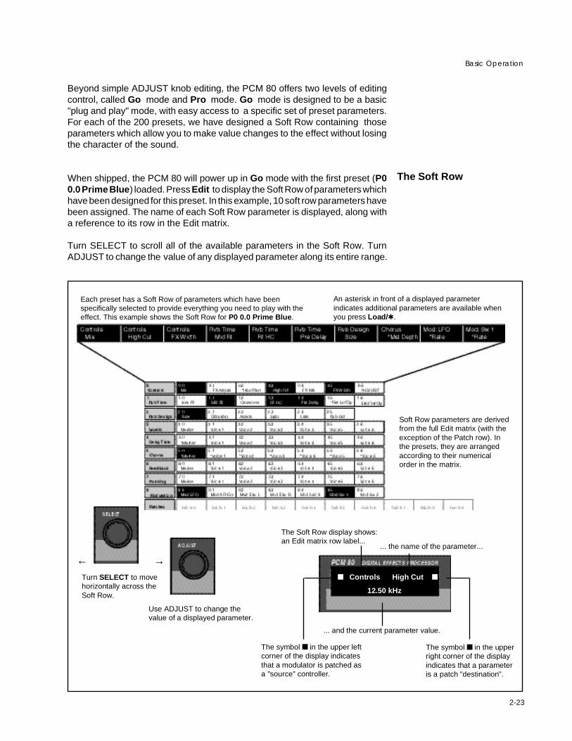
2-23
Basic Operation
Each preset has a Soft Row of parameters which have beenspecifically selected to provide everything you need to play with theeffect. This example shows the Soft Row for P0 0.0 Prime Blue.
Soft Row parameters are derivedfrom the full Edit matrix (with theexception of the Patch row). Inthe presets, they are arrangedaccording to their numericalorder in the matrix.
Beyond simple ADJUST knob editing, the PCM 80 offers two levels of editingcontrol, called Go mode and Pro mode. Go mode is designed to be a basic"plug and play" mode, with easy access to a specific set of preset parameters.For each of the 200 presets, we have designed a Soft Row containing thoseparameters which allow you to make value changes to the effect without losingthe character of the sound.
When shipped, the PCM 80 will power up in Go mode with the first preset (P00.0 Prime Blue) loaded. Press Edit to display the Soft Row of parameters whichhave been designed for this preset. In this example, 10 soft row parameters havebeen assigned. The name of each Soft Row parameter is displayed, along witha reference to its row in the Edit matrix.
Turn SELECT to scroll all of the available parameters in the Soft Row. TurnADJUST to change the value of any displayed parameter along its entire range.
The Soft Row
An asterisk in front of a displayed parameterindicates additional parameters are available whenyou press Load/.
→←Turn SELECT to movehorizontally across theSoft Row.
... the name of the parameter...
12.50 kHz
Controls High Cut
Use ADJUST to change thevalue of a displayed parameter.
The symbol in the upper leftcorner of the display indicatesthat a modulator is patched asa "source" controller.
The symbol in the upperright corner of the displayindicates that a parameteris a patch "destination".
... and the current parameter value.
The Soft Row display shows:an Edit matrix row label...
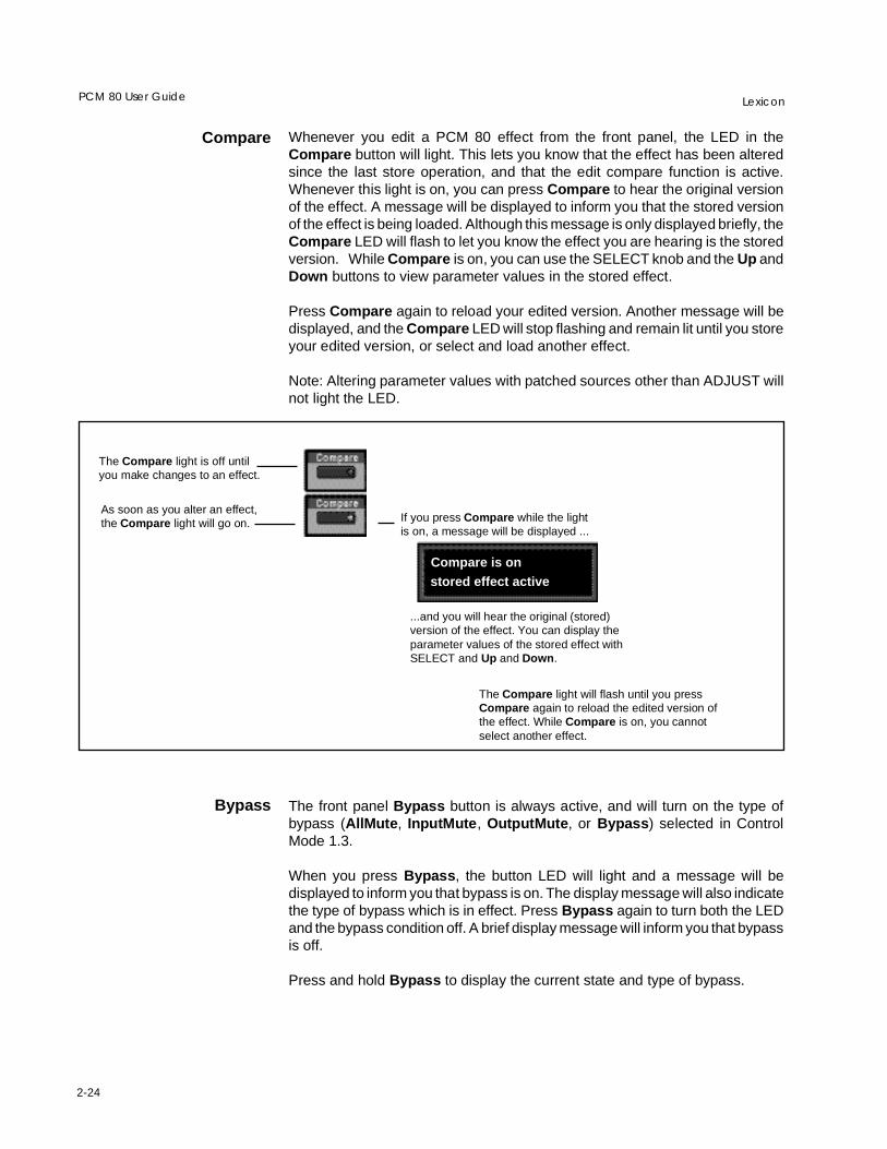
LexiconPCM 80 User Guide
2-24
Compare Whenever you edit a PCM 80 effect from the front panel, the LED in theCompare button will light. This lets you know that the effect has been alteredsince the last store operation, and that the edit compare function is active.Whenever this light is on, you can press Compare to hear the original versionof the effect. A message will be displayed to inform you that the stored versionof the effect is being loaded. Although this message is only displayed briefly, theCompare LED will flash to let you know the effect you are hearing is the storedversion. While Compare is on, you can use the SELECT knob and the Up andDown buttons to view parameter values in the stored effect.
Press Compare again to reload your edited version. Another message will bedisplayed, and the Compare LED will stop flashing and remain lit until you storeyour edited version, or select and load another effect.
Note: Altering parameter values with patched sources other than ADJUST willnot light the LED.
Bypass
If you press Compare while the lightis on, a message will be displayed ...
stored effect activeCompare is on
...and you will hear the original (stored)version of the effect. You can display theparameter values of the stored effect withSELECT and Up and Down.
As soon as you alter an effect,the Compare light will go on.
The Compare light is off untilyou make changes to an effect.
The Compare light will flash until you pressCompare again to reload the edited version ofthe effect. While Compare is on, you cannotselect another effect.
The front panel Bypass button is always active, and will turn on the type ofbypass (AllMute, InputMute, OutputMute, or Bypass) selected in ControlMode 1.3.
When you press Bypass, the button LED will light and a message will bedisplayed to inform you that bypass is on. The display message will also indicatethe type of bypass which is in effect. Press Bypass again to turn both the LEDand the bypass condition off. A brief display message will inform you that bypassis off.
Press and hold Bypass to display the current state and type of bypass.
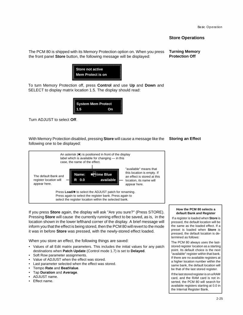
2-25
Basic Operation
Store Operations
The PCM 80 is shipped with its Memory Protection option on. When you pressthe front panel Store button, the following message will be displayed:
Mem Protect is on
Store not active
To turn Memory Protection off, press Control and use Up and Down andSELECT to display matrix location 1.5. The display should read:
1.5 On
System Mem Protect
Turn ADJUST to select Off.
With Memory Protection disabled, pressing Store will cause a message like thefollowing one to be displayed:
Turning MemoryProtection Off
How the PCM 80 selects adefault Bank and Register
If a register is loaded when Store ispressed, the default location will bethe same as the loaded effect. If apreset is loaded when Store ispressed, the default location is de-termined as follows:
The PCM 80 always uses the last-stored register location as a startingpoint. Its default choice is the next"available" register within that bank.If there are no available registers ata higher location number within thesame bank, the default location willbe that of the last stored register.
If the last stored register is on a RAMcard, and the RAM card is not in-serted, the PCM 80 will search foravailable registers starting at 0.0 inthe Internal Register Bank.
Storing an Effect
R 0.0 available
Name: Prime Blue
An asterisk () is positioned in front of the displaylabel which is available for changing — in thiscase, the name of the effect.
"available" means thatthis location is empty. Ifan effect is stored at thislocation, its name willappear here.
The default Bank andregister location willappear here.
Press Load/ to select the ADJUST patch for renaming.Press again to select the register bank. Press again toselect the register location within the selected bank.
If you press Store again, the display will ask "Are you sure?" (Press STORE).Pressing Store will cause the currently running effect to be saved, as is, in thelocation shown in the lower lefthand corner of the display. A brief message willinform you that the effect is being stored, then the PCM 80 will revert to the modeit was in before Store was pressed, with the newly-stored effect loaded.
When you store an effect, the following things are saved:• Values of all Edit matrix parameters. This includes the initial values for any patch
destinations when Patch Update (Control mode 1.7) is set to Delayed.• Soft Row parameter assignments.• Value of ADJUST when the effect was stored.• Last parameter selected when the effect was stored.• Tempo Rate and BeatValue.• Tap Duration and Average.• ADJUST name.• Effect name.
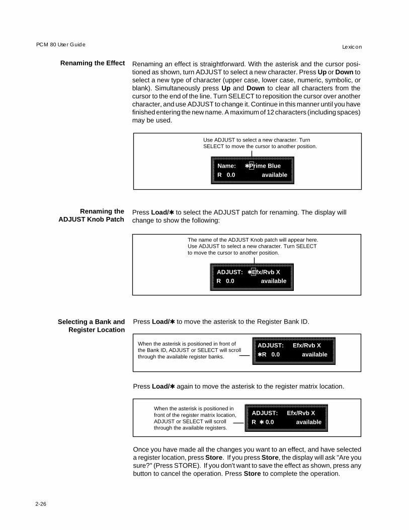
LexiconPCM 80 User Guide
2-26
Renaming the Effect
Selecting a Bank and Register Location
Press Load/ to move the asterisk to the Register Bank ID.
Renaming an effect is straightforward. With the asterisk and the cursor posi-tioned as shown, turn ADJUST to select a new character. Press Up or Down toselect a new type of character (upper case, lower case, numeric, symbolic, orblank). Simultaneously press Up and Down to clear all characters from thecursor to the end of the line. Turn SELECT to reposition the cursor over anothercharacter, and use ADJUST to change it. Continue in this manner until you havefinished entering the new name. A maximum of 12 characters (including spaces)may be used.
R 0.0 available
ADJUST: Efx/Rvb XWhen the asterisk is positioned in front ofthe Bank ID, ADJUST or SELECT will scrollthrough the available register banks.
Press Load/ again to move the asterisk to the register matrix location.
R 0.0 available
ADJUST: Efx/Rvb XWhen the asterisk is positioned infront of the register matrix location,ADJUST or SELECT will scrollthrough the available registers.
Once you have made all the changes you want to an effect, and have selecteda register location, press Store. If you press Store, the display will ask "Are yousure?" (Press STORE). If you don't want to save the effect as shown, press anybutton to cancel the operation. Press Store to complete the operation.
R 0.0 available
Name: Prime Blue
Use ADJUST to select a new character. TurnSELECT to move the cursor to another position.
Renaming theADJUST Knob Patch
R 0.0 availableADJUST: Efx/Rvb X
The name of the ADJUST Knob patch will appear here.Use ADJUST to select a new character. Turn SELECTto move the cursor to another position.
Press Load/ to select the ADJUST patch for renaming. The display willchange to show the following:

2-27
Basic Operation
Concert Hall
Plate
M-Band+Rvb
Setting Edit Mode to Pro (Control Mode 1.0) gives you access to the fullparameter matrix of the algorithm for any loaded effect whenever you press thefront panel Edit button.
To select any parameter for adjustment, use SELECT to move horizontallyacross the matrix and the Up and Down buttons to move vertically. An asterisk() appearing before a displayed parameter indicates that more than oneparameter is available at that location. Press Load/ to display these additionalparameters.
Each of the ten PCM 80 algorithms has a unique matrix, but many parametersare common to all effects, and their placement within the matrix is consistent.For example, all parameters within a given row of any matrix are related. Thistype of grouping is immediately apparent from the name of the row. For examplethe "Levels" row in any matrix will contain all of the available level controls for theeffect's delay voices.
As far as possible, rows with similar controls will always appear in the sameposition in the matrix and, within each row, parameters will generally appear inthe same position. For example, the first row (0) in every algorithm is "Controls".The Mix parameter, which is available in all effects, is always located in position0 in this row. Similarly, the last two rows of every matrix are "Modulation" andPatches". This makes it very easy to find your way around the large number ofavailable parameters, and to anticipate where to find the controls you are lookingfor when you switch between effects.
The Full Edit Matrix
Similar parameters can be found in similar positions inevery effect matrix. Once you are familiar with one editmatrix, you will find it easy to anticipate where to findcontrols in another matrix.
Detailed information about each individual edit matrix, as well as parameter andeffect descriptions are given in Chapter 3.

LexiconPCM 80 User Guide
2-28
Creating a Soft Row In Pro mode you still have complete access to the Soft Row, which appearsabove row 0 of the full edit matrix. The parameters assigned here are duplicatesof selected parameters in the matrix and can be adjusted from Row S (Soft Row),or from their matrix location.
The following example shows the edit matrix for the preset, P 0.0 Prime Blue(Chorus+Rvb algorithm). As you can see, parameters from locations throughoutthe matrix have been assigned to this Soft Row. In this preset (and in everypreset) we have designed the Soft Row by assigning the parameters innumerical order, so that parameters from the Controls row are assigned in orderto the first locations, followed by assignments from the Rvb Time row, and so on.As Soft Row parameters are also labeled with the name of the row from whichthey were taken, this makes it relatively easy to find the source parameter for anySoft Row assignment.
The Soft Row assigned to an effect appearsabove Row 0 in the full Edit matrix.
We have highlighted thoseparameters in the Edit matrixwhich have been assigned to theSoft Row of P 0.0 Prime Blue,for example: FX Width, andMod: Sw 1.
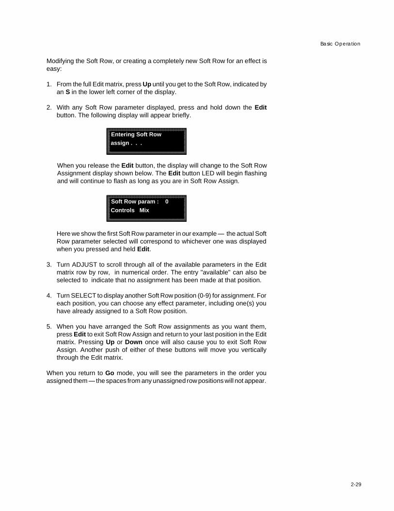
2-29
Basic Operation
When you release the Edit button, the display will change to the Soft RowAssignment display shown below. The Edit button LED will begin flashingand will continue to flash as long as you are in Soft Row Assign.
Here we show the first Soft Row parameter in our example — the actual SoftRow parameter selected will correspond to whichever one was displayedwhen you pressed and held Edit.
3. Turn ADJUST to scroll through all of the available parameters in the Editmatrix row by row, in numerical order. The entry "available" can also beselected to indicate that no assignment has been made at that position.
4. Turn SELECT to display another Soft Row position (0-9) for assignment. Foreach position, you can choose any effect parameter, including one(s) youhave already assigned to a Soft Row position.
5. When you have arranged the Soft Row assignments as you want them,press Edit to exit Soft Row Assign and return to your last position in the Editmatrix. Pressing Up or Down once will also cause you to exit Soft RowAssign. Another push of either of these buttons will move you verticallythrough the Edit matrix.
When you return to Go mode, you will see the parameters in the order youassigned them — the spaces from any unassigned row positions will not appear.
Controls Mix
Soft Row param : 0
Modifying the Soft Row, or creating a completely new Soft Row for an effect iseasy:
1. From the full Edit matrix, press Up until you get to the Soft Row, indicated byan S in the lower left corner of the display.
2. With any Soft Row parameter displayed, press and hold down the Editbutton. The following display will appear briefly.
assign . . .Entering Soft Row

LexiconPCM 80 User Guide
2-30
Patching Patching is the ability to assign a control (Source) to any PCM 80 parameter(Destination). This allows you to alter the value of the parameter by manipulatingthe control Source. For example, you can select the front panel ADJUST knobas a Source and an effect's Mix parameter as a Destination. This simple patchwill allow you to dynamically alter the mix of the effect whenever you turnADJUST. You can create as many as 10 patches, each with as many as 8 pairsof pivot points. You can patch multiple parameters to a single controller, or patchmultiple Sources to a single Destination.
All Sources are the same in the sense that each generates an output value in therange of 0-127. The output value is used to increase or decrease the setting ofa Destination parameter. Sources differ in the manner in which they generate anoutput. Some generate values continuously (they’re always “on”); some gener-ate output based on the position of a particular external MIDI controller, or anexternal footpedal, or footswitch. Some Sources generate output based onaspects of physical performance such as how loud, how fast, or how hard youplay. The PCM 80 allows you to choose from a selection of Sources as shownfor each Destination. A list of the available Sources is shown on the followingpage.
Each PCM 80 effect has an identical Patch row at the end of its Edit matrix whereyou can make as many as 10 patches.
About Sources
The Patch Row
To make a patch, use SELECT and the Down button to move down through theEdit matrix to the Patch row. A display such as the following will appear.
Pressing the Load / button will change the display to allow you to sequentiallyselect: Src, Dst, Src Value and Dst Value. Press Up or Down together withLoad / to backstep to the previous parameter.
Int LFO Patch 0 Src
SELECT will move you acrossthe Patch row (0-9).
The Source type is indicated here.(Int, MIDI or 001-119 to indicate aMIDI Controller.)
The name of the current Source assignment isshown here. (The default Source assignment isInt...Off.)
The asterisk () indicates that Sources will be selected whenyou turn ADJUST. Press Load / to change the selection toDst. Press Load / again to bring up the Values display whereyou can select Src Value and Dst Value.

2-31
Basic Operation
Assigning a SourceThree types of sources are available: Internal, MIDI and MIDI Controller. Thesetypes are indicated in the Source list by the labels: Int, MIDI, or a number (001-119). Turn ADJUST to scroll through the entire list of available sources.
LFOSineCosineSquareSawtoothPulseTriangleEnv LEnv RAR EnvLatchSw 1Sw 2Sw 1 & 2Mono LvlLeft LvlRight LvlFootpedalFoot Sw 1Foot Sw 2ADJUSTTempoOnOff
MIDI Controller NumbersInternal
(PCM 80 interprets 000 as Bank Select)001 Mod Wheel002 Breath003 Ctl 3004 Foot Ctl005 PortaTime006 Data Entry007 Volume008 Balance009 Ctl 9010 Pan011 Xpression012 Effect 1013 Effect 2014 Ctl 14015 Ctl 15016 General 1017 General 2018 General 3019 General 4020 Ctl 20... ...031 Ctl 31(PCM 80 interprets 032 as Bank Select)033 Ctl 33... ...063 Ctl 63064 Sustain065 Porta On066 Sostenuto067 SoftPedal068 Legato069 Hold 2
070 Sound Var071 Timbre072 Release073 Attack074 Bright075 Sound 6076 Sound 7077 Sound 8078 Sound 9079 Sound 10080 General 5081 General 6082 General 7083 General 8084 Porta Ctl085 Ctl 85... ...090 Ctl 90091 FX1 Depth092 FX2 Depth093 FX3 Depth094 FX4 Depth095 FX5 Depth096 Data Inc097 Data Dec098 NRPN LSB099 NRPN MSB100 RPN LSB101 RPN MSB102 Ctl 102... ...119 Ctl 119
MIDI
P BendA TouchVelocityLast NoteLow NoteHigh NoteClk Comnds
Patch Sources
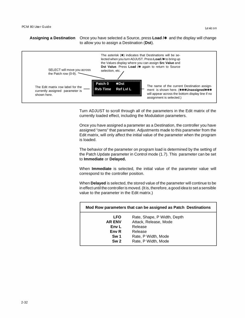
LexiconPCM 80 User Guide
2-32
Turn ADJUST to scroll through all of the parameters in the Edit matrix of thecurrently loaded effect, including the Modulation parameters.
Once you have assigned a parameter as a Destination, the controller you haveassigned “owns” that parameter. Adjustments made to this parameter from theEdit matrix, will only affect the initial value of the parameter when the programis loaded.
The behavior of the parameter on program load is determined by the setting ofthe Patch Update parameter in Control mode (1.7). This parameter can be setto Immediate or Delayed.
When Immediate is selected, the initial value of the parameter value willcorrespond to the controller position.
When Delayed is selected, the stored value of the parameter will continue to bein effect until the controller is moved. (It is, therefore, a good idea to set a sensiblevalue to the parameter in the Edit matrix.)
Assigning a Destination Once you have selected a Source, press Load / and the display will changeto allow you to assign a Destination (Dst).
Rvb Time Ref Lvl L
Patch 0 Dst
SELECT will move you acrossthe Patch row (0-9).
The name of the current Destination assign-ment is shown here. (Unassigned
will appear across the bottom display line if noassignment is selected.)
The Edit matrix row label for thecurrently assigned parameter isshown here.
The asterisk () indicates that Destinations will be se-lected when you turn ADJUST. Press Load / to bring upthe Values display where you can assign Src Value andDst Value. Press Load / again to return to Sourceselection, etc.
Mod Row parameters that can be assigned as Patch Destinations
LFO Rate, Shape, P Width, DepthAR ENV Attack, Release, Mode
Env L ReleaseEnv R ReleaseSw 1 Rate, P Width, ModeSw 2 Rate, P Width, Mode

2-33
Basic Operation
Once you have assigned a Destination, press Load / to get to the Valuesdisplay.
Assigning Values
000: Off
Patch 0 Values
Src values are shown here. The asterisk () indicatesthat this field is available for control with the ADJUSTknob (and that additional parameters are available bypressing Load /).
The current Dst value is displayed here. When you pressLoad / again, the asterisk will move to indicate that this valueis available to be changed by turning ADJUST.
000: Off Patch 0 Values
This display allows you to assign Destination values to specific Source values.These assignments are made in pairs, each with a value for the Source and avalue for the Destination. For example, the default is two pairs mapped asfollows:
minimum Src value (0) = minimum Dst valuemaximum Src value (127) = maximum Dst value
This establishes a linear relationship between the parameter and the controller.Inverse control is accomplished easily by reversing these settings. As many aseight pairs of Destination/Source values, or pivot points, can be assigned here,providing an exciting new level of dynamic control.
When creating patches, there are situations in which you will want to leave thePatch row to adjust parameters. To make this convenient, a Jump command isavailable. Jumping is dependent on the current Patch display, and is activatedsimply by pressing Edit while a certain display is active. This will jump you outof the Patch row and to the location where you can make the necessaryadjustments. Pressing Edit again will jump you back to the Patch Row. (Notethat using any front panel controls other than those required to adjust theparameter to which you have jumped, will disable the jump. This is notcatastrophic, but it will require you to return by using Up and Down andSELECT.) The following Jumps are available:
From the Patch row Src display:
• With ADJUST selected as the Source, press Edit to jump to the Controlsrow, where you can specify range limits for the ADJUST knob. Press Editagain to return to the Patch row.
• With any modulation parameter selected as a Source, press Edit to jumpto the Modulation row position of the Source. For example, if the Patchsource LFO is displayed, press Edit to jump to Modulation row position 0(LFO) where you can edit any LFO parameter value. Press Edit again toreturn to the Patch row.
Jump

LexiconPCM 80 User Guide
2-34
From the Patch row Dst selection display:
• Press Edit to jump to the Edit controls for the parameter you have selectedas the Destination. You will have complete access to all parameter controls,including any subparameters at that location. Press Edit again to return tothe Patch row.
From the Patch row Values display:
• Press Edit to jump to the next Src or Dst value. Default values are0...minimum, 127...maximum.
Jump cont'd.
Patching Examples The following examples illustrate how to create a patch, use the patch jumpfeatures, modify the default patch values and add an additional pivot point tothe example patch values.
Load program P0 0.1 EkoChorus. Press Edit to enter Edit mode, then pressUp to move to the Patch Row. Press Load/ until the display looks like this:
Creating a patch withdefault values
Int ADJUST
Patch 0 Src
Turn SELECT to select Patch 1 (which is set to Off).
Int Off
Patch 1 Src
Turning ADJUST will scroll through the entire list of available patch Sources.Turn ADJUST counterclockwise until LFO is displayed in the lower right.
Int LFO
Patch 1 Src
The LFO is now assigned as a patch Source.

2-35
Basic Operation
Patch 1 Dst Unassigned
Press Load/ to bring up patch Destinations for selection. The display shouldshow that Destination is unassigned.
The ADJUST knob will now scroll through all of the available parameters ofEkoChorus. The lower line of the display will show the edit matrix row label onthe left, and the parameters in that row on the right.
Turn ADJUST clockwise until FX Width (in the effect's Controls row) isdisplayed in the lower right corner of the display.
Patch 1 Dst
Controls FX Width
The FX Width parameter is now assigned as the patch Destination.
Now, press Load/ to bring up the Values display. This will show the defaultDestination value setting (–360 MONO). This is the value assigned to FX Widthwhen the LFO is at its minimum value (000).
Patch 1 Values 000 –360 MONO
Turn ADJUST one click counterclockwise to display the default Destinationvalue (+360 MONO) assigned to FX Width when the LFO is at its maximum value(127).
Patch 1 Values
127 +360 MONO
That’s all there is to setting up a default patch— select a Source and Destination,and the minimum and maximum patch values are set automatically.
Of course, you will often want to modify the patch further, either by adjusting themodulation source parameters, changing the default values or adding additionalpivot points. In the following sections, we’ll continue using this patch todemonstrate examples of these modifications. When we’re done, the new patchwill add dynamic spatialization to the EkoChorus program.

LexiconPCM 80 User Guide
2-36
Continuing the previous example, we’ll adjust the rate of the LFO by jumping toit from the Patch row.
Press Load/ repeatedly to return to the Patch 1 Source selection display.
Adjusting the modulationsource parameters
Int LFO
Patch 1 Src
Mod : LFO Rate
8.0 0.21 Hz
The display now shows position 8.0 in the Edit matrix Mod Row. The smallsquare in the upper left corner of the display is a patch source indicator. Thisindicator appears whenever a modulator (such as the LFO in this example) hasbeen assigned as a patch Source in the effect being edited.
Turn ADJUST to change the LFO rate to 0.10Hz.
Press Edit to jump directly to the LFO parameters in the Mod row.
The asterisk () indicates that LFO Rate will be altered whenyou turn ADJUST. Press Load / to change the selection tothe other LFO parameters ( Shape, P Width and Depth).
Patch Source Indicator
Mod : LFO Rate
8.0 0.10 Hz
Now, press Edit to jump back to your previous position in the Patch row.
Int LFO
Patch 1 Src

2-37
Basic Operation
Let’s modify the patch further by adjusting the Destination values to a moreuseful range.
Press Load/ repeatedly until the Patch 1 Values screen is displayed.
Changing the defaultdestination values
Patch 1 Values 000 –360 MONO
Notice that the is to the left of the Source value. This indicates that the Sourcevalue is selected and its value will be changed when you turn ADJUST.
Press Load/ once to move the to the right of the Source value. When the is in this position, ADJUST will change the Destination value.
Patch 1 Values
000 : –360 MONO
Patch 1 Values
000 –360 MONO
Press Load / to move the asterisk to this position,where it indicates that Destination values will bealtered when you turn ADJUST.
The asterisk () indicates that the Source valuewill be altered when you turn ADJUST.
With the Destination value selected, turn ADJUST clockwise to set the value to+0.
Patch 1 Values000 : +0 MONO
Next, we’ll want to adjust the Destination value when the LFO is at its maximumvalue. One way to do this is to press Load/ three times to cycle the to thedisplay of the Source value, and continue on from there — but we’ve provideda short cut! Press Edit to jump to the next assigned value ( in our example, theLFO maximum value).
Patch 1 Values
127 : +360 MONO
Now our example has been modified so that the LFO sweeps the FX Width Valuefrom 0 to 90. This creates a dynamic alteration of the effect’s spatial character-istics. Its stereo image changes smoothly from mono to stereo, to surround, andback again.
Note that the remains in the same position, so you can just turn ADJUST toset the new Destination value. Set the value to +90.
Patch 1 Values127 : +90 L-R, R-L

LexiconPCM 80 User Guide
2-38
So far, our example uses only two pairs of patch values. The Destinationparameter moves linearly between the value assigned at 000 and the valueasssigned at 127.
You can watch this change by displaying the Destination parameter. Here’s howto jump directly to it from the patch:
Press Load/ repeatedly to return to the Patch 1 Destination selection display.
Adding an additional pivotpoint to the patch
Controls FX Width
Patch 1 Dst
Press Edit to jump directly to the FX Width parameter in the Controls Row.
Controls FX Width
0.5 +0...90 MONO
Patch Destination Indicator
The FX Width value will be changingfrom 0 to 90 and back again.
The display will change to show position 0.5 in the Controls Row. Note that thevalue is changing continuously from 0 to 90 and back again. Notice also the smallsquare in the upper right corner of the display. This patch destination indicatorappears whenever a parameter has been assigned as a patch Destination in theeffect being edited.
Now let’s return to the Patch row to add a pivot point to the effect.
Press Edit to jump back to the Patch row.
Controls FX Width
Patch 1 Dst

2-39
Basic Operation
Press Load/ to bring up the Values display. The last value edited will bedisplayed, so you will see either the minimum or maximum value.
Patch 1 Values127 : +90 L-R, R-L
Patch 1 Values 000 +0 MONO OR
By adding this pivot point, we have put a “kink” in the patch. The value of theDestination parameter no longer moves in a straight line between 0 and 90.Instead it moves from 0 to –45, and then from –45 to 90. This will produce a verydifferent sounding spatial change from the original patch. You can see thedifference by pressing Load/ twice to display the patch Destination, thenpressing Edit to jump back to the Destination parameter to watch its valuechange.
If the is not at the left of the Source value, press Load/ three times to moveit there. (You can take a short cut instead — simultaneously press Down andLoad/ to back-step.)
Patch 1 Values
127 : +90 L-R, R-L
Patch 1 Values
000 +0 MONO OR
Turn ADJUST to display 64. This will be the Source value of our new pivot point.The string of dots in the destination value portion of the display indicate that thereis no Destination value assigned when the source value is 64.
Patch 1 Values
064 : . . . . . . . . . . . . . .
Press Load/ to move the to the right of the Source value, and turn ADJUSTclockwise to set the Destination value for this point to –45.
Patch 1 Values064 : -45 R, L
LexiconPCM 80 User Guide
2-40
If you create two or more patches with the same Destination, the Destinationvalue will be the sum of all of the patches assigned to it.
For example, if Pedal and ADJUST are both assigned to Mix, the Mix value willbe the sum of the patch Destination values for those two patches. When creatingmultiple patches to the same Destination, you should set the individual Destina-tions to values which, when added together, are less than or equal to themaximum value for the parameter. Pedal and ADJUST, for example, could eachhave a maximum value of 50%, or they could be assigned values of 25% and75%, 60% and 40%, etc.
When the sum of multiple patched parameter Destination values is greater thanthe maximum value of the parameter, the parameter value will remain atmaximum until the sum of the patches falls below it.
AR ENV, Latch, Sw 1 and Sw 2 are each activated by assigning a thresholdsource to T Src that is used to turn them on and off. This assignment is asubparameter in the Mod row — not in the Patch row.
For an example, check out ADJUST and Latch in the preset P0 3.1 RotorCabinet.
Multiple Patches with theSame Destination
Mod Row Patches
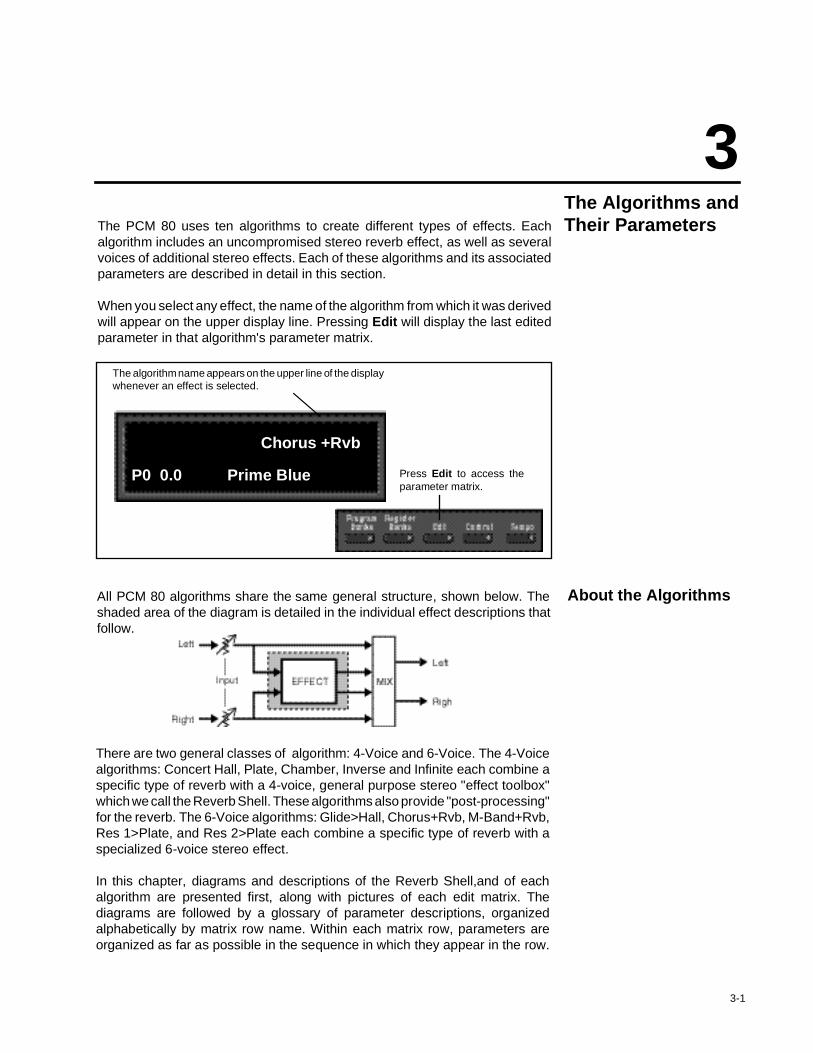
3-1
The Algorithms and Their Parameters
3The Algorithms andTheir Parameters
There are two general classes of algorithm: 4-Voice and 6-Voice. The 4-Voicealgorithms: Concert Hall, Plate, Chamber, Inverse and Infinite each combine aspecific type of reverb with a 4-voice, general purpose stereo "effect toolbox"which we call the Reverb Shell. These algorithms also provide "post-processing"for the reverb. The 6-Voice algorithms: Glide>Hall, Chorus+Rvb, M-Band+Rvb,Res 1>Plate, and Res 2>Plate each combine a specific type of reverb with aspecialized 6-voice stereo effect.
In this chapter, diagrams and descriptions of the Reverb Shell,and of eachalgorithm are presented first, along with pictures of each edit matrix. Thediagrams are followed by a glossary of parameter descriptions, organizedalphabetically by matrix row name. Within each matrix row, parameters areorganized as far as possible in the sequence in which they appear in the row.
All PCM 80 algorithms share the same general structure, shown below. Theshaded area of the diagram is detailed in the individual effect descriptions thatfollow.
About the Algorithms
The PCM 80 uses ten algorithms to create different types of effects. Eachalgorithm includes an uncompromised stereo reverb effect, as well as severalvoices of additional stereo effects. Each of these algorithms and its associatedparameters are described in detail in this section.
When you select any effect, the name of the algorithm from which it was derivedwill appear on the upper display line. Pressing Edit will display the last editedparameter in that algorithm's parameter matrix.
The algorithm name appears on the upper line of the displaywhenever an effect is selected.
Chorus +Rvb
Press Edit to access theparameter matrix.
P0 0.0 Prime Blue

Lexicon
3-2
PCM 80 User Guide
The 4-VoiceAlgorithms
The Reverb Shell Each of the 4-Voice algorithms share a common set of controls and parametersbuilt around one of five stereo reverb effects: Concert Hall, Plate, Chamber, Inverse and Infinite. The diagram below shows these common controls and parameters as they are structured around a reverb effect. We call this structure the Reverb Shell. (Individual reverb effects are described on the following pages.)
In the 4-Voice algorithms, input levels and pans determine the signal flow to left and right pairs of delay voices, and also to the reverb effect. Each delay voice has individually adjustable level, delay, feedback, and pan controls, as well as Host controls for all of the voices. These algorithms can be used to create a wide variety of stereo delay and modulation effects in parallel with studio quality stereo reverberation.
The two delays after the reverb effect are referred to as post delays. The PstDly Mix control determines how much post delay is actually heard. The Rvb Width control affects only the output of the reverb portion of the effect.
The delays and the output of the reverb effect are summed at the FX Mix control. This control allows you to blend the relative amounts of delay and reverb.
FX Width controls the spatial characteristics of the composite reverb and delay effect.
The Hi-Cut parameter provides high end rolloff, while FX Adjust determines the output volume of the entire processed signal.
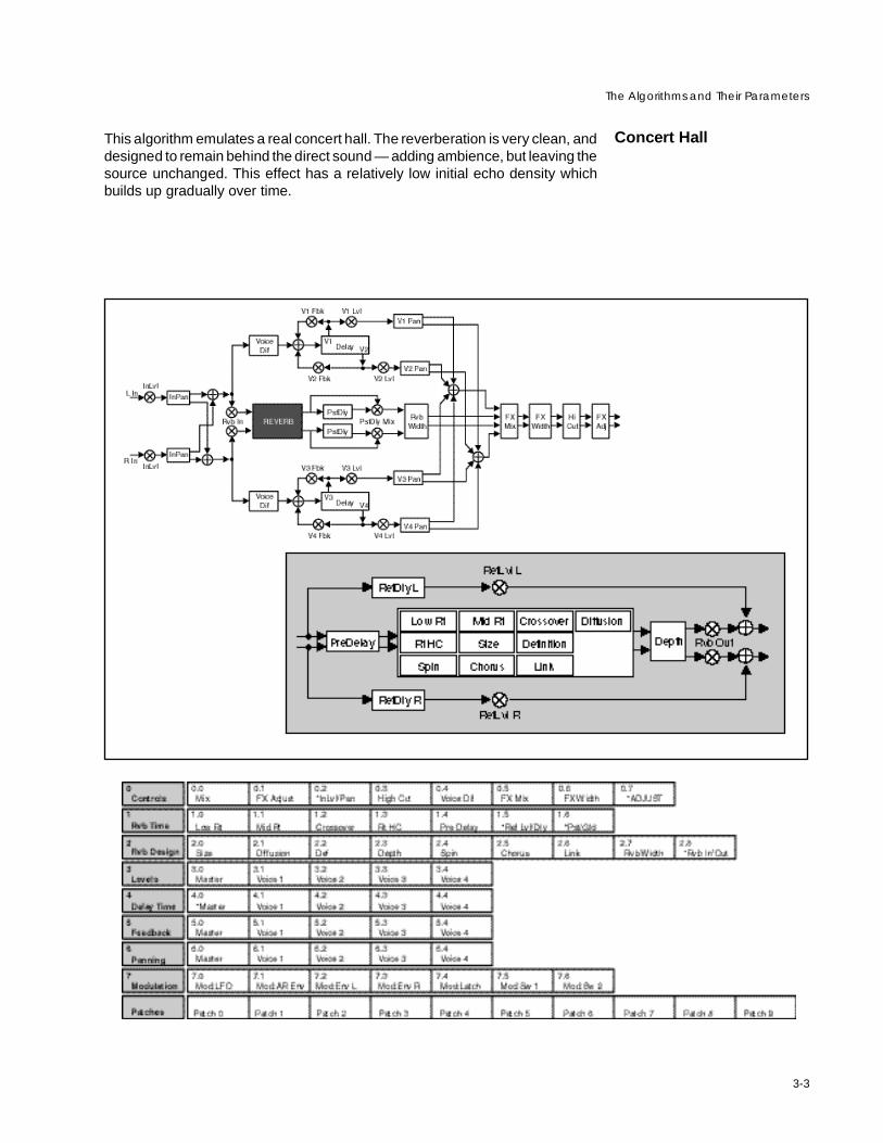
3-3
The Algorithms and Their Parameters
This algorithm emulates a real concert hall. The reverberation is very clean, anddesigned to remain behind the direct sound — adding ambience, but leaving thesource unchanged. This effect has a relatively low initial echo density whichbuilds up gradually over time.
Concert Hall

Lexicon
3-4
PCM 80 User Guide
The Plate algorithm mimics the sound of metal plates, with high initial diffusionand a relatively bright sound. This makes them a good choice for enhancing anytype of percussion.
Plate

3-5
The Algorithms and Their Parameters
The Chamber algorithm produces an even, relatively dimensionless reverbera-tion, with little change in color as the sound decays. The initial diffusion is similarto the Concert Hall algorithm, but the sense of space and size is much lessobvious. This characteristic, along with the low color in the decay tail makesChamber useful on a wide range of material. It is especially useful on spokenvoice, giving a noticeable increase in loudness with very low color.
Chamber

Lexicon
3-6
PCM 80 User Guide
Inverse The Inverse algorithm allows you to vary the slope of the initial portion of thereverb envelope. The slope can decay, remain level, or rise over a variable timeinterval. When the time interval is up, the reverberation cuts off abruptly. Theresulting effect is similar to a gate, but is not at all dependent on the level orcomplexity of the input signal. Slopes are adjustable over a negative, even, orpositive slope. Positive slopes create inverse effects, while more even slopescreate gated effects. Negative slope values have rather natural reverb tails.

3-7
The Algorithms and Their Parameters
InfiniteInfinite is acoustically similar to the Chamber algorithm, with the addition of anInfinite parameter. When this parameter is turned on, the input to the reverberatorramps off. (Note that this still allows the Reverb Shell to be utilized.) With Infiniteon, the reverb tail remains constant, creating strange and useful reverb effects.When Infinite is switched off, input to the reverberator is restored, and the currentrunning reverb time is utilized.
Lexicon
3-8
PCM 80 User Guide
The 6-VoiceAlgorithms
Each 6-Voice algorithm is a combination of a specific 6-voice stereo effect anda specific reverb effect. These algorithms: Glide>Hall, Chorus+Rvb, M-Band+Rvb,Res1>Plate and Res2>Plate are each optimized for a particular class of audioprocessing effects in combination with studio quality stereo reverberation,bringing formidable processing power and flexibility to effects creation.
The 6-Voice algorithms use the same, uncompromised, stereo reverberationeffects as the 4-Voice algorithms but, instead of the general-purpose ReverbShell, each reverb is coupled with a unique 6-voice stereo effect: gliding delays,6-voice chorus, multi-band EQ, and two 6-voice resonators. Voices 1-3 areconnected to input audio panned to the left. Voices 4-6 are connected to inputaudio panned to the right. (Use the InPan L and InPan R controls at Controlmode 0.2 to pan input audio.) Each voice has independent delay time, panningand level controls, in addition to other parameters specific to the particular effect.
In the Glide>Hall, Res1>Plate and Res2>Plate algorithms, the reverb effect isin series with the 6-voice effect. Use FX Mix to set the relative level of dry andreverberated effect.
In the M-Band+Rvb and the Chorus+Rvb algorithms, the reverb effect is inparallel with the 6-voice effect. Use FX Mix to set the balance of the 6-voice effectand the reverb.

3-9
The Algorithms and Their Parameters
A stereo pair of 2-tap gliding delays feeds six individually adjustable delayvoices. Each voice has its own level, feedback, delay, cross-feedback, and panparameters. The output of these delay voices is fed into a Concert Hall reverbalgorithm. Glide>Hall is useful for creating such effects as stereo flangers, loopsamplers, pitch modulation, etc. which can then be fed into the reverb.
This algorithm can address up to 4 Meg of delay memory (with optional SIMMsadded to the PCM 80), providing 42 seconds of stereo delay.
Glide>Hall

Lexicon
3-10
PCM 80 User Guide
The Chorus effect has six separately adjustable voices — allowing the PCM 80to sound like a rack of six digital delay boxes. Each voice has its ownindependently adjustable chorus depth and rate, level control, delay time,feedback and panning control. The 6-voice chorus is in parallel with a platealgorithm, providing two independent stereo effects.
Note that the Diffusion parameter (Rvb Design 2.1) is shared by both the reverband the chorus effect.
Chorus+Rvb

3-11
The Algorithms and Their Parameters
Chorus+Rvb cont'd.

Lexicon
3-12
PCM 80 User Guide
This effect features six separately adjustable voices, each with its own levelcontrol, delay time, low and high frequency filters, feedback and pan controls.The multi-band effect is in parallel with a Chamber effect, providing independentstereo effects. Note that the Diffusion parameter (Rvb Design 2.1) is shared byboth the multi-band and reverb effects. Note also that, in this particular algorithm,the diffuser is within the feedback paths of the multi-band voices. This allows youto create filtered echoes that grow more diffuse with each repeat, or to createeffects with filtered echoes passing through the reverberator.
This algorithm can address up to 4 Meg of delay memory (with optional SIMMsadded to the PCM 80), providing 42 seconds of stereo delay.
M-Band+Rvb

3-13
The Algorithms and Their Parameters
M-Band+Rvb cont'd.

Lexicon
3-14
PCM 80 User Guide
The Resonant Chord effects use impulsive energy at the inputs to excite sixresonant voices (notes). The level, pitch, duration, and high-frequency cutoff ofthe overtones for each voice are separately controllable. Each voice can bepanned independently. The voices resonate to some degree with any input, butthe most effective excitation contains all frequencies, like percussion. Otherinstruments may give a quality of tonal ambience in which certain notes riseethereally from the background. The output of the resonator is then fed into astereo plate reverb effect.
The two algorithms differ in the way pitches are assigned to the resonators. InRes1>Plate, pitches are assigned to the six voices chromatically, in a round-robin. If, for example, MIDI note numbers are used to assign pitch, theresonators will constantly be re-tuned to the pitches of the last six MIDI notesreceived. (This can produce an effect similar to playing a piano with the sustainpedal depressed.) In Res2>Plate, pitches are assigned to the six resonatorsdiatonically — harmonized with the key, scale, and root of your choice. If MIDInote numbers are used to assign pitch, the resonators will constantly be re-tunedto harmonize with the incoming notes.
These algorithms can address up to 4 Meg of delay memory (with optionalSIMMs added to the PCM 80), providing 38 seconds of stereo delay.
The Resonant ChordAlgorithms:
Res1>Plate andRes2>Plate

3-15
The Algorithms and Their Parameters
Res2>Plate
The Resonant ChordAlgorithms:Res1>Plate andRes2>Plate cont'd.
Res1>Plate

Lexicon
3-16
PCM 80 User Guide
The Parameters PCM 80 parameters are organized into labeled rows within each edit matrix.Although there are similarities among all matrixes, such as having a row ofControls first, and Modulation and Patching rows last, some of the parameterswithin each row, and some entire rows are unique to specific algorithms.
This section contains descriptions for all PCM 80 parameters, organizedalphabetically by row label as follows:
ChorusControlsDelay TimeFeedback/Cross-FeedbackFiltersGlide FXLevelsModulationPanningPatchingPitchResonanceRvb DesignRvb Time
Individual parameter descriptions within each row are presented, as far as possible, in the order in which they appear from left to right in the edit matrix.
In the Chorus+Rvb algorithm, Row 5 provides parameters which provide rate and depth controls for each of the six chorus voices, as well as Host rate and depth controls.
MstDepth and MstRateTwo Host Chorus parameters in the first row position allow Chorus, Depth and Rate for all voices to be simultaneously scaled. Each control has a range of 0-200%. Press Load/ to toggle between MstDepth and MstRate.
Voices (Depth and Rate)Each voice position has Depth and Rate controls to set the time range (delay) and rate of change across that time range (pitch) of the chorusing effect. (Press Load/ to toggle between them.) Depth provides settings of 0-500ms in single millisecond increments. Rate parameter can be set to 0Hz (Off), or to one of one-hundred selections from 0.01-3.50Hz. Depths of 10-30ms combined with Rates as high as 0.50Hz provide subtle chorusing and multivoicing effects. Depths of hundreds of milliseconds combined with higher Rates provide a wide range of pitch shifting effects.
Chorus
3-17
The Algorithms and Their Parameters
Row 0 of every algorithm contains parameters that provide overall control ofboth the reverb and voice effects.
MixMix controls the ratio of dry and wet signal present at the PCM 80 outputs. Whenthe PCM 80 is patched into a console or an instrument amplifier through anauxiliary or effects loop, this control should always be set to 100% wet. (ControlMode 1.1 allows you to select a global Mix setting.) When an instrument isplugged directly into the PCM 80, a setting between 45 and 65% is a goodstarting point.
FX AdjustFX Adjust controls the level of the processed (wet) signal before it is mixed withthe dry signal (if any) and sent to the audio outputs. The range of this parameteris +12dB to -73dB, and Off (wet output muted.) FX Adjust is inactive when thePCM 80 is in Bypass mode, so it is a good idea to compare the levels with Bypasson and off while editing this parameter. Adjust it until the audio level sounds thesame with bypass on and off.
InLvl L&R, InPan L&RInLvl L and InLvl R control the level and phase of the unprocessed dry signal intothe effects. The range of these parameters is from Full (0dB) Phase Normal, to-85dB Phase Normal, Off, -85dB Phase Inverted to Full (0dB) Phase Inverted.
InPan L and InPan R control the location of the left and right input audio as astereo image to the effect's audio input. Unmodified stereo imaging to the effectscan be achieved by setting InPan L hard left (50L) and InPan R hard right (50R).Changing InPanL to any other value (49L to 50R), takes the left audio input andpresents it as a panned source to the effect's left and right input. Changing InPanR to any value other than 50R, does the same for the right audio input.
High CutHigh Cut sets the high frequency cutoff of a low-pass filter. This parameteraffects both channels.
Voice DifThis parameter is available in all of the 4-Voice Algorithms, and in Glide>Hall.It controls the density of echoes in the delay voices, independently of Reverbdiffusion. High levels of diffusion thicken, or smear, the echoes. This is mostnoticeable on material with sharp transients.
FX MixFX Mix controls the balance of reverb and non-reverb effects. (Non-reverbeffects are those processed as "voices" controlled by level, delay and feedbackparameters generally found in rows 3-7.) The range of this control is 0 to 100%.
Controls

Lexicon
3-18
PCM 80 User Guide
FX WidthFX Width can be thought of as an extension of typical mono to stereo imagingcontrols. The range of this parameter is -360 to +360, in single digit increments.Values of -360, 0, or +360 cause the effect's audio output to be mono. Valuesof -315 and +45 cause the output to be normal left/right stereo. Values of -45 and+315 cause "swapped", or right/left stereo.
Value Display Label Description
360 MONO Phase Normal Mono315 R, L Phase Normal R/L stereo270 R–L, L–R R–L, L–R surround225 STEREO INV Phase Inverted L/R Stereo180 MONO INV Phase Inverted Mono135 R, L INV Phase Inverted R/L Stereo90 L–R, R–L L–R, R–L surround45 STEREO Phase Normal L/R stereo
0 MONO Phase Normal Mono-45 R,L Phase Normal R/L Stereo-90 R–L, L–R Phase Inverted R–L, L–R surround
-135 STEREO INV Phase Inverted L/R Stereo-180 MONO INV Phase Inverted Mono-225 R, L INV Phase Inverted R/L Stereo-270 L–R, R–L L–R, R–L surround-315 STEREO Phase Normal L/R Stereo-360 MONO Phase Normal Mono
The large and duplicated range of this parameter allows smooth glides from anyLeft/Right Mix, Phase, Mono/Stereo image point to any other. These are on theoutput of the FX Mix. Of particular interest are: 0 MONO, 45 STEREO, and 90L–R, R–L (surround channel). This parameter can be changed in real-time forfascinating spatial effects.
ADJUSTThis control allows you to specify the range of control of the ADJUST knob whenit is patched to a parameter. Low and High settings are available, allowing youto select full range (0-127) for those parameters where it is appropriate and tolimit the range in other cases. You can, for example set the Low value to 0, andthe High value to 1, to have ADJUST behave as an on/off control. Many of thepresets take advantage of this, and have ADJUST range limits which areappropriate to the specific parameter.
Controls cont'd.

3-19
The Algorithms and Their Parameters
In each algorithm, the Delay Time row contains parameters for delay settings of each voice, as well as Host delay parameters for all voices.
Host, GldResp, GldRange, ClearPress Load/ to cycle through selections: Host, GldResp, GldRange and Clear.
HostThis control allows you to simultaneously change the delay times of all voices in the effect. The available range is from 0-200%. This provides a simple way to expand or close in all of the voice delay times. If a voice's delay time is set to 500ms, changing the setting of the Host parameter to 200% will change the delay time to 1000ms. Setting this parameter to 0% is an easy way to set all the delays to 0 from a single control.
GldRespIn all of the 4-Voice algorithms, and in the Chorus+Rvb algorithm, this parameter controls the response of the glide. The range is 0-100, with a typical default setting of 50. This setting provides a good, real-time glide. Changing a delay time from 0 to 100ms with a glide response of 0, causes the glide delays to take a minute or more, allowing subtle changes in delay times and echoes with no noticeable pitch shifting. A glide response of 100 is ultrafast, causing high speed pitch shift, and even chirping effects with large delay time changes.
GldRangeIn all of the 4-Voice algorithms, and in the Chorus+Rvb algorithm, this parameter controls the range over which changes to the voice delay time will be performed as a glide. For example, if GldRange is set to 100ms, and the PstDly L and R times are varied over a range of 100ms, those delays will glide smoothly from one delay time to another. Suddenly changing the delay time to a greater value, such as 200ms, will cause the audio delay to change instantly to the new time without gliding. The available range is 0-1.365sec, with 0 causing all delay time changes to be "instantaneous", and 1.365 causing all delay time changes to glide.
ClearThis is an On/Off control which allows you to instantly clear all of the audio in the delay voices. A typical use for this control might be to patch it to a footswitch to allow one tap removal of all old audio from the delays to start fresh. While Clear is on, no new audio will pass through any delay voice set above 1ms.
Delay Time
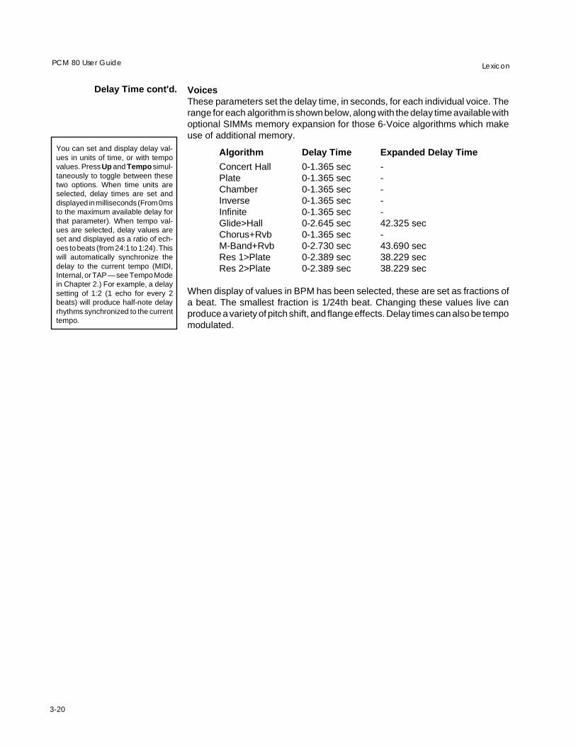
Lexicon
3-20
PCM 80 User Guide
VoicesThese parameters set the delay time, in seconds, for each individual voice. Therange for each algorithm is shown below, along with the delay time available withoptional SIMMs memory expansion for those 6-Voice algorithms which makeuse of additional memory.
Algorithm Delay Time Expanded Delay Time
Concert Hall 0-1.365 sec -Plate 0-1.365 sec -Chamber 0-1.365 sec -Inverse 0-1.365 sec -Infinite 0-1.365 sec -Glide>Hall 0-2.645 sec 42.325 secChorus+Rvb 0-1.365 sec -M-Band+Rvb 0-2.730 sec 43.690 secRes 1>Plate 0-2.389 sec 38.229 secRes 2>Plate 0-2.389 sec 38.229 sec
When display of values in BPM has been selected, these are set as fractions ofa beat. The smallest fraction is 1/24th beat. Changing these values live canproduce a variety of pitch shift, and flange effects. Delay times can also be tempomodulated.
Delay Time cont'd.
You can set and display delay val-ues in units of time, or with tempovalues. Press Up and Tempo simul-taneously to toggle between thesetwo options. When time units areselected, delay times are set anddisplayed in milliseconds (From 0msto the maximum available delay forthat parameter). When tempo val-ues are selected, delay values areset and displayed as a ratio of ech-oes to beats (from 24:1 to 1:24). Thiswill automatically synchronize thedelay to the current tempo (MIDI,Internal, or TAP — see Tempo Modein Chapter 2.) For example, a delaysetting of 1:2 (1 echo for every 2beats) will produce half-note delayrhythms synchronized to the currenttempo.

3-21
The Algorithms and Their Parameters
Parameters in this row provide level and phase setting for feedback of individual voices, as well as a Host feedback parameter for all voices. In the Glide>Hall algorithm, a duplicate set of parameters is included for cross-feedback.
HostA Host Feedback control is available in effects which have a feedback level control for each voice. It allows the feedback level for all voices to be simulta-neously adjusted over a range of 0-100%.
VoicesIn the 4-Voice algorithms, four voice controls are provided for adjustment of the level and polarity of signals recirculated back to the input of individual voices. Note that, as Voices 1 and 2 and Voices 3 and 4 are paired, caution should be observed not to create feedback within a pair which exceeds more than 100%.
In the Chorus+Rvb and the M-Band+Rvb algorithms, six voice parameters control the feedback level of the voice delays. Voices 1, 2, and 3 Fbk control the individual voice feedback levels from the left channel voice delay outputs to the left channel delay feedback input. Voices 4, 5, and 6 Fbk control the individual voice feedback levels from the right channel voice delay outputs to the right channel delay feedback input.
The range of these parameters is from +100% down to 1% (Phase Normal feedback), 0% (Off), –1% up to –100% (Phase Inverted feedback).
In the Glide>Hall algorithm, the Feedback row provides both Feedback and Cross Feedback parameters as described below. Press Load/ at each row position to toggle between Feedback and Cross Feedback parameters.
hst Fbk, hst X-FbkThese parameters allow the feedback and cross feedback levels for all voices to be simultaneously scaled over a range of 0-100%.
Voices 1-6 Fbk, X-FbkThese parameters control the feedback and cross feedback levels and the polarity of the voice delays.
Voices 1, 2, and 3 Fbk control the individual voice feedback levels from the left channel voice delay outputs to the left channel delay feedback input.
Voices 1, 2, and 3 X-Fbk control the individual voice feedback levels from the left channel voice delay outputs to the right channel delay feedback input.
Voices 4, 5, and 6 Fbk control the individual voice feedback levels from the right channel voice delay outputs to the right channel delay feedback input.
Voices 4, 5, and 6 X-Fbk control the individual voice feedback levels from the right channel voice delay outputs to the left channel delay feedback input. The range of these parameters is from +100% down to 1% (Phase Normal feed-back), 0% (off), –1% up to –100% (Phase Inverted feedback).
The sum of all Fbk and X-Fbk values for each channel should be less than 100%.
Feedback/Cross Feedback
Lexicon
3-22
PCM 80 User Guide
In the M-Band+Rvb algorithm, Row 5 contains parameters for cut-off frequen-cies of low and high cut filters for each voice, as well as Host low and high cut controls for all voices.
hst LC/HCTwo Host controls are provided in the first row position. Press Load/ to toggle between them. The High Cut Host allows simultaneous adjustment of the high frequency cut-off points for the filters on all voices in single semitone increments up or down from the individual voice settings. The Low Cut Host allows simultaneous adjustment of the low frequency cut off points for the filters on all voices in single semitone increments up or down from the individual voice settings.
V1-V6 LoCut and HiCutThe low cut and high cut filters operate at 12dB/octave. There are individual low cut and high cut filters for each of six voices. The ranges of the filter cut-off points are from 20-20,000Hz at approximately semitone intervals across the entire range for a total of 121 cut off points. The low cut filters have an OFF position just below 20Hz. The high cut filters have an OFF position just above 20,000Hz.
In the Glide>Hall algorithm, Row 3 contains level, delay and feedback param-eters for a pair of stereo gliding delays that precede the 6-voice delay.
Gld LvlGld Lvl controls the stereo output level from all gliding delays (A, B, Left and Right). It has a range of Full (0dB) down to -85dB and Off.
A Left (A Lvl L and A Dly L)These parameters control the output level and delay time of the left channel A Glide Delay. A Lvl L has a range of Full (+0dB), Phase Normal down to -85dB, Phase Normal, OFF, -85dB Phase Inverted up to Full (+0dB), Phase Inverted. A Dly L has a range of 0.0 milliseconds to 42.0 milliseconds in 0.1 millisecond units.
A Right (A Lvl R and A Dly R)These parameters control the output level and delay time of the right channel A Glide Delay. They have the same ranges as A Left.
B Left (B Lvl L and B Dly L)These parameters control the output level and delay time of the left channel B Glide Delay. They have the same ranges as A Left.
B Right (B Lvl R and B Dly R)These parameters control the output level and delay time of the right channel B Glide Delay. They have the same ranges as A Left.
Fbk L/RThese parameters control the feedback levels of the corresponding left and right channel Glide Delays. The range of these parameters is from +100% down to 1% (Phase Normal feedback), 0% (off), -1% up to –100% (Phase Inverted feedback).
Filters
Glide FX

3-23
The Algorithms and Their Parameters
X-Fbk L/RThese parameters control the corresponding cross feedback levels of the left and right channel glide delays. Specifically, X-Fbk L controls the feedback from the left channel A+B glide delay output to the right channel glide delay feedback input. X-Fbk R controls the feedback from the right channel A+B glide delay output to the left channel glide delay feedback input. The range of these parameters is from +100% down to 1% (Phase Normal feedback), 0% (off), -1%up to –100% (Phase Inverted feedback).
In each algorithm, the Levels row contains parameters for the phase and level of each voice, as well as a Host level parameter for all voices.
HostThe Host Level controls the overall level in effects which have more than one voice. This permits simultaneous changes in all voice levels without altering the balance between individual voices.
In the Res1>Plate and Res2>Plate algorithms, the Host parameter contains two Host parameters for the six resonator voices: hst Lvl and hst Fbk.(Load/ will toggle between them.) hst Lvl is a Host level control for all of the resonator voices, as described above. Use care when adjusting this value. The resonators will put out high levels if the input source has any components that are close in pitch to the resonator tunings. In general, this control should be set to 0dB or less.
The hst Fbk control allows the feedback levels for all voices to be scaled over a range of 0-100%.
VoicesIndividual controls are provided for each Voice Level. Voices can be turned completely off, full on, or set to any point between, in 1dB increments. There are as many voice level controls as there are voices in an effect.
In the Res1>Plate and Res2>Plate algorithms, positions 1-6 contain both level and feedback parameters for each of the six resonator voices. (Load/ will toggle between them.) Lvl controls the individual level and polarity for each voice. Voices can be turned completely off, full on, or set to any point in between in 1dB increments. Use care when adjusting this value. The resonators will put out high levels if the input source has any components that are close in pitch to the resonator tunings. In general, this control should be set to a value less than Full.
The Fbk controls set the feedback level and polarity of each voice. Voices 1-3 Fbk control the feedback levels from the left channel delay voice outputs to the left channel delay voice inputs. Voices 4-6 Fbk control the feedback levels from the right channel delay voice outputs to the right channel delay voice inputs. The sum of the values for either side should be less than 100%. (Disregard the negative sign when adding values.)
Glide FX cont'd.
Levels
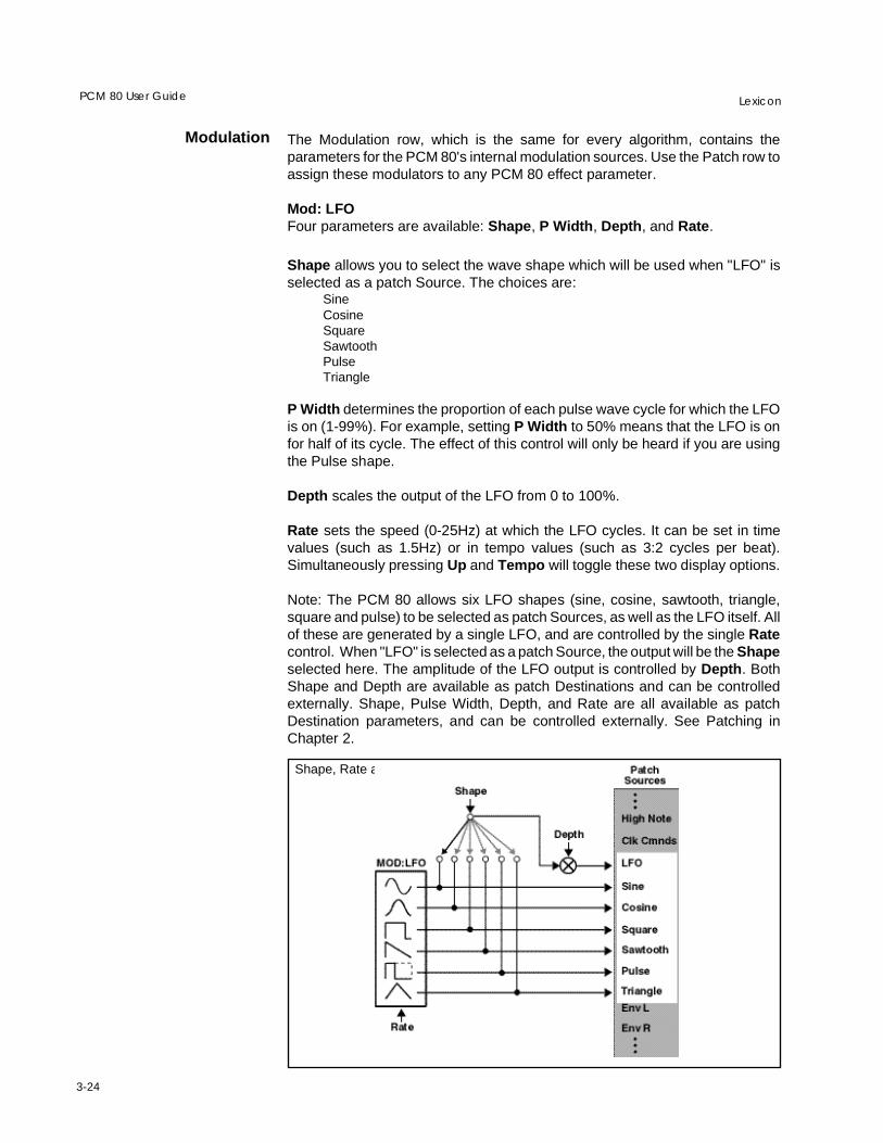
Lexicon
3-24
PCM 80 User Guide
The Modulation row, which is the same for every algorithm, contains theparameters for the PCM 80's internal modulation sources. Use the Patch row toassign these modulators to any PCM 80 effect parameter.
Mod: LFOFour parameters are available: Shape, P Width, Depth, and Rate.
Shape allows you to select the wave shape which will be used when "LFO" isselected as a patch Source. The choices are:
SineCosineSquareSawtoothPulseTriangle
P Width determines the proportion of each pulse wave cycle for which the LFOis on (1-99%). For example, setting P Width to 50% means that the LFO is onfor half of its cycle. The effect of this control will only be heard if you are usingthe Pulse shape.
Depth scales the output of the LFO from 0 to 100%.
Rate sets the speed (0-25Hz) at which the LFO cycles. It can be set in timevalues (such as 1.5Hz) or in tempo values (such as 3:2 cycles per beat).Simultaneously pressing Up and Tempo will toggle these two display options.
Note: The PCM 80 allows six LFO shapes (sine, cosine, sawtooth, triangle,square and pulse) to be selected as patch Sources, as well as the LFO itself. Allof these are generated by a single LFO, and are controlled by the single Ratecontrol. When "LFO" is selected as a patch Source, the output will be the Shapeselected here. The amplitude of the LFO output is controlled by Depth. BothShape and Depth are available as patch Destinations and can be controlledexternally. Shape, Pulse Width, Depth, and Rate are all available as patchDestination parameters, and can be controlled externally. See Patching inChapter 2.
Modulation
Shape, Rate and Depth can be controlled by a patch.

3-25
The Algorithms and Their Parameters
Mod: AR EnvThis envelope generator's output, when turned on, will go from 0 to127. Howquickly it goes from 0 to 127 is determined by the setting of Attack (0-10seconds). Once the envelope generator has reached 127, it remains there aslong as it is turned on. When it is turned off, it goes from 127 to 0, at the ratedetermined by Release (0 to 10 seconds).
T Src allows you to select a Source to turn the envelope generator on and off.
T Lvl allows you to select a specific threshold value which the T Src must reachto turn the envelope generator on.
The Mode parameter allows you to determine the behavior of the envelopecontroller in relation to the threshold value. Four settings are available: Repeat,One Shot, Retrigger, and Off.
Repeat As long as the threshold source remains at or above T Lvl,the envelope cycles from attack to release. If A=R, theoutput of the envelope is a triangle wave.
One Shot Once T Lvl is reached, the envelope will go through itsentire attack cycle. Once the attack cycle is completed, ifSource value is below T Lvl, the envelope will immediatelyfall at the specified Release rate. The envelope will gothrough its entire release cycle, even if the source subse-quently rises above T Lvl. If the Source value is at or aboveT Lvl, the envelope will remain at 127 until the T Src falls.
Retrigger As long as the level is at or above T Lvl, the envelope willgo through its attack cycle. If the level falls below T Lvlbefore attack is completed, the envelope immediately be-gins to release.Likewise, if the T Lvl is crossed again beforethe release is completed, the attack cycle will begin again.
Off This control turns the AR envelope off (and frees up proces-sor time). To optimize PCM 80 real-time response, set AREnv to Off when it is not being used.
Mod: Env L and Mod: Env RThese are left and right input signal envelope followers. The only availableparameter is Release which is set in milliseconds. This control allows you tospecify the release rate (0-10 seconds) when the input level drops.
Modulation cont'd.
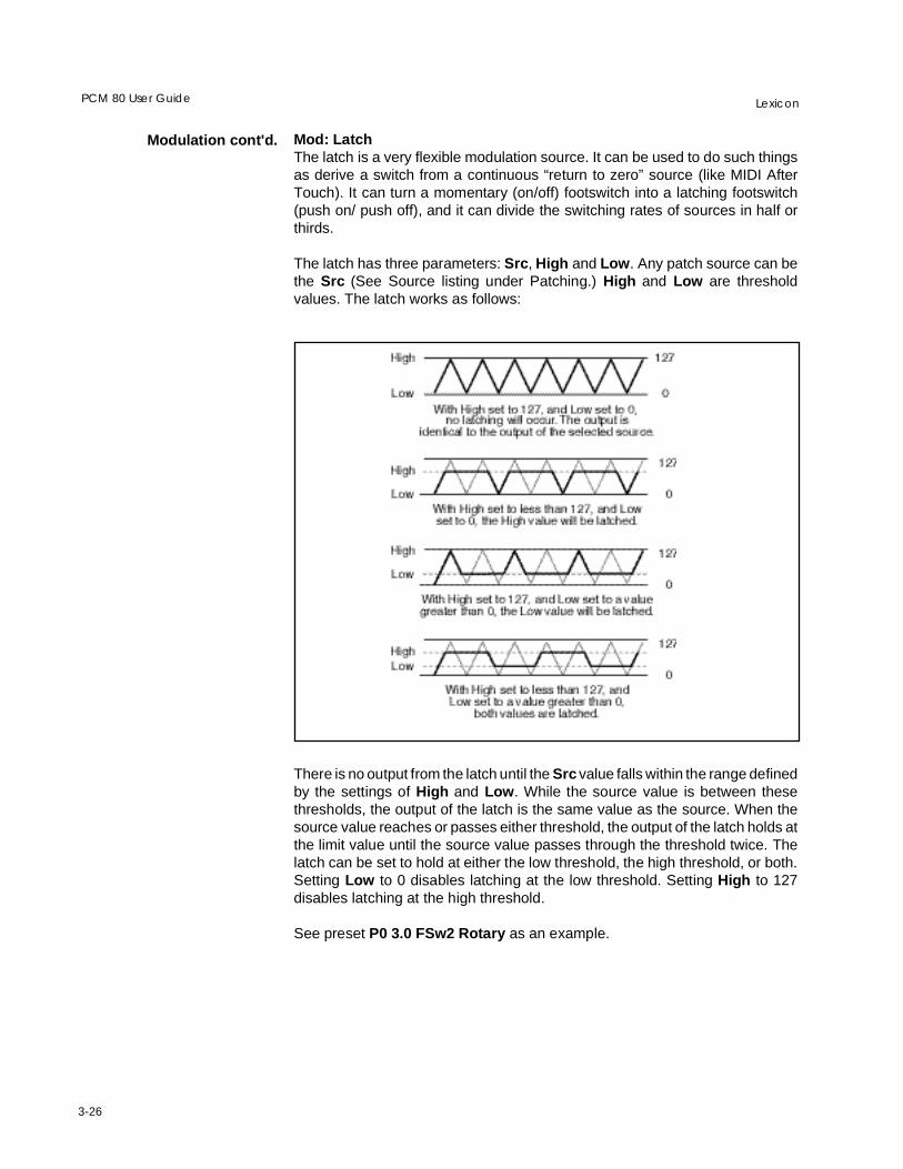
Lexicon
3-26
PCM 80 User Guide
Mod: LatchThe latch is a very flexible modulation source. It can be used to do such thingsas derive a switch from a continuous “return to zero” source (like MIDI AfterTouch). It can turn a momentary (on/off) footswitch into a latching footswitch(push on/ push off), and it can divide the switching rates of sources in half orthirds.
The latch has three parameters: Src, High and Low. Any patch source can bethe Src (See Source listing under Patching.) High and Low are thresholdvalues. The latch works as follows:
Modulation cont'd.
There is no output from the latch until the Src value falls within the range definedby the settings of High and Low. While the source value is between thesethresholds, the output of the latch is the same value as the source. When thesource value reaches or passes either threshold, the output of the latch holds atthe limit value until the source value passes through the threshold twice. Thelatch can be set to hold at either the low threshold, the high threshold, or both.Setting Low to 0 disables latching at the low threshold. Setting High to 127disables latching at the high threshold.
See preset P0 3.0 FSw2 Rotary as an example.

3-27
The Algorithms and Their Parameters
Mod: Sw 1 and Mod: Sw 2These are identical time switches. Each has five parameters: Rate, P Width,Mode, T Lvl and T Src.
Rate sets the speed at which the switch cycles. It can be set intime values (such as 1.5 Hz) or tempo values (such as 3:2Cycles per Beat). Simultaneously pressing Up andTempo will toggle these display options.
P Width determines the proportion of each switch cycle duringwhich the switch is on. For example, setting P Width to50% means that the switch is on for one-half of a cycle.
Mode determines the “shape” of the switch output. Three set-tings are available: Switch, Ramp, and Off. When Switchis selected, the transition from on to off is instantaneous,i.e. the switch output resembles a pulse wave. WhenRamp is selected, the transition from on to off is continu-ous, i.e. the switch output resembles a triangle or sawtoothwave.
Off turns the switch off (and frees up processor time). Tooptimize PCM 80 real-time response, set switch to Offwhen it is not being used.
T Lvl sets the threshold value at which the switch will begin tocycle.
T Src selects a patch source to drive the switch. The output of theswitch is 0 as long as T Src is set to a value below T Lvl.Once the source value reaches or passes T Lvl, the switchwill begin to cycle between on (127) and off (0) at the speedset by Rate.
Note that both Rate and P Width are available as patchDestinations, allowing them to be dynamically controlledby other patch sources. Switches are reset to the begin-ning of their cycles whenever Tap is pressed.
Modulation cont'd.

Lexicon
3-28
PCM 80 User Guide
A special, composite output of these switches, called Sw 1&2 is available as apatch source. The value of Sw 1&2 alternates between the output of Sw 1 andthe output of Sw 2. The alternation occurs on the transition from on to off. Notethat both Sw 1 and Sw 2 must be active for the alternation to occur.
Modulation cont'd.
Parameters in the Panning row provide control of panning of individual effects voices, as well as a Host panning parameter for all voices.
HostThe Pan Host provides simultaneous control over the panning of all voices in the effect. The range of the Pan Host is 50L (full left) through L1, C (Center), 1R through 50R (full right) for a total of 101 positions. The Host Pan is additive to the individual voice panners such that, if a voice is set to L10, and the Host is set to 20R, the voice will be at 10R.
VoicesIndividual pan controls are provided to position the output of each voice. The range of each voice is 50L (full left) through 1L, C (Center), 1R through 50 R(full right) for a total of 101 positions.
Panning
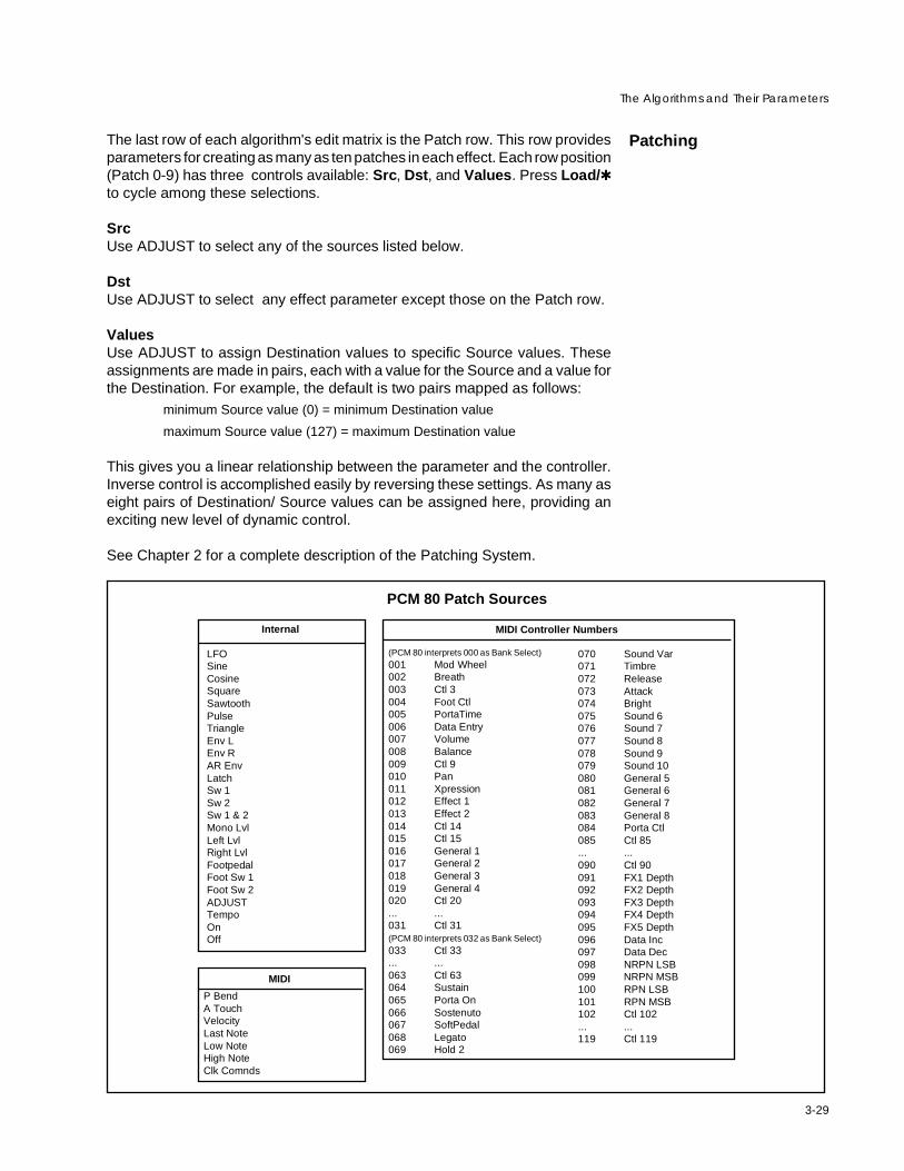
3-29
The Algorithms and Their Parameters
The last row of each algorithm's edit matrix is the Patch row. This row providesparameters for creating as many as ten patches in each effect. Each row position(Patch 0-9) has three controls available: Src, Dst, and Values. Press Load/to cycle among these selections.
SrcUse ADJUST to select any of the sources listed below.
DstUse ADJUST to select any effect parameter except those on the Patch row.
ValuesUse ADJUST to assign Destination values to specific Source values. Theseassignments are made in pairs, each with a value for the Source and a value forthe Destination. For example, the default is two pairs mapped as follows:
minimum Source value (0) = minimum Destination value
maximum Source value (127) = maximum Destination value
This gives you a linear relationship between the parameter and the controller.Inverse control is accomplished easily by reversing these settings. As many aseight pairs of Destination/ Source values can be assigned here, providing anexciting new level of dynamic control.
See Chapter 2 for a complete description of the Patching System.
Patching
Internal
LFOSineCosineSquareSawtoothPulseTriangleEnv LEnv RAR EnvLatchSw 1Sw 2Sw 1 & 2Mono LvlLeft LvlRight LvlFootpedalFoot Sw 1Foot Sw 2ADJUSTTempoOnOff
MIDI
P BendA TouchVelocityLast NoteLow NoteHigh NoteClk Comnds
MIDI Controller Numbers
070 Sound Var071 Timbre072 Release073 Attack074 Bright075 Sound 6076 Sound 7077 Sound 8078 Sound 9079 Sound 10080 General 5081 General 6082 General 7083 General 8084 Porta Ctl085 Ctl 85... ...090 Ctl 90091 FX1 Depth092 FX2 Depth093 FX3 Depth094 FX4 Depth095 FX5 Depth096 Data Inc097 Data Dec098 NRPN LSB099 NRPN MSB100 RPN LSB101 RPN MSB102 Ctl 102... ...119 Ctl 119
(PCM 80 interprets 000 as Bank Select)001 Mod Wheel002 Breath003 Ctl 3004 Foot Ctl005 PortaTime006 Data Entry007 Volume008 Balance009 Ctl 9010 Pan011 Xpression012 Effect 1013 Effect 2014 Ctl 14015 Ctl 15016 General 1017 General 2018 General 3019 General 4020 Ctl 20... ...031 Ctl 31(PCM 80 interprets 032 as Bank Select)033 Ctl 33... ...063 Ctl 63064 Sustain065 Porta On066 Sostenuto067 SoftPedal068 Legato069 Hold 2
PCM 80 Patch Sources

Lexicon
3-30
PCM 80 User Guide
Pitch The Resonant Chord algorithms: Res1>Plate and Res 2>Plate each have aPitch row that contains the parameters for setting and controlling the tuning ofthe effect's resonators. Each set of parameters is presented separately here.
Res 1>Plate Pitch parametersThe voice resonators take the audio impulse from a delay voice and “resonate”it at a desired pitch. Until a resonator is assigned a pitch, it does not resonate.The Res1 effect is a “round robin” pitch assign in that pitch changes areindividually assigned to one of (as many as) six voice resonators. For example,assume that all six voice resonators are active in the newly loaded effect, andthe first pitch assigned is A4. Voice 1’s resonator will be set to the A4 frequency.Assign B4, and Voice 2’s resonator will be set to that pitch. In this example, if weassign four more pitches (D5, G4, A#:Bb4, C5, for example), they will beassigned to the Voice 3, 4, 5, and 6 resonators, respectively. If a seventh pitchis assigned, for example, F3, Voice 1’s resonator will be changed from A4 to F3(the other resonators remain at the last assigned pitches).
AssignThis parameter has a range of C0 to G10 (128 pitches) to be convenient for MIDIpatching. As the value of this parameter is changed, each “next value” isassigned to the next active pitch resonator of the six possible active resonators.An example might be driving this parameter with a slow LFO to achieve an effectsomething like strumming the strings of an open piano.
TuningThis parameter allows you to tune the A440 reference of the box anywhere from430.0-450.0Hz in 0.1Hz increments.
ActiveThis parameter allows you to define the number of active voice resonators. Youcan choose from 0 (no resonators active) to 6. Setting the value to 1 will limit pitchassignments to Voice 1’s resonator. Setting the value to 2 will limit the roundrobin pitch assign to Voices 1 and 2. A value of 6 uses all the voice resonators.
A handy feature of this parameter is the ability to mute resonators. For example,you can patch this parameter to a footswitch or pedal, allowing you to drive theparameter value down to 0 at any time, causing the resonators to stop playingtheir last assigned pitches. You can then immediately drive it back up to thedesired number of active resonators. This “clears” the pitch assign for theresonators, so they don’t go back to playing their previous pitches, but rather waitfor the next pitch assign to come along before resonating.
UnisonThis is a simple On/Off control. When set to On, pitch assigns will be sentsimultaneously to all active resonators. When set to Off, pitch assigns willoperate in the round robin method described earlier. This allows you to setmultiple delay times for all Voices and allows a single pitch assign (rather than6 individual assigns) to set all the resonators to the same pitch. The pitch will ringout at 6 different delay times from the input impulse.
3-31
The Algorithms and Their Parameters
Res 2>Plate Pitch parametersThe voice resonators take the audio impulse from a delay voice and “resonate”it at a desired pitch. The Res2 effect is a “interval harmonization” pitch assign inthat pitch changes generate interval pitches to be assigned to the six voiceresonators.
Position 0 contains all of the pitch parameters which affect the voices in theremaining position in the row. Press Load/ to cycle through the selections atposition 0: Assign, Tuning, Active, Key, Scale, Root and Rule.
Assign This parameter has a range of C0 to G10 (128 pitches to beconvenient for MIDI patching). As the value of this parameter ischanged, each voice resonator is set to a pitch at the definedvoice’s interval (described later).
Tuning This parameter allows you to tune the A440 reference of the boxanywhere from 430.0-450.0Hz in 0.1Hz increments.
Active This parameter allows you to define the number of voiceresonators which are active. You can choose from 0 (noresonators active) to 6. Setting the value to 1 will permit onlyVoice 1’s resonator to ring out. Setting the value to 2 will permitVoices 1 and 2 to ring out. A value of 6 uses all the voiceresonators. A handy feature of this parameter is the ability tomute resonators. For example, you can patch this parameter toa footswitch or pedal, allowing you to drive the parameter valuedown to 0 at any time, causing the resonators to stop playingtheir last assigned pitches. You can then immediately drive itback up to the desired number of active resonators. This“clears” the note assign for the resonators, so they don’t go backto playing their previous pitches, but rather wait for the next pitchassign to come along before resonating.
Key This parameter establishes a key signature for the pitch selec-tion of the voice intervals. The range of this value is the 12 keysfrom C, C#, etc., up to B.
Scale This parameter establishes one of two scales of semitones: astandard Major scale (intervals of 2, 2, 1, 2, 2, 2, 1 half steps forthe scale), or a Harmonic scale (intervals of 2, 1, 2, 2, 1, 3, 1).
Root This parameter (with values of 1-7) establishes the root of thescale which, when combined with the scale, defines the mode.For example, with a Major scale selected, roots 1-7 define themodes — Ionian (Major), Dorian, Phrygian, Lydian, Mixolydian,Aeolian (minor) and Locrian.
Pitch cont'd.

Lexicon
3-32
PCM 80 User Guide
Rule This parameter has four values: Round Down, Round Up, ShiftDown, and Shift Up. Its exclusive purpose is to tell the intervalharmonizer what to do with out-of-key pitch assignments. Thevalues instruct the interval harmonizer as follows:
Round Down Take the input pitch assign, round it down ahalf-step to an in key pitch, then calculatethe interval pitch.
Round Up Take the input pitch assign, round it up ahalf-step to an in key pitch, then calculatethe interval pitch.
Both of these generate in-key harmonization.
Shift Down Take the input pitch assign, round it up ahalf-step to an in-key pitch, calculate theinterval pitch then shift the interval pitchdown a half-step.
Shift Up Take the input pitch assign, round it down ahalf-step to an in-key pitch, calculate theinterval pitch then shift the interval pitch upa half-step.
Both of these generate out-of-key harmonization.
Unison and Octave interval pitches strictly follow the input pitch assign. Anexample of how to use these follows the explanation of Voice Pitch intervals.
V1-V6 PitchThe Res2>Plate effect has an individual pitch interval control for each voiceresonator. The range of each control is up or down any scale interval through fiveoctaves and Unison, for a total of 81 possible settings. For example: an intervalof up one-fifth reads "+5th", and an interval of up one octave and a fifth reads"+1 Oct +5th". Down one-fifth reads "–5th", down one octave and a fifth reads"–1 Oct –5th".
Pitch cont'd.

3-33
The Algorithms and Their Parameters
An example application of Key, Scale, Root, Rule and Voice Pitch Intervals.
Active resonators set to 3.
The Key is C.
The Scale is Major.
The Root is 1. (C Major Ionian)
Voice 1 Pitch is assigned to Unison.
Voice 2 Pitch is assigned to +3rd.
Voice 3 Pitch is assigned to +5th. (Basic triad)
In-key pitch assignment examples:
1. Pitch Assign:C4. Voice 1 will resonate at C4, Voice 2 at E4, and Voice 3 atG4. (Standard chord in the key based on the tonic)
2. Pitch Assign: D4. Voice 1 will resonate at D4, Voice 2 at F4, and Voice 3 atA4. (Standard chord in the key based on the supertonic)
3. Pitch Assign: E4. Voice 1 will resonate at E4, Voice 2 at G4, and Voice 3 atB4. (Standard chord in the key based on the median)
4. Pitch Assign: B4. Voice 1 will resonate at B4, Voice 2 at D5, and Voice 3 atF5. (Standard chord in the key based on the leading tone)
Out-of-key pitch assignment — Pitch Assign: C#:Db4.
Rule: Round Down: Voice 1 will resonate at C#/Db4, Voice 2 at E4, and Voice3 at G4 diminished
Round Up: Voice 1 will resonate at C#/Db4, Voice 2 at F4, and Voice 3at A4 augmented
Shift Down: Voice 1 will resonate at C#/Db4, Voice 2 at E4, and Voice3 at G#:Ab4 minor
Shift Up: Voice 1 will resonate at C#/Db4, Voice 2 at F4, and Voice 3 atG#:Ab4 Major
Pitch cont'd.
Lexicon
3-34
PCM 80 User Guide
In the Resonant Chord algorithms: Res1>Plate and Res2>Plate, this row contains high cut filter and resonance controls for each voice, as well as Host high cut and resonance controls for all voices.
hst Res,hst HCPosition 0 of the Resonance row contains two Host parameters for the six resonator voices: hst Res and hst HC. (Press Load/ to toggle between them.) hst Res is a Host resonance control for all of the resonator voices. It allows the resonance settings for all voices to be scaled over a range of 0-100%. Use care when adjusting this value. The resonators will put out high levels if the input source has any components that are close in pitch to the resonator tunings.
The hst HC control allows the high cut filter settings for all voices to be scaled over a range of 0-100%.
V1Res,V1 HiCut-V6 Res,V6 HiCutTheV1-V6 Res controls set the amount and polarity of feedback for each voice. The HiCut controls set the high frequency cutoff frequency of the 6dB per octave low pass filter for each voice.
The Reverb Deisgn row, available in every algorithm, contains parameters that affect the structural aspects of the reverb effect.
SizeSize sets the rate of build-up of diffusion after the initial period (which is controlled by Diffusion). The Size control changes a reverb sound from very large to very small. Generally, you should set this control to approximate the size of the acoustic space you are trying to create, before adjusting anything else. The size in meters is roughly equal to the longest dimension of the space. Audio is temporarily muted when Size is changed.
DurationIn the Inverse algorithm, Duration determines the length of time, in milliseconds, which passes before the cutoff in Inverse effects.
AttackAttack is provided in the Plate algorithm to set the sharpness of the initial response to an input signal. High settings cause an explosive sound, while low settings cause the sound to build up more slowly with time. Attack only affects the level of sound within the first 50 milliseconds.
DiffusionA Diffusion control is provided in all algorithms. It controls the degree to which initial echo density increases over time. High settings of Diffusion result in initial build-up of echo density, and low settings cause low initial build-up. Echo density is also affected by Size; smaller spaces will sound denser. To enhance percussion, use high settings of Diffusion. For clearer and more natural vocals, mixes, and piano music, use low or moderate settings of Diffusion.
Resonance
RvbDesign

3-35
The Algorithms and Their Parameters
Shape, SpreadIn the Chamber and Infinite algorithms, Shape and Spread work together tocontrol the overall ambience of the reverberation created by the PCM 80. Shapedetermines the contour of the reverberation envelope. With Shape all the waydown, reverberation builds explosively, and decays quickly. As Shape isadvanced, reverberation builds up more slowly and sustains for the time set bySpread. With Shape in the middle, the build-up and sustain of the reverberationenvelope emulates a large concert hall (assuming that Spread is at least halfwayup, and that Size is suitably large — 30 meters or larger). Low Spread settingsresult in a rapid onset of reverberation at the beginning of the envelope, with littleor no sustain. Higher settings spread out both the buildup and sustain. In theInverse algorithm, Spread is fixed, and only a Shape control is available.
DefAvailable in the Concert Hall and Glide>Hall algorithms, Definition affects theecho density buildup rate during the latter part of the decay period. At 0, the rateis determined by the program material. Raising Definition causes the sound tobecome choppier — the decrease in density of the echoes creates increasinglydistinct, repetitive echo trails.
DepthAvailable in the Concert Hall and Glide>Hall algorithms, this control sets theoutput amplitude envelope, changing the listener's perspective from the front tothe rear of the hall.
SpinSpin affects the movement of the reverberation tail. The object of Spin is tocontinuously alter the timbre of the reverberant sound. This makes the resultmore natural, without making the position of instruments unstable. Spin shouldtypically be set to values between 10 and 50. Higher values may make the timbreof piano or guitar unstable.
ChorusIn the Concert Hall and the Glide>Hall algorithms Chorus randomizes delaytimes and introduces modulation to make reverberation sound less metallic.Increasing Chorus increases the rate of modulation. Because Chorusing cancause pitch variation, this parameter should be set with care when using sourceswith very little pitch wobble (such as guitar or piano). A good practice is toincrease the setting until pitch wobble becomes noticeable, then lower it slightly.
LinkThis control is available in all algorithms except Inverse. When Link is set to On,the reverb time (Mid Rt) and Spread scale linearly as the Size control is varied.For some special effects, Mid Rt, Spread and Size can be unlinked.
Rvb WidthIn all of the 4-Voice algorithms, this control performs the same function as FXWidth, but controls the audio of only the reverb and post delay reverb.
Rvb In/OutRvb In and Rvb Out control the level of the audio going into and coming out ofthe reverb effect. Rvb In has a range of Full (0dB) down to -85dB, and Off. RvbOut has a range of Full (0dB) down to -24dB, and Off. Rvb Out does not affectthe level of the pre-echoes set by the Ref Lvl and Eko Fbk parameters.
Rvb Design cont'd.

Lexicon
3-36
PCM 80 User Guide
The Reverb Time row, available in every algorithm, contains parameters that affect the time-based aspects of the reverb effect.
Mid Rt and Low RtMid Rt sets the reverb time for mid-frequency signals. Because low frequency reverb time (Low Rt) is a multiplier of Mid Rt, Mid Rt acts as a Host control for the reverb time.
Low Rt sets the reverb time for low-frequency signals, as a multiplier of the Mid Rt parameter. For example, if Low Rt is set to 2X, and Mid Rt is set to two seconds, the low frequency reverb time will be four seconds. For a natural-sounding hall ambience, we recommend values of 1.5X or less.
Low Slope and Mid SlopeThese parameters are only available in the Inverse algorithm. Low Slope determines the shape of the reverb envelope for low frequencies. When set to 0, the level of low reverb remains unchanged over its Duration, then cuts off abruptly (depending on the amount of diffusion in use). Setting Low Slope above 0 causes the level of low-frequency reverb to rise smoothly from soft to loud until the sound is cut off. The greater the slope, the softer the initial reverberation and the more pronounced its rise. With negative values, the low frequency reverb drops from its initial level to a quieter one before cutoff. The lower the slope, the more pronounced the dropoff.
Mid Slope is similar to Low Slope, but applies to middle and high frequencies. The actual frequencies affected are determined by Crossover.
CrossoverCrossover sets the frequency at which the transition from Mid Rt to Low Rt takes place. This control should be set at least two octaves higher than the low frequency you want to boost. For example, to boost a signal at 100Hz, set Crossover to 400Hz. (This setting works well for classical music.) Crossover works best around 400Hz for boosting low frequencies, and around 1.5 kHz for cutting low frequencies.
Rt HCRt HC sets the frequency above which a 6dB/octave low-pass filter attenuates the reverberated signal. It does not attenuate the reflections. High frequencies are often rolled off with this parameter, resulting in more natural-sounding reverberation.
Pre DelayPre Delay adjusts an additional time delay between the input of signal and the onset of reverberation. The maximum range is 930ms. This control is not intended to mimic the time delays in natural spaces. In real rooms, the build-up of reverberation is gradual, and the initial time gap is usually relatively short. Natural spaces are best emulated by adjusting Spread for the desired effective predelay.
InfiniteIn the Infinite algorithm, this control is provided to turn the infinite effect On or Off.
Rvb Time

3-37
The Algorithms and Their Parameters
You can set and display delay val-ues in units of time, or with tempovalues. Press Up and Tempo simul-taneously to toggle between thesetwo options. When time units areselected, delay times are set anddisplayed in milliseconds (From 0msto the maximum available delay forthat parameter). When tempo val-ues are selected, delay values areset and displayed as a ratio of ech-oes to beats (from 24:1 to 1:24). Thiswill automatically synchronize thedelay to the current tempo (MIDI,Internal, or TAP — see Tempo Modein Chapter 2.) For example, a delaysetting of 1:2 (1 echo for every 2beats) will produce half-note delayrhythms synchronized to the currenttempo.
RefLvl L&R, RefDly L&RThese controls provide pre-echoes to the left and right channels. The maximumrange for Inverse effects is 800ms. In all other effects it is 1.2 seconds. PressLoad/ to cycle through the selections.
EkoFbk L&R,EkoDly L&RAvailable in the Plate, Chamber and Infinite algorithms, these controls providea pre-echo of 1.2 seconds maximum to the left and right channels, withfeedback. Press Load/ to cycle through the selections.
PstMix, PstGldIn the 4-Voice Algorithms, these controls adjust a pair of delays after the reverb.Press Load/ to cycle through the selections: PstMix, Pst Dly L&R, GldRespand GldRange.
Pst MixIn the 4-Voice Algorithms, this parameter controls the mix of the reverb audiowith the post delayed reverb audio (0-100%).
Pst Dly L&RIn the 4-Voice Algorithms, these parameters control the time of the postdelay. The available range of 0-682ms can produce a variety of pitch shift,flange, or stutter effects on the reverb audio. (Expanding PCM 80 memorywill extend this range to 1365ms.)
GldRespIn the 4-Voice Algorithms, this parameter controls the response of the glide ofthe post delay. The range is 0-100, with a typical default setting of 50. This settingprovides a good, real-time glide. Changing a delay time from 0 to 100 ms witha glide response of 0, causes the glide delays to take a minute or more, allowingsubtle changes in delay times and echoes with no noticeable pitch shifting. Aglide response of 100 is ultrafast, causing high speed pitch shift, and evenchirping effects with large delay time changes.
GldRangeIn the 4-Voice Algorithms, this parameter controls the range over which changesto the post delay time will be performed as a glide. For example, if GldRange isset to 100ms, and the PstDly L and R times are varied over a range of 100ms,those delays will glide smoothly from one delay time to another. Suddenlychanging the delay time to a greater value, such as 200ms, will cause the audiodelay to change instantly to the new time without gliding. The available range is0-682ms, with 0 causing all delay time changes to be "instantaneous", and 682causing all delay time changes to glide. (Expanding PCM 80 memory will extendthis range to 1365ms.)
Rvb Time cont'd.

Lexicon
3-38
PCM 80 User Guide
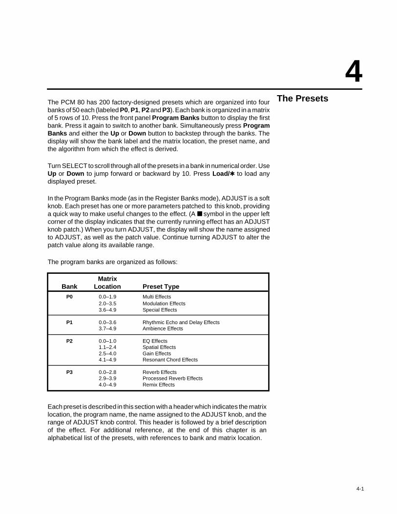
4-1
The Presets
The PCM 80 has 200 factory-designed presets which are organized into fourbanks of 50 each (labeled P0, P1, P2 and P3). Each bank is organized in a matrixof 5 rows of 10. Press the front panel Program Banks button to display the firstbank. Press it again to switch to another bank. Simultaneously press ProgramBanks and either the Up or Down button to backstep through the banks. Thedisplay will show the bank label and the matrix location, the preset name, andthe algorithm from which the effect is derived.
Turn SELECT to scroll through all of the presets in a bank in numerical order. UseUp or Down to jump forward or backward by 10. Press Load/ to load anydisplayed preset.
In the Program Banks mode (as in the Register Banks mode), ADJUST is a softknob. Each preset has one or more parameters patched to this knob, providinga quick way to make useful changes to the effect. (A symbol in the upper leftcorner of the display indicates that the currently running effect has an ADJUSTknob patch.) When you turn ADJUST, the display will show the name assignedto ADJUST, as well as the patch value. Continue turning ADJUST to alter thepatch value along its available range.
The program banks are organized as follows:
MatrixBank Location Preset Type
P0 0.0–1.9 Multi Effects2.0–3.5 Modulation Effects3.6–4.9 Special Effects
P1 0.0–3.6 Rhythmic Echo and Delay Effects3.7–4.9 Ambience Effects
P2 0.0–1.0 EQ Effects1.1–2.4 Spatial Effects2.5–4.0 Gain Effects4.1–4.9 Resonant Chord Effects
P3 0.0–2.8 Reverb Effects2.9–3.9 Processed Reverb Effects4.0–4.9 Remix Effects
Each preset is described in this section with a header which indicates the matrixlocation, the program name, the name assigned to the ADJUST knob, and therange of ADJUST knob control. This header is followed by a brief descriptionof the effect. For additional reference, at the end of this chapter is analphabetical list of the presets, with references to bank and matrix location.
4The Presets
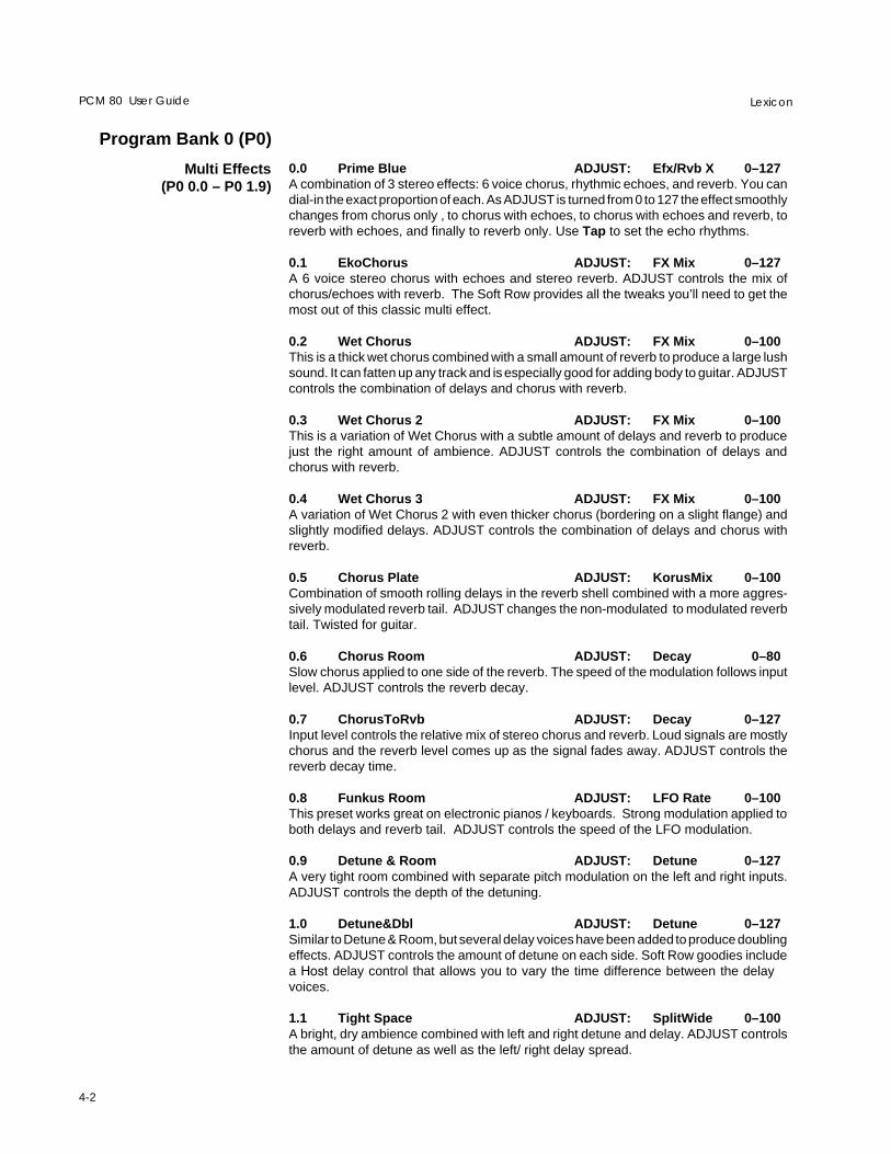
Lexicon
4-2
PCM 80 User Guide
Program Bank 0 (P0)
Multi Effects(P0 0.0 – P0 1.9)
0.0 Prime Blue ADJUST: Efx/Rvb X 0–127 A combination of 3 stereo effects: 6 voice chorus, rhythmic echoes, and reverb. You can dial-in the exact proportion of each. As ADJUST is turned from 0 to 127 the effect smoothly changes from chorus only , to chorus with echoes, to chorus with echoes and reverb, to reverb with echoes, and finally to reverb only. Use Tap to set the echo rhythms.
0.1 EkoChorus ADJUST: FX Mix 0–127 A 6 voice stereo chorus with echoes and stereo reverb. ADJUST controls the mix of chorus/echoes with reverb. The Soft Row provides all the tweaks you’ll need to get the most out of this classic multi effect.
0.2 Wet Chorus ADJUST: FX Mix 0–100 This is a thick wet chorus combined with a small amount of reverb to produce a large lush sound. It can fatten up any track and is especially good for adding body to guitar. ADJUST controls the combination of delays and chorus with reverb.
0.3 Wet Chorus 2 ADJUST: FX Mix 0–100 This is a variation of Wet Chorus with a subtle amount of delays and reverb to produce just the right amount of ambience. ADJUST controls the combination of delays and chorus with reverb.
0.4 Wet Chorus 3 ADJUST: FX Mix 0–100 A variation of Wet Chorus 2 with even thicker chorus (bordering on a slight flange) and slightly modified delays. ADJUST controls the combination of delays and chorus with reverb.
0.5 Chorus Plate ADJUST: KorusMix 0–100 Combination of smooth rolling delays in the reverb shell combined with a more aggres-sively modulated reverb tail. ADJUST changes the non-modulated to modulated reverb tail. Twisted for guitar.
0.6 Chorus Room ADJUST: Decay 0–80 Slow chorus applied to one side of the reverb. The speed of the modulation follows input level. ADJUST controls the reverb decay.
0.7 ChorusToRvb ADJUST: Decay 0–127 Input level controls the relative mix of stereo chorus and reverb. Loud signals are mostly chorus and the reverb level comes up as the signal fades away. ADJUST controls the reverb decay time.
0.8 Funkus Room ADJUST: LFO Rate 0–100 This preset works great on electronic pianos / keyboards. Strong modulation applied to both delays and reverb tail. ADJUST controls the speed of the LFO modulation.
0.9 Detune & Room ADJUST: Detune 0–127 A very tight room combined with separate pitch modulation on the left and right inputs. ADJUST controls the depth of the detuning.
1.0 Detune&Dbl ADJUST: Detune 0–127 Similar to Detune & Room, but several delay voices have been added to produce doubling effects. ADJUST controls the amount of detune on each side. Soft Row goodies include a Host delay control that allows you to vary the time difference between the delay voices.
1.1 Tight Space ADJUST: SplitWide 0–100 A bright, dry ambience combined with left and right detune and delay. ADJUST controls the amount of detune as well as the left/ right delay spread.
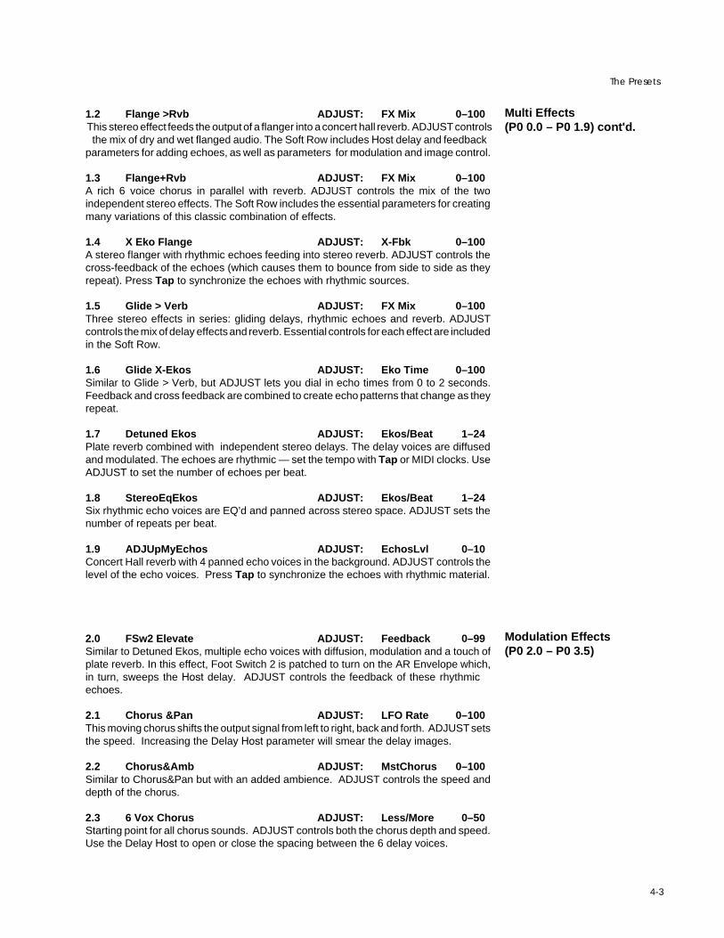
4-3
The Presets
1.2 Flange >Rvb ADJUST: FX Mix 0–100 This stereo effect feeds the output of a flanger into a concert hall reverb. ADJUST controls the mix of dry and wet flanged audio. The Soft Row includes Host delay and feedback
parameters for adding echoes, as well as parameters for modulation and image control.
1.3 Flange+Rvb ADJUST: FX Mix 0–100 A rich 6 voice chorus in parallel with reverb. ADJUST controls the mix of the two independent stereo effects. The Soft Row includes the essential parameters for creating many variations of this classic combination of effects.
1.4 X Eko Flange ADJUST: X-Fbk 0–100 A stereo flanger with rhythmic echoes feeding into stereo reverb. ADJUST controls the cross-feedback of the echoes (which causes them to bounce from side to side as they repeat). Press Tap to synchronize the echoes with rhythmic sources.
1.5 Glide > Verb ADJUST: FX Mix 0–100 Three stereo effects in series: gliding delays, rhythmic echoes and reverb. ADJUST controls the mix of delay effects and reverb. Essential controls for each effect are included in the Soft Row.
1.6 Glide X-Ekos ADJUST: Eko Time 0–100 Similar to Glide > Verb, but ADJUST lets you dial in echo times from 0 to 2 seconds. Feedback and cross feedback are combined to create echo patterns that change as they repeat.
1.7 Detuned Ekos ADJUST: Ekos/Beat 1–24 Plate reverb combined with independent stereo delays. The delay voices are diffused and modulated. The echoes are rhythmic — set the tempo with Tap or MIDI clocks. Use ADJUST to set the number of echoes per beat.
1.8 StereoEqEkos ADJUST: Ekos/Beat 1–24 Six rhythmic echo voices are EQ’d and panned across stereo space. ADJUST sets the number of repeats per beat.
1.9 ADJUpMyEchos ADJUST: EchosLvl 0–10 Concert Hall reverb with 4 panned echo voices in the background. ADJUST controls the level of the echo voices. Press Tap to synchronize the echoes with rhythmic material.
2.0 FSw2 Elevate ADJUST: Feedback 0–99 Similar to Detuned Ekos, multiple echo voices with diffusion, modulation and a touch of plate reverb. In this effect, Foot Switch 2 is patched to turn on the AR Envelope which, in turn, sweeps the Host delay. ADJUST controls the feedback of these rhythmic echoes.
2.1 Chorus &Pan ADJUST: LFO Rate 0–100 This moving chorus shifts the output signal from left to right, back and forth. ADJUST sets the speed. Increasing the Delay Host parameter will smear the delay images.
2.2 Chorus&Amb ADJUST: MstChorus 0–100 Similar to Chorus&Pan but with an added ambience. ADJUST controls the speed and depth of the chorus.
2.3 6 Vox Chorus ADJUST: Less/More 0–50 Starting point for all chorus sounds. ADJUST controls both the chorus depth and speed. Use the Delay Host to open or close the spacing between the 6 delay voices.
Modulation Effects(P0 2.0 – P0 3.5)
Multi Effects(P0 0.0 – P0 1.9) cont'd.

Lexicon
4-4
PCM 80 User Guide
2.4 Split C&E ADJUST: InputPan 0–100The left input is processed into a lush 3-voice chorus with the voice panners adjusted fromcenter to left. The right input is processed into a rhythmic 3-voice echo with the outputpanned from center to right. ADJUST cross-pans the inputs. 0 = left/right stereo,50 = mono, 100 = right/left stereo.
2.5 Env:PanKorus ADJUST: Chorus 0–127The AR Envelope drives the speed of the pan based on the presence or absence of inputsignal. ADJUST varies the chorus amount.
2.6 6 Vox Flange ADJUST: MstrDepth 0–100A rich stereo flanger with a touch of reverb. ADJUST controls the flange depth.
2.7 Mod Max ADJUST: Mod Knob 0–50 Multiple parameters all being modulated together. With a stereo input the LFO drives the input pans to each delay and reverb processor. A definite "twist your head off" effect. ADJUST controls several aspects of the modulation.
2.8 PreciseGlide ADJUST: Resonance 0–100 A very clean stereo gliding delay and reverb. ADJUST controls the resonance of the glide. Soft Row includes Host delay and feedback parameters so you can add stereo echoes to the effect.
2.9 Round 147 ADJUST: RotorRate 0–20 Big wooden rotary speaker cabinet miked fairly close. ADJUST sets the speed of the rotors. FX Mix is available in the soft row to control the amount of reverb relative to the total effect output.
3.0 FSw2 Rotary ADJUST: Width 0–100 A dual-rotor speaker cabinet with a very wide stereo spin and a touch of ambience. Use ADJUST to control the width and direction of the spinning rotors. 0= very wide left-to-right, 64 = mono, 127 = very wide right-to-left. Foot Switch 2 is patched to the Latch to toggle between slow and fast speeds. The AR envelope is used to simulate the inertial drag as the rotors speed up or slow down.
3.1 RotorCabinet ADJUST: Slow/Fast 0–1 Similar to FSw2 Rotor, but ADJUST is used to toggle the speed of the rotors between slow and fast. Soft Row parameters include FX Width which sets the width and direction of the spin.
3.2 MIDI Rotary ADJUST: EkoFbk 0–100 Similar to FSw2 Rotor, but with echoes added and the rotors patched up for MIDI control. MIDI After Touch toggles speed. Press hard to spin fast, press hard again to spin slow. ADJUST controls the amount of echo feedback. Use Tap to synchronize the echoes with rhythmic material.
3.3 Tiled Rotary ADJUST: Slow/Fast 0–1 The RotorCabinet effect in a tiled room. Try it with background vocals, as well as the usual keyboard and guitar sources. ADJUST toggles the spin rates between slow and fast.
3.4 RotoWood ADJUST: Speed 0–10 ADJUST quickly advances the speed of the rotors. Increase the Feedback Host for more upper rotor “howling”.
3.5 RandomImages ADJUST: ImageKnob 0–127 This effect works best with solo instruments or voices. Individual input notes come out at random locations in the stereo image. ADJUST varies delay time, adds chorusing, and turns up the level of tempo related echoes. Delays "creep" slowly out to new time values.
Modulation Effects(P0 2.0 – P0 3.5) cont'd.
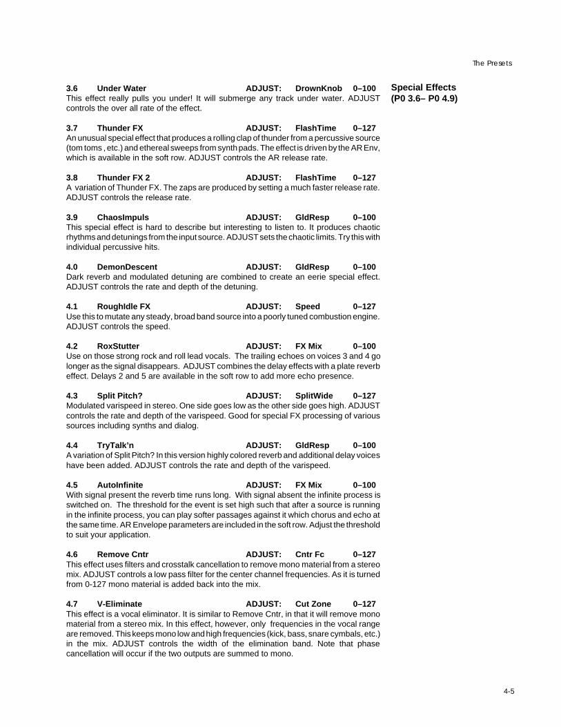
4-5
The Presets
3.6 Under Water ADJUST: DrownKnob 0–100This effect really pulls you under! It will submerge any track under water. ADJUSTcontrols the over all rate of the effect.
3.7 Thunder FX ADJUST: FlashTime 0–127An unusual special effect that produces a rolling clap of thunder from a percussive source(tom toms , etc.) and ethereal sweeps from synth pads. The effect is driven by the AR Env,which is available in the soft row. ADJUST controls the AR release rate.
3.8 Thunder FX 2 ADJUST: FlashTime 0–127A variation of Thunder FX. The zaps are produced by setting a much faster release rate.ADJUST controls the release rate.
3.9 ChaosImpuls ADJUST: GldResp 0–100This special effect is hard to describe but interesting to listen to. It produces chaoticrhythms and detunings from the input source. ADJUST sets the chaotic limits. Try this withindividual percussive hits.
4.0 DemonDescent ADJUST: GldResp 0–100Dark reverb and modulated detuning are combined to create an eerie special effect.ADJUST controls the rate and depth of the detuning.
4.1 RoughIdle FX ADJUST: Speed 0–127Use this to mutate any steady, broad band source into a poorly tuned combustion engine.ADJUST controls the speed.
4.2 RoxStutter ADJUST: FX Mix 0–100Use on those strong rock and roll lead vocals. The trailing echoes on voices 3 and 4 golonger as the signal disappears. ADJUST combines the delay effects with a plate reverbeffect. Delays 2 and 5 are available in the soft row to add more echo presence.
4.3 Split Pitch? ADJUST: SplitWide 0–127Modulated varispeed in stereo. One side goes low as the other side goes high. ADJUSTcontrols the rate and depth of the varispeed. Good for special FX processing of varioussources including synths and dialog.
4.4 TryTalk’n ADJUST: GldResp 0–100A variation of Split Pitch? In this version highly colored reverb and additional delay voiceshave been added. ADJUST controls the rate and depth of the varispeed.
4.5 AutoInfinite ADJUST: FX Mix 0–100With signal present the reverb time runs long. With signal absent the infinite process isswitched on. The threshold for the event is set high such that after a source is runningin the infinite process, you can play softer passages against it which chorus and echo atthe same time. AR Envelope parameters are included in the soft row. Adjust the thresholdto suit your application.
4.6 Remove Cntr ADJUST: Cntr Fc 0–127This effect uses filters and crosstalk cancellation to remove mono material from a stereomix. ADJUST controls a low pass filter for the center channel frequencies. As it is turnedfrom 0-127 mono material is added back into the mix.
4.7 V-Eliminate ADJUST: Cut Zone 0–127This effect is a vocal eliminator. It is similar to Remove Cntr, in that it will remove monomaterial from a stereo mix. In this effect, however, only frequencies in the vocal rangeare removed. This keeps mono low and high frequencies (kick, bass, snare cymbals, etc.)in the mix. ADJUST controls the width of the elimination band. Note that phasecancellation will occur if the two outputs are summed to mono.
Special Effects(P0 3.6– P0 4.9)

Lexicon
4-6
PCM 80 User Guide
4.8 NoCenter Eko ADJUST: Center Fc 0–127This is the same effect as Remove Center with delays added to the processed signal. Itallows you to add echoes to the left and right material without affecting the mono materialof a stereo mix or sub mix. For example, you can add additional echoes to a mix withoutaffecting the vocals, kick or snare. ADJUST controls a low pass filter for the centerchannel frequencies.
4.9 Rvb On L–R ADJUST: Decay 0–127Similar to NoCenterEko, this effect adds dense plate reverb to the left and right materialwithout affecting the mono material in a stereo mix. ADJUST controls the mid Rt of thereverberator.
Program Bank 1 (P1)
Rhythmic Echo andDelay Effects
(P1 0.0 – P1 3.6)
NOTE: The echoes in all of the Rhythmic Echo and Delay effects can be synchronizedto tempo. Tempo is set by dialing it in, pressing Tap, or selecting MIDI Clock as theTempo. (Tempo mode 0.2) Be sure to try these effects synchronized with MIDI sequenceand drum patterns.
0.0 [n]Ekos/Beat ADJUST: [n] 1–24This preset produces stereo echoes with a touch of reverb. ADJUST controls the number of echoes per beat. Soft Row goodies include controls for Host scaling of the delay rhythms and feedback, EQ and panning, as well as reverb parameters.
0.1 StereoTapDly ADJUST: hst Fbk 0–100 A variation of [n]Ekos/Beat this effect has left and right delay voices. ADJUST controls Host feedback for both voices. The Soft Row includes controls for rhythm, feedback and panning for each voice
0.2 OffBeat Eko ADJUST: DarkKnob 0–127 This variation of [n]Ekos/Beat produces a syncopated echo rhythm pattern. ADJUST controls high cut filters in the echo feedback paths – great for “tape”echo effects.
0.3 OffBeat Eko2 ADJUST: DarkKnob 0–127 Additional rhythmic delay voices are used to create a more complicated syncopation pattern than OffBeat Eko. ADJUST controls high cut filters in the echo feedback paths –great for “tape” echo effects.
0.4 Dotted 8ths ADJUST: EchoSlope 0–127 Rhythmic delay voices produce a dotted 8th-note pattern. ADJUST controls the slope of the first six repeats. 0 = loud to soft (normal echoes), 64 = six repeats of equal loudness, 127 = soft to loud (reversed echoes).
0.5 Shuffle Ekos ADJUST: Shufl Lvl 0–127 This effect creates echoes with a shuffle feel. One repeat on the beat followed by one repeat off the beat. ADJUST controls the relative levels of the on-beat and off-beat echoes. 0 = on-beat echo only, 127 = off-beat echo only.
0.6 Shuffles ADJUST: EchoSlope 0–127 Rhythmic delay voices produce a shuffle pattern. ADJUST controls the slope of the first six repeats. 0 = loud to soft (normal echoes), 64 = six repeats of equal loudness, 127 = soft to loud (reversed echoes).
Special Effects(P0 3.6– P0 4.9) cont'd.
4-7
The Presets
0.7 Sliding Eko ADJUST: Slide It! 0–100This stereo delay effect lets you dial in the perfect “feel” to match the moment. Two echoesare produced. One is fixed on the beat. The other can be slid in musical time anywherein front of or behind the beat by turning ADJUST. 0-49 = in front of the beat, 50 = on thebeat, 51–100 = behind the beat. Of course, the Soft Row contains additional controls forfine tuning the effect.
0.8 Six Trips ADJUST: EchoSlope 0–127Rhythmic delay voices produce a six note triplet pattern. Each repeat gets progressivelylouder. ADJUST controls the slope of the first six repeats. 0 = loud to soft (normal echoes),64 = six repeats of equal loudness, 127 = soft to loud (reversed echoes).
0.9 6 StrokeRoll ADJUST: Attack 0–127Turn a single drum hit into a six-stroke roll with this effect. ADJUST controls the attackof the first five repeats. 0 = loud to soft (normal echoes), 64 = five repeats of equalloudness, 127 = soft to loud (reversed echoes).
1.0 TapGated Rvb ADJUST: Gate dB 0–85This effect uses a tempo-controlled LFO as a rhythmic gate to the inputs of a large stereochamber. The gate is opened every other beat for a duration of one eighth-note. Use thisto add reverb to selected beats of a stereo source. (Try this one synchronized to MIDI witha drum machine as a source.) ADJUST controls the input levels in dB to the reverb whenthe gate is closed. 0 = always open (0dB), 85 = fully closed (-85dB). The Soft Row includesthe LFO parameters so you can adjust the overall timing of the gate.
1.1 TapEkoGate 1 ADJUST: GateWidth 0–127This effect uses a tempo-controlled LFO as a rhythmic gate to the inputs of a delay andreverb combination. The gate is opened once every four beats for a duration of one eighth-note. ADJUST determines the portion of the four beats in which the gate is open. 0 = openfor all four beats, 127 = open for only the first 16th note of four beats. The Soft Rowincludes the LFO parameters so you can adjust the overall timing of the gate.
1.2 TapEkoGate 2 ADJUST: GateWidth 0–127This is a variation of TapEkoGate 1 with different echo rhythms. ADJUST determines theportion of the four beats in which the gate is open. 0 = open four all four beats, 127 = openfor only the first 16th note of four beats. The Soft Row includes the LFO parameters soyou can adjust the overall timing of the gate.
1.3 TapEkoClear ADJUST: GateWidth 0–127This preset is similar to the two TapEkoGate presets, except that the rhythmic gate is alsopatched to clear the delay voices when it opens. This allows very high delay feedbackvalues to be used without creating long echo trails. ADJUST determines the portion of thefour beats in which the gate is open. 0 = open for all four beats, 127 = open for only thefirst 16th note of four beats. The Soft Row includes the LFO parameters so you can adjustthe overall timing of the gate.
1.4 Tap Chamber1 ADJUST: Width 0–90This preset is a tempo controlled variation of SnareChamber. The effect is a tight chamberwith liveness that is constantly changing. The change is tempo controlled. Press Tap tosynchronize it to the beat. ADJUST controls the width of the reverb within the overallstereo image of the effect (0 = mono, 45 = stereo, 90 = surround). Use this to open upsampled drum mixes.
1.5 Tap Chamber2 ADJUST: Decay 0–127This is a version of Vox Chamber with a rhythmic twist. The width of the reverb, within theoverall stereo image of the effect, is changed rhythmically by Sw 1. This change is tempocontrolled. Press Tap twice to synchronize to the beat. ADJUST controls reverb decay.
Rhythmic Echo andDelay Effects(P1 0.0 – P1 3.6) cont'd.

Lexicon
4-8
PCM 80 User Guide
1.6 LatchedEkos ADJUST: EchoWidth 1–99The inputs and outputs of stereo delays are gated on and off by two rhythmic switches.The Latch is used to trigger the AR envelope, which in turn alternates the left and rightdelay outputs. ADJUST controls how long the inputs to the delays remain open over aperiod of four beats.
1.7 X-PanEQ BPM ADJUST: Low Tone 0-60This effect cross-pans the inputs between independent left and right band pass filters andadds some bright, highly diffused reverb. The pan rate is tempo controlled. ADJUSTcontrols the low frequency limits of both bands.
1.8 Pan->Eko BPM ADJUST: DarkKnob 0–127This effect pans the inputs across the stereo inputs of a reverb and independent left andright delays, each with slightly different EQ. The pan rate is tempo controlled. ADJUSTcontrols the high frequency limits of both bands.
1.9 Tempo Verb ADJUST: Liveness 0–40In this tempo-based reverb effect, decay changes in tempo. Slow tempos yield longerreverb time; fast tempos result in shorter decay. Set tempo with two presses of Tap, orwith MIDI.
2.0 Tempo Gate ADJUST: High Cut 0-50This heavily gated reverb effect has duration set by tempo. Tap in two quarter-notes toset the gate duration.
2.1 Tape Echo ADJUST: DarkKnob 0–127This preset simulates a stereo tape echo. The echo rate is tempo controlled. Press Tapto synchronize with rhythmic material. ADJUST controls high frequency damping – theechoes get darker as they repeat. The Soft Row includes parameters for adding andreverb as well additional controls for the delays and filters.
2.2 NonLinear 1 ADJUST: EchoSlope 0–127This effect produces echoes with non linear decay. ADJUST controls the decay slope.0 = loud to soft (normal echoes), 64 = six repeats of equal loudness, 127 = soft to loud(reversed echoes). In this preset the slope is set to produce a simple reversed echo effect.The repeat rate is tempo controlled. The Soft Row contains parameters for controlling thestereo image, adding reverb, scaling the repeat rate, and more.
2.3 NonLinear 2 ADJUST: EchoSlope 0–127Similar to NonLinear 1, with some additional processing. Chorus and reverb have beenadded, and the delays bounce from side to side as they repeat. In this preset the slopeis set to 64 to produce repeats of equal loudness. The Soft Row includes parameters forcontrolling the stereo image, chorus depth and rate, etc.
2.4 NonLinear 3 ADJUST: EchoSlope 0–127This is a variation of NonLinear 2 with more radical processing and an inverted slope.
2.5 Six Across ADJUST: Spacing 0-100This multi-tap delay effect filters each voice to a specific bandbass with each tappositioned succesively across the panoramic spectrum. ADJUST controls the overallspacing between the voices.
2.6 BandEko Rvb ADJUST: Center Fc 0–127In this preset, the outputs of a stereo band pass filter are sent to left and right rhythmicdelays. These delays are in the reverb diffusor loop. The effect produces diffuse, highlycolored echoes and reverb. Use ADJUST to set the center frequency of the band passfilter.
Rhythmic Echo andDelay Effects
(P1 0.0 – P1 3.6) cont'd.
4-9
The Presets
2.7 BandEkoSweep ADJUST: hst Fbk 0–100 A variation of BankEko Rvb. In this preset, the center frequency of the band pass filter is swept by the LFO producing echoes of shifting colors. Reverb and diffusion are turned off, but you can add them in from the Soft Row. ADJUST controls Host feedback for the left and right delays.
2.8 LFO EQ Echo ADJUST: LC Depth 0–100 A stereo rhythmic effect created by modulating low cut and high cut filters with the LFO sine and cosine waves. Interesting on rhythm tracks and individual instruments. ADJUST controls the depth of the low cut modulation.
2.9 Chase Echo ADJUST: ChaseRate 0–100 This is LFO EQ Echo with panning added to the filtered delay outputs. ADJUST controls the pan rate.
3.0 Panned Dlys ADJUST: hst Fbk 0–100 In this effect, a pair of delays are panned to produce echoes that drift across stereo space.
ADJUST controls the feedback of both delays. More goodies await you in the Soft Row.
3.1 X-Pan Delays ADJUST: hst Fbk 0–100 The outputs of the delay pair are cross-panned in this effect. Mono material will produce echoes that repeat, but remain in the center. Stereo material will slowly swap left and right as it repeats. Use ADJUST to set the feedback for both delays.
3.2 Dly>EQ>Pans ADJUST: hst Fbk 0–100 The input signal is split into two frequency bands by this effect. The two bands are then sent through two different rhythmic delays whose outputs are panned in opposite directions. This effect deconstructs the tone of input material, except when the panning and delay rhythms align in the center of the stereo field. Try it with a drum mix or other broad band material. Use ADJUST to set the feedback for both delay voices.
3.3 Ekoz 4 Drums ADJUST: FX Mix 0–100 This preset is a space setter for percussive instruments. It combines a short plate reverb effect with four high density echoes which are highly diffused. ADJUST varies the amount of delay effect to reverb effect.
3.4 Haas PanKnob ADJUST: L=0, R=127 0–127 A panner that uses the slight differences in left and right channel delay to produce panning without changing relative levels. Use ADJUST to pan from left to right.
3.5 Dial a Delay ADJUST: Delay 0–100 This one is your basic delay. Use ADJUST to dial-in up to 2.5 seconds of stereo delay. The Soft Row will take you beyond the basics, with parameters for reverb design, EQ and feedback.
3.6 PrecisionDly ADJUST: L ms/100 0–100 Use this preset if you need precise alignment of left and right channel audio. ADJUST allows you to offset the left channel by up to 1 ms in 100 increments. The Soft Row contains two sets of additional delay controls for the left and right channels, each with 1ms resolution, as well as independent level and panning controls.
Rhythmic Echo andDelay Effects(P1 0.0 – P1 3.6) cont'd.

Lexicon
4-10
PCM 80 User Guide
3.7 PhoneOrRoom? ADJUST: Pick One 0–1 Use ADJUST to choose between a mono telephone filter and a small room with stereo ambience. The Soft Row provides access to the filter controls as well as reverb design parameters.
3.8 CheapTV Room ADJUST: The Walls 1–10 This stereo preset simulates the sound of a Lo-Fi TV in a small room. Use ADJUST to change the reflectivity of the walls. The Soft Row provides access to the filter controls as well as reverb design parameters.
3.9 Empty Stage ADJUST: Liveness 0–100 Made for creating live sounding spaces. ADJUST opens the space to be more reflective and airy.
4.0 Tomb Room ADJUST: The Walls 1–10 Use this ambience preset to place source material within a very reflective tomb. ADJUST moves the source deeper into this scary space.
4.1 Comb Room ADJUST: Tone 0–100 This effect provides a tunable comb filter and reverb to produce a highly colored ambience. Use ADJUST to change the tuning of the comb filter.
4.2 Zoom Over ADJUST: Speed 1–25 Run an effect (or even a continuous synthesizer drone) into this preset, and the sound will approach you from the center, spread out to the sides as it passes overhead, and recede into the distance behind you. ADJUST controls the speed of the fly-by. This effect will image properly in either 2-channel or Surround mixes.
4.3 OneShotCarBy ADJUST: Speed 1–100 Input level triggers this left-to-right drive-by. When signal is detected, it will move from left to right. Doppler pitch shift is simulated as the image moves across the stereo field. Use ADJUST to set the speed of the drive-by. Once audio has been detected, the effect will cycle once. To drive by again, stop and restart the audio track. To reverse the direction of the effect, set the Width parameter to –45 — you’ll find it in the Soft Row.
4.4 AmbientCarBy ADJUST: Speed 1–100 This is a variation of OneShotCarBy. In this preset the effect is enhanced with the addition of some stereo ambience. Also, in this variation the effect repeats automatically. ADJUST controls the speed of the drive-by.
4.5 HeadOn CarBy ADJUST: Speed 1–100 This preset uses less ambience than ZoomOver, and is more appropriate for things that approach on the road than in the air. ADJUST sets the speed of the effect. This effect will image properly in either 2-channel or Surround mixes.
4.6 2WayStreet ADJUST: Speed 1–100 Another variation of AmbientCarBy. This preset produces both left-to-right and right-to-left drive-by effects — like listening to the sound of traffic on a two-way street. The speed for each direction is slightly different. ADJUST is a Host speed control for both eastbound and westbound traffic.
4.7 IntoTunnel ADJUST: Speed 1–25 This preset simulates the sound of a source approaching you from the side, passing you and then entering a tunnel. ADJUST controls the speed of the source. To reverse the direction of the effect, set the Width parameter to –45 — you’ll find it in the Soft Row.
Ambience Effects(P1 3.7 – P1 4.9)

4-11
The Presets
4.8 2WayTunnel ADJUST: Speed 1–100This is a variation of IntoTunnel. The source approaches and enters the tunnel, then turnsaround and comes back. Use ADJUST to control the speed.
4.9 FinishLine ADJUST: Speed 1–100This preset adds two pairs of stereo delays to the basic drive-by effect to simulate the 1st,2nd, and 3rd place cars crossing the finish line. ADJUST controls the speed. Be sure totry this and the other drive-by effects with different types of source material. Almost anycontinuous source will produce interesting spatial sound effects. Low, buzzy synthesizertones work particularly well.
0.0 StereoLoPass ADJUST: CutOff 0–127This effect is a combination of a stereo low pass filter and a stereo reverb, with the twoeffects in parallel. Use ADJUST to set the cut off frequency of the filter. The reverb mixis turned all the way down — you can add reverb by changing the FX Mix parameter inthe Soft Row, where you’ll also find additional parameters for delay voices, and image.
0.1 Low Pass HiQ ADJUST: Cutoff 0–127The same basic effect as StereoLoPass, but with feedback adjusted to produce a moreresonant filter. ADJUST sets the cutoff frequency of the filter.
0.2 Low Pass LFO ADJUST: Depth 0–127The cutoff of the stereo low pass filter is swept with a rhythmic LFO sine wave. Press Tapto synchronize the sweep with rhythmic material. ADJUST controls the low frequency limitof the sweep.
0.3 StereoHiPass ADJUST: Cutoff 0–127A combination of a stereo high pass filter and a stereo reverb, with the two effects inparallel. Use ADJUST to set the cutoff frequency of the filter. The reverb mix is turned allthe way down — you can add reverb by changing the FX Mix parameter in the Soft Row,where you’ll also find additional parameters for delay voices, and image.
0.4 StereoB-Pass ADJUST: Center 0–127A combination of a stereo band pass filter and a stereo reverb, with the two effects inparallel. Use ADJUST to set the center frequency of the filter. The reverb mix is turnedall the way down — you can add reverb by changing the FX Mix parameter in the Soft Row,where you’ll also find additional parameters for delay voices, and image.
0.5 Stereo Notch ADJUST: Center 0–127A variation of StereoB-Pass which combines a phase inverted output of the band passfilter with unprocessed signal to create a notch filter. ADJUST sets the center frequencyof the notch.
0.6 SweptNotches ADJUST: Rate 0–100This preset produces vowel-like sounds by sweeping two pairs of notches with twoindependent time switches. This effect will produce very unusual tonal variations frombroad band sources (rich pads, drums, industrial sound effects, etc.) It also generates agood deal of spatial movement within a stereo or Surround mix. ADJUST controls the rateof the sweeps.
0.7 Env Notches ADJUST: Release 0–100This preset will produce vocalization effects from dynamic sources. The inputs aresummed to mono, and the notch filters which are tuned to vocal formants are swept bythe resulting input envelope. ADJUST controls the release rate of the input envelope.
Ambience Effects(P1 3.7 – P1 4.9) cont'd.
Program Bank 2 (P2)
EQ Effects(P2 0.0 – P2 1.0)
Lexicon
4-12
PCM 80 User Guide
0.8 BandReject 4 ADJUST: FX Mix 0–100Three independent modulators are used to sweep filters and pan the outputs of thispreset. The result is an effect with constantly changing tonal and spatial characteristics.A touch of reverb adds some overall ambience. Use ADJUST to set the mix of filters andreverb.
0.9 WaaPedalEko ADJUST: FeedBack 0–10Wah-wah with echoes. Foot pedal is patched to filter cutoff. ADJUST controls echofeedback.
1.0 RotorWaa ADJUST: Rate 0–10A tempo controlled wah-wah effect. ADJUST controls the rhythm of the modulator.
1.1 Movable Echo ADJUST: Position 0-127This preset is designed for use with either stereo or Surround mixes. It is a dual delayeffect that can be positioned anywhere between the center, side and rear channels.ADJUST sets the position. 0 = center, 64 = side channels, 127 = rear channel.
1.2 Movable Hall ADJUST: Position 0–127Like Movable Echo, this preset is designed for use with either stereo or Surround mixes.It is a concert hall reverb effect that can be positioned anywhere between the center, sideand rear channels. ADJUST sets the position. 0 = center, 64 = side channels, 127 = rearchannel.
1.3 Go Away ADJUST: How Far? 0–127Use this preset to take a stereo source and move it anywhere from in your face to far, faraway. Use ADJUST to move the source away from you. 0 = unprocessed stereo, 127 =far away. As ADJUST is increased, EQ, reverb and stereo width are all changed toproduce the composite effect. This effect is compatible with stereo and Surround mixes.
1.4 Circular Pan ADJUST: Rate 0–100Similar to Go Away, this preset sums the inputs to mono and uses the LFO to control EQ,reverb and stereo width to pan the sound through a circular orbit. From right throughcenter,to left through rear, to right. As the sound approaches the center, it grows brighter,louder and dryer. As it recedes towards the rear, it grows darker, softer and morereverberant. In a Surround mix, the center and rear positions of the orbit will feed only thecenter and rear channels of the mix. ADJUST controls the rate of the pan.
1.5 Spatial Hall ADJUST: Position 0–35A multi-dimensional preset which changes as you increase or decrease the ADJUSTknob value. This preset is not mono compatible.
1.6 Rear of Hall ADJUST: Decay 0–60This is a really huge space and you’re in the back of it. ADJUST changes the reverberationcharacteristics, making it boomier.
1.7 Backstage ADJUST: How Far? 0–127Remember what the concert sounded like from the green room? If you need to re-createthat ambience, this preset will take you there and let you wander around. Turn up ADJUSTto travel further from the stage until, finally, you’re out in the parking lot. The Soft Rowprovides reverb parameters that will let you fine tune the the hall to fit your needs.
1.8 Steered Rear ADJUST: Decay 0–10The Width parameter steers this plate effect from front to back after the AR releasesbased on input level. ADJUST controls reverb decay. Due to the strong spatial positioningat the end of the decay, this preset is not mono compatible.
Spatial Effects(P2 1.1 – P2 2.4)
EQ Effects(P2 0.0 – P2 1.0) cont'd.

4-13
The Presets
1.9 Too Deep! ADJUST: Decay 0–40The left and right envelope followers control the post delay glides while the AR generatorcontrols reverb width. ADJUST controls reverb decay.
2.0 Dyna-Hall ADJUST: Decay 0–130A tamer version of Too Deep! No envelope chorusing. Good, beautiful, straight ahead,and spacious.
2.1 RotoRox ADJUST: FX Mix 0-100RotoRox crossfades deeper into two delay voices when the envelope follower detects anabsence of input. Great vocal effects for thickly-produced rock and roll. ADJUST will addmore or less reverb into the effects mix.
2.2 RotoRoomVox ADJUST: Decay 0–100This medium large sized room continuously changes spatial width according to the speedof the LFO which tracks the input. Faster with less input, slower with more input. ADJUSTcontrols reverb decay. Nice roomy effect for background vocals.
2.3 RotoRoom ADJUST: Decay 0–60Similar to RotoRoomVox except the speed of the spatial width modulation is stable, withthe speed of the LFO constant. Room is smaller, more dense-sounding and brighter.
2.4 RotoRoom#2 ADJUST: Rt & Rate 0–60Speed and reverb decay are tied to ADJUST. Way cool on a stinger sound effect!Dynamically spacious and not mono compatible.
2.5 Tremolo Tap1 ADJUST: Depth 0–127This is a basic tremolo effect with a small amount of ambience added. The effect is truestereo. The left and right channels are processed separately to maintain the image ofstereo source material. The tremolo rate is tempo controlled (2 cycles/beat). Press Tapto synchronize the effect with rhythmic material. ADJUST sets the tremolo depth. 0 = notremolo, 127 = maximum tremolo.
2.6 X-TremoloTap ADJUST: Depth 0-127This a variation of TremoloTap1. In this preset the left and right modulation are 90° outof phase, producing a stereo effect that doesn’t collapse in a mono mix. If the input sourceis mono, the sound will seem to move from side to side. If the input source is stereo (ortwo different mono sources) the left and right channels will alternately grow loud and soft.The modulation rate is tempo controlled. ADJUST controls the tremolo depth for bothchannels. 0 = no tremolo, 127 = maximum tremolo.
2.7 Panner BPM ADJUST: Pan Phase 0–1This effect is a tempo controlled auto panner with the inputs independently panned leftand right. ADJUST allows you to set the relative phase of the input panning. 0 = in phase,1 = 90° out of phase. In the preset, the panning is 90° out of phase. If the input source ismono it will pan from side to side. If the input source is stereo (or two different monosources), the two sources will chase each other between the speakers. Set ADJUST to0 for “normal” auto panning.
2.8 Nice Pan! ADJUST: FX Mix 0-100This preset combines static time based delays which move back and forth in the stereofield with a short, bright chorus plate. ADJUST varies the delay and reverb mixing. Greatfor acoustic guitars.
Spatial Effects(P2 1.1 – P2 2.4) cont'd.
Gain Effects(P2 2.5 – P2 4.0)
Lexicon
4-14
PCM 80 User Guide
2.9 Spin & Duck ADJUST: Spin Rate 0–127In this preset, panning is combined with 6-voice chorus delays and reverb to produce arich spacious effect. ADJUST controls the panning rate. 0 = slow, 127 = fast. The delaysare tempo controlled and ducked by input level. They won’t be heard during activepassages, but will fade up in the spaces between phrases.
3.0 MultiFxFade ADJUST: FX Mix 0–100In this preset, the AR envelope is used to create a moderate fade-in of chorus, delay andreverb effects. ADJUST controls the mix of chorus/delay and reverb. The Soft Row hasall the essentials for tweaking the three basic effects, as well as the AR envelopeparameters so you can fine tune the fade in rate and threshold. Try this with guitars andkeys.
3.1 Ghost ADJUST: FadeShape 0–100Source material is accompanied by a ghostly image of itself. Not quite reverb, not quitebackwards audio. ADJUST controls the contour of the fade in of the effect. This presetworks well with short percussive sources as well as more sustained ones.
3.2 Ghost Flange ADJUST: FadeShape 0–100This is a variation of Ghost with some flanging added. Try this with lead guitar. ADJUSTcontrols the contour of the fade in.
3.3 GhostVibrato ADJUST: FadeShape 0–100Another Ghost variation. This one will produce a delayed vibrato on sustained notes.ADJUST controls the contour of the fade-in.
3.4 AutoFadeIn 1 ADJUST: FX Mix 0–127This preset senses input level to produce an automatic volume swell into a chorus/delayreverb effect. Sounds great with guitar and keyboard chords.The fade in rate is moderate.ADJUST controls the mix of chorus/delay and reverb effects. The Soft Row includesparameters for all three effects as well as the envelope parameters which set thecharacteristics of the fade-in.
3.5 AutoFadeIn 2 ADJUST: Fade Rate 0–100This variation of AutoFadeIn allows you to set the fade-in rate with ADJUST.
3.6 AutoFadeIn 3 ADJUST: Rvb Lvl 0–127This variation of AutoFadeIn 1 has shorter delay times and a lighter touch on the choruseffect. ADJUST sets the mix of chorus/delay and reverb effects.
3.7 ChordSwells ADJUST: Rvb Lvl 0-127A more dramatic version of AutoFadeIn. The fade time is quite long, and the chorus anddelay effects are fairly strong. Try it with sustained piano or guitar chords. ADJUSTcontrols the mix of chorus/delay and reverb.
3.8 BowedChords ADJUST: FX Mix 0–100A more subtle version of AutoFadeIn. Chorusing is turned off and delays are moresubdued. This is essentially a volume swell into reverb. Use it to pull cello-like tones fromsustained notes or block chords. Very nice with grand piano. ADJUST sets the mix ofclean echoes and reverb.
3.9 BowedEchoes ADJUST: FX Mix 0–100In this preset, input level controls echo feedback as well as triggering the fade-in.Feedback is reduced when the signal is loud and turned up when the signal fades out.This produces echoes with soft attacks that appear when the input signal drops. ADJUSTcontrols the mix of echoes and reverb.
Gain Effects(P2 2.5 – P2 4.0) cont'd.

4-15
The Presets
4.0 Pedal Swell ADJUST: FX Mix 0–100This is a combination of four 400 ms delays, a slight amount of chorus, and just a hint ofreverb. The foot controller is controlling the left and right input levels which allows you toget majestic volume swells. ADJUST controls the combination of delays and chorus withreverb.
4.1 Rez Climber ADJUST: Tuning 0–60Try this preset with dialog or unpitched source material. It is a special effect thatdynamically sweeps the resonators through the 2nd, 3rd, 4th and 5th pitches of theharmonic series. The sweep is controlled by the AR Env, which is triggered by mono inputlevel. ADJUST sets the fundamental pitch for the series.
4.2 Chord Walk ADJUST: High Cut 0–50This preset uses the resonators to generate a rhythmic chord pattern from unpitchedsource material. ADJUST controls the high frequency content of the chords. The timeswitches, Sw 1 and Sw 2 are used to change the chord root-note and mode and also varythe rhythm. Listen to this effect with a simple kick, snare and hi-hat pattern as an inputsource. Press Tap twice to synchronize the tempo of the effect with the tempo of the drumpattern.
4.3 Mars Bars ADJUST: High Cut 0–50In this preset, the resonators are used to create a truly weird and spacey special effect.Use any continuous sound effect, dialog, or even instrumental tracks as source material.The tuning of the resonators is swept slowly through a series of pitches by the LFO. Theresulting sound is quite unusual (an orchestra from another planet?). ADJUST controlsthe overall high frequency content of the effect. Be sure to check out the Soft Row, whichcontains parameters for tuning, voice assignment and more.
4.4 ModalImpulse ADJUST: Tone 0–50The resonators in this preset are tuned to arpeggiate a modal 7th chord. ADJUSTchanges the overall tone of the arpeggiated notes. The rhythm of the arpeggio is tempocontrolled. Press Tap twice to synchronize it to the beat. The effect works well with singlepercussion hits (try it with kick or snare). You can change the key, scale, and root noteof the arpeggio by playing with the Pitch sub parameters in the Soft Row. You’ll also findcontrols for reverb and delay there as well.
4.5 Major Minor ADJUST: Tone 0–50This effect in this preset builds a 6-note modal chord one note at a time. Use a singlepercussion hit as an input source (a slowly repeating snare hit works well). The notes inthe chord are added slowly over 24 beats. The effect is tempo controlled. Press Tap twiceto synchronize it to the beat. ADJUST changes the overall tone of the chord notes. As thechord builds, it is changed rhythmically between major and minor scales. The root noteof the chord is also changed in a rhythmic manner. The LFO controls the rate of the buildand the major minor shift. Switch 2 controls the changing root notes.
4.6 MIDIChords ADJUST: Sparkle 0–5This preset is driven by MIDI Note Number. Resonators follow the note in a diatonic tonecluster. ADJUST controls the brightness of the resonators. If the audio source is the sameas the MIDI source (a synthesizer), the effect is a little like harmonization. If the audiosource is different, the effect is much harder to describe. This preset will pass audio ifthere is no MIDI input.
Gain Effects(P2 2.5 – P2 4.0) cont'd.
Resonant Chord Effects(P2 4.1 – P2 4.9)

Lexicon
4-16
PCM 80 User Guide
4.7 LvlSweeper ADJUST: Color 0–24This preset is driven by level. Any input that exceeds the input threshold will cause a littleburst of resonators that quickly swirl through the stereo field. ADJUST controls the pitchrange of the resonators.
4.8 Sweeper ADJUST: Pitch 0–24This preset is a resonant arpeggiator in which a tempo-driven LFO controls the resonatorpitches. ADJUST controls the pitch range of the arpeggio effect.
4.9 MIDISustain ADJUST: Bright 0–5This preset requires MIDI note input or it will not pass audio. Resonators are assigned asthe notes are played (when playing chords, it's best to spread them a little). Footswitch2 works like a piano damper pedal. When the audio source is the same as the MIDI source,the effect is a little like playing a piano while holding down the pedal. When the audiosource is different, well ... ADJUST controls the brightness of the resonators.
0.0 Small+Stage ADJUST: Stage Lvl 0–50This preset combines a smooth, small reverberant space with several stage reflections.Use ADJUST to set the stage reflection level.
0.1 Small Room ADJUST: Liveness 0–60Use ADJUST to quickly change the ambient characteristics of this typically tight soundingroom. Great for ADR work.
0.2 Living Room ADJUST: Decay 0–60Another ADR preset,medium spaced but with a short Rt. ADJUST quickly changes if notperfect for your application.
0.3 Brick Kick ADJUST: Liveness 0–100Kicks *ss on kick drums or the entire submix. ADJUST increases the liveness of thechamber.
0.4 Large Room ADJUST: Decay 0–60A perfectly smooth listening room with medium diffusion. Very natural sounding on anysound source. ADJUST lengthens or shortens the reverb decay.
0.5 SnareChamber ADJUST: Liveness 0–60Like Brick Kick, ADJUST increases the liveness of the space. A classic from the PCM 70.
0.6 Tiled Room ADJUST: Decay 0–60A future classic... ADJUST controls reverb decay.
0.7 Rich Chamber ADJUST: Decay 0–60Smooth and full sounding. ADJUST varies reverb decay.
0.8 Vox Chamber ADJUST: Liveness 0–60Combines recirculating echoes which fall away quickly once signal is absent. IncreasingADJUST lengthens the reverb decay, which will mask the reflection echoes. For vocals.
0.9 Locker Room ADJUST: Depth 0–127Just like in high school. ADJUST creates a deeper, more reverberant sound.
1.0 Wide Chamber ADJUST: Decay 0–60Big and wide sounding with a preset short Mid Rt. ADJUST will change that if necessary.Use on synth pads or vocals.
Resonant Chord Effects(P2 4.1 – P2 4.9) cont'd.
Program Bank 3 (P3)
Reverb Effects(P3 0.0 – P3 2.8)
4-17
The Presets
1.1 Gate Chamber ADJUST: Duration 0–64 Bright, moderatly dense reverb envelope with an abrupt cutoff. ADJUST sets the length of the gate.
1.2 Vox Plate ADJUST: Decay 0–30 Bright, straight ahead preset for vocals with some added strengthening reflections. ADJUST controls the reverb decay for just the right sound.
1.3 Good olPlate ADJUST: Decay 0–60 Preset for the old plate you might have heard years ago. The reverb effect is slightly mono. ADJUST sets reverb decay.
1.4 Slap Plate ADJUST: Decay 0–60 Added reflections to a medium sized plate. Vary the Delay Host in the soft row to increase the delay time. ADJUST sets reverb decay.
1.5 Brass Plate ADJUST: Decay 0–60 A dark heavy plate with ADJUST controlling reverb decay. Good for percussion or pianos.
1.6 Drum Plate ADJUST: Decay 0–60Short and percussive for a drum sub-mix. ADJUST sets reverb decay.
1.7 Rich Plate ADJUST: Decat 0–60Straight ahead basic Plate sound. ADJUST sets reverb decay.
1.8 Concert Wave ADJUST: Wave Knob 0–40Wavey spacious sound. Nice on long sustained sounds. ADJUST cranks the wavinessof the decay.
1.9 Concert Hall ADJUST: Decay 0–100New and improved — pianos, voice, and other acoustic instruments sound great throughthis preset.
2.0 ConcertHall2 ADJUST: Emty/Full 0-15This rather large concert hall space contains a couple of reflections to reinforce the sourcebefore the onset of reverberation. ADJUST changes the absorption characteristics froman empty space to a fully occupied concert hall at performance time.
2.1 Piano Hall ADJUST: Decay 0-60Piano Hall is a long and smooth rolling preset with just the slightest hint of modulation.ADJUST controls the Mid Rt. Reduce the depth parameter if you want to sharpen theattack of the reverb.
2.2 Medium Hall ADJUST: Decay 0–60Smaller version of the Concert Hall preset. ADJUST gives you a wide range of Mid reverbtimes. Great for vocals and acoustic instruments. Use the predelay parameter to separatethe source from the acoustic space.
2.3 Vocal Hall ADJUST: Decay 0–60Combines tempo related early reflections and longer tempo related post delays. Great forballads. Use ADJUST to lengthen or shorten the reverb tail. Modifying the Post Delay Mixwill strengthen or lessen the longer post delays. Tap in a couple of quarter-notes to setthe tempo.
2.4 Deep Space ADJUST: FX Mix 0–100Imagine a narrow space which snakes on forever. This dynamic preset goes from brightto dull while the speed of the width modulation changes as well. ADJUST varies the echo-to-reverb content. Sound effect worthy!
Reverb Effects(P3 0.0 – P3 2.8) cont'd.
Lexicon
4-18
PCM 80 User Guide
2.5 Plate4 Horns ADJUST: Impact 0–100Bright and percussive for those horn tracks needing that certain edge. Use ADJUST tomodify the attack and release characteristics.
2.6 Alley Slap ADJUST: Pre Delay 0–100Great for any punctuated sound source — vocals, guitars, anything. Use ADJUST tomatch the delay to the music.
2.7 Drum Gate ADJUST: Duration 0–70This inverse gated preset is low on diffusion and high on attitude. Made for drums andother high impact sources. ADJUST controls the duration of the effect.
2.8 Slope Down ADJUST: Duration 0–100Very inverse sounding effect. ADJUST varies the length of the slope. The AR Envelope,triggered by mono level, cranks in a downward spiraling pitch shift. Unearthly on voices.
2.9 BigBoomRoom ADJUST: BoomKnob 0–36The Envelope followers glide the left and right post delays giving a strong modulationeffect to the reverb tail. ADJUST adds more or less boom. Use on punchy low frequencysound sources.
3.0 Whammy Hall ADJUST: Decay 0–30If your guitar doesn’t have a whammy bar, it does now. The AR generator is triggered fromthe mono level source. The AR generator is then attached to the LFO depth which drivesthe two Post Delays after the reverb. The Release constant is set rather long so that thedepth reaches full scale after 2.2 seconds. ADJUST sets the reverb time.
3.1 JetChamber ADJUST: Jet Knob 0–127A big chamber reverb with stereo flanging on the outputs. Use ADJUST to set the amountof “whoosh.” The rate of the flange is controlled by the LFO. You’ll find it in the Soft Rowalong with the essential reverb parameters.
3.2 EnvChamber ADJUST: Jet Knob 0–127Similar to JetChamber, but here flanging is controlled by input level. The flange effect ismost prominent when the input level drops. This lets you process drums with little or noreverb flanging while they are active, but individual hits and fills will have pronouncedflanging during the reverb tail. This also works well with a variety of sources includingacoustic guitar and piano.
3.3 Wizz and Wazz ADJUST: Decay 0–127This tempo driven effect has delays that whiz from left to right. FX Mix is also linked totempo, going slowly from delays to reverb, then abruptly back to delays. ADJUST controlsreverb decay.
3.4 Sci Fi ADJUST: Wiggle 0–127This preset uses an LFO modulated reverb for its basic effect. ADJUST controls the depthof the modulation. It will put a big spacious halo around unpitched sources, like drums.Lower settings of ADJUST will work best with pitched sources, although higher settingscan yield some interesting sound effects. (Listen to a high piano note with ADJUST atabout 100 –definite science fiction material!)
3.5 Wobble Plate ADJUST: Wobble 0–30A different type of chorus plate. ADJUST controls glide response.
Reverb Effects(P3 0.0 – P3 2.8) cont'd.
Processed Reverb Effects(P3 2.9 – P3 3.9)
4-19
The Presets
3.6 Dyna Vibrato ADJUST: Glide 0–127Input level triggers a delayed vibrato. The vibrato is created by modulating two pairs ofgliding delays. ADJUST controls the offset between the delay pairs. Use it to thicken upthe effect. You’ll find parameters to change the modulation depth and add reverb in theSoft Row. A nice effect to sweeten up acoustic guitar, dry sampler or synth tracks, etc.
3.7 VibroVerb ADJUST: V-Depth 0–127In this effect, the reverb is processed to produce a vibrato that wanders slowly betweentwo rates. ADJUST sets the depth of the vibrato. 0 = none, 127 = maximum. Low settingsof ADJUST work nicely to open up the space around backing tracks. Higher settings canbe used to add character to dry synthesizer tones, guitar and piano. Check out the SoftRow for parameters that you use to change the overall sound of the reverb.
3.8 SweepVerb ADJUST: GldResp 0–100The left and right reverb outputs are detuned in opposite directions by the AR, which istriggered by input level. ADJUST controls the amount of detune. To open up the spacearound percussive sources, use very low settings of ADJUST. Higher settings willproduce radical pitch swoops in the reverb. The Soft Row contains several useful reverbparameters.
3.9 EnveloVerb ADJUST: Rt HC 0–40Great on sustained and slowly fading sound sources. The AR generator controls theReverb output as well as the Reverb time. ADJUST controls the high frequency responseof the reverb tail.
4.0 Super Ball! ADJUST: Bounce It 0–1This preset will let you turn any source into a bouncing ball. Run a track or instrument, clickADJUST to 1 and back to 0 and sit back. The effect captures a stereo sample on the fly,loops it and decreases the loop size as it repeats. (Reverb is added while the loop plays.)When the loop size gets to zero, the effect resets and starts sampling the inputs again.The loop size is tempo controlled. Press Tap to synchronize it with rhythmic material.
4.1 LevlStutter ADJUST: hst Fbk 0-100Delays are driven by input level (high level = shorter delays). The delays are also drivenby tempo. Works best for deconstructing dialog, but is also interesting with any audio withlots of holes.
4.2 Freeze 2 of 8 ADJUST: Feedback 0–100This stereo preset automatically freezes 2 beats out of every 8. Press Tap to synchronizethe effect with the source material. ADJUST lets you set the feedback level when the loopis off. Be sure to try this one with a dance mix, or MIDI drum patterns.
4.3 Freeze 2over3 ADJUST: Feedback 0–100A slightly more diabolical version of Freeze 2 of 8. This preset also loops 2 out of every8 beats, but the left and right delays are set to different rhythmic values. The result is a2 against 3 pattern that alternates between the left and right channels. ADJUST sets thefeedback for both delays while the loop is off.
4.4 Freeze&Speed ADJUST: Freeze It 0–1This preset allows you to grab and freeze portions of the source material on the fly. ClickADJUST from 0 to 1 to freeze the loop. It will repeat infinitely, but will grow more diffusedas it repeats. Click ADJUST back to 0 to turn the loop off. The loop will speed up for a shorttime before turning off. The AR Release parameter (found in the Soft Row with othergoodies) sets the speed-up time. The loop size is tempo controlled. You can change it onthe fly by pressing Tap while the loop is off.
Processed Reverb Effects(P3 2.9 – P3 3.9) cont'd.
Remix Effects(P3 4.0 – P3 4.9)

Lexicon
4-20
PCM 80 User Guide
4.5 ADJToFreeze ADJUST: Freeze It 0–1 Click ADJUST to create an infinite stereo loop of the input source. Click it again to stop the loop. A little reverb is added while the loop is on. The loop size is tempo controlled. Change it on the fly by pressing Tap while the loop is off. The preset is set to freeze 1 beat, but you can set any rhythm you want by changing the Soft Row delay parameter values.
4.6 ADJToFreeze2 ADJUST: Freeze It 0–1 The same basic loop effect as ADJToFreeze, but the delays are set to different values for the left and the right side. In this preset a 2 against 3 pattern will be created.
4.7 FSw2 Freeze ADJUST: Feedback 0–100 A very useful infinite delay effect. Press Tap to establish the tempo. Use ADJUST to set the feedback level. Foot switch 2 is patched to turn infinite repeat on and off.
4.8 FSw2 Speedup ADJUST: How Long? 0–100 Footswitch 2 is patched to turn on an infinite loop while it is held down. When the foot switch is released, the loop continues but grows shorter with every repeat until the loop size is 0. Use ADJUST to set the amount of time it takes for the loop to shrink to nothing. A footswitch must be connected to make this preset work.
4.9 LongestLoop ADJUST: FX Mix 0–100 This preset uses the cross-feedback path in the delay voices to create a 5-second mono loop. Footswitch 2 is patched to turn infinite repeat off and on and, at the same time, to change the mix from 0 % to 100 % wet. Foot switch 1 is patched to clear the delays. ADJUST sets the reverb level for the loop. 0 = no reverb, 127 = all reverb. The Soft Row contains the parameters for setting the Host delay for the loop as well as several reverb parameters. A footswitch must be connected to make this preset work.
Remix Effects(P3 4.0 – P3 4.9) cont'd.

4-21
The Presets
Alphabetical Index of Presets
2WayStreet P1 4.62WayTunnel P1 4.86 StrokeRoll P1 0.96 Vox Chorus P0 2.36 Vox Flange P0 2.6ADJToFreeze P3 4.5ADJToFreeze2 P3 4.6ADJUpMyEchos P0 1.9Alley Slap P3 2.6AmbientCarBy P1 4.4AutoFadeIn 1 P2 3.4AutoFadeIn 2 P2 3.5AutoFadeIn 3 P2 3.6AutoInfinite P0 4.5Backstage P2 1.7BandEko Rvb P1 2.6BandEkoSweep P1 2.7BandReject 4 P2 0.8BigBoomRoom P3 2.9BowedChords P2 3.8BowedEchoes P2 3.9Brass Plate P3 1.5Brick Kick P3 0.3ChaosImpuls P0 3.9ChaseEcho P1 2.9CheapTV Room P1 3.8Chord Walk P2 4.2ChordSwells P2 3.7Chorus Plate P0 0.5Chorus Room P0 0.6Chorus&Amb P0 2.2Chorus&Pan P0 2.1ChorusToRvb P0 0.7Circular Pan P2 1.4Comb Room P1 4.1Concert Hall P3 1.9Concert Wave P3 1.8ConcertHall2 P3 2.0Deep Space P3 2.4DemonDescent P0 4.0Detune&Dbl P0 1.0Detune&Room P0 0.9Detuned Ekos P0 1.7Dial a Delay P1 3.5Dly>EQ>Pans P1 3.2Dotted 8ths P1 0.4Drum Gate P3 2.7Drum Plate P3 1.6Dyna Vibrato P3 3.6Dyna-Hall P2 2.0
EkoChorus P0 0.1Ekoz 4 Drums P1 3.3Empty Stage P1 3.9Env Notches P2 0.7Env:PanKorus P0 2.5EnvChamber P3 3.2EnveloVerb P3 3.9FinishLine P1 4.9Flange+Rvb P0 1.3Flange>Rvb P0 1.2Freez 2 of 8 P3 4.2Freez 2over3 P3 4.3Freeze&Speed P3 4.4FSw2 Elevate P0 2.0FSw2 Freeze P3 4.7FSw2 Rotary P0 3.0FSw2 Speedup P3 4.8Funkus Room P0 0.8Gate Chamber P3 1.1Ghost P2 3.1Ghost Flange P2 3.2GhostVibrato P2 3.3Glide > Verb P0 1.5Glide X-Ekos P0 1.6Go Away P2 1.3Good olPlate P3 1.3Haas PanKnob P1 3.4HeadOn CarBy P1 4.5IntoTunnel P1 4.7JetChamber P3 3.1Large Room P3 0.4LatchedEkos P1 1.6LevlStutter P3 4.1LFO EQ Echo P1 2.8Living Room P3 0.2Locker Room P3 0.9LongestLoop P3 4.9Low Pass HiQ P2 0.1Low Pass LFO P2 0.2LvlSweeper P2 4.7MajorMinor P2 4.5Mars Bars P2 4.3Medium Hall P3 2.2MIDI Rotary P0 3.2MIDIchords P2 4.6MIDIsustain P2 4.9Mod Max P0 2.7ModalImpulse P2 4.4Movable Echo P2 1.1Movable Hall P2 1.2
MultiFx Fade P2 3.0Nice Pan! P2 2.8NoCenter Eko P0 4.8NonLinear 1 P1 2.2NonLinear 2 P1 2.3NonLinear 3 P1 2.4OffBeat Eko P1 0.2OffBeatEko2 P1 0.3OneShotCarBy P1 4.3Pan>Eko BPM P1 1.8Panned Dlys P1 3.0Panner BPM P2 2.7Pedal Swell P2 4.0PhoneOrRoom? P1 3.7Piano Hall P3 2.1Plate4 Horns P3 2.5PreciseGlide P0 2.8PrecisionDly P1 3.6Prime Blue P0 0.0RandomImages P0 3.5Rear of Hall P2 1.6Remove Cntr P0 4.6RezClimber P2 4.1Rich Chamber P3 0.7Rich Plate P3 1.7RotorCabinet P0 3.1RotoRoom P2 2.3RotoRoom#2 P2 2.4RotoRoomVox P2 2.2RotoRox P2 2.1RotorWaa P2 1.0RotoWood P0 3.4RoughIdle FX P0 4.1Round 147 P0 2.9RoxStutter P0 4.2Rvb On L-R P0 4.9Sci Fi P3 3.4Shuffle Ekos P1 0.5Shuffles P1 0.6Six Across P1 2.5Six Trips P1 0.8Slap Plate P3 1.4Sliding Eko P1 0.7Slope Down P3 2.8Small Room P3 0.1Small+Stage P3 0.0SnareChamber P3 0.5Spatial Hall P2 1.5Spin & Duck P2 2.9Split C&E P0 2.4
Split Pitch? P0 4.3Steered Rear P2 1.8Stereo Notch P2 0.5StereoB-Pass P2 0.4StereoEqEkos P0 1.8StereoHiPass P2 0.3StereoLoPass P2 0.0StereoTapDly P1 0.1Super Ball! P3 4.0Sweeper P2 4.8SweepVerb P3 3.8SweptNotches P2 0.6Tap Chamber1 P1 1.4Tap Chamber2 P1 1.5Tape Echo P1 2.1TapEkoClear P1 1.3TapEkoGate 1 P1 1.1TapEkoGate 2 P1 1.2TapGated Rvb P1 1.0Tempo Gate P1 2.0Tempo Verb P1 1.9Thunder FX P0 3.7Thunder FX 2 P0 3.8Tight Space P0 1.1Tiled Room P3 0.6Tiled Rotary P0 3.3Tomb Room P1 4.0Too Deep! P2 1.9Tremolo Tap1 P2 2.5TryTalk’n P0 4.4Under Water P0 3.6V-Eliminate P0 4.7VibroVerb P3 3.7Vocal Hall P3 2.3Vox Chamber P3 0.8Vox Plate P3 1.2WaaPedalEko P2 0.9Wet Chorus P0 0.2Wet Chorus 2 P0 0.3Wet Chorus 3 P0 0.4Whammy Hall P3 3.0Wide Chamber P3 1.0Wizz & Wazz P3 3.3Wobble Plate P3 3.5X Eko Flange P0 1.4X-Pan Delays P1 3.1X-PanEQ BPM P1 1.7X-TremoloTap P2 2.6Zoom Over P1 4.2[n]Ekos/Beat P1 0.0

Lexicon
4-22
PCM 80 User Guide

5-1
MIDI Operation
5MIDI Operation
All PCM 80 parameters, programs and registers can be accessed by MIDI. AllMIDI applications require the PCM 80 to be connected with one or more MIDIdevices with standard MIDI cables via the rear panel MIDI jacks.
MIDI controls, such as Transmit and Receive Channel selection are available inControl mode Row 3 MIDI. All of these controls are described in Chapter 2.Several are repeated here for your convenience.
Before using the PCM 80 with other MIDI devices, all devices must be set to thesame MIDI channel. To set the PCM 80 to receive MIDI:
1. Set the controller you will be using (keyboard, sequencer, other PCM 80,etc.) to transmit on any MIDI channel (1-16).
2. On the PCM 80, press Control. Use Select and Up and Down to locatematrix position 3.1 Receive.
3. Turn ADJUST to select OFF, 1-16, or OMNI for receipt of MIDI messages.
Selecting aMIDI Channel
MIDI Out
MIDI In
Some extremely useful effects can be created by controlling PCM 80 parametersremotely in real time. Almost all of the controllers found on a MIDI keyboard orMIDI foot controller (pitch benders, mod wheels, sliders, switches, breathcontrollers, foot pedals and footswitches) can be used to adjust PCM 80parameters. We refer to this real time remote control capability as DynamicMIDI®
Sending a MIDI Program Change message (0-49) from the controller will loadthe corresponding PCM 80 register. If any MIDI sources are active as global orgeneral purpose patches, moving the appropriate control on the controller willcause the patched destination parameter to change. (See Patching.) If you wantto use Dynamic MIDI, but don’t want the PCM 80 to load new registers when youchange programs on your controller, set your controller so that it doesn’t transmitProgram Change messages, or set PCM 80 MIDI Program Change to Off atControl mode matrix location 3.3.
Accessing Programsand Registers

Lexicon
5-2
PCM 80 User Guide
MIDI Out
MIDI In
PCM 80 Control 3.6 Int Clock set to Transmit OnTempo 0.2 Source set to InternalTempo 0.0 Rate set with ADJUST or Tap
Controlling PCM 80Tempo Rate
with MIDI Clock
Using the PCM 80 as aMIDI Clock Source
MIDI Tempo Control
MIDI Out (MIDI Clock)
MIDI In
PCM 80 Tempo 0.2 Source set to MIDI

5-3
MIDI Operation
MIDI In MIDI Out
MIDI In
MIDI Thru
MIDI InMIDI Out(MIDI Clock)
PCM 80 Tempo 0.2 Source set to MIDI
The configuration below shows the MIDI connections for controlling the PCM 80simultaneously with MIDI Clocks from a sequencer, and messages from anotherMIDI controller. Note that the controller is set to "local control off" and thesequencer is set to "echo input".
Two PCM 80s can be client together by connecting a cable from the MIDI OUTjack of the Host to the MIDI IN jack of the Client. Additional PCM 80s can be client to the host by connecting a cable from the MIDI THRU port of one Client unit to the MIDI IN port of the next unit. All of the PCM 80s must be set to the same MIDI channel.
connecting two or more PCM 80s
MIDI Out
MIDI In
Control 3.4 Automation set to OnTarget ID set to All or same # as Client device ID
#
Control 3.7 MIDI SysEx set to Receive On

Lexicon
5-4
PCM 80 User Guide
Some synthesizers and controllers cannot send the full range of MIDI programchange messages (1-128). Others may appear to be able to send only 32, butactually have a bank mode that does let you send all 128 program changemessages. Also, be aware that some MIDI devices use a program numberingsystem that uses 0-127 instead of 1-128. If in doubt, see the manual for yourcontroller.
You can choose to have the PCM 80 send MIDI Controller messages wheneveryou turn ADJUST (the soft knob in Program Banks or Register Banks modes),or to activate analog controllers connected to the rear panel Footswitch or FootController jacks. This makes it possible to record real-time control of PCM 80effects with a MIDI sequencer — A simple but quite powerful way to automateeffects.
To send MIDI data from these controllers, first set Control mode 3.2 (Transmit)to the desired MIDI Channel. (The default is Channel 1.)
Controller quirks
When a PCM 80 controller is assigned to a MIDI Controller, the PCM 80 willrespond to incoming controller messages as though its own controller weremoved. In other words, if FootSw1 is assigned to Sustain, the PCM 80 willrespond to incoming Sustain messages as though FootSw1 had been activated.
The ADJUST Knob,Foot Pedal, Foot Sw 1
and Foot Sw 2 asMIDI Controllers
MIDI Transmit
3.2 1
Once a transmit channel has been set, go to Control mode 3.5 to assign MIDIControllers. Press Load/ to display the available controllers: Foot Pedal, FootSw1, Foot Sw2 or ADJUST. Turn ADJUST to assign the MIDI Controller datato be sent when the displayed controller is activated. (The default assignment isNone.).
MIDI Foot Sw 1
3.5 Send Sustain
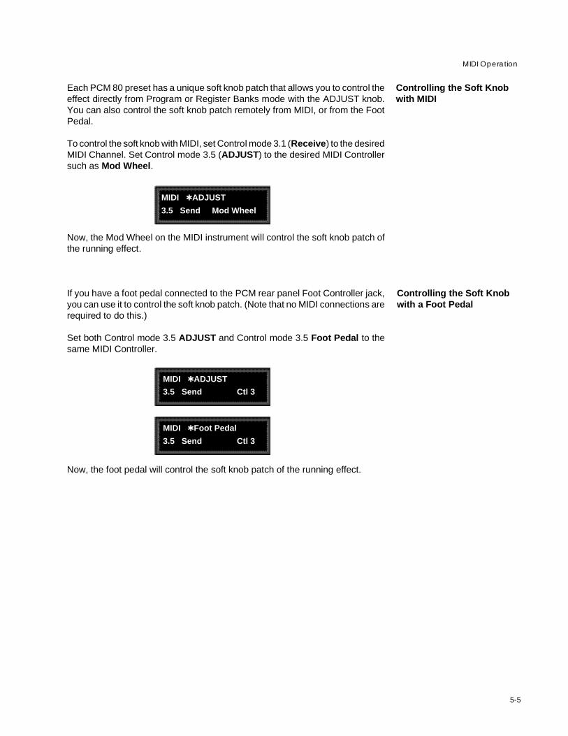
5-5
MIDI Operation
Each PCM 80 preset has a unique soft knob patch that allows you to control theeffect directly from Program or Register Banks mode with the ADJUST knob.You can also control the soft knob patch remotely from MIDI, or from the FootPedal.
To control the soft knob with MIDI, set Control mode 3.1 (Receive) to the desiredMIDI Channel. Set Control mode 3.5 (ADJUST) to the desired MIDI Controllersuch as Mod Wheel.
Controlling the Soft Knobwith MIDI
MIDI ADJUST
3.5 Send Mod Wheel
Now, the Mod Wheel on the MIDI instrument will control the soft knob patch ofthe running effect.
If you have a foot pedal connected to the PCM rear panel Foot Controller jack,you can use it to control the soft knob patch. (Note that no MIDI connections arerequired to do this.)
Set both Control mode 3.5 ADJUST and Control mode 3.5 Foot Pedal to thesame MIDI Controller.
Controlling the Soft Knobwith a Foot Pedal
MIDI ADJUST
3.5 Send Ctl 3
MIDI Foot Pedal
3.5 Send Ctl 3
Now, the foot pedal will control the soft knob patch of the running effect.

Lexicon
5-6
PCM 80 User Guide
Reception of MIDI Program Change and Bank Select messages can beselectively enabled/disabled from Control Mode parameter 3.0, MIDI PgmChange. The manner in which the PCM 80 interprets these messages isdetermined by the value of this parameter as follows:
Pgm Change: OffAll Program Change and Bank select messages are ignored. Pgm+ and Pgm–will load the next higher or lower program in the current bank.
Pgm Change : OnProgram Change messages 0-49 correspond to PCM 80 Effects 0.0 -4.9 in thecurrent bank. Program Change messages 50—127 are ignored. Pgm+ andPgm– will load the next higher or lower program in the current bank.
The current bank can be changed with MIDI Bank Select Messages as follows:
0-3: Program Banks 0-34: Internal Register Bank
5-9: reserved10-56: Memory Card Banks
The number of banks available on a given card will vary with cardsize as follows:
Card Size # Banks
64 2256 11512 23
1 Meg 47
Pgm Change: MapProgram Change 0-127 can be mapped to any PCM 80 Effect in any internal orcard bank. Two 128 element maps are stored internally, additional maps may bestored on RAM cards.
Map 0 Map 1
MIDI 0 = P0 0.0 MIDI 0 = P2 2.8MIDI 127 = P2 2.7 MIDI 127 = R 4.9
Pgm+ and Pgm– will load the next higher or lower program in the map.
Pgm Change: ChainAny Program Change number can be selected to load any one of ten customizedeffect “chains.” Once a chain is loaded, effects in the chain are accessed by thecontroller patched to Pgm + and Pgm – (program increment and programdecrement).
Program ChangeMessages

5-7
MIDI Operation
AutomationSysEx AutomationThe PCM 80 will transmit SysEx automation messages when Control Mode parameter 3.4, MIDI Automation is set to On. All changes made by front panel operations are transmitted as PCM 80 SysEx messages. This is intended primarily for use by editor programs and in configurations where it is desirablefor one or more PCM 80s to be client to a single PCM 80 acting as a Host. The current mode (Program Banks, Register Banks, Edit, Control or Tempo) ofthe Client does not follow the Host, but the actual parameter values do. (SysEx automation can also be stored on a sequencer and replayed in real-time. As a general rule, automating more than two or three SysEx program changes at once is not receommended.)
The PCM 80 can receive SysEx messages when Control mode 3.7 MIDI SysEx is set to Receive On. Note that when using SysEx automation, the device of the receiving PCM 80 must match the Target ID of the transmitting PCM 80.
The Target ID setting can be adjusted fropm Control 3.4 MIDI Automation. It is selected by pressing Load/ after setting Automation to On. The default setting for the Target ID is All.
The Device ID setting can be adjusted from Control mode 3.7 MIDI SysEx. It is selected by pressing Load/ after setting SysEx to Receive On. The default setting for the Device ID is 0.
Controller AutomationFor applications where it is desirable to "automate" changes made to PCM 80 effects with its own controls ( ADJUST knob, Foot Pedal, Footswitch 1 or Footswitch 2), we recommend assigning the controllers to MIDI destinations and recording the changes with a MIDI sequencer (see Control Mode parameter 3.5, MIDI Destinations).
Reset All ControllersThe PCM 80 recognizes the “Reset All Controllers” message. When received, all patched parameters are reset to their stored values. Patched parameters may also be reset from the PCM 80 front panel —Control Mode parameter 3.0 (the message will be transmitted from the PCM 80 as well).
MIDI Clock and Clock CommandsThe PCM 80 recognizes MIDI clock messages when Tempo Mode parameter 0.2, Tempo Source is set to MIDI. Any Delay or LFO parameter set to display tempo values will be synchronized to the tempo of the incoming MIDI clock.
MIDI Clock and Clock Commands are also available as Dynamic MIDI patch sources. The value of MIDI Clock when used as a patch source is a linear scaling of 0 to 127 (0 = 40 BPM and 127 = 400 BPM). The value of Clock Commands when used as a Dynamic MIDI patch source is 1 for START and CONTINUE and 0 for STOP.

Lexicon
5-8
PCM 80 User Guide
Dynamic MIDIThe following MIDI messages are available as Dynamic MIDI patch sources:
MIDI Controllers 1-119Pitch BendAfter Touch (Polyphonic and Channel combined)Velocity (Note On)Last NoteLow NoteHigh NoteTempo (40–400BPM is converted to controller range 0-127)Clock Commands
These MIDI messages are also available as threshold sources for severalModulation parameters: AR Env, Latch, Sw 1 and Sw 2. They may also be usedas a tap source for controlling Tempo.
MIDI Implementation Details, including System Exclusive documentation, areavailable to assist experienced programmers in developing software for usewith the PCM 80. These can be obtained directly from Lexicon.
Request: PCM 80 MIDI Implementation Details.
Bulk Data Dumps Control mode 3.8 (MIDI Dump) allows selection of the following types of bulkdata to be dumped directly from the PCM 80 to another PCM 80, or to editor/librarian software.
Displayed Name Description
CurrentPgm Currently running effectBank R Internal Register BankBank C0-CK Card Banks (card must be inserted)Map 0, 1 Internal Program Change MapsMap 2-33 Card Program Change Maps (card must be inserted)Chain 0-9 Internal Program ChainsChain 10-19 Card Program Chains (card must be inserted)Int Chains All Internal Program ChainsExt Chains All Card Program Chains (card must be inserted)Setup C Current SetupSetup 0-4 Internal SetupsSetup 5-9 Card Setups
Use ADJUST to select the bulk data type. Press Store to transmit the data .
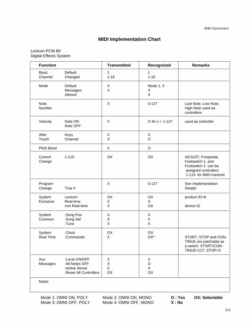
5-9
MIDI Operation
MIDI Implementation Chart
Mode 1: OMNI ON, POLY Mode 2: OMNI ON, MONO O : Yes OX: SelectableMode 3: OMNI OFF, POLY Mode 4: OMNI OFF, MONO X : No
Lexicon PCM 80Digital Effects System
Function Transmitted Recognized Remarks
Basic Default 1 1Channel Changed 1-16 1-16
Mode Default X Mode 1, 3Messages X XAltered X
Note X 0-127 Last Note, Low Note,Number High Note used as
controllers
Velocity Note ON X O 9n v = 1-127 used as controllerNote OFF
After Keys X XTouch Channel X O
Pitch Bend X O
Control 1-119 OX OX ADJUST, Footpedal,Change Footswitch 1, and
Footswitch 2 can be assigned controllers 1-119 for MIDI transmit
Program X 0-127 See ImplementationChange True # Details
System Lexicon OX OX product ID=6Exclusive Real-time X X
non Real-time X OX device ID
System :Song Pos X XCommon :Song Sel X X
:Tune X X
System :Clock OX OXReal Time :Commands X OX* START, STOP and CON-
TINUE are patchable asa switch: START/CON-TINUE=127; STOP=0
Aux :Local ON/OFF X XMessages :All Notes OFF X O
:Active Sense X X:Reset All Controllers OX OX
Notes

Lexicon
5-10
PCM 80 User Guide
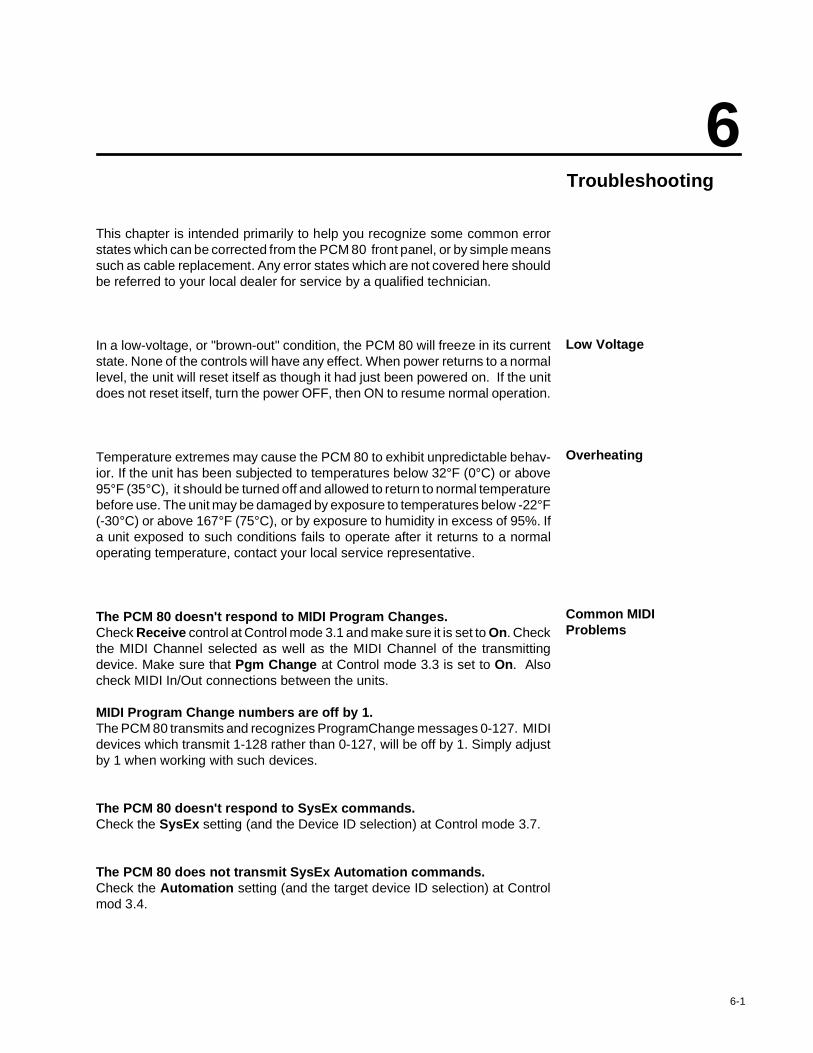
6-1
Troubleshooting
6Troubleshooting
This chapter is intended primarily to help you recognize some common errorstates which can be corrected from the PCM 80 front panel, or by simple meanssuch as cable replacement. Any error states which are not covered here shouldbe referred to your local dealer for service by a qualified technician.
In a low-voltage, or "brown-out" condition, the PCM 80 will freeze in its currentstate. None of the controls will have any effect. When power returns to a normallevel, the unit will reset itself as though it had just been powered on. If the unitdoes not reset itself, turn the power OFF, then ON to resume normal operation.
Temperature extremes may cause the PCM 80 to exhibit unpredictable behav-ior. If the unit has been subjected to temperatures below 32°F (0°C) or above95°F (35°C), it should be turned off and allowed to return to normal temperaturebefore use. The unit may be damaged by exposure to temperatures below -22°F(-30°C) or above 167°F (75°C), or by exposure to humidity in excess of 95%. Ifa unit exposed to such conditions fails to operate after it returns to a normaloperating temperature, contact your local service representative.
The PCM 80 doesn't respond to MIDI Program Changes.Check Receive control at Control mode 3.1 and make sure it is set to On. Checkthe MIDI Channel selected as well as the MIDI Channel of the transmittingdevice. Make sure that Pgm Change at Control mode 3.3 is set to On. Alsocheck MIDI In/Out connections between the units.
MIDI Program Change numbers are off by 1.The PCM 80 transmits and recognizes ProgramChange messages 0-127. MIDIdevices which transmit 1-128 rather than 0-127, will be off by 1. Simply adjustby 1 when working with such devices.
The PCM 80 doesn't respond to SysEx commands.Check the SysEx setting (and the Device ID selection) at Control mode 3.7.
The PCM 80 does not transmit SysEx Automation commands.Check the Automation setting (and the target device ID selection) at Controlmod 3.4.
Low Voltage
Overheating
Common MIDIProblems

6-2
LexiconPCM 80 User Guide
Operational Problems The PCM 80 will not lock onto an incoming digital signal.Check the cables that you are using. DO NOT USE ANALOG AUDIO CABLE TOCONNECT DIGITAL AUDIO.
Also check to make sure that your input signal complies with S/PDIF formatstandards. The PCM 80 will recognize AES professional format signals from anappropriate connector, but will not necessarily read and transmit encodedinformation accurately.
No Digital Audio OutputCheck the Analog Lvl and Digital Lvl controls at Control mode 0.1 and 0.2.
No Effects Output
Power On Behavior Check the setting of Mix Mode at Control mode 1.1. Also verify that anycontrollers patched to FX Lvl, Input Level, or Mix are not turned off.
The PCM 80 performs a series of self tests each time it is powered on, thendisplays the PCM 80 copyright notice. This should be followed by the display andloading of the last loaded effect. If this sequence does not occur, contact LexiconCustomer Service.

6-3
Troubleshooting
You can restore the PCM 80 to its default state without erasing registers byrestoring the factory default setup:
1. Press Control.
2. Use the Up and Down buttons to locate Row 4 Setup.
3. Turn SELECT to 4.1 Load.
4. Turn ADJUST counterclockwise to select "Factory Settings".
5. Press Load/. The PCM 80 will display the message "Setup restored".
The following table shows the parameters which comprise a setup, along withthe factory default setting of each parameter.
Control ModeMatrix Location System Parameter Default Setting
Audio 0.0 Word Clock Internal 48kHz0.1 Analog Lvl 100%0.2 Digital Lvl 0%0.3 Auto Lock Off0.4 SCMS Multi Copy0.5 Emphasis Bit Pass Thru0.6 Output Level +4dBu
System 1.0 Edit Mode Go1.1 Mix Mode Pgm
Global Mix Value 100% Wet1.2 Tempo Mode Pgm
Global Tempo Value 120 BPM1.3 Bypass Mode InputMute
Bypass Src Off1.4 Pgm Bypass AllMute1.5 Mem Protect On1.6 Auto Load Off1.7 Patch Update Delayed
MIDI 3.1 Receive OMNI3.2 Transmit 13.3 Pgm Change On
Pgm+ OffPgm– OffMap select 0Chain MIDI
3.4 Automation Off3.5 Footpedal None
Sw 1 NoneSw 2 NoneADJUST None
3.6 Int Clock Off3.7 SysEx On
Device ID 03.9 Dump Speed Slow
Tempo ModeMatrix Location System Parameter Default Setting
Tempo 0.2 Source Internal
Tap 1.3 Display On
Restoring FactoryDefault Settings

6-4
LexiconPCM 80 User Guide
ReinitializationReinitializing will erase all registers and setups
The following procedure will return the PCM 80 to the state it was in whenshipped from the factory. This includes erasing all registers and setups, as wellas restoring all of the default settings:
1. Press Control.
2. Use the Up and Down buttons to locate Row 1 System.
3. Turn SELECT to 1.8 Initialize.
4. Press Store. The PCM 80 will display the message "Are you sure? (PressSTORE).
If you don't want to reinitialize your unit, press any button except Store toreturn to matrix position 1.8.
If you press Store in response to this message, the display will flash"Restoring original factory settings" and your unit will be reinitialized.

7-1
Specifications
7PCM 80Specifications
Audio Input Connectors: Combined 3 pole XLR and 1/4 inch T/R/S phone jacks (2)Impedance: 0 dB/BAL switch position: 100kΩ, balanced
-20 dB/UNBAL switch position: 50kΩ, unbalancedA/D DynamicRange: 100 dB 1 kHz, signal present, unweightedLevels: 0 dB/BAL switch position: -2 dBu min for full scale, +20 dBu max
-20 dB/UNBAL switch position: -22 dBu min for full scale, 0 dBu maxCMRR: 0 dB/BAL switch position: 40 dB minimum, 10 Hz to 20 kHz
Audio Output Connectors: 1/4 inch T/R/S phone jacks (2); balanced XLRs, pin 2 "high" (2)Impedance: 125Ω, each side, balancedD/A DynamicRange: 95 dB 1 kHz, signal present, unweightedLevels: +18 dBm max, full scale (+4 dBu setting) balanced, unbalanced
+4 dBm max, full scale (-10 dBu setting)Protection: Relays provided for output muting during power on/off
A/D Performance FrequencyResponse: 10 Hz to 20 kHz, ±0.5 dBCrosstalk: -65 dB max, 10 Hz to 20 kHzS/N Ratio: 100 dB min, 20 kHz bandwidthTHD: 0.004% max, 10 Hz to 20 kHzDynamicRange: >100 dB, 20 kHz bandwidthDelay: 24 samples (0.54 msec for 44.1 kHz, 0.50 msec for 48 kHz)
D/A Performance FrequencyResponse: 10 Hz to 20 kHz, ±0.5 dBCrosstalk: -80 dB max, 10 Hz to 20 kHzS/N Ratio: 100 dB min, 20 kHz bandwidthTHD: 0.006% max, 10 Hz to 20 kHzDynamicRange: >95 dB, 20 kHz bandwidthDelay: 50 samples (1.13 msec for 44.1 kHz, 1.04 msec for 48 kHz)
A/A Performance FrequencyResponse: 10 Hz to 20 kHz, ±0.5 dBCrosstalk: -55 dB max, 10 Hz to 20 kHzS/N Ratio: 90 dB min, 20 kHz bandwidthTHD: 0.008% max, 10 Hz to 20 kHzDynamicRange: >94 dB, 20 kHz bandwidth, >92 dB per AES-17 section 7.3

Lexicon
7-2
PCM 80 User Guide
Digital Audio Interface Connectors: Coaxial, RCA typeFormat: conforms to S/PDIF IEC-958 consumer standardsSample Rates: 44.1 kHz, 48 kHz
Internal Audio Data Paths Conversion: 18 bitsDSP: 18 to 24 bits
Audio Memory Configuration Base memory: Two 256k x 18 DRAMsUserExpansion: Two SIMM sockets provided for either 1 Meg x 9,
4 Meg x 9 or 16 Meg x 9, 70 nsec DRAM modules
External Memory Card Connector: Accepts PCMCIA Type I cards, 68 pinsStandards: Conforms to PCMCIA 2.0 / JEIDA 4.0Card Format: Supports up to 1MB SRAM (attribute memory not required)
Control Interface MIDI: 5-pin DIN connectors provided for MIDI IN, THRU, & OUTFootswitch: 1/4 inch T/R/S phone jack provided for
2 independent momentary footswitchesSystem detects normal-open, or normal-closed on power up
Foot controller: 1/4 inch T/R/S phone jack provided for footpedal(100Ω minimum, 10kΩ maximum impedance)
General Dimensions: 19.0"W x 1.75"H x 12.0"D (483 x 45 x 305 mm)19 inch rack mount standard, 1U high
Weight: Net: 6.4 lbs (2.9 kg)Shipping: 9.5 lbs (4.3 kg)
PowerRequirements: 100-240 VAC, 50-60 Hz, 35 W, 3-pin IEC power connectorRFI/ESD: Conforms to FCC Class B,
EN55022 Class B (CE), IEC 801-2, IEC 801-3Environment: Operating temperature: 32˚ to 104˚F (0˚ to 40˚C)
Storage temperature: -22˚ to 167˚F (-30˚ to 70˚C)Humidity: maximum 95% without condensation
Unless otherwise noted, all audio specifications assume rear-panel switch set to BAL, input level controlis set for unity gain (0dB), and analog I/O connections wired for balanced configuration.
Specifications subject to change without notice.

Lexicon Part # 070-11263 Rev 1
Lexicon Inc.3 Oak ParkBedford MA 01730-1441Telephone 781-280-0300Fax 781-280-0490