pcplug-u - communication protocol
TRANSCRIPT

PcPlug-U
USB Communication Interface
(rev.03 – 11-07-2019)
LaserPoint srl – Via Burona, 51 – 20090 Vimodrone (Milano) – Italy
Phone +39 02 27 400 236 – Fax +39 02 25 029 161 www.laserpoint.eu

LaserPoint s.r.l. – PcPlug-U communication interface 2
Table of Contents:
1. Install..................................................................................................................... 3
2. Set Up the Communication: ............................................................................. 3
3. Commands and Answers Formatting: ............................................................ 4
3.1 Command format .............................................................................................................. 4
3.2 Answer format ................................................................................................................... 4
3.3 Error Message .................................................................................................................... 4
4. Product Series and associated Command Tables. ........................................ 5
5. Commands and Answer Tables for Product Series #1 ............................... 6
5.1 Information commands .................................................................................................... 6
5.2 Measurement setup commands ...................................................................................... 7
5.3 Gain and Full Scale Commands ...................................................................................... 7
5.4 Wavelength setup commands ......................................................................................... 8
5.5 Measurement acquisition commands ............................................................................ 9
6. Commands and Answer Tables for Product Series #2 ............................. 10
6.1 Information commands .................................................................................................. 10
6.2 Measurement setup commands .................................................................................... 11
6.3 Gain and Full Scale Commands .................................................................................... 12
6.4 Wavelength setup commands ....................................................................................... 12
6.5 Measurement acquisition commands .......................................................................... 13
7. Commands and Answer Tables for Product Series #3 ............................. 14
7.1 Information commands .................................................................................................. 14
7.2 Measurement setup commands .................................................................................... 15
7.3 KEFUN=0-1-2-3-4 Gain and Full Scale Commands ................................................... 15
7.4 Wavelength setup commands ....................................................................................... 16
7.5 Measurement acquisition commands .......................................................................... 16
8. Examples and Notes ......................................................................................... 18
8.1 EXAMPLE 1 – quick communication test .................................................................... 18
8.2 EXAMPLE 2 – opening the communication using FTDXX functions ..................... 18
8.3 EXAMPLE 3 – command sequence to perform an energy measure ........................ 19
8.4 EXAMPLE 4 – command sequence to perform a power measure ........................... 20
9. Annex 1 – FTD2XX.DLL Dynamic Library .................................................. 21
9.1 D2XX Driver Architecture ............................................................................................. 21
9.2 Useful links for FTDI drivers and libraries: ................................................................ 22
9.3 DLL Functions ................................................................................................................. 22

LaserPoint s.r.l. – PcPlug-U communication interface 3
1. INSTALL
Connect the PcPlug-U electronics through the USB port to the host PC.
Follow the prompt to install the USB drivers. They will be automatically installed through Windows update automatic
download, or manually installed by using the driver installers available on the provided USB flash drive: inside the USB
flash folder
X:\DRIVER\
you can find the driver installers for both 64 and 32 bit PCs:
\dpinst_amd64.exe
\dpinst_x86.exe
2. SET UP THE COMMUNICATION:
The PcPlug-U employs an FTDI FT232RQ chip that is a USB to serial UART interface.
This means that, for the host PC and for the user, this device will appear like a true COM port.
Example:
The COM number associated to this device can be known using WindowsTM “Device Manager” panel.
And any serial terminal software (like WindowsTM HyperTerminal) can be used to open and test the communication
with this device. See Chapter 8.1 for the example
These are the communication parameters that must be used:
Baud Rate: For product Series #2 and #3: 38400 bps
For product Series #1: 9600 kbps
(See chapter 4 for part number lists)
Parity: no
Data Bits: 8
Stop Bits: 1
When writing your Code, include the FTD2XX.DLL Dynamic Library for Windows in order to write your application.
This library provides useful functions to recognize and set up the communication with the PcPlug-U device.
Please see the FTD2XX.DLL complete manual on FTDI website, or refer to the extract we included in Annex 1 at the
end of this paper.

LaserPoint s.r.l. – PcPlug-U communication interface 4
3. COMMANDS AND ANSWERS FORMATTING:
When the PcPlug-U receives a valid input command, it confirms to the host device that the command has been
received and return an answer. The Commands and Answers are ASCII formatted.
3.1 Command format
The format of a valid command is: *COMMANDNAME:
where:
“*” Start of command
“COMMANDNAME” The command instruction is a sequence of ASCII characters. It must be in capitals.
Each command is described in the following pages.
“:” End of command
3.2 Answer format
When the PcPlug-U receives a valid Input Command it replies sending a message through the USB interface.
The format of an answer is: #ANSWER;
where:
“#” Start of answer
“ANSWER” there are three kind of answer:
• String: ASCII character sequence
• Int: integer number, numerical sequence (in ASCII code)
• Float: floating point number, numerical sequence plus decimal point (in ASCII
code)
“;” End of answer
Please note that maximum response time from PcPlug-U is ~50msec. It’s therefore recommended to set a delay of
50ms between write and read function.
3.3 Error Message
When the PcPlug-U receives an invalid command or a command affected by communication errors the answer is
“??;”
where:
“??” USB communication error
“;” End of answer
Common reasons of error message are:
Input command not started with * character
Input command not in capitals
Input command does not correspond with the command list
LaserPoint s.r.l. – PcPlug-U communication interface 5
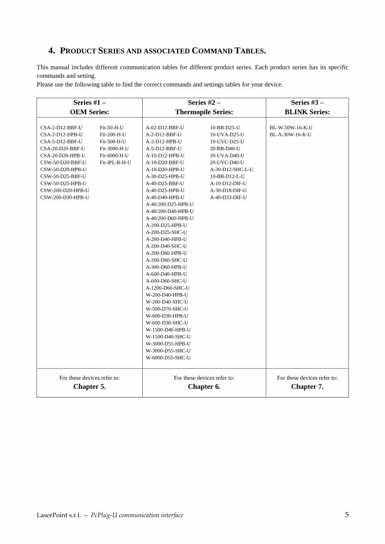
4. PRODUCT SERIES AND ASSOCIATED COMMAND TABLES.
This manual includes different communication tables for different product series. Each product series has its specific
commands and setting.
Please use the following table to find the correct commands and settings tables for your device.
Series #1 –
OEM Series:
Series #2 –
Thermopile Series:
Series #3 –
BLINK Series:
CSA-2-D12-BBF-U
CSA-2-D12-HPB-U
CSA-5-D12-BBF-U
CSA-20-D20-BBF-U
CSA-20-D20-HPB-U
CSW-50-D20-BBF-U
CSW-50-D20-HPB-U
CSW-50-D25-BBF-U
CSW-50-D25-HPB-U
CSW-200-D20-HPB-U
CSW-200-D30-HPB-U
Fit-50-H-U
Fit-200-H-U
Fit-500-H-U
Fit-3000-H-U
Fit-6000-H-U
Fit-IPL-R-H-U
A-02-D12-BBF-U
A-2-D12-BBF-U
A-2-D12-HPB-U
A-5-D12-BBF-U
A-10-D12-HPB-U
A-10-D20-BBF-U
A-10-D20-HPB-U
A-30-D25-HPB-U
A-40-D25-BBF-U
A-40-D25-HPB-U
A-40-D40-HPB-U
A-40/200-D25-HPB-U
A-40/200-D40-HPB-U
A-40/200-D60-HPB-U
A-200-D25-HPB-U
A-200-D25-SHC-U
A-200-D40-HPB-U
A-200-D40-SHC-U
A-200-D60-HPB-U
A-200-D60-SHC-U
A-300-D60-HPB-U
A-600-D40-HPB-U
A-600-D60-SHC-U
A-1200-D60-SHC-U
W-200-D40-HPB-U
W-200-D40-SHC-U
W-500-D70-SHC-U
W-600-D30-HPB-U
W-600-D30-SHC-U
W-1500-D40-HPB-U
W-1500-D40-SHC-U
W-3000-D55-HPB-U
W-3000-D55-SHC-U
W-6000-D55-SHC-U
10-BB-D25-U
10-UVA-D25-U
10-UVC-D25-U
20-BB-D40-U
20-UVA-D40-U
20-UVC-D40-U
A-30-D12-SHC-L-U
10-BB-D12-L-U
A-10-D12-DIF-U
A-30-D18-DIF-U
A-40-D33-DIF-U
BL-W-50W-16-K-U
BL-A-30W-16-K-U
For these devices refer to:
Chapter 5.
For these devices refer to:
Chapter 6.
For these devices refer to:
Chapter 7.

LaserPoint s.r.l. – PcPlug-U communication interface 6
5. COMMANDS AND ANSWER TABLES FOR PRODUCT SERIES #1
This product series includes these products:
Series #1 – OEM Series
CSA-2-D12-BBF-U
CSA-2-D12-HPB-U
CSA-5-D12-BBF-U
CSA-20-D20-BBF-U
CSA-20-D20-HPB-U
CSW-50-D20-BBF-U
CSW-50-D20-HPB-U
CSW-50-D25-BBF-U
CSW-50-D25-HPB-U
CSW-200-D20-HPB-U
CSW-200-D30-HPB-U
Fit-50-H-U
Fit-200-H-U
Fit-500-H-U
Fit-3000-H-U
Fit-6000-H-U
Fit-IPL-R-H-U
5.1 Information commands
These commands are used to get ID information about the PcPlug-U and the sensor. This info may be useful when
asking Laserpoint for support.
Command Answer (example) Description
HEADN “H” + String 8 char Displays the Sensor Head model name (shortened)
SERNU “S” + Int 6 digit Displays the Sensor Head serial number
FHV “H” + 2 char + “F” + 4
char
Displays the PcPlug-U Electronics Hardware and Firmware
version
KEFUN “K” + Int 2 digit This 2 digit code number identifies the sensor type and the
available functionalities.
For this series of devices, the answer will be one among the
highlighted:
00 = OEM Thermopile sensor - Power
01 = OEM Thermopile sensor - Fit Mode
02 = OEM Thermopile sensor - Energy
03 = OEM Thermopile sensor - Power + Energy
04 = OEM Thermopile sensor - Fit Mode + Energy
05 = Thermopile sensor – Power (see chapter 6)
06 = Thermopile sensor – Power + Energy (see chapter 6)
07 = Thermopile sensor – Fit mode (see chapter 6)
08 = Thermopile sensor – Fit mode + Energy (see chapter 6)
09 = Photodiode sensor
10 = NA
11 = NA
12 = Blink Series Sensor - Power (see chapter 7)
13 = Blink Series Sensor - Power + Energy (see chapter 7)

LaserPoint s.r.l. – PcPlug-U communication interface 7
5.2 Measurement setup commands
These commands are used for the initial set up: operation mode selection (Power, Energy, others) and a reset of zero.
Command Answer (example) Description
POWER “ok” or
“NA” (if not available)
Set PcPlug-U in Power Meter mode (if available)
ENERGY “ok” or
“NA” (if not available)
Set PcPlug-U in Energy operation mode (if available)
ZERO “ok” Perform a Zero.
This action will take about 3 seconds, and will reset the zero
value of the sensor.
Please make sure that this action is performed only when the
sensor is not hit by laser or any other thermal source.
FAST “FAST” This is the default setting.
It enables the acceleration algorithm, granting a faster
response time.
SLOW “SLOW” Disables the acceleration algorithm.
The response time may be dramatically lowered, but also noise
(from laser source, or from cooling, or from environment) can
be mitigated.
FASTSLOW “FAST” or
“SLOW”
Returns the Fast/Slow current setting
5.3 Gain and Full Scale Commands
These commands allow selection of electronic amplifier gain (or in other words the selection of a Full Scale Range).
Command Answer (example) Description
SETX1 0 “ok”
“NA” (if not available)
Set the 0th electronic amplifier gain (gain x1) (bigger full scale)
SETX1 1 “ok”
“NA” (if not available)
Set the 1st electronic amplifier gain (gain x10) (smaller full scale)
X1D Int 1 digit, 0 or 1 Displays the currently selected electronic amplifier gain:
0: x1 gain
1: x10 gain

LaserPoint s.r.l. – PcPlug-U communication interface 8
5.4 Wavelength setup commands
Command Answer (example) Description
LAMBDA “LAMBDA” + Int 1 digit
LAMBDA3
Displays the currently selected wavelength number.
From number 1 to 5.
SETLAM + Int 1 digit
SETLAM2
“ok” Select the wavelength number.
From number 1 to 5.
NOML1 String 3 char
CO2
Displays wavelength 1 Label
NOML2 String 3 char
YAG
Displays wavelength 2 Label
NOML3 String 3 char
LDS
Displays wavelength 3 Label
NOML4 String 3 char
VIS
Displays wavelength 4 Label
NOML5 String 3 char
EXC
Displays wavelength 5 Label
CFWL1 Float 2int.3dec
00.000
Displays the spectral correction coefficient of wavelength 1.
If the value is 00.000 it means that this wavelength is not
available.
CFWL2 Float 2int.3dec
01.000
Displays the spectral correction coefficient of wavelength 2.
If the value is 00.000 it means that this wavelength is not
available.
CFWL3 Float 2int.3dec
00.950
Displays the spectral correction coefficient of wavelength 3.
If the value is 00.000 it means that this wavelength is not
available.
CFWL4 Float 2int.3dec
00.990
Displays the spectral correction coefficient of wavelength 4.
If the value is 00.000 it means that this wavelength is not
available.
CFWL5 Float 2int.3dec
00.000
Displays the spectral correction coefficient of wavelength 5.
If the value is 00.000 it means that this wavelength is not
available.
NOTE: in order to choose the correct wavelength is recommended to use all the NOMLx and CFWLx commands, so you
can know which wavelengths are available (if CFWL answer ≠ 0) or not available (if CFWL answer = 0).

LaserPoint s.r.l. – PcPlug-U communication interface 9
5.5 Measurement acquisition commands
Command Answer (example) Description
OUTPM Float
4.325
Displays measured power (W).
The answer is formatted according to VISCA command.
VISCA Int 1 digit This command is used to know the measured number format
and Unit of measure:
0 = unit of measure W (or J) – no decimal number
1 = unit of measure W (or J) – one decimal number
2 = unit of measure W (or J) – two decimal number
3 = unit of measure mW (or mJ) – no decimal number
4 = unit of measure mW (or mJ) – one decimal number
5 = unit of measure mW (or mJ) – two decimal number
6 = unit of measure W (or J) – no decimal number (steps of 5W
or 10W depending on sensor and gain)
STATUS Int 3 digits
114
Displays status byte.
Notice that this 3 digit integer must be converted into binary.
bit 0: arm/zeroing done; (1) yes, (0) no
bit 1: measure running; (1) yes, (0) no
bit 2: Head connected; (1) yes, (0) no
bit 3: cool alarm running; (1) yes, (0) no
bit 4: wait before start a new measure; (1) yes
bit 5: not used; default value (0)
bit 6: overflow alarm; (1) yes, (0) no
bit 7: thermistor connected; (1) yes, (0) no
TERMI Int 1 digit Thermistor availability: (1) yes, (0) no
If thermistor is available the temperature
TEMP Int 3 digit
255
Displays Head temperature x 10 (°C)
LaserPoint s.r.l. – PcPlug-U communication interface 10
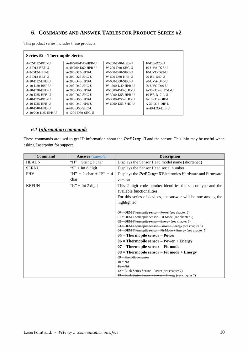
6. COMMANDS AND ANSWER TABLES FOR PRODUCT SERIES #2
This product series includes these products:
Series #2 - Thermopile Series
A-02-D12-BBF-U
A-2-D12-BBF-U
A-2-D12-HPB-U
A-5-D12-BBF-U
A-10-D12-HPB-U
A-10-D20-BBF-U
A-10-D20-HPB-U
A-30-D25-HPB-U
A-40-D25-BBF-U
A-40-D25-HPB-U
A-40-D40-HPB-U
A-40/200-D25-HPB-U
A-40/200-D40-HPB-U
A-40/200-D60-HPB-U
A-200-D25-HPB-U
A-200-D25-SHC-U
A-200-D40-HPB-U
A-200-D40-SHC-U
A-200-D60-HPB-U
A-200-D60-SHC-U
A-300-D60-HPB-U
A-600-D40-HPB-U
A-600-D60-SHC-U
A-1200-D60-SHC-U
W-200-D40-HPB-U
W-200-D40-SHC-U
W-500-D70-SHC-U
W-600-D30-HPB-U
W-600-D30-SHC-U
W-1500-D40-HPB-U
W-1500-D40-SHC-U
W-3000-D55-HPB-U
W-3000-D55-SHC-U
W-6000-D55-SHC-U
10-BB-D25-U
10-UVA-D25-U
10-UVC-D25-U
20-BB-D40-U
20-UVA-D40-U
20-UVC-D40-U
A-30-D12-SHC-L-U
10-BB-D12-L-U
A-10-D12-DIF-U
A-30-D18-DIF-U
A-40-D33-DIF-U
6.1 Information commands
These commands are used to get ID information about the PcPlug-U and the sensor. This info may be useful when
asking Laserpoint for support.
Command Answer (example) Description
HEADN “H” + String 8 char Displays the Sensor Head model name (shortened)
SERNU “S” + Int 6 digit Displays the Sensor Head serial number
FHV “H” + 2 char + “F” + 4
char
Displays the PcPlug-U Electronics Hardware and Firmware
version
KEFUN “K” + Int 2 digit This 2 digit code number identifies the sensor type and the
available functionalities.
For this series of devices, the answer will be one among the
highlighted:
00 = OEM Thermopile sensor - Power (see chapter 5)
01 = OEM Thermopile sensor - Fit Mode (see chapter 5)
02 = OEM Thermopile sensor - Energy (see chapter 5)
03 = OEM Thermopile sensor - Power + Energy (see chapter 5)
04 = OEM Thermopile sensor - Fit Mode + Energy (see chapter 5)
05 = Thermopile sensor – Power
06 = Thermopile sensor – Power + Energy
07 = Thermopile sensor – Fit mode
08 = Thermopile sensor – Fit mode + Energy
09 = Photodiode sensor
10 = NA
11 = NA
12 = Blink Series Sensor - Power (see chapter 7)
13 = Blink Series Sensor - Power + Energy (see chapter 7)
LaserPoint s.r.l. – PcPlug-U communication interface 11
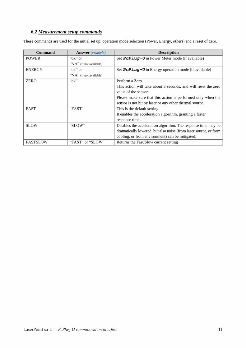
6.2 Measurement setup commands
These commands are used for the initial set up: operation mode selection (Power, Energy, others) and a reset of zero.
Command Answer (example) Description
POWER “ok” or
“NA” (if not available)
Set PcPlug-U in Power Meter mode (if available)
ENERGY “ok” or
“NA” (if not available)
Set PcPlug-U in Energy operation mode (if available)
ZERO “ok” Perform a Zero.
This action will take about 3 seconds, and will reset the zero
value of the sensor.
Please make sure that this action is performed only when the
sensor is not hit by laser or any other thermal source.
FAST “FAST” This is the default setting.
It enables the acceleration algorithm, granting a faster
response time.
SLOW “SLOW” Disables the acceleration algorithm. The response time may be
dramatically lowered, but also noise (from laser source, or from
cooling, or from environment) can be mitigated.
FASTSLOW “FAST” or “SLOW” Returns the Fast/Slow current setting
LaserPoint s.r.l. – PcPlug-U communication interface 12
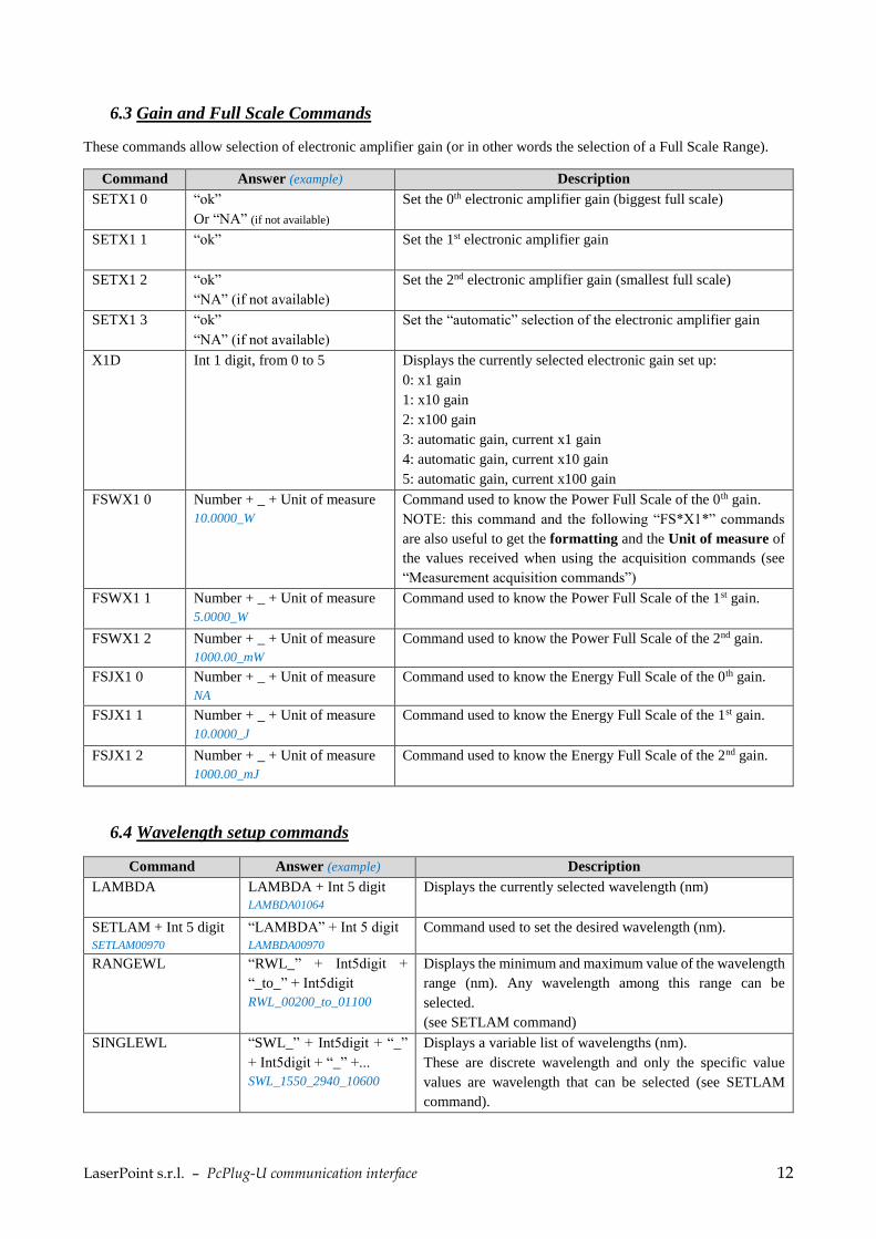
6.3 Gain and Full Scale Commands
These commands allow selection of electronic amplifier gain (or in other words the selection of a Full Scale Range).
Command Answer (example) Description
SETX1 0 “ok”
Or “NA” (if not available)
Set the 0th electronic amplifier gain (biggest full scale)
SETX1 1 “ok”
Set the 1st electronic amplifier gain
SETX1 2 “ok”
“NA” (if not available)
Set the 2nd electronic amplifier gain (smallest full scale)
SETX1 3 “ok”
“NA” (if not available)
Set the “automatic” selection of the electronic amplifier gain
X1D Int 1 digit, from 0 to 5 Displays the currently selected electronic gain set up:
0: x1 gain
1: x10 gain
2: x100 gain
3: automatic gain, current x1 gain
4: automatic gain, current x10 gain
5: automatic gain, current x100 gain
FSWX1 0 Number + _ + Unit of measure
10.0000_W
Command used to know the Power Full Scale of the 0th gain.
NOTE: this command and the following “FS*X1*” commands
are also useful to get the formatting and the Unit of measure of
the values received when using the acquisition commands (see
“Measurement acquisition commands”)
FSWX1 1 Number + _ + Unit of measure
5.0000_W
Command used to know the Power Full Scale of the 1st gain.
FSWX1 2 Number + _ + Unit of measure
1000.00_mW
Command used to know the Power Full Scale of the 2nd gain.
FSJX1 0 Number + _ + Unit of measure
NA
Command used to know the Energy Full Scale of the 0th gain.
FSJX1 1 Number + _ + Unit of measure
10.0000_J
Command used to know the Energy Full Scale of the 1st gain.
FSJX1 2 Number + _ + Unit of measure
1000.00_mJ
Command used to know the Energy Full Scale of the 2nd gain.
6.4 Wavelength setup commands
Command Answer (example) Description
LAMBDA LAMBDA + Int 5 digit
LAMBDA01064
Displays the currently selected wavelength (nm)
SETLAM + Int 5 digit
SETLAM00970
“LAMBDA” + Int 5 digit
LAMBDA00970
Command used to set the desired wavelength (nm).
RANGEWL “RWL_” + Int5digit +
“_to_” + Int5digit
RWL_00200_to_01100
Displays the minimum and maximum value of the wavelength
range (nm). Any wavelength among this range can be
selected.
(see SETLAM command)
SINGLEWL “SWL_” + Int5digit + “_”
+ Int5digit + “_” +...
SWL_1550_2940_10600
Displays a variable list of wavelengths (nm).
These are discrete wavelength and only the specific value
values are wavelength that can be selected (see SETLAM
command).

LaserPoint s.r.l. – PcPlug-U communication interface 13
6.5 Measurement acquisition commands
Command Answer (example) Description
OUTPM Float
4.325
Displays measured power value (or energy).
The number format varies depending on many parameters. To
know the number format of each scale, please use the “FS*X1
*” commands.
This is a “one command – one answer” command: each time
this command is sent, one one value is answered.
This command is used to request a few samples per seconds
(max 5-8 requests). For higher sampling it’s recommended to
use the OUTPTS command.
STATUS “Y” + Int 5 digits
Y00003
Displays the status byte.
Notice that this 5 digit integer must be converted into binary.
Bit 0: Head connected: (1) yes, (0) no
Bit 1: thermistor connected: (1) yes, (0) no
Bit 2: not used
Bit 3: cool warning (1)
Bit 4: battery: connected to AC (1)
Bit 5: battery: charge in progress (1)
Bit 6: overload warning (1)
Bit 7: overflow warning (1)
Bit 8: status “ready”, for Fit/Energy mode (1)
Bit 9: status “triggered”, for Fit/Energy mode (1)
Bit 10: status “wait”, for Fit modes (1)
Bit 11: not used
Bit 12: overflow ADC gain G=x1 (1)
Bit 13: overflow ADC gain G=x10 (1)
Bit 14: overflow ADC gain G=x100 (1)
Bit 15: not used
TERM “T” + Int 1 digit Thermistor availability: (1) yes, (0) no
TEMP “t” + Int 3 digit
t258
Displays Head temperature x 10 (°C)
OUTPTS Integer + “_” + Integer +
“_” + Integer
0.0994_00003_258
This command is used to get a continuous stream of measured
values (formatted like OUTPM command) + status byte
(formatted like STATUS) + sensor temperature (formatted like
TEMP).
It is used when power mode is selected and a continuous flow
of measurement is required.
The output is delivered at 8hz, meaning 125ms interval between
two measures.
LaserPoint s.r.l. – PcPlug-U communication interface 14
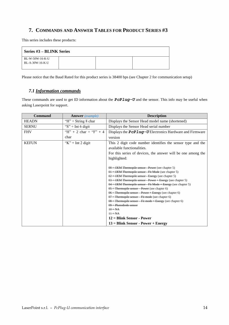
7. COMMANDS AND ANSWER TABLES FOR PRODUCT SERIES #3
This series includes these products:
Series #3 – BLINK Series
BL-W-50W-16-K-U
BL-A-30W-16-K-U
Please notice that the Baud Rated for this product series is 38400 bps (see Chapter 2 for communication setup)
7.1 Information commands
These commands are used to get ID information about the PcPlug-U and the sensor. This info may be useful when
asking Laserpoint for support.
Command Answer (example) Description
HEADN “H” + String 8 char Displays the Sensor Head model name (shortened)
SERNU “S” + Int 6 digit Displays the Sensor Head serial number
FHV “H” + 2 char + “F” + 4
char
Displays the PcPlug-U Electronics Hardware and Firmware
version
KEFUN “K” + Int 2 digit This 2 digit code number identifies the sensor type and the
available functionalities.
For this series of devices, the answer will be one among the
highlighted:
00 = OEM Thermopile sensor - Power (see chapter 5)
01 = OEM Thermopile sensor - Fit Mode (see chapter 5)
02 = OEM Thermopile sensor - Energy (see chapter 5)
03 = OEM Thermopile sensor - Power + Energy (see chapter 5)
04 = OEM Thermopile sensor - Fit Mode + Energy (see chapter 5)
05 = Thermopile sensor – Power (see chapter 6)
06 = Thermopile sensor – Power + Energy (see chapter 6)
07 = Thermopile sensor – Fit mode (see chapter 6)
08 = Thermopile sensor – Fit mode + Energy (see chapter 6)
09 = Photodiode sensor
10 = NA
11 = NA
12 = Blink Sensor - Power
13 = Blink Sensor - Power + Energy

LaserPoint s.r.l. – PcPlug-U communication interface 15
7.2 Measurement setup commands
These commands are used for the initial set up: operation mode selection (Power, Energy, others) and a reset of zero.
Command Answer (example) Description
POWER “ok” or
“NA” (if not available)
Set PcPlug-U in Power Meter mode (if available)
ENERGY “ok” or
“NA” (if not available)
Set PcPlug-U in Energy operation mode (if available)
ZERO “Zok” Perform a Zero.
This action will take about 3 seconds, and will reset the zero
value of the sensor.
Please make sure that this action is performed only when the
sensor is not hit by laser or any other thermal source.
FAST “FAST” This is the default setting.
It enables the acceleration algorithm, granting a faster
response time.
SLOW “SLOW” Disables the acceleration algorithm. The response time may be
dramatically lowered, but also noise (from laser source, or from
cooling, or from environment) can be mitigated.
FASTSLOW “FAST” or “SLOW” Returns the Fast/Slow current setting
7.3 KEFUN=0-1-2-3-4 Gain and Full Scale Commands
These commands allow selection of electronic amplifier gain (or in other words the selection of a Full Scale Range).
Command Answer (example) Description
SETX1 0 “ok”
“NA” (if not available)
Set the 0th electronic amplifier gain (biggest full scale)
SETX1 1 “ok”
or “NA” (if not available)
Set the 1st electronic amplifier gain
SETX1 2 “ok”
“NA” (if not available)
Set the 2nd electronic amplifier gain (smallest full scale)
SETX1 3 “ok”
“NA” (if not available)
Set the “automatic” selection of the electronic amplifier gain
X1D Int 1 digit, from 0 to 5 Displays the currently selected electronic gain set up:
0: x1 gain
1: x10 gain
2: x100 gain
3: automatic gain, current x1 gain
4: automatic gain, current x10 gain
5: automatic gain, current x100 gain
FSWX1 0 Number + _ + Unit of measure
10.0000_W
Command used to know the Power Full Scale of the 0th gain.
NOTE: this command and the following “FS*X1*” commands
are also useful to get the formatting and the Unit of measure of
the values received when using the acquisition commands (see
“Measurement acquisition commands”)
FSWX1 1 Number + _ + Unit of measure
5.0000_W
Command used to know the Power Full Scale of the 1st gain.
FSWX1 2 Number + _ + Unit of measure
1000.00_mW
Command used to know the Power Full Scale of the 2nd gain.
FSJX1 0 Number + _ + Unit of measure Command used to know the Energy Full Scale of the 0th gain.

LaserPoint s.r.l. – PcPlug-U communication interface 16
NA
FSJX1 1 Number + _ + Unit of measure
10.0000_J
Command used to know the Energy Full Scale of the 1st gain.
FSJX1 2 Number + _ + Unit of measure
1000.00_mJ
Command used to know the Energy Full Scale of the 2nd gain.
7.4 Wavelength setup commands
Command Answer (example) Description
LAMBDA LAMBDA + Int 5 digit
LAMBDA01064
Displays the currently selected wavelength (nm)
SETLAM + Int 5 digit
SETLAM00970
“LAMBDA” + Int 5 digit
LAMBDA00970
Command used to set the desired wavelength (nm).
RANGEWL “RWL_” + Int5digit +
“_to_” + Int5digit
RWL_00200_to_01100
Displays the minimum and maximum value of the available
wavelength range (nm). Any wavelength among this range
can be selected.
(see SETLAM command)
SINGLEWL “SWL_” + Int5digit + “_”
+ Int5digit + “_” +...
SWL_1550_2940_10600
Displays a variable list of available wavelengths (nm).
These are discrete wavelength and only the specific value
values are wavelength that can be selected
(see SETLAM command).
7.5 Measurement acquisition commands
Command Answer (example) Description
OUTPM Float
4.325
Displays measured power value (or energy).
The number format varies depending on many parameters. To
know the number format of each scale, please use the “FS*X1
*” commands.
This is a “one command – one answer” command: each time
this command is sent, one one value is answered.
This command is used to request a few samples per seconds
(max 5-8 requests). For higher sampling it’s recommended to
use the OUTPTS command.
OUTPTS 16 x [Integer + “_”] + “s”
+ 5 digit Integer + “t” + 3
digit Integer + “c” + 2
digit Integer
3.056_3.054_3.052_3.049_
3.047_3.045_3.043_3.041_
3.038_3.036_3.034_3.032_
3.030_3.028_3.026_3.025
s00003t251c49
This command is used to activate a continuous stream of
measured values. It is used when power mode is selected and a
continuous flow of measurement with high sampling rate is
required.
The answer is delivered 12 times per second in form a of a
string.
Each string contains:
16 measured values (formatted like OUTPM command) +
Status bytes (formatted like STATUS command) +
Sensor temperature (formatted like TEMP) +
2 digit counter (increasing from 00 to 99)
NOTE: The total number of values outputted per second is = 12
strings x 16 values = 192 samples
NOTE2: the counter that can be used to check if strings are
complete and/or if there is some string that is missing due to
communication errors.

LaserPoint s.r.l. – PcPlug-U communication interface 17
To stop the data stream use the command *COMMAND:
COMMAND “COMMAND” This command is used to stop any data stream mode that is
active.
STATUS “Y” + Int 5 digits
Y00003
Displays the status byte.
Notice that this 5 digit integer must be converted into binary.
Bit 0: Head connected: (1) yes, (0) no
Bit 1: thermistor connected: (1) yes, (0) no
Bit 2: not used
Bit 3: cool warning (1)
Bit 4: battery: connected to AC (1)
Bit 5: battery: charge in progress (1)
Bit 6: overload warning (1)
Bit 7: overflow warning (1)
Bit 8: status “ready”, for Fit/Energy mode (1)
Bit 9: status “triggered”, for Fit/Energy mode (1)
Bit 10: status “wait”, for Fit modes (1)
Bit 11: not used
Bit 12: overflow ADC gain G=x1 (1)
Bit 13: overflow ADC gain G=x10 (1)
Bit 14: overflow ADC gain G=x100 (1)
Bit 15: not used
TERM “T” + Int 1 digit Thermistor availability: (1) yes, (0) no
TEMP “t” + Int 3 digit
t258
Displays Head temperature x 10 (°C)

LaserPoint s.r.l. – PcPlug-U communication interface 18
8. EXAMPLES AND NOTES
8.1 EXAMPLE 1 – quick communication test
The simplest way to test the communication, between the PC and a PcPlug-U, is using a simple serial terminal software
(like Hyperterminal, Putty, CoolTerm, and many others).
Once the PcPlug-U has been connected to the PC and the drivers have been installed:
- set the correct COM port in the serial terminal software (use the device manager to get the COM number)
- use these settings:
Baud Rate: 38400 bps
Parity: no
Data Bits: 8
Stop Bits: 1
Start the connection and send a simple command:
*SERNU: to get a 6 digit serial number as an answer
or *OUTPM: to get a measured value as an answer.
8.2 EXAMPLE 2 – opening the communication using FTDXX functions
Here below is reported an example of the main steps necessary to start the communication with a PcPlug-U device by
using the FTDXXX functions. The programming language for this example is VB.NET.
‘ Get the number of the connected FTDI devices: FT_Status = FT_GetNumberOfDevices(NumDevicesConnected, vbNullChar, FT_LIST_NUMBER_ONLY)
Browse all the connected FTDI devices to find Laserpoint PcPlug-U device
‘ 1 Get the device description FT_Status = FT_GetDeviceString(i, Description, FT_LIST_BY_INDEX Or FT_OPEN_BY_DESCRIPTION) ‘ 2 Shrink the description returned as 64 chars string to the correct number of chars. ‘ Ex: " PcPlug_V3 " --> " PcPlug_V3" Description = Microsoft.VisualBasic.Left(Description, InStr(1, Description, vbNullChar) - 1)
NOTE: Description of Laserpoint PcPlug-U devices is “PcPlug_V3”
Get the serial number of Laserpoint device using the description ‘ Get serial number of device using index FT_Status = FT_GetDeviceString(i, Serial, FT_LIST_BY_INDEX Or FT_OPEN_BY_SERIAL_NUMBER) ‘ Shrink the description from 64 chars to the correct number of chars ‘ Ex: "123456 " --> "123456" Serial = Microsoft.VisualBasic.Left(Serial, InStr(1, Serial, vbNullChar) - 1)
‘ Open communication with device identified by its serial number. Function will return a communication Handle which will ‘ be used for all the following communications FT_Status = FT_OpenBySerialNumber(Serial, FT_OPEN_BY_SERIAL_NUMBER, COM_Handle)
‘ Setting communication parameters FT_Status = FT_SetBaudRate(COM_Handle, 38400) FT_Status = FT_SetDataCharacteristics(COM_Handle, FT_DATA_BITS_8, FT_STOP_BITS_1, FT_PARITY_NONE) FT_Status = FT_SetFlowControl(COM_Handle, FT_FLOW_NONE, 0, 0)

LaserPoint s.r.l. – PcPlug-U communication interface 19
FT_Status = FT_SetTimeouts(COM_Handle, 500, 100) FT_Status = FT_Purge(COM_Handle, FT_PURGE_RX Or FT_PURGE_TX)
‘ Read and write to serial port FT_Status = FT_Write_String(COM_Handle, "*COMMAND:", 9, byteswritten) ' Set a delay of 50ms between write and read function to wait for device to reply System.Threading.Thread.Sleep(50) ' Read the response from the device FT_Status = FT_GetQueueStatus(COM_Handle, RXBytes) ReadString = Space(RXBytes) FT_Status = FT_Read_String(COM_Handle, ReadString, RXBytes, bytesread)
8.3 EXAMPLE 3 – command sequence to perform an energy measure
Here below is reported an example of PcPlug-U command sequence to perform an ENERGY measure using a sensor
from series #1 (sensors with KEFUN code 0-1-2-3-4)
Please note that the answers to the command “*STATUS:” are just an example and may be different depending on the
sensor employed.
Command Answer Comment ENERGY Ok Activating energy measurement mode
SETX1 0 Ok Activating the “standard” full scale range
NOML2 “YAG” Checking the “name” of the wavelength saved in the 2nd position of memory.
CFWL2 0.982 Checking the coefficient of this wavelength (It’s important to check that is not = 0. The “0” value means that this wavelength is not activated)
You may repeat last two commands, for each number from 1 to 5, in order to know which wavelength are available.
SETLAM2 ok Selecting the 2nd wavelength
STATUS 132 (=10000100) As expected, the first time the device is started the answer is a "no" (=0) on bit number 0. That's because the instrument has not been zeroed/armed yet
ZERO ok Zeroing the PcPlug-U
NOTE: it’s important that the sensor is in steady state while performing the zero, and no laser or thermal radiation must hit the sensor during this 3-4 seconds operation.
STATUS 133 (=10000101) Now the bit number 0 is =1 (=yes, the instrument has been zeroed). The PcPlug-U is armed and ready to measure.
Turn the laser ON and shoot. NOTE: Laser pulse maximum duration is 100-300 ms depending on sensor type.
STATUS 134 (=10000110) Bit number 1 is =1. Meaning that the measure is running. (this status will lasts 4-5 seconds usually)
STATUS 148 (=10010100)
Bit number 5 is = 1. Meaning "Wait before start new measure". (this status may last from 4 to 40 seconds, depending on sensor type). You may use the command *HOFTE: to know approximately the duration of this status (seconds).
ATTENTION: No LASER pulses must hit the sensor during this span of time (while bit 5 = 1 = meaning “wait before start the new measure”).
OUTPM 1.65 Getting the energy measured (Joules) NOTE: this value is available from the moment the "measure running" stops, and it will be available until a new measure starts or a new zero is performed

LaserPoint s.r.l. – PcPlug-U communication interface 20
STATUS 132 (=10000100) The waiting time is finished, The PcPlug-U is not yet armed.
STATUS 133 (=10000101) The PcPlug is ready to run a new measure
8.4 EXAMPLE 4 – command sequence to perform a power measure
This is an example of PcPlug-U command sequence to perform a POWER measure using a sensor of KEFUN family
5-6-7-8-9 or 12-13.
Please note that the answers to the command “*STATUS:” are just an example and may be different depending on the
model of employed sensor.
Command Answer Comment RANGEWL RWL_00200_to_01100 Get info about available wavelengths.
This answer means that any wavelength in the range 200nm – 1100 nm
can be selected.
SINGLEWL SWL_1550_2940 This answer means that 1550nm and 2940nm are available as discrete values (e.g. 1600nm is not selectable).
SETLAM01070 LAMBDA01070 The wavelength of 1070nm has been selected.
FSWX1 0 20.0000_W Command used to know the maximum Power and the unit of measure of
the 0th electronic gain (this Full Scale).
FSWX1 1 5.0000_W Command used to know the maximum Power and the unit of measure of the 1st electronic gain (this Full Scale).
SETX1 1 ok Select the 5W Full Scale
STATUS Y00003 = 0000000000000011
This status shows that. Bit 0: Head connected: (1) yes
Bit 1: thermistor connected: (1) yes
no alarms or warnings are activated.
OUTPM 0.0027
The measured value is 0.0027 Watts. It has to be evaluated an instrument Zeroing. Note that the number of digits outnumbers the precision and noise of the instrument: it’s therefore recommended to round up the number to match the display needs.
ZERO Zok Perform a zero reset
OUTPM 0.0006
The measured value is now 0.0006 Watts. Note that the number of digits outnumbers the precision and the noise of the instrument. Therefore: - after zeroing, the answer will not be 0.0000 - it’s recommended to round up this value according to the displaying needs
After the laser has been turned ON
OUTPM 2.4986 The measured value is now 2.499 Watts. (rounded)
LaserPoint s.r.l. – PcPlug-U communication interface 21
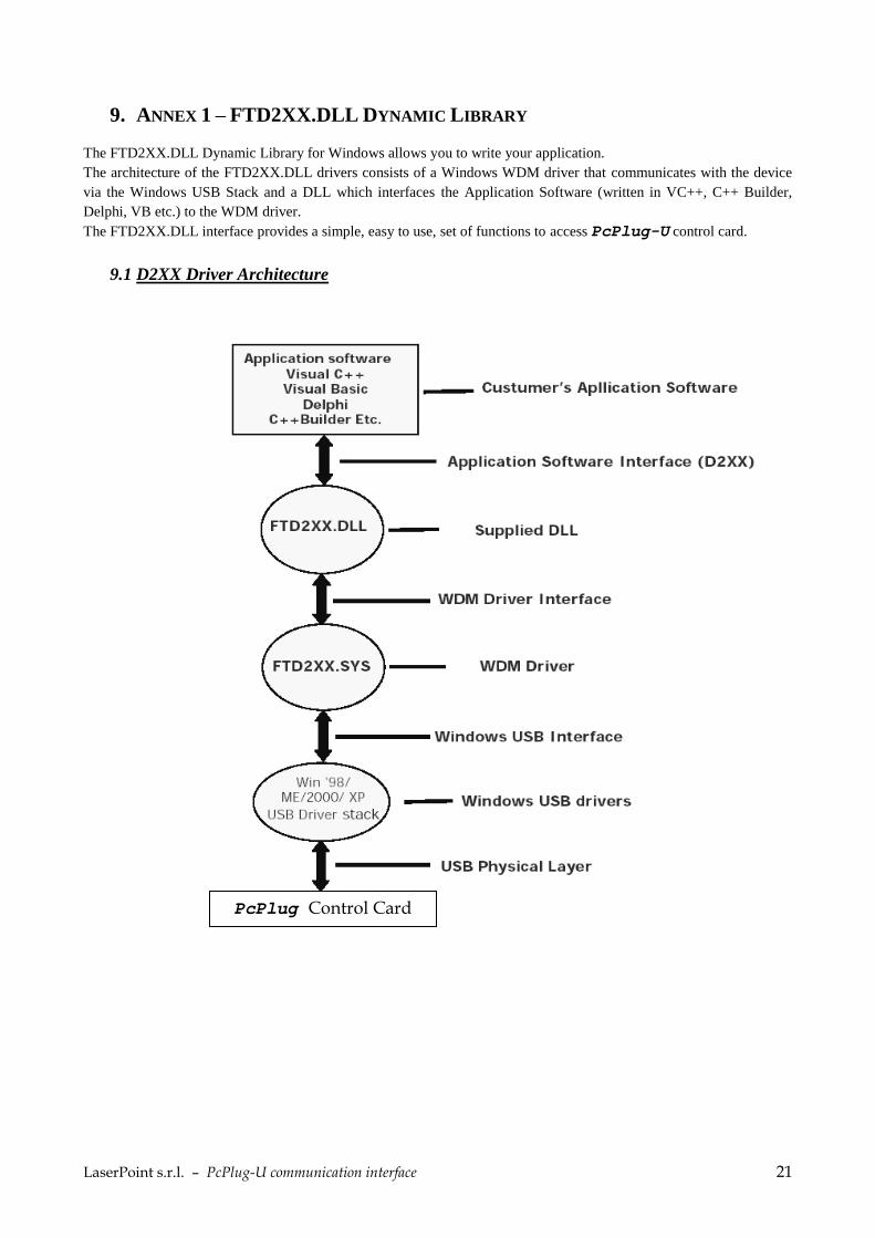
9. ANNEX 1 – FTD2XX.DLL DYNAMIC LIBRARY
The FTD2XX.DLL Dynamic Library for Windows allows you to write your application.
The architecture of the FTD2XX.DLL drivers consists of a Windows WDM driver that communicates with the device
via the Windows USB Stack and a DLL which interfaces the Application Software (written in VC++, C++ Builder,
Delphi, VB etc.) to the WDM driver.
The FTD2XX.DLL interface provides a simple, easy to use, set of functions to access PcPlug-U control card.
9.1 D2XX Driver Architecture
PcPlug Control Card

LaserPoint s.r.l. – PcPlug-U communication interface 22
9.2 Useful links for FTDI drivers and libraries:
For a complete list and description of FTDXXX functions, please download the “FTD2XX Programmer's Guide” at this
link:
http://www.ftdichip.com/Support/Documents/ProgramGuides.htm To download the right libraries for your Operative System / architecture please check this section of FTDI website:
http://www.ftdichip.com/Drivers/D2XX.htm For software examples with different programming languages please check this section:
http://www.ftdichip.com/Support/SoftwareExamples/CodeExamples.htm
9.3 DLL Functions
Here below we report only an extract of the “FTD2XX Programmer’s Guide” (for the full document see the link above),
that collects the most important functions that may be used to identify and communicate with the PcPlug-U:
FT_ListDevices
Description Gets information concerning the devices currently connected. This function can return such information as the number of devices connected, and device strings such as serial number and product description. Syntax FT_STATUS FT_ListDevices (PVOID pvArg1, PVOID pvArg2, DWORD dwFlags) Parameters pvArg1 meaning depend on the dwFlags value (see note below) pvArg2 meaning depend on the dwFlags value (see note below) dwFlags Determines format of returned information (see note below) Return Value FT_OK if successful, otherwise the return value is an FT error code Note Remarks This function can be used in a number of ways to return different types of information. In its simplest form, it can be used to return the number of devices currently connected. If FT_LIST_NUMBER_ONLY bit is set in dwFlags, the parameter pvArg1 is interpreted as a pointer to a DWORD location to store the number of devices currently connected. It can be used to return device string information. If FT_OPEN_BY_SERIAL_NUMBER bit is set in dwFlags, the serial number string will be returned from this function. If FT_OPEN_BY_DESCRIPTION bit is set in dwFlags, the product description string will be returned from this function. If neither of these bits is set, the serial number string will be returned by default. It can be used to return device string information for a single device. If FT_LIST_BY_INDEX bit is set in dwFlags, the parameter pvArg1 is interpreted as the index of the device, and the parameter pvArg2 is interpreted as a pointer to a buffer to contain the appropriate string. Indexes are zerobased, and the error code FT_DEVICE_NOT_FOUND is returned for an invalid index. It can be used to return device string information for all connected devices. If FT_LIST_ALL bit is set in dwFlags, the parameter pvArg1 is interpreted as a pointer to an array of pointers to buffers to contain the appropriate strings, and the parameter pvArg2 is interpreted as a pointer to a DWORD location to store the number of devices currently connected. Note that, for pvArg1, the last entry in the array of pointers to buffers should be a NULL pointer so the array will contain one more location than the number of devices connected.
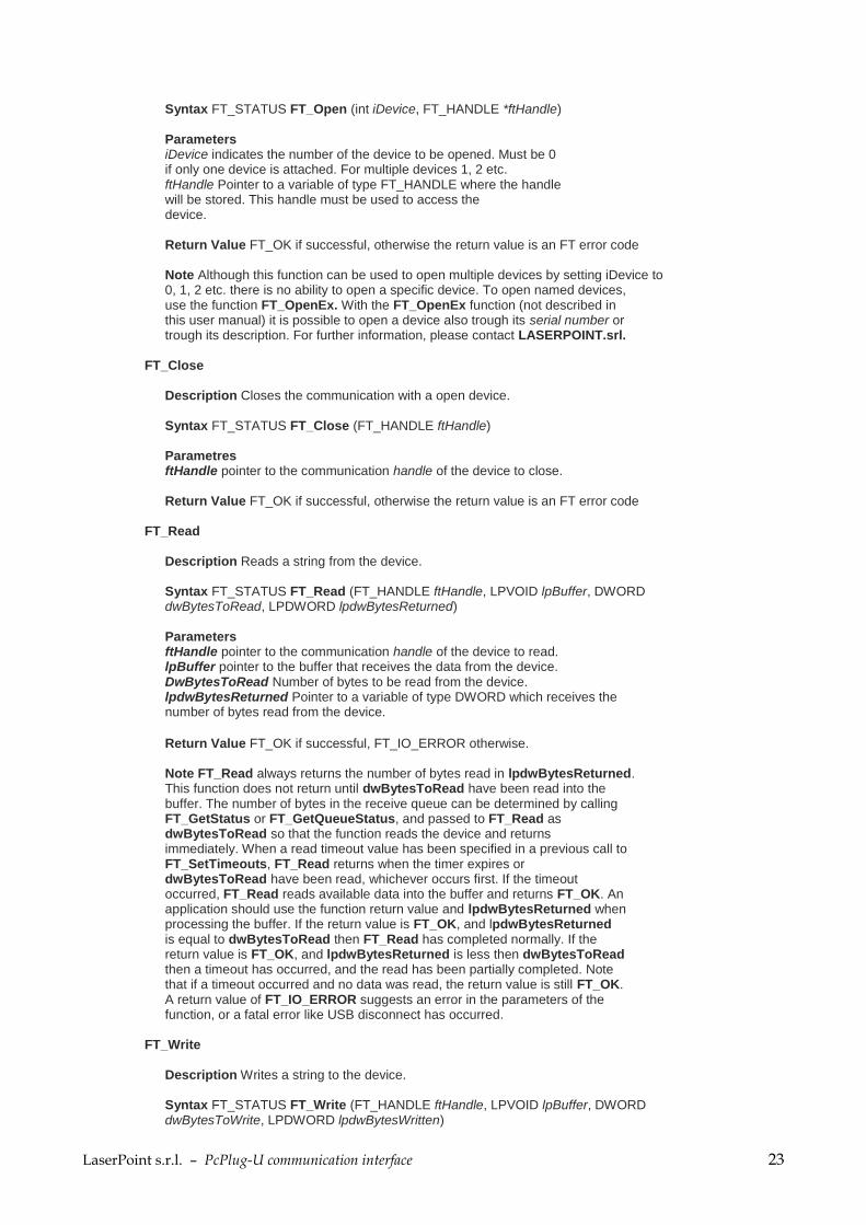
FT_Open
Description Opens the device and return a handle which will be used for subsequent accesses.
LaserPoint s.r.l. – PcPlug-U communication interface 23
Syntax FT_STATUS FT_Open (int iDevice, FT_HANDLE *ftHandle) Parameters iDevice indicates the number of the device to be opened. Must be 0 if only one device is attached. For multiple devices 1, 2 etc. ftHandle Pointer to a variable of type FT_HANDLE where the handle will be stored. This handle must be used to access the device. Return Value FT_OK if successful, otherwise the return value is an FT error code Note Although this function can be used to open multiple devices by setting iDevice to 0, 1, 2 etc. there is no ability to open a specific device. To open named devices, use the function FT_OpenEx. With the FT_OpenEx function (not described in this user manual) it is possible to open a device also trough its serial number or trough its description. For further information, please contact LASERPOINT.srl.
FT_Close Description Closes the communication with a open device. Syntax FT_STATUS FT_Close (FT_HANDLE ftHandle) Parametres ftHandle pointer to the communication handle of the device to close. Return Value FT_OK if successful, otherwise the return value is an FT error code
FT_Read Description Reads a string from the device. Syntax FT_STATUS FT_Read (FT_HANDLE ftHandle, LPVOID lpBuffer, DWORD dwBytesToRead, LPDWORD lpdwBytesReturned) Parameters ftHandle pointer to the communication handle of the device to read. lpBuffer pointer to the buffer that receives the data from the device. DwBytesToRead Number of bytes to be read from the device. lpdwBytesReturned Pointer to a variable of type DWORD which receives the number of bytes read from the device.
Return Value FT_OK if successful, FT_IO_ERROR otherwise. Note FT_Read always returns the number of bytes read in lpdwBytesReturned. This function does not return until dwBytesToRead have been read into the buffer. The number of bytes in the receive queue can be determined by calling FT_GetStatus or FT_GetQueueStatus, and passed to FT_Read as dwBytesToRead so that the function reads the device and returns immediately. When a read timeout value has been specified in a previous call to FT_SetTimeouts, FT_Read returns when the timer expires or dwBytesToRead have been read, whichever occurs first. If the timeout occurred, FT_Read reads available data into the buffer and returns FT_OK. An application should use the function return value and lpdwBytesReturned when processing the buffer. If the return value is FT_OK, and lpdwBytesReturned is equal to dwBytesToRead then FT_Read has completed normally. If the return value is FT_OK, and lpdwBytesReturned is less then dwBytesToRead then a timeout has occurred, and the read has been partially completed. Note that if a timeout occurred and no data was read, the return value is still FT_OK. A return value of FT_IO_ERROR suggests an error in the parameters of the function, or a fatal error like USB disconnect has occurred.
FT_Write Description Writes a string to the device. Syntax FT_STATUS FT_Write (FT_HANDLE ftHandle, LPVOID lpBuffer, DWORD dwBytesToWrite, LPDWORD lpdwBytesWritten)
LaserPoint s.r.l. – PcPlug-U communication interface 24
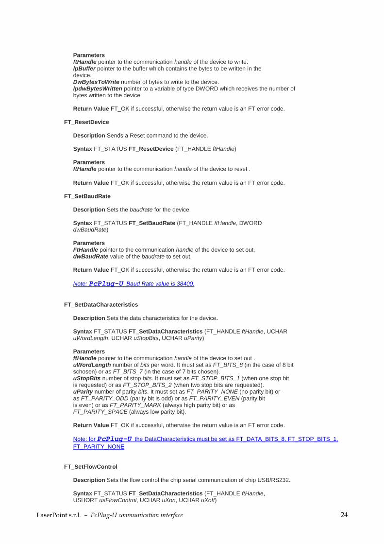
Parameters ftHandle pointer to the communication handle of the device to write. lpBuffer pointer to the buffer which contains the bytes to be written in the device. DwBytesToWrite number of bytes to write to the device. lpdwBytesWritten pointer to a variable of type DWORD which receives the number of bytes written to the device Return Value FT_OK if successful, otherwise the return value is an FT error code.
FT_ResetDevice Description Sends a Reset command to the device. Syntax FT_STATUS FT_ResetDevice (FT_HANDLE ftHandle) Parameters ftHandle pointer to the communication handle of the device to reset .
Return Value FT_OK if successful, otherwise the return value is an FT error code.
FT_SetBaudRate Description Sets the baudrate for the device. Syntax FT_STATUS FT_SetBaudRate (FT_HANDLE ftHandle, DWORD dwBaudRate) Parameters FtHandle pointer to the communication handle of the device to set out. dwBaudRate value of the baudrate to set out. Return Value FT_OK if successful, otherwise the return value is an FT error code.
Note: PcPlug-U Baud Rate value is 38400.
FT_SetDataCharacteristics
Description Sets the data characteristics for the device. Syntax FT_STATUS FT_SetDataCharacteristics (FT_HANDLE ftHandle, UCHAR uWordLength, UCHAR uStopBits, UCHAR uParity) Parameters ftHandle pointer to the communication handle of the device to set out . uWordLength number of bits per word. It must set as FT_BITS_8 (in the case of 8 bit schosen) or as FT_BITS_7 (in the case of 7 bits chosen). uStopBits number of stop bits. It must set as FT_STOP_BITS_1 (when one stop bit is requested) or as FT_STOP_BITS_2 (when two stop bits are requested). uParity number of parity bits. It must set as FT_PARITY_NONE (no parity bit) or as FT_PARITY_ODD (parity bit is odd) or as FT_PARITY_EVEN (parity bit is even) or as FT_PARITY_MARK (always high parity bit) or as FT_PARITY_SPACE (always low parity bit). Return Value FT_OK if successful, otherwise the return value is an FT error code.
Note: for PcPlug-U the DataCharacteristics must be set as FT_DATA_BITS_8, FT_STOP_BITS_1,
FT_PARITY_NONE
FT_SetFlowControl Description Sets the flow control the chip serial communication of chip USB/RS232. Syntax FT_STATUS FT_SetDataCharacteristics (FT_HANDLE ftHandle, USHORT usFlowControl, UCHAR uXon, UCHAR uXoff)

LaserPoint s.r.l. – PcPlug-U communication interface 25
Parameters FtHandle pointer to the communication handle of the device to set out. usFlowControl set the kind of flow control. It must be set as FT_FLOW_NONE (no flow control) or as FT_FLOW_RTS_CTS (hardware RTS/CTS flow control) or as FT_FLOW_DTR_DSR (hardware DTR/DSR flow control) or as FT_FLOW_XON_XOFF (software XON/XOFF flow control) uXon shows the character uses as Xon signal. It must be set only when the flow control is software XON/XOFF kind (otherwise, it must be set as zero). uXoff shows the character uses as Xoff signal. It must be set only when the flow control is software XON/XOFF kind (otherwise, it must be set as zero). Return Value FT_OK if successful, otherwise the return value is an FT error code.
Note: for PcPlug-U the FlowControl must be set as FT_FLOW_NONE
FT_SetDTR Description Sets the Data Terminal Ready (DTR) control signal. (Data Terminal Ready). Syntax FT_STATUS FT_SetDTR (FT_HANDLE ftHandle) Parameters ftHandle pointer to the communication handle of the DTR device to set out. Return Value FT_OK if successful, otherwise the return value is an FT error code.
FT_ClrDTR Description This function clears the Data Terminal Ready (DTR) control signal (Data Terminal Ready). Syntax FT_STATUS FT_ClrDTR (FT_HANDLE ftHandle) Parameters ftHandle pointer to the communication handle of the DTR device to set out. Return Value FT_OK if successful, otherwise the return value is an FT error code.
FT_SetRTS Description Sets the Request To Send (RTS) control signal. (Request To Send). Syntax FT_STATUS FT_SetDTR (FT_HANDLE ftHandle) Parameters ftHandle pointer to the communication handle of the RTS device to set out. Return Value FT_OK if successful, otherwise the return value is an FT error code.
FT_ClrRTS Description Clears the Request To Send (RTS) control signal (Request To Send). Syntax FT_STATUS FT_SetDTR (FT_HANDLE ftHandle) Parameters FtHandle pointer to the communication handle of the RTS device to set out. Return Value FT_OK if successful, otherwise the return value is an FT error code.
FT_SetTimeouts Description Sets the read and write timeouts for the device.

LaserPoint s.r.l. – PcPlug-U communication interface 26
Syntax FT_STATUS FT_SetBaudRate (FT_HANDLE ftHandle, DWORD dwReadTimeout, DWORD dwWriteTimeout) Parameters FtHandle pointer to the communication handle of the device to set out . dwReadTimeout value of the Read timeout, in milliseconds, to set out. dwWriteTimeout value of the Write timeout, in milliseconds, to set out. Return Value FT_OK if successful, otherwise the return value is an FT error code.
FT_GetQueueStatus Description Shows the number of characters in the receive queue. Syntax FT_STATUS FT_GetQueueStatus (FT_HANDLE ftHandle, LPDWORD lpdwAmountInRxQueue) Parameters FtHandle pointer to the communication handle of the device to set out . lpdwAmountInRxQueue Pointer to a variable of type DWORD which receives the number of characters in the receive queue. Return Value FT_OK if successful, otherwise the return value is an FT error code.
FT_GetStatus Description Shows the device status including number of characters in the receive queue, number of characters in the transmit queue, and the current event status. Syntax FT_STATUS FT_GetStatus (FT_HANDLE ftHandle, LPDWORD lpdwAmountInRxQueue , LPDWORD lpdwAmountInTxQueue, LPDWORD lpdwEventstatus) Parameters ftHandle pointer to the communication handle of the device to set out . lpdwAmountInRxQueu Pointer to a variable of type DWORD which receives the number of characters in the receive queue. LpdwAmountInTxQueue Pointer to a variable of type DWORD which receives the number of characters in the transmit queue. lpdwEventstatus Pointer to a variable of type DWORD which receives the current state of the event status. Return Value FT_OK if successful, otherwise the return value is an FT error code.
FTD2XX - Error codes FT_OK = 0 FT_INVALID_HANDLE = 1 FT_DEVICE_NOT_FOUND = 2 FT_DEVICE_NOT_OPENED = 3 FT_IO_ERROR = 4 FT_INSUFFICIENT_RESOURCES = 5 FT_INVALID_PARAMETER = 6 FT_INVALID_BAUD_RATE = 7 FT_DEVICE_NOT_OPENED_FOR_ERASE = 8 FT_DEVICE_NOT_OPENED_FOR_WRITE = 9 FT_FAILED_TO_WRITE_DEVICE = 10 FT_EEPROM_READ_FAILED = 11 FT_EEPROM_WRITE_FAILED = 12 FT_EEPROM_ERASE_FAILED = 13 FT_EEPROM_NOT_PRESENT = 14 FT_EEPROM_NOT_PROGRAMMED = 15 FT_INVALID_ARGS = 16