pdf (3.13 mb) - iopscience
TRANSCRIPT

PAPER • OPEN ACCESS
Theory of resonance shifts of whispering gallerymodes by arbitrary plasmonic nanoparticlesTo cite this article: Matthew R Foreman and Frank Vollmer 2013 New J. Phys. 15 083006
View the article online for updates and enhancements.
You may also likeWhispering-gallery mode compositesensors for on-chip dynamic temperaturemonitoringMatthew Frenkel, Marlon Avellan andZhixiong Guo
-
Nonlinear and quantum optics withwhispering gallery resonatorsDmitry V Strekalov, Christoph Marquardt,Andrey B Matsko et al.
-
Brillouin lasing in whispering gallery micro-resonatorsB Sturman and I Breunig
-
Recent citationsQuantum nanophotonic andnanoplasmonic sensing: towards quantumoptical bioscience laboratories on chipJolly Xavier et al
-
Maximal interaction of electromagneticradiation with corona virionsConstantinos Valagiannopoulos and AriSihvola
-
Plasmonic and hybrid Whispering GalleryMode Based Biosensors: A LiteratureReview (Preprint)Maurizio Manzo et al
-
This content was downloaded from IP address 179.106.81.152 on 14/12/2021 at 21:34

Theory of resonance shifts of whispering gallerymodes by arbitrary plasmonic nanoparticles
Matthew R Foreman1 and Frank VollmerMax Planck Institute for the Science of Light, Laboratory of Nanophotonics andBiosensing, Gunther-Scharowsky-Straße 1, D-91058 Erlangen, GermanyE-mail: [email protected]
New Journal of Physics 15 (2013) 083006 (27pp)Received 3 April 2013Published 2 August 2013Online at http://www.njp.org/doi:10.1088/1367-2630/15/8/083006
Abstract. Shifts of the resonance frequency of high Q whisperinggallery modes (WGMs) in spherical dielectric microresonators by plasmonicnanoparticles can be greater than the WGM line width, such that the perturbationtheory commonly used for describing resonance shifts by dielectric nanoparticles(Teraoka and Arnold 2006 J. Opt. Soc. Am. B 23 1381) is no longerapplicable. This paper therefore reports on an analytic framework, basedon generalized Lorenz–Mie theory, capable of describing resonance shiftsby metallic nanoparticles supporting plasmon oscillations. Generalization tonanoparticles of arbitrary geometry is presented by employing the extendedboundary condition method. Within this framework, hybrid resonance conditionsfor coupled spherical photonic and plasmonic resonators are established andshown to simplify for small plasmonic nanoparticles. Approximate analyticformulae are derived for the shift and broadening of the isolated WGM andplasmon resonances, from which either apparent resonance shifts or modesplitting are shown to follow. Tuning of plasmon resonances using, for example,core–shell nanoparticles to attain a large spectral overlap between WGM andplasmon resonances is demonstrated to significantly enhance the magnitude ofresonance shifts, with a 60-fold enhancement achieved without any optimization.Hybridization of photonic–plasmonic resonances is furthermore demonstrated
1 Author to whom any correspondence should be addressed.
Content from this work may be used under the terms of the Creative Commons Attribution 3.0 licence.Any further distribution of this work must maintain attribution to the author(s) and the title of the work, journal
citation and DOI.
New Journal of Physics 15 (2013) 0830061367-2630/13/083006+27$33.00 © IOP Publishing Ltd and Deutsche Physikalische Gesellschaft

2
(in addition to hybridization of transverse electric–transverse magnetic WGMs)and the associated level repulsion illustrated. Finally, the dependence of WGMresonance shifts on the orientation of silver nanorods is theoretically investigatedand found to be strong by virtue of the asymmetry of the nanorod.
Contents
1. Introduction 22. Formulation of the problem 43. Resonance conditions 84. Approximate extinction spectra 105. Results 13
5.1. Dielectric and solid metallic spherical nanoparticles—model validation andmode splitting . . . . . . . . . . . . . . . . . . . . . . . . . . . . . . . . . . . 13
5.2. Core–shell nanoparticles—mode hybridization and level repulsion . . . . . . . 175.3. Metallic nanorods—orientational dependence . . . . . . . . . . . . . . . . . . 20
6. Discussion 21Appendix A. Definition of the Mie modes 23Appendix B. Mie expansions in shifted coordinate systems 23Appendix C. Scaling parameter for a core–shell nanoparticle 24Appendix D. Derivation of equation (23) 25References 25
1. Introduction
The field of nanoplasmonics is undoubtedly one that has attracted much research effort in recentyears, and has seen successful results in a wide array of applications, such as single moleculespectroscopy, improved drug delivery, light harvesting, integrated circuits and much more [1, 2].Whilst the motivation for exploitation of plasmonic structures varies between applications, theirpopularity typically derives from the ability to strongly localize an optical field and the abilityto modify, control and optimize the resonant nature of coupling between light and electrons [3].Within this rapidly developing and multidisciplinary science, one research direction that hasemerged, for example, is the use of plasmon resonances for both chemical and biological sensingpurposes [4]. Phenomenologically, plasmonic sensors rely on the sensitivity of the resonancefrequency of either surface [5, 6] or localized plasmons [7] excited in metallic structures, tothe properties of the local environment, such as refractive index. For example, when a (large)molecule is in close proximity to a surface plasmon sensor, the effective optical path lengthtravelled by a resonant surface mode is increased, resulting in a shift in the resonance frequency,which can be detected by monitoring the transmission properties of a swept laser or broadbandsource [8].
Ohmic losses in metals, however, imply that plasmons are short lived and consequentlyplasmon resonances are broad. Low Q factors (∼100) inherent in plasmonic sensing hencelimit sensitivity levels achievable, making them unsuitable for applications demanding single, orfew, molecule sensitivity, such as early pathogen/toxin detection. Dielectric whispering gallerymode resonators (WGMRs), however, represent a similar sensing technology, whereby it is
New Journal of Physics 15 (2013) 083006 (http://www.njp.org/)

3
the sensitivity of optical resonances in dielectric cavities, e.g. a microsphere, that is exploitedto probe the local surroundings [9]. Since dielectric materials exhibit far lower absorptionthan metals, high Q resonances can be supported (ultimately limited to ∼1010 [10]), and thussensitivity levels are intrinsically higher, allowing detection down to the single virus level [11].
Traditionally, shifts in resonance frequencies are analysed using, what has become knownas, the reactive sensing principle [12], which derives from a first order perturbation treatmentof electromagnetic scattering, originally derived in the microwave domain [13, 14], but laterextended into the optical regime by Arnold and co-workers [15–17]. Specifically, the reactivesensing principle states that the spectral position of a whispering gallery mode (WGM)resonance is shifted when a nanoparticle (NP) enters the evanescent field of a WGMR by anamount inversely proportional to the energy in the WGMR and proportional to the local intensityseen by the NP and the polarizability of the NP (cf equation (25) below). Combination of highQ dielectric WGMRs and plasmonic NPs, therefore represents a means by which the detectionenvelope can be pushed further. Two alternative approaches are, indeed, currently beingactively pursued in this vein, namely exploitation of local field enhancements, or plasmonichotspots [18–22] and use of NPs as analyte labels [23–25], whereby sensitivity gains follow byvirtue of the increased near field or NP polarizability respectively.
Despite the widespread success of the reactive sensing principle, its validity is known tobe restricted to scenarios in which resonance shifts are less than half the line width of theWGM [26]. Use of plasmonic NPs to increase the magnitude of resonance shifts can thereforenecessitate the use of an alternative theory since resonance shifts can be greatly amplified. Toillustrate this point consider a typical WGM resonance with a Q factor 106 or 105, i.e. a spectralwidth on the order of 1–10 pm. Theoretically, it has been shown [20] that adsorption of anindividual MS2 virus gives rise to a resonance shift of approximately 0.25 fm (or equivalently0.25 × 10−3–0.25 × 10⁻⁴ line widths respectively), yet near field intensity enhancements ashigh as 105 have been reported in the literature [27]. Shifts greater than resonance line widthsare hence entirely plausible, if not expected, in NP based optical WGM sensing. Ultra-highQ resonances have, similarly, been shown to undergo mode splitting upon interaction withsmall dielectric scatterers [28, 29], which cannot be described using the reactive sensingprinciple. Conditions for observing mode splitting with metal-based NPs are, moreover, lessstringent than for dielectric NPs because they (a) have a larger off-resonance polarizability inthe optical regime, and (b) can support collective electron excitations, i.e. plasmons, leadingto enhanced coupling. It should also be noted that with increasing coupling strength comesincreased scattering losses, in turn implying broadening of WGM resonances. Again the needfor an alternative description is evident, since these feature are not accounted for by thereactive sensing principle.
With these points in mind, this paper aims to present an analytic framework, withinwhich the perturbation of WGMRs by arbitrary plasmonic NPs can be described. Section 2presents the fundamental scattering formalism used to do so. The work described therein extendsearlier literature which considered perturbations to WGMRs from spherical dielectric Rayleighscatterers by employing generalized Lorenz–Mie theory [29]. Here, however, scattering fromlarger particle sizes is considered, with simplifications for smaller NPs given later. MetallicNPs can also be fully described within the scattering framework given here, such that resultingformulae embody plasmonic effects. Application of Waterman’s extended boundary conditionmethod [30], furthermore, allows arbitrary NP geometries, such as core–shells, nanorods andnanocubes, to be described. Section 3 proceeds to derive hybrid photonic–plasmonic resonance
New Journal of Physics 15 (2013) 083006 (http://www.njp.org/)

4
Figure 1. Geometry and coordinate systems used in the coupling calculations.
conditions for the WGMR-NP system. Naturally, the formulae obtained are more involved thanthose derived from the reactive sensing principle, however this reflects the richer physics whichthey express. Nevertheless, simplifications are sought to aid ease of use, with approximatesolutions presented in concert to exact results. Section 4 briefly describes an approximate meansby which the extinction spectrum of the hybrid resonant system can be determined, without theneed to solve the full scattering problem, before numerical results are given in section 5. Inview of the wealth of physical effects that stem from the coupled resonator system, such as modehybridization and resonance splitting, section 5 attempts to give a brief survey of NP geometriesfrom which they can arise. Accordingly, after initial model verification using homogeneousdielectric spherical NPs, results are presented for metallic spheres, resonant core–shell NPs andnanorods. Discussion of the results is given in section 6. With the aim of facilitating practicalimplementation of the theory, a number of supplementary appendices are also given elaboratinga number of finer mathematical details.
2. Formulation of the problem
In this paper the resonance shift of WGMs within a spherical WGMR due to the presence of anarbitrary NP will be considered. Attention will initially be restricted to spherical NPs, howeverextension to composite NPs, such as core–shell NPs, and more complex geometries, such asnanorods, will subsequently be given. Figure 1 depicts the system geometry under consideration,whereby three distinct regions, labelled I, II and III, can be seen. Initially, restricting to sphericalNPs, regions II and III define the volume of the WGMR and NP respectively, whilst I denotesthe medium within which they are immersed. Employing generalized Lorenz–Mie theory [31],the electric field within each of these regions can thus be represented as a superposition ofmultipole (or Mie) modes, Eν( j)
lm (r), viz:
EI(r)=
∑ν,lm
aνlmEν(3)lm (r)+ bνlmEν(1)
lm (r)+ dνlmEν(1)lm (r − rNP), (1a)
New Journal of Physics 15 (2013) 083006 (http://www.njp.org/)

5
EII(r)=
∑ν,lm
cνlmEν(3)lm (r), (1b)
EIII(r)=
∑ν,lm
f νlmEν(3)lm (r − rNP). (1c)
Explicit expressions for the Mie modes are given in appendix A, however here it isnoted that each Mie mode is indexed by the polar and azimuthal numbers l = 1, 2, . . . , andm = −l,−l + 1, . . . , l. ν denotes either electric (E) or magnetic (m) Mie modes (also commonlyreferred to as transverse magnetic (TM) and transverse electric (TE) respectively). Physically,the j = 1 modes represent multipole sources, in which energy flows outward from r = 0 whilstj = 2 represents field sinks with energy flowing inwards towards the sink position. In contrast,j = 3 modes constitute a superposition of both j = 1 and 2 in equal measure such that they havefinite energy density at the origin. Accordingly, the expansion coefficients aνlm , bνlm , cνlm , dνlm andf νlm represent the illumination field, the field scattered from the WGMR, the field within theWGMR, the field scattered from the NP and the field within the NP respectively.
Imposing continuity of the tangential field components at the surface of the WGMR andNP allows the expansion coefficients to be analytically related, however it should be noted fromequations (1) that the expansions of the field scattered from, and generated within, the NP areperformed in a coordinate system with origin at r = rNP, i.e. the centre of the NP (as denotedby the tilde notation). Matching of the fields, therefore, is most easily accomplished if the shiftformulae, equations (B.2), are used to express all modes in the same coordinate system, whichleads to the continuity equations:[
aνlm + dνlm]ψ(3)l (kIrII)+ bνlmψ
(1)l (kIrII)= cνlmψ
(3)l (kIIrII), (2a)[
aνlm + bνlm]ψ(3)l (kIrIII)+ dνlmψ
(1)l (kIrIII)= f νlmψ
(3)l (kIIIrIII), (2b)
kIs
[aνlm + dνlm
]h(3)l (k
IrII)+ bνlmh(1)l (kIrII)= kII
s cνlmh(3)l (kIIrII), (2c)
kIs
[aνlm+ bνlm
]h(3)l (k
IrIII)+ dνlmh(1)l (kIrIII)= kIII
s f νlmh(3)l (kIIIrIII), (2d)
where ψ ( j)l (z)= ∂[zh( j)
l (z)]/∂z and s = 1, 2 for ν = E,M respectively.WGMRs are commonly excited by means of a tapered fibre or prism [32], such that the
illumination field is only significant over a small region of space near one side of the WGMR. Assuch it is reasonable to neglect the aνlm terms in both equations (2b) and (2d), which describe theillumination field near the NP. Following standard algebraic manipulation, equations (2a)–(2d)yield the scaling relations:
bνlm = ηνl (kI, kII, rII)
[aνlm + dνlm
], (3a)
cνlm = ζ νl (kI, kII, rII)
[aνlm + dνlm
], (3b)
dνlm = ηνl (kI, kIII, rIII) bνlm, (3c)
f νlm = ζ νl (kI, kIII, rIII) bνlm, (3d)
New Journal of Physics 15 (2013) 083006 (http://www.njp.org/)
6
where
ηνl (ki , k j , ρ)=
kish(3)l (k
iρ)ψ(3)l (k jρ)− k j
s h(3)l (kjρ)ψ
(3)l (kiρ)
k js h(3)l (k
jρ)ψ(1)l (kiρ)− ki
sh(1)l (k
iρ)ψ(3)l (k jρ)
, (4a)
ζ νl (ki , k j , ρ)=
kish(3)l (k
iρ)ψ(1)l (kiρ)− ki
sh(1)l (k
iρ)ψ(3)l (kiρ)
k js h(3)l (k
jρ)ψ(1)l (kiρ)− ki
sh(1)l (k
iρ)ψ(3)l (k jρ)
. (4b)
Henceforth, the notation ην,1l = ηνl (kI, kII, rII) and ην,2l = ηνl (k
I, kIII, rIII) (and similarly for ζ ν,il )will be used, for simplicity. For later convenience the scaling coefficient γ ν,il = η
ν,il /ζ
ν,il is also
defined here.To reduce the system of equations defined by equations (3), the shift formulae
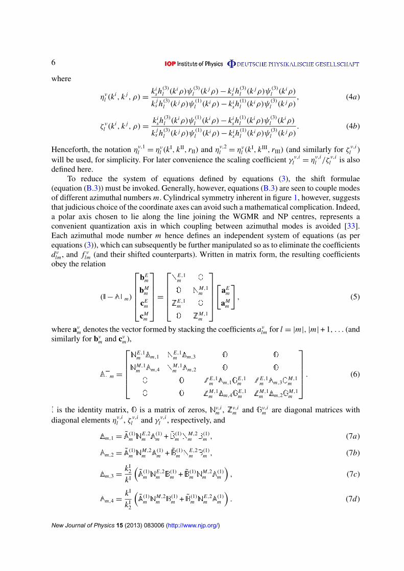
(equation (B.3)) must be invoked. Generally, however, equations (B.3) are seen to couple modesof different azimuthal numbers m. Cylindrical symmetry inherent in figure 1, however, suggeststhat judicious choice of the coordinate axes can avoid such a mathematical complication. Indeed,a polar axis chosen to lie along the line joining the WGMR and NP centres, represents aconvenient quantization axis in which coupling between azimuthal modes is avoided [33].Each azimuthal mode number m hence defines an independent system of equations (as perequations (3)), which can subsequently be further manipulated so as to eliminate the coefficientsdνlm , and f νlm (and their shifted counterparts). Written in matrix form, the resulting coefficientsobey the relation
(I−��m)
bE
m
bMm
cEm
cMm
=
N
E,1m O
O NM,1m
ZE,1m O
O ZM,1m
[
aEm
aMm
], (5)
where aνm denotes the vector formed by stacking the coefficients aνlm for l = |m|, |m| + 1, . . . (andsimilarly for bνm and cνm),
��m =
N
E,1m �m,1 N
E,1m �m,3 O O
NM,1m �m,4 N
M,1m �m,2 O O
O O ZE,1m �m,1G
E,1m Z
E,1m �m,3G
M,1m
O O ZM,1m �m,4G
E,1m Z
M,1m �m,2G
M,1m
. (6)
I is the identity matrix, O is a matrix of zeros, Nν,im , Zν,im and Gν,im are diagonal matrices with
diagonal elements ην,il , ζ ν,il and γ ν,il , respectively, and
�m,1 = A(1)m N
E,2m A
(1)m + B(1)m N
M,2m B
(1)m , (7a)
�m,2 = A(1)m N
M,2m A
(1)m + B(1)m N
E,2m B
(1)m , (7b)
�m,3 =kI
2
kI
(A(1)m N
E,2m B
(1)m + B(1)m N
M,2m A
(1)m
), (7c)
�m,4 =kI
kI2
(A(1)m N
M,2m B
(1)m + B(1)m N
E,2m A
(1)m
). (7d)
New Journal of Physics 15 (2013) 083006 (http://www.njp.org/)

7
Table 1. Parameter values for equation (9).
j ν (ν) µ (µ) S ABj SB A
j SB Bj
1 E (M) M (E) kI/kI2 kI
2/kI 1
2 M (E) E (M) kI2/kI kI/kI
2 1
3 E (M) M (E) kI2/kI kI
2/kI (kI2/kI)2
4 M (E) E (M) kI/kI2 kI/kI
2 (kI/kI2)
2
The matrices A(1)m and B
(1)m are full matrices with elements given by (with a slight abuse
of notation) AlmLm = Alm(1)
Lm (rNP) and BlmLm = Blm(1)
Lm (rNP) (see appendix B). Similarly A(1)m and
B(1)m describe shifts in the opposite direction and are thus formed from the elements Alm
Lm =
Alm(1)Lm (−rNP) and B
lmLm = Blm(1)
Lm (−rNP).Extension of the presented scattering formalism to consider non-spherical NPs can be
achieved with recourse to the extended boundary condition method originally proposed byWaterman [30, 34]. In this paradigm, region III no longer defines the volume of a spherical NP,but instead is defined by a fictitious spherical surface circumscribing an arbitrarily shaped, finiteNP (see figure 1). The incident field and the field ‘scattered’ from this fictitious surface is onceagain represented as a superposition of Mie modes. Expansion coefficients of the incident andscattered fields are then related by the so-called T-matrix of the NP, such that in the derivationsabove equation (3c) becomes[
dE
dM
]=
TE ET
E M
TM E
TM M
[bE
bM
]. (8)
An analogous equation, for the f νlm coefficients (albeit now only valid within the NP volumeand not the entirety of region III) can also be written in terms of a Q-matrix [35], howeverthis is not required for the present derivations and is hence omitted. The elements of the T-matrix can be found, by performing surface integrals of cross products of different combinationsof Mie modes over the surface of the NP (see [35] for full details), for which efficientand accurate routines already exist. For absorbing materials, such as metals, care must betaken with the algorithmic details by which the T-matrix is calculated [36]. In general, it isimportant to note that equation (8) is not separable in m unless the NP is axial symmetricabout the polar axis (e.g. a circular cylinder). Accordingly, bν denotes the vector formed bystacking the coefficients bνlm for all (l,m) (and similarly for dν). Consequently, the equivalentsystem matrix I−�� is also no longer block diagonal in general and hence the m subscriptmust be dropped. Formally, however, the electromagnetic scattering problem may still beexpressed in the same form as equations (5) and (6) (with omission of the m subscript), exceptnow
� j = A(1)TνµA(1) + S AB
j A(1)TνµB(1) + SB A
j B(1)TνµA(1) + SB B
j B(1)TνµB(1), (9)
where the appropriate values of ν, µ and S j are shown in table 1. The bar notation on ν and µimplies the complimentary mode index (see table 1).
New Journal of Physics 15 (2013) 083006 (http://www.njp.org/)

8
3. Resonance conditions
Resonances in an isolated WGMR follow from equation (5) by setting ��= 0 (i.e. dropping theperturbation of the NP) and looking for complex poles in the matricesNν,1m and Zν,1m . The real andimaginary parts of these roots determine the resonance wavelengths and line width respectively.Since Mie resonances for a single sphere are well known and described in many texts [37, 38]they will not be considered further here, however it is noted that the poles of both N
ν,1m and
Zν,1m occur at the same wavelengths (for a fixed resonator size). Coupling between the NP and
WGMR, however, alters the resonance condition as described by the perturbing matrix ��.Optical resonances for the combined WGMR-NP system, can thus be found by determinationof the roots |I−��| = 0. Given that �� is block diagonal the determinant |I−��| can be writtenas the product of the determinants of the upper diagonal block and lower diagonal block. Thepoles of these blocks, again occur at the same wavelengths (for fixed rII), such that it is sufficientto consider the resonance condition |I−��| = 0, where
��=
[N
E,1�1 N
E,1�3
NM,1�4 N
M,1�2
]. (10)
For axially symmetric NPs, �� is furthermore block diagonal in m, such that determinationof the resonances is computationally easier. Resonance conditions can, however, equivalentlybe expressed via the condition αk
lm = 0, where αklm are the eigenvalues of I−��. It should be
noted that for each mode index (l,m) two eigenvalues can be found, which are indexed bythe superscript k. For an isolated WGMR these two eigenvalues correspond to TM and TEresonances. For the combined WGMR-NP system these resonances can be classified as quasi-TM and -TE modes.
Analytic determination of the eigenvalues of I−�� is, in general, intractable, however anumber of approximations can be made. As a first order approach, matrix perturbation theorycan be applied [39], whereby �� is considered as a perturbation to the identity matrix. Notingthat all eigenvalues of I are unity and that the first order perturbations to these eigenvalues aregiven by the on-diagonal elements of �� yields the resonance conditions for the (l,m) quasi-TM(ν = E) and quasi-TE (ν = M) modes as
0 =1
ην,1l
−
∑L ,L ′
[Alm
LmT ννLmL ′mA
L ′mlm + B
lmLmT νν
LmL ′mBL ′mlm
+ S ABs Alm
LmT ννLmL ′mB
L ′mlm + SB A
s BlmLmT νν
LmL ′mAL ′mlm
], (11)
where again s = 1, 2 for ν = E,M . Asymptotically, equation (11) should reproduce theresonance condition for a bare WGMR as the NP is moved further from the WGMR. LettingrNP → ∞ and observing Alm
Lm and BlmLm → 0 in this limit allows equations (11) to be written in
the form 1/ην,1l = 0, thus confirming physical expectations. When considering spherical NPs,the resonance conditions expressed by equation (11) simplify to
0 =1
ηE,1l
−
∑L
[Alm
LmηE,2L ALm
lm + BlmLmη
M,2L BLm
lm
](12a)
New Journal of Physics 15 (2013) 083006 (http://www.njp.org/)

9
for the quasi-TM mode and
0 =1
ηM,1l
−
∑L
[Alm
LmηM,2L ALm
lm + BlmLmη
E,2L BLm
lm
](12b)
for the quasi-TE mode.Assuming the NP to be small (i.e. k rIII � 1) implies that the NP can further be treated
as a dipole scatterer, such that only L = 1 terms in equation (11) (or equations (12)) needbe considered. If the magnetic dipole terms are also negligible then the first order resonanceconditions can be written
0 =1
ηE,1l η
E,21
− Alm1mA
1mlm for quasi-TM modes, (13a)
0 =1
ηM,1l η
E,21
− Blm1mB
1mlm for quasi-TE modes. (13b)
In this scenario, it is observed that A1mlm = B1m
lm = 0 for |m|> 1, such that only the |m|6 1azimuthal modes experience a shift in resonance frequency from that of an isolated WGMR.Furthermore, it is noted that the m = 0 TE modes also do not experience a shift. For highQ WGM resonances, the shifting of the low order (|m|6 1) azimuthal modes relative to thehigher order modes can give rise to mode splitting [40]. For lower Q resonances, such asthat considered in section 5, a shift of the aggregate spectral line results. This point is furtherdiscussed in section 4.
Since �� is a full matrix equations (11)–(13) only describe approximate resonanceconditions for the hybrid system. For axially symmetric NPs (e.g. nanorods) aligned such thattheir symmetry axis lies along the global polar axis, off diagonal elements of the associated Tmatrix are identically zero and hence the approximation provides accurate results. Naturally, thesame holds true for rotational symmetric NPs such as spheres. If, however, the NP possesses nosymmetry, or the symmetry axis does not lie along the z-axis the approximation worsens. Moreexact resonance conditions than those defined by equations (11)–(13) can, fortunately, be found.To do so requires diagonalization of ��, which can trivially be achieved numerically, whereby itthen follows that αk
lm = 1 −βklm , where βk
lm are the eigenvalues of ��. Analytic diagonalizationof �� can, however, also allow greater physical insight to be obtained, albeit this requires furtherapproximations to be made. For example, if considering spherical NPs, and if coupling betweenmodes of different l is neglected, the matrices �m,i become diagonal, such that each block of��m is also diagonal. Accordingly it follows that
β1,2lm =
1
2
([�m,1
]ll
+[�m,2
]ll±
√([�m,1
]ll−[�m,2
]ll
)2+ 4
[�m,3
]ll
[�m,4
]ll
)(14)
such that
β1lm ≈
[�m,1
]ll
+
[�m,3
]ll
[�m,4
]ll[
�m,1
]ll−[�m,2
]ll
(15a)
and
β2lm ≈
[�m,2
]ll−
[�m,3
]ll
[�m,4
]ll[
�m,1
]ll−[�m,2
]ll
, (15b)
New Journal of Physics 15 (2013) 083006 (http://www.njp.org/)

10
where [X]i j denotes the (i, j)th element of the matrix X. Whilst previously the eigenvaluepairs for each mode index (l,m) could be attributed to TE and TM polarized modes, no suchassociation can be made for equation (14). Instead, inter-polarization coupling, as determinedby the matrices �m,3 and �m,4, gives two hybridized levels with a mixed polarization state.Adopting an electric dipole scattering approximation for the NP, the hybrid resonance conditionsare explicitly given by
0 =1
ηE,1l η
E,21
− Alm1mA
1mlm −
ηM,1l Alm
1mA1mlm B
lm1mB
1mlm
ηE,1l Alm
1mA1mlm − η
M,1l B
lm1mB
1mlm
, (16a)
0 =1
ηM,1l η
E,21
− Blm1mB
1mlm +
ηE,1l Alm
1mA1mlm B
lm1mB
1mlm
ηE,1l Alm
1mA1mlm − η
M,1l B
lm1mB
1mlm
, (16b)
whereby it is evident that in the limiting case of negligible cross-polarization mixing,equations (16) reduce to equations (13). The relative importance of differing approximationsand the associated physical effects remains as the topic of future work. In the remainder of thispaper equations (11)–(13) will be used, unless otherwise stated, so as to elucidate the dominantphysical effects.
The results given here are quite general, however, henceforth only three NP geometries willbe considered, specifically isotropic spherical NPs, core–shell NPs and circular cylindrical NPs(or nanorods). Layered NPs, such as the core–shell geometry, and nanorods are particularlyattractive as plasmonic NPs, due to the tunability of their optical properties [41–43]. Forexample, for a core–shell NP, the plasmon resonance frequency can be varied over a widerange of wavelengths by adjusting the ratio of the inner and outer radius, denoted by rIV andrIII respectively (see inset of figure 5). Similar resonance tuning can be achieved in nanorodsby varying their aspect ratio. Layered NPs are particularly easily treated within the formalismpresented here due to their spherical symmetry, whereby it can be shown that T νν
lm,lm = κν,2l ,
where κν,2l describes the scattering from composite NPs (independent of m) including the effectsof internal reflections between layers. Expressions for κν,2l for a core–shell NP are given inappendix C, however the reader is referred to the work of Mackowski et al [44] for more generalconfigurations. All other elements of the T-matrix are identically zero. For more complicatedstructures, the T-matrix must be determined numerically, as mentioned earlier.
4. Approximate extinction spectra
Complex roots of equations (12) and (13), denoted kνlm , give the resonance wavelength andlinewidth for a single Mie mode of order (l,m). In practice, however, the azimuthal modes for asingle polar index lie in close proximity to each other. Due to their finite widths all such modesmust be considered together. When considering scattering from multiple spheres it can be shownthat the total extinction spectrum is given by the sum of the extinction spectrum for each sphereindividually [45] and in the case under consideration is thus given by
Pext =i
4kI
∑ν,lm
l(l + 1)kIsRe
[aν∗lmbνlm + aν∗lm dνlm
], (17)
where, s = 1, 2 for ν = E,M as usual, ∗ denotes complex conjugation and Pext is the total powerscattered and absorbed by the WGMR-NP system from the illuminating beam. Neglecting the
New Journal of Physics 15 (2013) 083006 (http://www.njp.org/)

11
illumination field at the NP, as before, allows the second term to be safely ignored. Fromequation (17) it is evident that to determine the extinguished power, equation (5) must be solvedto determine the mode coefficients. Unfortunately this is computationally expensive and it ispreferable if such a calculation can be avoided. Accordingly, here an approximate formulationis used, whereby the extinction spectrum in the vicinity of a resonance is represented as asuperposition of Lorentzian resonances, with central frequency and linewidths given by thereal and imaginary parts of the roots of an appropriate resonance condition. The appropriateamplitude of each Lorentzian is then further found from the illumination coefficients aνlm .
For example, when considering small spherical NPs the position and width of eachresonance is first determined from the roots of equations (13). Given further that equations (13)neglect cross-polarization mixing and coupling between modes of differing polar index l,it is legitimate to assume bνlm = σ νlmaνlm . For an isolated WGMR it would immediately (andrigorously) follow that σ νlm = η
ν,1l , however for the coupled WGMR-NP system this relation
is modified for the |m|6 1 modes. Considering equations (5)–(7) under an electric dipolescattering approximation yields
bElm ≈ η
E,1l
[aE
lm −η
E,21 Alm
1m
Um
(∑L
ηE,1L A1m
LmaELm +
kI2
kIη
M,1L B1m
LmaMLm
)](18)
for |m|6 1 and an analogous expression for bMlm , where
Um = ηE,21
∑L
(η
E,1L ALm
1m A1mLm + ηM,1
L BLm1m B
1mLm
)− 1. (19)
Neglecting cross-polarization mixing and coupling between modes of differing polar indextherefore gives
σ Elm ≈ η
E,1l
[1 − η
E,1l η
E,21
Alm1mA
1mlm
Um
], (20a)
σ Mlm ≈ η
M,1l
[1 − η
M,1l η
E,21
Blm1mB
1mlm
Um
]. (20b)
Similar expressions were derived in the work of Deych and Rubin [29, 40] for dielectricspherical Rayleigh scatterers. By virtue of their dependence on the scaling parameters ην, j
l
(or κν,2l when considering core–shell NPs), σ νlm exhibit a wavelength dependence. This can beapproximated by the complex Lorentzian function
σ νlm(k)≈ σ νlm (k0)i00/2
(k − k0)+ i00/2, (21)
where σ νlm (k0) is real, k0 = Re[kνlm]
and 00 = −2 Im[kνlm]. Hence, finally
Pext ≈i
4kI
∑ν,lm
l(l + 1)kIs
020 σ
νlm (k0)
4 (k − k0)2 +02
0
|aνlm|2 (22)
which can easily be measured in a practical experiment, for example, by monitoring the opticalthroughput of the coupling fibre.
If resonance conditions are formed by diagonalizing �� (see section 3), as is appropriatefor more general NP geometries, the simple scaling relation bνlm = σ νlmaνlm no longer holds and
New Journal of Physics 15 (2013) 083006 (http://www.njp.org/)
12
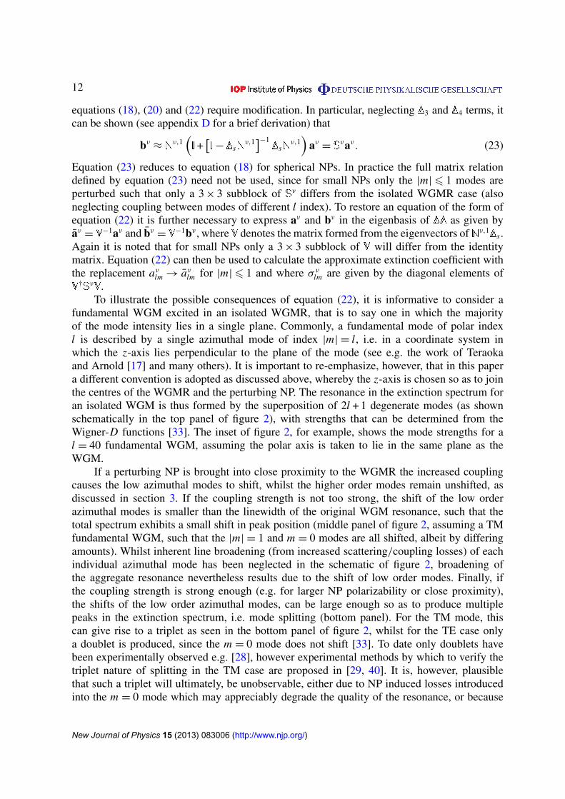
equations (18), (20) and (22) require modification. In particular, neglecting �3 and �4 terms, itcan be shown (see appendix D for a brief derivation) that
bν ≈ Nν,1(I+[I−�sN
ν,1]−1
�sNν,1)
aν = Sνaν. (23)
Equation (23) reduces to equation (18) for spherical NPs. In practice the full matrix relationdefined by equation (23) need not be used, since for small NPs only the |m|6 1 modes areperturbed such that only a 3 × 3 subblock of Sν differs from the isolated WGMR case (alsoneglecting coupling between modes of different l index). To restore an equation of the form ofequation (22) it is further necessary to express aν and bν in the eigenbasis of �� as given byaν = V
−1aν and bν = V−1bν , where V denotes the matrix formed from the eigenvectors ofNν,1�s .
Again it is noted that for small NPs only a 3 × 3 subblock of V will differ from the identitymatrix. Equation (22) can then be used to calculate the approximate extinction coefficient withthe replacement aνlm → aνlm for |m|6 1 and where σ νlm are given by the diagonal elements ofV
†SνV.To illustrate the possible consequences of equation (22), it is informative to consider a
fundamental WGM excited in an isolated WGMR, that is to say one in which the majorityof the mode intensity lies in a single plane. Commonly, a fundamental mode of polar indexl is described by a single azimuthal mode of index |m| = l, i.e. in a coordinate system inwhich the z-axis lies perpendicular to the plane of the mode (see e.g. the work of Teraokaand Arnold [17] and many others). It is important to re-emphasize, however, that in this papera different convention is adopted as discussed above, whereby the z-axis is chosen so as to jointhe centres of the WGMR and the perturbing NP. The resonance in the extinction spectrum foran isolated WGM is thus formed by the superposition of 2l + 1 degenerate modes (as shownschematically in the top panel of figure 2), with strengths that can be determined from theWigner-D functions [33]. The inset of figure 2, for example, shows the mode strengths for al = 40 fundamental WGM, assuming the polar axis is taken to lie in the same plane as theWGM.
If a perturbing NP is brought into close proximity to the WGMR the increased couplingcauses the low azimuthal modes to shift, whilst the higher order modes remain unshifted, asdiscussed in section 3. If the coupling strength is not too strong, the shift of the low orderazimuthal modes is smaller than the linewidth of the original WGM resonance, such that thetotal spectrum exhibits a small shift in peak position (middle panel of figure 2, assuming a TMfundamental WGM, such that the |m| = 1 and m = 0 modes are all shifted, albeit by differingamounts). Whilst inherent line broadening (from increased scattering/coupling losses) of eachindividual azimuthal mode has been neglected in the schematic of figure 2, broadening ofthe aggregate resonance nevertheless results due to the shift of low order modes. Finally, ifthe coupling strength is strong enough (e.g. for larger NP polarizability or close proximity),the shifts of the low order azimuthal modes, can be large enough so as to produce multiplepeaks in the extinction spectrum, i.e. mode splitting (bottom panel). For the TM mode, thiscan give rise to a triplet as seen in the bottom panel of figure 2, whilst for the TE case onlya doublet is produced, since the m = 0 mode does not shift [33]. To date only doublets havebeen experimentally observed e.g. [28], however experimental methods by which to verify thetriplet nature of splitting in the TM case are proposed in [29, 40]. It is, however, plausiblethat such a triplet will ultimately, be unobservable, either due to NP induced losses introducedinto the m = 0 mode which may appreciably degrade the quality of the resonance, or because
New Journal of Physics 15 (2013) 083006 (http://www.njp.org/)

13
Figure 2. Schematic representation of the origin of apparent WGM shifts versusmode splitting, based on the shift of low azimuthal modes only. (inset) Modestrengths of degenerate azimuthal modes in a fundamental l = 40 WGM.
illumination optics also alter the resonant mode structure [46], such that the m = 0 modedegeneracy is lifted. This, however, remains an open experimental question.
5. Results
5.1. Dielectric and solid metallic spherical nanoparticles—model validation and modesplitting
Given the theoretical derivations presented above, a number of studies will be discussed here,through which the coupling between WGMRs and plasmonic NPs is investigated. By way ofinitial validation of the theory, however, a preliminary study of perturbation of a WGMR bya small spherical dielectric particle is considered. This scenario has been well studied in theliterature and resonance shifts are usually determined by applying a first order perturbationapproximation to the vectorial wave equations [16, 17]. Under this approximation the resonanceshift can be shown to be given by
δk0
k0≈ −
(εIII − εI)
2
∫VIII
E∗(r) · E′(r)dr∫V ε(r) |E(r)|
2 dr, (24)
New Journal of Physics 15 (2013) 083006 (http://www.njp.org/)

14
where E(′)(r) is the electric field before (after) introduction of the NP, VIII denotes thevolume of the NP and V denotes all space. Here ε(r) is the permittivity distribution beforeintroduction of the NP, such that ε(r)= εII for r ∈ VII and εI otherwise. Due to the computationalburden in determining the perturbed field E′(r), recourse is customarily made to a quasi-staticapproximation to determine the perturbed field, E′(r) yielding [15]
δk0
k0≈ −
Re[α]
2
|E(rNP)|2∫
V ε(r) |E(r)|2 dr
, (25)
where α is the excess polarizability of the perturbing particle. Note that the domain ofintegration for the integral in the denominator of equation (25) is also commonly taken as VII,i.e. the spatial extent of the WGMR, since this contains the majority of energy of the WGM.This approximation is not made in this paper.
Predictions of the shift in resonance wavelength, based on equation (25), of the l = 40fundamental WGM in a polycarbonate WGMR (with refractive index nII = 1.59 and radiusrII = 4µm) in air (n I = 1) from the introduction of a dielectric NP (of radius rIII = 32 nm)at a fixed centre to centre distance of 4.1µm are shown in figure 3 as a function of therefractive index nIII of the perturbing NP. Consideration is here limited to the second orderradial resonance, with a Q factor of approximately 105, since the first order radial mode, witha Q factor of ∼107, is harder to observe experimentally. Furthermore the second order modelies in a wavelength range (for the WGMR size chosen here) that has been used in realisticbiosensing applications [32]. Practically Q factors will also be reduced further from the valuesquoted here, due to material absorption, surface roughness and other defects invariably presentin WGMRs. For reference purposes, the radial distributions of the first three radial modes areshown in the inset of figure 3, in conjunction with the effective trapping potential imposed bythe WGMR boundary [47]. Higher order radial modes exhibit greater tunnelling through thepotential barrier, such that radiation losses are higher, resulting in the reduced Q factor.
Calculation of equation (25) assumed the field present before introduction of the NP (i.e.E(r)) to be a pure l = 40 fundamental WGM. For simplicity, in all calculations, it is alsoassumed that the NP (and hence the polar axis) lies in the plane of the fundamental mode,although this does not reflect any such restriction to the formalism. Accordingly, the resonanceposition for all azimuthal modes can be determined from equations (13) and the shift in themaximum of the extinction spectrum, calculated via equation (22), determined. Root findingalgorithms, as required for the solution of equations (13), could be said to bring an undesirablelevel of complication to determining resonance shifts. As such, instead of numerical rootfinding, approximate roots to equations (13) were derived and found to agree well with exactroots. Specifically, by adopting a complex Lorentzian approximation to the scaling parameterην,1l (analogously to equation (21)), the shift in resonance wavenumber can be shown to be
approximately given by
δk0 =00
2η
E,1l Re
[i ηE,2
1 Alm1mA
1mlm
]for TM modes, (26a)
δk0 =00
2η
M,1l Re
[i ηE,2
1 Blm1mB
1mlm
]for TE modes, (26b)
where all quantities are evaluated at the original resonance frequency k0. To determine theresonance frequency of the isolated WGM numerical root finding methods were employed,where asymptotic formulae found in the literature [48, 49] where used as the initial starting seed.
New Journal of Physics 15 (2013) 083006 (http://www.njp.org/)

15
1.1 1.3 1.5 1.7 1.9
0.5
0.4
0.3
0.2
1
2
3
0.1
0
0
0.6 1 1.41.20.8
Figure 3. (top) Radial mode amplitude distributions for the first three radialresonances of the l = 40 WGM, in relation to the effective trapping potential.Vertical placement of distributions is for visual purposes only. (bottom)Theoretical resonances shifts for the l = 40 TE and TM WGMs supported in apolycarbonate spherical resonator when perturbed by a dielectric NP of varyingrefractive index.
Likewise, the broadening of each resonance, δ00, can be shown to be given by similar equationsto equation (26), albeit the imaginary part is taken instead of the real part. It should also benoted that in the quasi-static limit ηE,2
1 can be shown to be proportional to the polarizability ofthe NP, in agreement with equation (25). Equations (26) (and the broadening counterparts) areonly valid when the NP is far from any resonances. The resonance shifts calculated using thismethod (which shall be referred to as the hybrid resonance theory) are also shown in figure 3 forcomparison. As a final remark on the calculation of resonance shifts, it is important to mentionthat illumination coefficients aνlm must be chosen and normalized correctly, so as to compareequivalent fields in both calculations (see e.g. Deych et al [33]). Significant differences betweenthe resonance shifts calculated by these two methods result if different illuminations are used.
New Journal of Physics 15 (2013) 083006 (http://www.njp.org/)
16
1.02 1.04 1.06 1.08 1.10 1.12
2
1.5
2.5
1
0.5
0
0 0.3 0.60.1
0.4
0.7
1
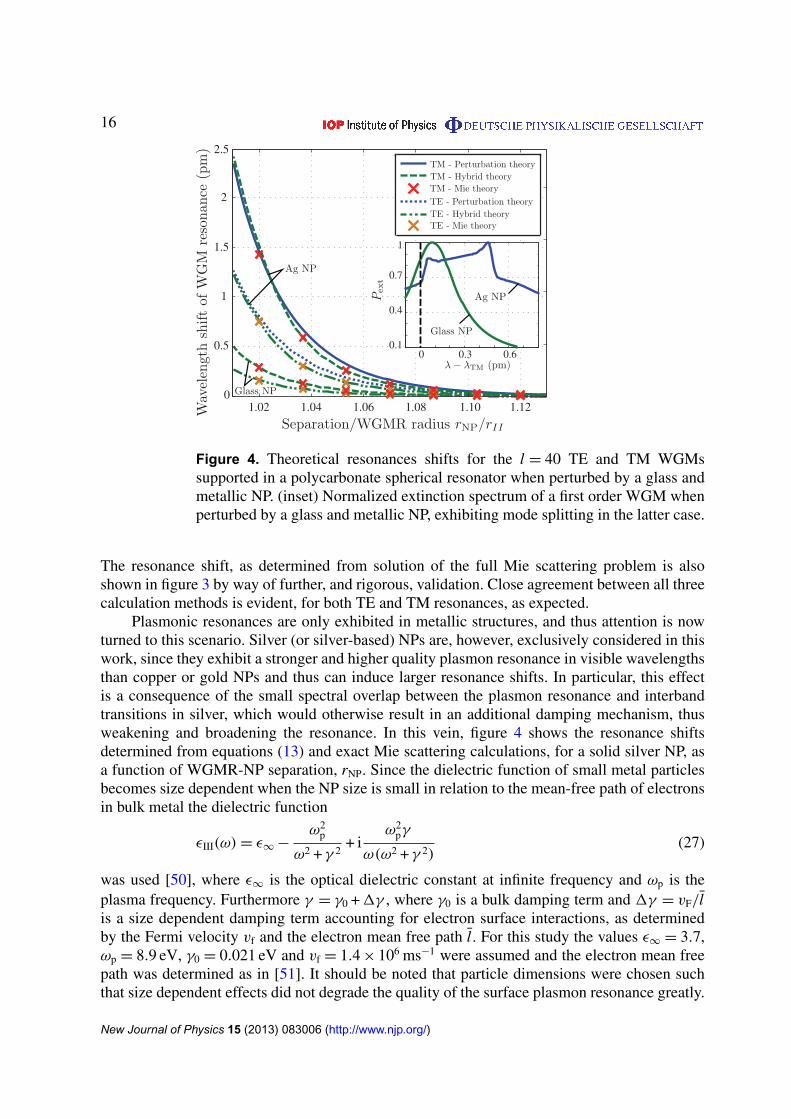
Figure 4. Theoretical resonances shifts for the l = 40 TE and TM WGMssupported in a polycarbonate spherical resonator when perturbed by a glass andmetallic NP. (inset) Normalized extinction spectrum of a first order WGM whenperturbed by a glass and metallic NP, exhibiting mode splitting in the latter case.
The resonance shift, as determined from solution of the full Mie scattering problem is alsoshown in figure 3 by way of further, and rigorous, validation. Close agreement between all threecalculation methods is evident, for both TE and TM resonances, as expected.
Plasmonic resonances are only exhibited in metallic structures, and thus attention is nowturned to this scenario. Silver (or silver-based) NPs are, however, exclusively considered in thiswork, since they exhibit a stronger and higher quality plasmon resonance in visible wavelengthsthan copper or gold NPs and thus can induce larger resonance shifts. In particular, this effectis a consequence of the small spectral overlap between the plasmon resonance and interbandtransitions in silver, which would otherwise result in an additional damping mechanism, thusweakening and broadening the resonance. In this vein, figure 4 shows the resonance shiftsdetermined from equations (13) and exact Mie scattering calculations, for a solid silver NP, asa function of WGMR-NP separation, rNP. Since the dielectric function of small metal particlesbecomes size dependent when the NP size is small in relation to the mean-free path of electronsin bulk metal the dielectric function
εIII(ω)= ε∞ −ω2
p
ω2 + γ 2+ i
ω2pγ
ω(ω2 + γ 2)(27)
was used [50], where ε∞ is the optical dielectric constant at infinite frequency and ωp is theplasma frequency. Furthermore γ = γ0 +1γ , where γ0 is a bulk damping term and 1γ = vF/lis a size dependent damping term accounting for electron surface interactions, as determinedby the Fermi velocity vf and the electron mean free path l. For this study the values ε∞ = 3.7,ωp = 8.9 eV, γ0 = 0.021 eV and vf = 1.4 × 10⁶ ms−1 were assumed and the electron mean freepath was determined as in [51]. It should be noted that particle dimensions were chosen suchthat size dependent effects did not degrade the quality of the surface plasmon resonance greatly.
New Journal of Physics 15 (2013) 083006 (http://www.njp.org/)

17
Good agreement between all three calculation methods is found once more as expected, withthe silver NP exhibiting more than a four-fold enhancement of the resonance shift of the WGM,with respect to the glass NP.
Finally, and in reference to the inset of figure 4, attention is briefly given to the first radialorder TM mode in a polycarbonate WGMR, with a resonance wavelength of 859.112 nm and aQ factor of ∼1.5 × 10⁷. In particular the inset of figure 4 shows the normalized spectrum aroundthe WGM resonance when both a glass and silver NP are placed close to the WGMR surface.In the former case, line broadening and a shift is evident, in a similar manner to that discussedthus far. For the silver NP, however, mode splitting is evident, therefore highlighting the greaterease with which mode splitting can be observed when using plasmonic NPs. It is important tonote, that the extinction spectra presented in the inset of figure 4 do not correspond to those usedto calculate the shifts depicted in the main panel. Indeed, when mode splitting occurs it is nolonger meaningful to define a WGM resonance shift.
5.2. Core–shell nanoparticles—mode hybridization and level repulsion
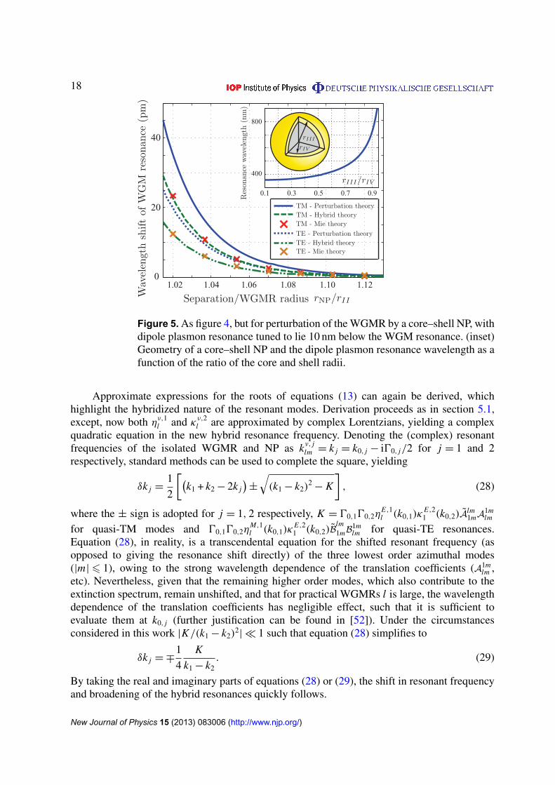
Despite the good agreement seen in the previous section, it should be recognized that thelocalized plasmon resonance of the silver NP lies at a wavelength of 357.477 nm, whilstthe TM and TE WGM resonances considered here occur at wavelengths of 772.459 and782.922 nm respectively. Consequently, the resonance properties of the NP are negligible andthe enhancement of the resonance shift follows by virtue of the off-resonance permittivity. In thiscase, when no mode splitting was evident, perturbation theory was found to give good results inrelation to the more exact theory presented here. Tunability of the plasmon resonance frequencyin core–shell NPs, however, enables further enhancement of the WGM shift, by bringing theplasmon resonance frequency close to the WGM resonance frequency. In so doing, couplingbetween the WGMR and NP is increased due to the increased spectral overlap of the resonances.Coupled resonators, however, imply that each resonator system can no longer be considered inisolation, but instead hybrid WGMR-NP resonant modes must be found. Equations (13) giveprecisely the resonance conditions for such hybrid modes, with the replacement ην,21 → κ
ν,21 .
To first demonstrate the increased coupling strength, and hence larger resonance shifts, theshift in resonance frequency of the l = 40 WGM resonance was calculated, as a core–shell NP(rIII = 55 nm) is brought closer to the WGMR surface and is shown in figure 5. A fused silicacore (nIV = 1.48) and a silver shell were assumed. The dipole plasmon resonance of the NP wastuned to lie 10 nm below the WGM resonance, such that the ratio of the outer to inner radiusf = rIII/rIV was ∼0.9139 and 0.9166 for the TM and TE modes respectively. With referenceto figure 5, an enhancement of the resonance shift of approximately ×60 is apparent, howeverdiscrepances between the first order perturbation results (equation (25)) and those found fromuse of equations (13) are now evident. Disagreement between the two theories results from afailure in the quasi-static approximation to account for retardation effects and spatial variationsof the induced field across the extent of the NP, which can be strong (particularly within the shellnear resonance). Furthermore, the quasi-static approximation does not account for back-actionof the NP upon itself, i.e. multiple scattering effects. Whilst figure 5 shows a>30% discrepancybetween the perturbation theory and hybrid resonance calculations, it should be noted that themagnitude of the difference depends on a number of factors, such as NP dimensions, resonancedetuning and WGM order. Study of these effects is beyond the scope of this paper.
New Journal of Physics 15 (2013) 083006 (http://www.njp.org/)
18
40
20
01.02 1.04 1.06 1.08 1.10 1.12
0.1 0.3 0.5 0.7 0.9
400
800
Figure 5. As figure 4, but for perturbation of the WGMR by a core–shell NP, withdipole plasmon resonance tuned to lie 10 nm below the WGM resonance. (inset)Geometry of a core–shell NP and the dipole plasmon resonance wavelength as afunction of the ratio of the core and shell radii.
Approximate expressions for the roots of equations (13) can again be derived, whichhighlight the hybridized nature of the resonant modes. Derivation proceeds as in section 5.1,except, now both ην,1l and κν,2l are approximated by complex Lorentzians, yielding a complexquadratic equation in the new hybrid resonance frequency. Denoting the (complex) resonantfrequencies of the isolated WGMR and NP as kν, j
lm = k j = k0, j − i00, j/2 for j = 1 and 2respectively, standard methods can be used to complete the square, yielding
δk j =1
2
[(k1 + k2 − 2k j
)±
√(k1 − k2)
2− K
], (28)
where the ± sign is adopted for j = 1, 2 respectively, K = 00,100,2ηE,1l (k0,1)κ
E,21 (k0,2)Alm
1mA1mlm
for quasi-TM modes and 00,100,2ηM,1l (k0,1)κ
E,21 (k0,2)B
lm1mB
1mlm for quasi-TE resonances.
Equation (28), in reality, is a transcendental equation for the shifted resonant frequency (asopposed to giving the resonance shift directly) of the three lowest order azimuthal modes(|m|6 1), owing to the strong wavelength dependence of the translation coefficients (A1m
lm ,etc). Nevertheless, given that the remaining higher order modes, which also contribute to theextinction spectrum, remain unshifted, and that for practical WGMRs l is large, the wavelengthdependence of the translation coefficients has negligible effect, such that it is sufficient toevaluate them at k0, j (further justification can be found in [52]). Under the circumstancesconsidered in this work |K/(k1 − k2)
2| � 1 such that equation (28) simplifies to
δk j = ∓1
4
K
k1 − k2. (29)
By taking the real and imaginary parts of equations (28) or (29), the shift in resonant frequencyand broadening of the hybrid resonances quickly follows.
New Journal of Physics 15 (2013) 083006 (http://www.njp.org/)

19
40
00
80
1.02 1.04 1.06 1.08 1.10 1.12
Figure 6. Theoretical resonances shifts of the j = 1 and 2 TM and TE hybridphotonic–plasmonic modes of a WGMR-NP system as the core–shell NP, withdipole plasmon resonance tuned to lie 10 nm above the isolated WGM resonance,approaches the WGMR.
Inspection of equation (29) reveals two features of interest to biosensing applications (andbeyond). Firstly, and considering only the j = 1 mode, it is evident that if k0,1 > k0,2, thepresence of the NP appears to red shift the WGM, as it approaches the WGMR. Red shifts,of this nature are, for example, seen in figures 4 and 5. However, tunability of the plasmonresonance affords the possibility that k0,1 < k0,2, such that blue shifts can be recorded. To date,observation of blue shifts has only been possible in sensing applications if the refractive indexof the perturbing NP is less than the immersion medium (n I ) [40]; a criteria rarely fulfilled inpractice. Secondly, equation (29) shows that the j = 2 mode is shifted in the opposite senseto the j = 1 mode. Since the j = 2 mode corresponds to the surface plasmon resonance in theisolated NP, equation (29) describes level repulsion between the NP and WGMR as the couplingstrength, K , is increased. Level repulsion of this nature is common to many hybridizationphenomena [53] and is illustrated in figure 6 for a similar situation to the results of figure 5, albeitthe NP resonance is now tuned to lie 10 nm above the WGM resonance. Specifically, blue curvesin figure 5 depict the aggregate shift of the initial WGM, which is towards shorter wavelengths(i.e. blue shifts), whilst the green and black curves show the shift of a single azimuthal mode(|m|6 1), for both j = 1 and 2. Notably, the shifts for the individual |m|6 1 azimuthal modesare larger than typical experimental WGM shifts, however, it is again emphasized that the totalaggregate shift is formed by the superposition of a large number of unshifted modes and a smallnumber of shifted modes as discussed in section 4. Furthermore the shift of the |m|6 1 modeis larger than the initial line-width of the WGM such that mode splitting might be expected.Crucially, however, NP induced losses broaden the WGM to such an extent that this is notthe case. Mode broadening of this form, potentially, allows the domain of perturbation basedcalculations to be extended, albeit care must still be taken if the quasi-static formulation is used.
New Journal of Physics 15 (2013) 083006 (http://www.njp.org/)

20
8
4
0
4
8
4
0
44
0
4
5
15
5
15
5
15
5
15
50
510
0
10
10
0
10
Figure 7. (top middle) Schematic showing definition of Euler angles α and βwhich determine the orientation of the long axis of a cylindrical nanorod. (topleft/right) Spherical polar plot (with polar angles α and β) in which the radiusis given by the magnitude of the resonance shift of the TM/TE WGM (in pm).(bottom row) Polar plots showing cross-sections of the full spherical polar plotsfor rotation of the nanorod in the x–z plane around its short axis, x–y planearound its long axis, y–z plane around its short axis and x–y plane around itsshort axis (left to right). All shifts of the WGM resonance are towards the redend of the spectrum.
As a final point, it is noted that given the plasmon resonance is excited through leakage fromthe WGMR, it is only excited weakly and cannot be easily seen in the extinction spectrum.
5.3. Metallic nanorods—orientational dependence
Similarly to core–shell NPs, nanorods afford the opportunity for tuning of the localized plasmonresonance frequency by variation of the aspect ratio and physical size [42]. Additionally,nanorods also exhibit much stronger near field enhancements than core–shell NPs due to thesharper geometrical features, hence motivating their use in sensing applications. Due to the lack
New Journal of Physics 15 (2013) 083006 (http://www.njp.org/)

21
of spherical symmetry shifts of WGM resonances from nanorods, however, intrinsically showa dependence on the orientation of the nanorod relative to the WGMR surface. As previouslymentioned in sections 3 and 4, rotational symmetry around the polar axis implies that the NPpossesses a T-matrix which is diagonal with respect to m. This is indeed the case for a nanorodaligned parallel to the z-axis, however, if the nanorod is rotated with respect to the z-axis, theT-matrix can have strong off-diagonal elements, necessitating diagonalization of the perturbingmatrix (i.e. ��). Adopting this approach, and assuming the same WGMR parameters as above,the resonance shifts for the l = 40 TM and TE WGM were calculated for perturbation by acylindrical silver nanorod (with radius 25 nm and a length of 125 nm), placed at a distanceof 140 nm from the surface of the WGMR for different nanorod orientations. The nanoroddimensions were selected so as to place the longitudinal plasmon resonance of the nanorodat approximately 758 nm. For simplicity, size dependent effects in the dielectric function weredisregarded for this calculation. An arbitrary rotation of a three-dimensional object can bedescribed by the associated Euler angles (α, β, γ ), however, given the axial symmetry ofnanorods γ can be set to zero without loss of generality. Accordingly the long axis of thenanorod is completely specified by (α, β) as depicted in figure 7 (top-middle). Determinationof the T-matrix of the rotated NP follows by applying the rotation transformation rule to theT-matrix of the unrotated (i.e. parallel to z) nanorod [35]. Numerical results for the resonanceshifts are shown in figure 7, wherein the top left and right panels, present spherical polar surfaceplots, in which the radius at each orientation represents the magnitude of the resonance shift.Due to the relative spectral position of the WGM and plasmon resonances, the WGM resonanceis red-shifted regardless of nanorod orientation. Numerous cross-sections of the surface plotsare also shown in figure 7 (bottom row of polar plots), in which, the radius again represents themagnitude of the resonance shift. In turn, the polar plots represent rotation of the nanorod in thex–z plane around its short axis, x–y plane around its long axis, y–z plane around its short axisand, finally, in the x–y plane around its short axis. Some results have been scaled for clarity,as noted in figure 7. Given that the TM WGM has non-zero electric field components in the xand z directions, whilst the TE WGM only has a non-zero field component in the y direction, itis seen that greater resonance shifts result when the long axis of the nanorod is aligned with anon-zero component of the unperturbed WGM mode. In this case coupling to the longitudinalplasmon resonance is high, such that resonance shifts are larger, in accordance with physicalintuition. Interestingly, it should be noted that if the long axis of the nanorod is orthogonal to anon-zero field component, non-zero shifts can still result due to the off-resonance permittivityof the nanorod and weak excitation of the transverse plasmon resonance. Finally, it is againemphasized that good agreement was found between the results presented in figure 7 and thosefound by performing full Mie scattering calculations.
6. Discussion
Theoretical derivations presented in this paper, have sought to describe the effect of metallicNPs upon the resonant modes of larger dielectric spheres, particularly with a view towardsWGM biosensing. Whilst first order perturbation theory gives approximate expressions for aperturbed WGMR (which have seen extensive use and verification in the literature), problemscan result when considering resonant NPs. For example, whilst equation (25) can be computedrapidly, near NP resonances it gives inaccurate predictions due to the implicit quasi-staticapproximation. On the other hand, equation (24) can produce more accurate results, however
New Journal of Physics 15 (2013) 083006 (http://www.njp.org/)

22
this comes at the expense of increased computational burden, since the perturbed field,E′(r), must be determined numerically and subsequently spatially integrated. In an attemptto mitigate these problems, resonance conditions of the hybrid WGMR-NP system weretherefore established based upon rigorous scattering (Lorenz–Mie) theory, from which shiftsin resonance frequency can be easily determined. Specifically the hybrid resonances aredetermined by finding (complex) roots of the system matrix, from which the extinction spectrumcan be determined in an approximate manner. In general, analytical solution of the systemequations is intractable, however approximate closed form analytic formula were established(equations (11)–(13)) by approximating the related eigenvalue equation.
Small NPs, which can be considered as electric dipole scatterers, allow the resonanceconditions to be expressed in a particularly simple form (equations (13)), further facilitatinganalytic analysis. In light of the desire to avoid unnecessary calculations, for example,approximate formulae were derived for the resonance shift and resonance broadening, frominteraction of a NP with a WGMR. It should be noted that the latter represents an advantage overthe first order perturbation calculations. Despite the approximations made, the hybrid resonanceconditions were found to agree well with full Mie scattering calculations.
Given the greater generality of Lorenz–Mie scattering theory, a number of furtheradvantages over first order perturbation theory can be identified. Especially prominent isthe richer array of physical phenomena which can be predicted and described, a number ofwhich have been presented in this work. For example, mode splitting was demonstrated tooccur under less stringent conditions for metallic NPs, than for dielectric NPs. The question,however, still remains, as to the precise criteria for observation of mode splitting, since linebroadening (also describable within the Lorenz–Mie formalism) is also more significant formetallic NPs. Accordingly a balance between reactive (inductive) and resistive coupling mustbe struck to observe splitting. Mode hybridization, and level repulsion, were also seen tonaturally emerge from the derived hybrid resonance conditions. This was, for example, shownto occur between TM and TE WGMs, when cross-polarization mixing was considered (seeequations (16)) and between the WGM and plasmon resonances that can exist in metallic NPs(e.g. equations (28) and (29)). Given the occurrence of level repulsion in a hybrid WGMR-NP system, by careful tuning of the plasmon resonance of the isolated NP (e.g. a core–shellNP), blue shifts of the WGM resonance can be obtained. Within the context of biosensing, thishence presents an immediate means by which detection multiplexing can be achieved. Use of,for example, two different NPs, each functionalized for detection of different biomolecules, anddesigned so as to induce red and blue WGM resonance shifts respectively, allows discriminationof two different biomolecules.
Finally, Lorenz–Mie theory provides a natural framework, which can be extended toexploit Waterman’s extended boundary method and thus to describe non-spherical NPs, suchas nanorods and nanocubes. In this vein, a study of the dependence of resonance shifts onnanorod orientation was presented. Whilst for more common NP geometries numerous efficientcodes already exist, it should be noted that ill conditioning and/or poor convergence mayhamper determination of the T-matrix for more exotic geometries. Moreover, algorithms forcalculation of the T-matrix, must allow for complex frequencies, since solutions to the resonancecondition are found on the complex plane. Fortunately, this, in principle, does not require anymajor additional coding efforts to be made. In the context of biosensing, knowledge of thedependence of resonance shifts on orientation of asymmetric nanorods affords the possibility oforientational binding studies. For example, by monitoring resonance shifts in both the TE and
New Journal of Physics 15 (2013) 083006 (http://www.njp.org/)

23
TM polarization channels, and with a priori knowledge regarding the nanorod properties, theorientation of a perturbing nanorod can be inferred. This, however, remains as future work.
Appendix A. Definition of the Mie modes
The electric fields of the electric and magnetic multipole fields, or Mie modes, can be expressedin terms of spherical field components (Er , Eθ , Eφ) as [54]
EE( j)lm (r)=
l(l + 1) h( j)
l (kr)r Y m
l (θ, φ)
1r
ddr (rh( j)
l (kr)) ∂∂θ
Y ml (θ, φ)
imr sin θ
ddr (rh( j)
l (kr))Y ml (θ, φ)
, (A.1a)
EM( j)lm (r)=
0
ik2 msin θ h( j)
l (kr)Y ml (θ, φ)
−k2h( j)l (kr) ∂
∂θY m
l (θ, φ)
, (A.1b)
where h( j)l (kr) can be either a spherical Hankel ( j = 1, 2) or a spherical Bessel ( j = 3) function.
Y ml (θ, φ) are the spherical harmonics of order l = 1, 2, 3, . . ., m = −l,−l + 1, . . . , l defined by
Y ml (θ, φ)=
[(2l + 1)(l − m)!
4π(l + m)!
]1/2
Pml (cos θ) exp(imφ), (A.2)
where Pml (·) are the associated Legendre polynomials. The multipole modes depend on
the material properties via the constants k1 = iωε− σ/ω, k2 = iωµ, where k2= −k1k2, ε is
the permittivity of the medium, µ is the permeability and σ is the conductivity [55]. Thecorresponding magnetic fields are given by HM( j)
lm (r)= EE( j)lm (r) and HE( j)
lm (r)= −k1k2
EM( j)lm (r).
Appendix B. Mie expansions in shifted coordinate systems
Consider two coordinate systems in which a point is described by the position vectors r andr′ respectively, where r′
= r − rNP (see figure 1). Any field can be represented using Mieexpansions in both coordinate systems. Consider representing a field E(r) in terms of Mie modescentred on r = 0 and r′
= 0, such that
E(r)=
∑l,m
aElmEE( j)
lm (r)+ aMlmEM
lm(r) (B.1a)
=
∑L ,M
aEL MEE( j ′)
L M (r′)+ aML MEM( j ′)
L M (r′). (B.1b)
Noting the relations [35]
EE( j)lm (r)=
∑L ,M
Alm( j ′′)
L M (rNP)EE( j ′)
L M (r′)+k
k2Blm( j ′′)
L M (rNP)EM( j ′)
L M (r′), (B.2a)
EM( j)lm (r)=
∑L ,M
Alm( j ′′)
L M (rNP)EM( j ′)
L M (r′)+k2
kBlm( j ′′)
L M (rNP)EE( j ′)
L M (r′) (B.2b)
New Journal of Physics 15 (2013) 083006 (http://www.njp.org/)

24
yields
aEL M =
∑l,m
aElmA
lm( j ′′)
L M (rNP)+k2
kaM
lmBlm( j ′′)
L M (rNP), (B.3a)
aML M =
∑l,m
aMlmA
lm( j ′′)
L M (rNP)+k
k2aE
lmBlm( j ′′)
L M (rNP), (B.3b)
where explicit expressions for the shift coefficients Alm( j ′′)
L M (rNP) and Blm( j ′′)
L M (rNP) can be foundin the work of Xu [56]. Care, however, must be taken with regards to the normalization ofthe Mie modes, and the resulting scaling of the shift coefficients. Specifically, in this work anadditional factor of
√[(2l + 1)(L + M)!(l − m)!]/[(2L + 1)(L − M)(l + m)!], is introduced into
equations (75) and (76) of Xu’s work [56].In this paper a dipole approximation is often made for the scatterer NP, such that
only A1m( j ′′)
lm = A1m( j ′′)
lm (rNP) and Alm( j ′′)
1m = Alm( j ′′)
1m (−rNP) (and similarly for B1m( j ′′)
lm (rNP) andBlm( j ′′)
1m (−rNP)) need to be considered. It can then be shown that[Alm( j ′′)
1m
Blm( j ′′)
1m
]=
2
l(l + 1)
[A1m( j ′′)
lm
−B1m( j ′′)
lm
], (B.4)
where
A1m( j ′′)
lm =l(l + 1)
2(1 + m)!
[3
(2l + 1)
(l − m)!
(1 − m)!
(1 + m)!
(l + m)!
]1/2 [(l + m)!
l!h( j ′′)
l−1 (krNP)+(−1)m l!
(l − m)!h( j ′′)
l+1 (krNP)
](B.5)
and
B1m( j ′′)
lm =im
2
[3
(2l + 1)
(l − m)!
(1 − m)!
(l + m)!
(1 + m)!
]1/2(2l + 1)
(l − 1)!h( j ′′)
l (krNP). (B.6)
The correct choice of j ′ and j ′′ is dependant on the position at which the field is to be evaluated.Specifically it is noted that j ′
= 3, j ′′= j for r ′ < rNP and j ′
= j , j ′′= 3 for r ′ > rNP.
Appendix C. Scaling parameter for a core–shell nanoparticle
The mode coefficients for the field scattered from a core–shell NP are given (analogously toequation (3c)) by dνlm = κνl (k
I, kIII, k I V , rIII, rIV)bνlm where kIII and kIV denote the wavenumberin the shell and core regions respectively, which have radii rIII and rIV (see figure 5). Using theshorthand notation zi
j = kir j and letting κν,2l = κνl (kI, kIII, k I V , rIII, rIV) it is possible to show
κν,2l =
kIs8
νl (z
IIIIII)h
(3)l (z
IIII)− kIII
s H νl (z
IIIIII)ψ
(3)l (zI
III)
kIIIs H ν
l (zIIIIII)ψ
(1)l (zI
III)− kIs8
νl (z
IIIIII)h
(1)l (z
IIII)
(C.1)
with s = 1 or 2 for ν = E or M respectively, where
8νl (z)= ψ
(2)l (z)τ ν,2l +ψ (1)
l (z)µν,2l , (C.2a)
H νl (z)= h(2)l (z)τ
ν,2l + h(1)l (z)µ
ν,2l (C.2b)
New Journal of Physics 15 (2013) 083006 (http://www.njp.org/)

25
and
τν,2l =
kIVs ψ
(1)l (zIII
IV)h(3)l (z
IVIV)− kIII
s h(1)l (zIIIIV)ψ
(3)l (zIV
IV)
kIIIs h(2)l (z
IIIIV)ψ
(1)l (zIII
IV)− kIIIs ψ
(2)l (zIII
IV)h(1)l (z
IIIIV), (C.3a)
µν,2l =
kIIIs ψ
(3)l (zIV
IV)h(2)l (z
IIIIV)− kIV
s h(3)l (zIVIV)ψ
(2)l (zIII
IV)
kIIIs h(2)l (z
IIIIV)ψ
(1)l (zIII
IV)− kIIIs ψ
(2)l (zIII
IV)h(1)l (z
IIIIV). (C.3b)
Appendix D. Derivation of equation (23)
To derive equation (23) it is sufficient to start from equation (5) (with omission of the m subscriptas described in section 2), whereby some minor rearrangement yields[
bE
bM
]=
[N
E,1O
O NM,1
]{[aE
aM
]+
[�1 �3
�4 �2
][bE
bM
]}which can be more concisely written as
b = N(a +�b). (D.1)
Left multiplying by � and collecting terms subsequently gives �b = [I−�N]−1�Na, which
upon back substitution into equation (D.1) yields
b = N(a + [I−�N]−1�Na). (D.2)
If the off diagonal blocks of � (i.e. �3 and �4) are neglected equation (D.2) is blockdiagonal allowing separation into two independent matrix equations, namely those specifiedby equation (23).
References
[1] Giannini V, Fernandez-Domınguez A I, Heck S C and Maier S A 2011 Plasmonic nanoantennas: fundamentalsand their use in controlling the radiative properties of nanoemitters Chem. Rev. 111 3888–912
[2] Lal S, Link S and Halas N J 2007 Nano-optics from sensing to waveguiding Nature Photon. 1 3641–48[3] Maier S 2007 Plasmonics: Fundamentals and Applications (Berlin: Springer)[4] Homola J 2008 Surface plasmon resonance sensors for detection of chemical and biological species Chem.
Rev. 108 462–93[5] Homola J 2006 Surface Plasmon Resonance Based Sensors (Springer Series on Chemical Sensors and
Biosensors vol 4) (Berlin: Springer)[6] Min B, Ostby E, Sorger V, Ulin-Avila E, Yang L, Zhang X and Vahala K 2009 High-Q surface-plasmon-
polariton whispering-gallery microcavity Nature 457 455–8[7] Anker J N, Hall W P, Lyandres O, Shah N C, Zhao J and Van Duyne R P 2008 Biosensing with plasmonic
nanosensors Nature Mater. 7 442–53[8] Mayer K M and Hafner J H 2011 Localized surface plasmon resonance sensors Chem. Rev. 111 3828–57[9] Baaske M and Vollmer F 2012 Optical resonator biosensors: molecular diagnostic and nanoparticle detection
on an integrated platform Chem. Phys. Chem. 13 427–36[10] Gorodetsky M L, Savchenkov A A and Ilchenko V S 1996 Ultimate Q of optical microsphere resonators Opt.
Lett. 21 453–5[11] Vollmer F, Arnold S and Keng D 2008 Single virus detection from the reactive shift of a whispering-gallery
mode Proc. Natl Acad. Sci. USA 105 20701–4
New Journal of Physics 15 (2013) 083006 (http://www.njp.org/)

26
[12] Arnold S, Keng D, Shopova S, Holler S, Zurawsky W and Vollmer F 2009 Whispering gallery modecarousel—a photonic mechanism for enhanced nanoparticle detection in biosensing Opt. Express17 6230–8
[13] Waldron R A 1960 Perturbation theory of resonant cavities Proc. Inst. Electr. Eng. 107C 272–4[14] Klein O, Ponova S, Dressel M and Greiner G 1993 Microwave cavity perturbation technique: I. Principles
Int. J. Infrared Millim. Waves 14 2423–57[15] Arnold S, Khoshsima M, Teraoka I, Holler S and Vollmer F 2003 Shift of whispering-gallery modes in
microspheres by protein adsorption Opt. Lett. 28 272–4[16] Teraoka I, Arnold S and Vollmer F 2003 Perturbation approach to resonance shifts of whispering-gallery
modes in a dielectric microsphere as a probe of a surrounding medium J. Opt. Soc. Am. B 20 1937–46[17] Teraoka I and Arnold S 2006 Theory of resonance shifts in TE and TM whispering gallery modes by non-
radial perturbations for sensing applications J. Opt. Soc. Am. B 23 1381–9[18] Shopova S I, Rajmangal R, Holler S and Arnold S 2011 Plasmonic enhancement of a whispering-gallery-
mode biosensor for single nanoparticle detection Appl. Phys. Lett. 98 243104[19] Xiao Y-F, Liu Y-C, Li B-B, Chen Y-L, Li Y and Gong Q 2012 Strongly enhanced light–matter interaction in
a hybrid photonic–plasmonic resonator Phys. Rev. A 85 031805[20] Dantham V R, Holler S, Kolchenko V, Wan Z and Arnold S 2012 Taking whispering gallery-mode single
virus detection and sizing to the limit Appl. Phys. Lett. 101 043704[21] Arnold S, Dantham V R, Barbre C, Garetz B A and Fan X 2012 Periodic plasmonic enhancing epitopes on a
whispering gallery mode biosensor Opt. Express 20 26147–60[22] Santiago-Cordoba M A, Cetinkaya M, Boriskina S V, Vollmer F and Demirel M C 2012 Ultrasensitive
detection of a protein by optical trapping in a photonic–plasmonic microcavity J. Biophoton. 10 1–10[23] Lin S and Crozier K B 2013 Trapping-assisted sensing of particles and proteins using on-chip optical
microcavities ACS Nano 7 1725–30[24] Santiago-Cordoba M A, Boriskina S V, Vollmer F and Demirel M C 2011 Nanoparticle-based protein
detection by optical shift of a resonant microcavity Appl. Phys. Lett. 99 073701[25] Witzens J and Hochberg M 2011 Optical detection of target molecule induced aggregation of nanoparticles
by means of high-Q resonators Opt. Express 19 7034–61[26] Dantham V R, Holler S, Kolchenko V, Wan Z and Arnold S 2013 Microcavity single virus detection and
sizing with molecular sensitivity Proc. SPIE 8600 86001P[27] Hao E and Schatz G C 2004 Electromagnetic fields around silver nanoparticles and dimers J. Chem. Phys.
120 357–66[28] Weiss D S, Sandoghdar V, Hare J, Lefevre-Seguin V, Raimond J M and Haroche S 1995 Splitting of high-Q
Mie modes induced by light backscattering in silica microspheres Opt. Lett. 20 1835–7[29] Deych L and Rubin J 2009 Rayleigh scattering of whispering gallery modes of microspheres due to a single
dipole scatterer Phys. Rev. A 80 061805[30] Waterman P C 1969 New formulation of acoustic scattering J. Acoust. Soc. Am. 45 1417–29[31] Gouesbet G and Grehan G 1999 Generalized Lorenz–Mie theory for assemblies of spheres and aggregates
J. Opt. A: Pure Appl. Opt. 1 706–71[32] Vollmer F and Arnold S 2008 Whispering-gallery-mode biosensing: label-free detection down to single
molecules Nature Methods 5 591–6[33] Deych L, Schmidt S, Chipouline A, Pertsch T and Tunnermann A 2008 Optical coupling of fundamental
whispering-gallery modes in bispheres Phys. Rev. A 77 051801[34] Mishchenko M I 2000 Calculation of the amplitude matrix for a nonspherical particle in a fixed orientation
Appl. Opt. 39 1026–31[35] Mishchenko M I, Travis L D and Lacis A A 2002 Scattering, Absorption and Emission of Light by Small
Particles (Cambridge: Cambridge University Press)[36] Moroz A 2005 Improvement of Mishchenko’s T matrix code for absorbing particles Appl. Opt. 44 3605–9[37] Bohren C F and Huffman D R 1998 Absorption and Scattering of Light by Small Particles (Weinheim: Wiley)
New Journal of Physics 15 (2013) 083006 (http://www.njp.org/)

27
[38] van de Hulst H C 1981 Light Scattering by Small Particles (Mineola, NY: Dover Publications)[39] Gasiorowicz S 2003 Quantum Physics 3rd edn (New York: Wiley)[40] Rubin J T and Deych L 2010 Ab initio theory of defect scattering in spherical whispering-gallery-mode
resonators Phys. Rev. A 81 053827[41] Halas N 2002 The optical properties of nanoshells Opt. Photon. News 13 26–30[42] Huang H, Yu C, Chang H, Chiu K, Ming H Chen, Liu R and Tsai D 2007 Plasmonic optical properties of a
single gold nano-rod Opt. Express 15 7132–9[43] Zhou Z-K, Peng X-N, Yang Z-J, Zhang Z-S, Li M, Su X-R, Zhang Q, Shan X, Wang Q-Q and Zhang Z 2011
Tuning gold nanorod–nanoparticle hybrids into plasmonic Fano resonance for dramatically enhanced lightemission and transmission Nano. Lett. 11 49–55
[44] Mackowski D W, Altenkirch R A and Menguc M P 1990 Internal absorption cross sections in a stratifiedsphere Appl. Opt. 29 1551–9
[45] Mackowski D W 1991 Analysis of radiative scattering for multiple sphere configurations Proc. R. Soc.Lond. A 433 599–614
[46] Teraoka I and Arnold S 2009 Resonance shifts of counter-propagating whispering-gallery modes: degenerateperturbation with axial symmetry J. Opt. Soc. Am. B 26 1321–9
[47] Johnson B R 1993 Theory of morphology-dependent resonances: shape resonances and width formulas J.Opt. Soc. Am. A 10 343–52
[48] Schiller S 1993 Asymptotic expansion of morphological resonance frequencies in Mie scattering Appl. Opt.32 2181–5
[49] Lam C C, Leung P T and Young K 1992 Explicit asymptotic formulas for the positions, widths and strengthsof resonances in Mie scattering J. Opt. Soc. Am. B 9 1585–92
[50] Kreibig U 1974 Electronic properties of small silver particles: the optical constants and their temperaturedependence J. Phys. F: Metal Phys. 4 999–1014
[51] Miao X, Brener I and Luk T S 2010 Nanocomposite plasmonic fluorescence emitters with core/shellconfigurations Opt. J. Soc. Am. B 27 1561–70
[52] Foreman M R and Vollmer F 2013 Level repulsion in hybrid photonic–plasmonic microresonators forenhanced biodetection, in preparation
[53] Novotny L 2010 Strong coupling, energy splitting and level crossings: a classical perspective Am. J. Phys.78 1199–201
[54] Foreman M R, Sivan Y, Maier S A and Torok P 2012 Independence of plasmonic near-field enhancements toillumination beam profile Phys. Rev. B 86 155441
[55] Born M and Wolf E 1980 Principles of Optics 7th edn (Cambridge: Cambridge University Press)[56] Xu Y-L 1996 Calculation of the addition coefficients in electromagnetic multisphere-scattering theory
J. Comput. Phys. 127 285–98
New Journal of Physics 15 (2013) 083006 (http://www.njp.org/)