pdf disponível para download
TRANSCRIPT
ENGENHARIA DE TRANSPORTESVIAS DE COMUNICAÇÃO
TRANSPORTATION ENGINEERING HIGHWAYS, RAILROADS AND AIRPORTS
PT EN
ENGENHARIA DE TRANSPORTESVIAS DE COMUNICAÇÃO
TRANSPORTATION ENGINEERING HIGHWAYS, RAILROADS AND AIRPORTS
PT EN

INTRODUÇÃO INTRODUCTION
# 0101.165.029 AUTO-ESTRADA A10 E NÓ DE INTERLIGAÇÃO à AUTO-ESTRADA DO NORTE (A1) A10 MOTORWAY AND THE INTERCHANGEWITH THE A1 NORTH MOTORWAY
# 0101.114.38/39 VIA RÁPIDA MACHICO/CANIÇAL MACHICO/CANIÇAL MOTORWAY
# 0505.229.008 AUTO-ESTRADA A10 BUCELAS/CARREGADO TúNEL DE MATO FORTE A10 BUCELAS/CARREGADO MOTORWAY MATO FORTE TUNNEL
# 0404.585.002 CONSTRUÇÃO DA NOVA LIGAÇÃO VASCO GIL/FUNDOA à COTA 500 (1A E 2A FASE) NEW ROAD LINK VASCO GIL/FUNDOA, AT 500M HIGH FROM OCEAN LEVEL (1ST AND 2ND PHASE)
# 0101.496.002 AUTO-ESTRADA A17, MARINHA GRANDE/MIRA SUBLANÇO TOCHA/MIRA MARINHA GRANDE/MIRA, A17 FREEWAY,SUBSECTION TOCHA/MIRA
# 0101.229.015 REABILITAÇÃO DA VIA VITORINO NEMÉSIO, AÇORES VITORINO NEMÉSIO ROAD REHABILITATION TERCEIRA ISLAND, AzORES
# 0505.266.007 AUTO-ESTRADA MARRAQUEXE/AGADIRTúNEL zAOUIAT AIT MELLALMARRAKESH/AGADIR MOTORWAYzAOUIAT AIT MELLAL TUNNEL
# 0101.128.079LIGAÇÃO EM VIA EXPRESSO AO PORTO DO FUNCHAL, MADEIRA EXPRESSWAY LINK TO FUNCHAL’ HARBOUR, MADEIRA ISLAND
# 0101.494.001LIGAÇÃO FERROVIÁRIA DE ALTA VELOCIDADE ENTRE LISBOA E PORTO. LOTE C1 – TROÇO ALENQUER (OTA)/POMBAL LISBOA/PORTO HIGH SPEED RAILWAY LINE. SECTION C1 – ALENQUER (OTA)/POMBAL
# 0101.619.001LINHA FERROVIÁRIA DE ALTA VELOCIDADE, EIXO LISBOA/MADRID, TROÇO POCEIRÃO/CAIA LISBON/MADRID HIGH SPEED RAILWAY LINE, POCEIRÃO/CAIA SECTION
# 0502.324.003ESTAÇÃO DE METRO DO TERREIRO DO PAÇO TERREIRO DO PAÇO METRO STATION
#0505.490.003PROLONGAMENTO DA LINHA VERMELHA– ORIENTE/AEROPORTOMETRO RED-LINE EXTENSION– ORIENTE/AEROPORTO
#0505.229.021METRO DE ARGEL, LINHA 1 – EXTENSÃO 2ALGIERS METRO LINE 1 – EXTENSION 2
#0505.380.001METRO LIGEIRO DO PORTO ESTAÇÕES DE 24 DE AGOSTO, HEROÍSMO E S. BENTO PORTO LIGHT RAIL SYSTEM24 AGOSTO, HEROÍSMO AND S. BENTO STATIONS
#0101.342.001AEROPORTO DO PICO. ELABORAÇÃO DO PROJECTO DE AMPLIAÇÃO DA PISTA 10-28, AÇORESPICO’S AIRPORT. RUNWAY 10-28 EXTENSION PROJECT, AzORES
#0106.609.001REABILITAÇÃO DO AEROPORTO DE UIGE, ANGOLA REHABILITATION OF UIGE’S AIRPORT, ANGOLA
# 0101.165.052/055A5 – AUTO-ESTRADA DA COSTA DO ESTORIL, SUBLANÇOS ESTÁDIO NACIONAL A CARCAVELOS. ALARGAMENTO E BENEFICIAÇÃO PARA 2X4 VIAS A5 – COSTA DO ESTORIL FREEWAY, ESTÁDIO NACIONAL TO CARCAVELOS SUBSECTIONS. IMPROVEMENT AND ENLARGEMENT FOR 2X4 LANES
# 0404.585.003VIA RÁPIDA CÂMARA DE LOBOS /ESTREITO DE CÂMARA DE LOBOS CÂMARA DE LOBOS, CÂMARA DE LOBOS/STRAIT EXPRESSWAY
# 0303.333.009HE 470 – TROÇO BARREIRO/PINHAL NOVO (EXCLUSIVE), ELECTRIFICAÇÃO E MODERNIzAÇÃO DAS ESTAÇÕES E APEADEIROSHE 470 – BARREIRO/PINHAL NOVO SECTION ELECTRIFICATION AND MODERNIzATION OF STATIONS AND WAY STATIONS
# 0505.274.004 LINHA DO MINHO, TúNEL DA VARIANTE DA TROFAMINHO RAIL, WAY LINE TROFA’S BYPASS TUNNEL
# 0303.333.010 LINHA DA BEIRA BAIXA, TROÇO CASTELO BRANCO/COVILHÃ . MODERNIzAÇÃO DO SUBTROÇO VALE DE PRAzERES/COVILHÃ BEIRA BAIXA RAILWAY LINE. CASTELO BRANCO/COVILHÃ SECTION. MODERNIzATION OF THE VALE DE PRAzERES/COVILHÃ SUBSECTION
# 0505.326.003OBRAS DE REBAIXAMENTO DA VIA FÉRREANO ATRAVESSAMENTO DA CIDADE DE ESPINHOLOWERING WORKS OF THE RAILWAYCROSSING THE CITY OF ESPINHO
# 0303.333.008PROJECTO DE MODERNIzAÇÃO DA LINHA DO NORTE. SUB-TROÇO 3.2 – QUINTANS/OVAR MODERNIzATION OF THE NORTHERN RAILWAY LINE. SUB-SECTION 3.2 – QUINTANS/OVAR
# 0303.333.009HE 479 – EMPREITADA DE CONCEPÇÃO /CONSTRUÇÃO DA PASSAGEM SUPERIOR AO KM 8+512 DA LINHA DO ALENTEJO HE 479 – DESIGN/CONSTRUCTION WORKS OF THE OVERPASS AT KM 8+512 OF ALENTEJO’S RAILWAY LINE
06
10
12
14
16
18
20
22
24
46
48
52
54
56
58
62
64
ESTRADAS E AUTO-ESTRADASHIGHWAYS
26
28
32
34
36
38
40
42
CAMINHOS-DE-FERRO CONVENCIONAISCONVENTIONAL RAILWAYS
AEROPORTOSAIRPORTS
METROPOLITANOSMETRO LINES
LINHAS FERROVIÁRIAS DE ALTA VELOCIDADEHIGH SPEED RAILWAYS
ÍNDICE INDEX
PT EN
®
CENOR Consultores, S.A. was founded in 1980, and has presently a total staff of about 200 employees.
CENOR is an Engineering Consultants company (design and construction supervision), covering different fields of expertise: Renewable Energies, Infrastructures, Water Supply, Wastewater Drainage, Irrigation, Transportation, Industrial Building and Parks, Geotechnical Works, Geology, Bridges and Foundations.
CENOR Consultores, S.A. is the holding company of several Portuguese and International enterprises:
CENOR Group companies:ECGPLAN, Engenharia, Gestão e Planeamento, Lda.Madeira Island, Portugal
CENOR, Açores, Lda.Azores Island, Portugal
CENOR, Consultores Angola, Lda.Luanda, Angola
CENOR, ArgéliaAlger, Algeria
CENOR, ColômbiaBogotá, Colômbia
CENOR, IraqueBaghdad, Iraq
Subsidiary Companies:NVISTLisbon, Portugal
CENORVIA MZMaputo, Mozambique
SCCONSULTBelo Horizonte, Brazil
DALANDíli, East Timor
Visit us at www.cenor.pt and get to know a solid company ever more prepared to take on new challenges.
INTRODUÇÃOINTRODUCTION
A CENOR Consultores, S.A. foi fundada em 1980 e congrega, actualmente, cerca de 200 colaboradores.
É uma empresa especializada em Consultoria de Engenharia no âmbito do projecto e da Fiscalização nos seguintes domínios: Energias Renováveis, Infra-estruturas, Hidráulica Agrícola e Urbana, Saneamento Ambiental, Parques e Unidades Industriais, Engenharia de Transportes, Estruturas e Fundações, Geotecnia e Obras de Arte.
A CENOR Consultores, S.A. detém participações em diversas empresas Nacionais e Internacionais.
Empresas Grupo CENOR:ECGPLAN, Engenharia, Gestão e Planeamento, Lda.Madeira, Portugal
CENOR, Açores, Lda.Açores, Portugal
CENOR, Consultores Angola, Lda.Luanda, Angola
CENOR, ArgéliaArgel, Argélia
CENOR, ColômbiaBogotá, Colômbia
CENOR, IraqueBagdá, Iraque
Empresas Participadas:NVISTLisboa, Portugal
CENORVIA MZMaputo, Moçambique
SCCONSULTBelo Horizonte, Brasil
DALANDíli, Timor Leste
Visite-nos em www.cenor.pt e conheça uma empresa cada vez melhor preparada para responder a novos desafios.
PT EN

ESTRADAS E AUTO-ESTRADASHIGHWAYS
PT EN

10 |
ENGE
NH
ARIA
DE
TRAN
SPOR
TES
– VI
AS D
E CO
MUN
ICAÇ
ÃO T
RAN
SPOR
TATI
ON N
GIN
EERI
NG
HIG
HW
AYS
– RA
ILRO
ADS
AND
AIRP
ORTS
#PROJECT
0101165029
PROJECTO 0101.165.029 Lanço da Auto-Estrada A10, entre Arruda dos Vinhos e o Carregado, com 10km de extensão, projectado para uma velocidade base de 120km/h, com um sistema fechado de portagem. O lanço termina num nó, que se destina a assegurar a interligação entre a Auto-Estrada do Norte (A1) e a Auto-Estrada A10, garantindo ainda a continuidade da circulação para nascente cruzando o Tejo através da nova Ponte da Lezíria e ligando na margem esquerda com a A13 (Almeirim/Marateca). Este nó, um verdadeiro “intercambiador” entre dois eixos rodoviários estruturantes, tem um traçado implantado sobre formações aluvionares e de terraços fluviais, razão pela qual os seus ramos se desenvolvem em aterros de pequena altura e em viadutos com fundações indirectas. Complementarmente, na A1, foi integralmente reformulado um nó em trompete, de ligação à rede rodoviária local e à vila do Carregado.
Section of A10 Freeway, between Arruda dos Vinhos and Carregado, with a total length of 10Km, designed for a base speed of 120Km/h, with a closed toll system. This section ends with an interchange that ensures the connection between the Norte Freeway (A1) and the A10 Freeway, thus guaranteeing the traffic continuity towards east, crossing Tagus river through the new Lezíria bridge and linking, in the left margin, with the A13 Freeway (Almeirim/Marateca). This interchange, working like a true interlink between two major road axes, has a layout implanted over alluvial deposits and stream terraces, reason why the ramps were developed in small landfills and in viaducts with indirect foundations.Complementarily, a trumpet interchange was totally redesigned to connect the A1 freeway to the local roads network and Carregado village.
EN
PT AUTO-ESTRADA A10 E NÓ DE INTERLIGAÇÃO À AUTO-ESTRADA DO NORTE (A1)
A10 MOTORWAY AND THE INTERCHANGE WITH THE A1 NORTH MOTORWAY
CLIENTE_ BRISA – Auto-Estradas de Portugal, SA
SERVIÇOS_ Estudo PrévioProjecto BaseProjecto de Execução Assistência Técnica
INÍCIO_1998
CONCLUSÃO_ 2006
LOCALIZAÇÃO_ Carregado, Portugal
CLIENT_BRISA – Auto-Estradas de Portugal, SA
SERVICES_Preliminary DesignBase ProjectFinal DesignTechnical Assistance
BEGINING_1998
CONCLUSION_2006
LOCATION_ Carregado, Portugal

12 |
ENGE
NH
ARIA
DE
TRAN
SPOR
TES
– VI
AS D
E CO
MUN
ICAÇ
ÃO T
RAN
SPOR
TATI
ON N
GIN
EERI
NG
HIG
HW
AYS
– RA
ILRO
ADS
AND
AIRP
ORTS
# O troço da Via Rápida entre Machico e o Caniçal possui uma extensão total de cerca de 7,1km, com secções a céu aberto e em túnel, e tem um perfil transversal tipo constituído por uma plataforma de 2x2 vias, de 18,5m de largura total quando em faixas contíguas e niveladas e de 22,9m quando em faixas separadas e desniveladas. O projecto inclui cinco túneis duplos com secções separadas por um septo central de 16m, tendo cada tubo 9 m de largura útil que integra uma plataforma com duas vias unidireccionais, bermas e passeios. O Túnel Duplo do Caniçal atravessa o maciço que separa Machico do Caniçal, tem 2.100m de comprimento, galerias pedonais de evacuação de emergência cada 200m e é dotado dos mais recentes equipamentos de sinalização e segurança nomeadamente detecção e combate a incêndio, iluminação e ventilação. O projecto integra ainda três nós desnivelados de ligação à rede viária urbana existente, nove restabelecimentos de extensão total igual a 2200m, três obras de arte especiais (um viaduto e duas pontes) e obras de arte correntes. Especialidades envolvidas: Traçado e Terraplenagens, Drenagem transversal e longitudinal com 10 passagens hidráulicas circulares e 4 rectangulares, Pavimentação, Vedações e Integração Paisagística, Geologia e Geotecnia (20 estruturas de contenção), Rede de Incêndio, infraestruturas de Iluminação, Telecomunicações e de Alimentação de Energia Eléctrica, Sinalização e Equipamento de Segurança.
The freeway link between Machico and Caniçal has a total length of 7,1Km, with open sky and tunnel sections, having a typical cross section platform of 2x2 lanes with 18,5m large when in contiguous and leveled carriage ways and with 22,9m of total width when in separated and super elevated carriage ways. This project comprises five double tunnels with sections separated by a central septum of 16m, having each tube 9m of useful width, and which integrate a platform with two unidirectional lanes, shoulders and sidewalks. The Caniçal’s Double Tunnel crosses the mountainous region that separates Machico from Caniçal, having a total length of 2.100m and comprising pedestrian emergency evacuation galleries (each 200m) and the most
recent technology concerning signaling and safety, namely detection and fire fighting, lighting and ventilation systems. This project also integrates three separate grade intersections at the local crossroads, nine reestablishments (in a total extension of 2.200m), three special engineering structures (one viaduct and two bridges) and several conventional engineering structures. Engineering specialties involved: Road alignment and earthworks, transversal and longitudinal drainage, paving, fencing and landscape design, geologic and geotechnical investigations (20 retaining walls), fire fighting network, lighting infrastructures, telecommunication and electric power supply, signaling and safety equipment.
PROJECT
0101114038
/039
PROJECTO 0101.114.038 /0101.114.039
EN
PT VIA RÁPIDA MACHICO/CANIÇAL
MACHICO/CANIÇAL MOTORWAY
CLIENTE_ Consórcio Construtora do Tâmega/Zagope/Tecnorocha/Somague
SERVIÇOS_ Projecto de Execução
INÍCIO_2002
CONCLUSÃO_ 2006
LOCALIZAÇÃO_ Ilha da Madeira, Portugal
CLIENT_Consórcio Construtora do Tâmega/zagope/Tecnorocha/Somague
SERVICES_Final Design
BEGINING_2002
CONCLUSION_2006
LOCATION_ Madeira Island, Portugal

14 |
ENGE
NH
ARIA
DE
TRAN
SPOR
TES
– VI
AS D
E CO
MUN
ICAÇ
ÃO T
RAN
SPOR
TATI
ON N
GIN
EERI
NG
HIG
HW
AYS
– RA
ILRO
ADS
AND
AIRP
ORTS
#
Túnel aberto em formações sedimentares, constituído por duas galerias afastadas de cerca de 19m, medidos entre guias interiores, com uma secção de 172m2, um desenvolvimento médio de aproximadamente 260m e uma espessura de recobrimento variando entre 15 e 40m. A secção transversal de cada galeria, com uma largura útil entre hasteais de 1,75m e uma altura máxima de 8,5m, garante a inserção de um perfil transversal rodoviário constituído por uma faixa de rodagem com três vias de tráfego, uma berma exterior com 4m de largura, uma berma interior com 1m de largura e dois passeios que limitam a plataforma. A escavação foi realizada segundo o método NATM, com o revestimento primário constituído por betão projectado e pregagens ou por betão projectado e cambotas treliçadas.
Tunnel cut through sedimentary rock formations made up of two galleries approximately 19m apart, each with a 172m2 cross-section and an average length of roughly 260m. The tunnel covering varies between the minimum and maximum values of 15 and 40m. Each gallery’s cross section, with a usable width between side walls of 1,75m and a maximum height of 8,5m, allows the insertion of a 3 lane road cross-section, an external shoulder with 4m, an internal shoulder with 1m and two sidewalks that limit the platform. The excavation was carried out in accordance with the NATM method, with a primary lining comprising shotcrete and bolts or shotcrete and trussed ribs.
PROJECT
0505299008
PROJECTO 0505.229.008
EN
PT AUTO-ESTRADA A10 BUCELAS/CARREGADO TÚNEL DE MATO FORTE
A10 BUCELAS/CARREGADO MOTORWAY MATO FORTE TUNNEL
CLIENTE_ Consórcio Zagope/Epos/Pavia
SERVIÇOS_ Projecto Base para ConcursoProjecto de ExecuçãoAssessoria Geotécnica
INÍCIO_2002
CONCLUSÃO_ 2004
LOCALIZAÇÃO_ Lisboa, Portugal
CLIENT_Consórcio zagope/Epos/Pavia
SERVICES_Base Project for TenderFinal DesignGeotechnical Consultancy
BEGINING_2002
CONCLUSION_2004
LOCATION_ Lisbon, Portugal

16 |
ENGE
NH
ARIA
DE
TRAN
SPOR
TES
– VI
AS D
E CO
MUN
ICAÇ
ÃO T
RAN
SPOR
TATI
ON N
GIN
EERI
NG
HIG
HW
AYS
– RA
ILRO
ADS
AND
AIRP
ORTS
# A nova Ligação Vasco Gil/Fundoa à Cota 500, é uma nova via com 4.230Km, tendo 7 Túneis, 8 Viadutos, 5 Rotundas, 10 Ligações e 6 Restabelecimentos. A obra está dividida em duas fases, tendo a primeira fase uma extensão de 1.700Km e a segunda 2.530Km.O traçado situa-se na Região Autónoma da Madeira, no concelho do Funchal, atravessando as freguesias de S. António e S. Roque. Os principais números caracterizadores do estudo são: 12 ligações de nível à rede viária existente e 1 ligação paralela, perfazendo cerca de 2.185m de novas ligações; 5 Rotundas; 6 Restabelecimentos da rede viária existente; 7 Túneis (6 do tipo mineiro e 1 do tipo “Top-Down”) e 1 Galeria de Emergência, com extensões totais de cerca de 2.113m; 8 Viadutos com extensão total de cerca de 1.269m; 4 Pontões; 3 Passagens Superiores; 1 Passagem Inferior; 1 Passagem Superior de Peões; 4 Passagens Hidráulicas; Cerca de 55 estruturas de Contenção, das quais 29 se situam na 1ª Fase; 10 Paragens de Autocarro instaladas na secção corrente; Perfil transversal tipo em secção corrente - 1.0 (berma) + 7.0 (faixa de rodagem) + 1.0 (berma); Inclinações máximas em perfil longitudinal da secção corrente de 12% em terrapleno e em viaduto e de 8% em túnel mineiro; Inclinação máxima em perfil longitudinal das ligações de 22% e dos restabelecimentos de 30,2%
The new road link Vasco Gil/Fundoa at 500m high from ocean level has 4 230km, comprising 7 Tunnels, 8 Viaducts, 5 Roundabouts, 10 Road links and 6 Road realignments. This work is divided in 2 phases, having the first one a total extension of 1700Km and the second one 2.530Km. This road link is located at Funchal District, crossing S. António and S. Roque parishes, at Madeira Island. This work major technical characteristics are: 12 links to the existent road and 1 parallel connection, totalling 2.185km of new road links; 5 Roundabouts; 6 Road realignments; 7 Tunnels (6 of underground excavation and 1 cut and cover) and 1 Emergency Gallery, totalling 2.113m of extension; 8 Viaducts (total extension of 2.113m); 4 Culverts, 3 Overpasses and 1 Underpass; 1 Pedestrian Overpass, 4 Hydraulic Passages; 55 Support structures (29 executed in the 1st phase); 10 Bus Stop; Typical cross-section of 1.0 (shoulder) + 7.0 (lanes) + 1.0 (shoulder); Maximum gradient in typical longitudinal section of 12% in levelled ground and viaducts and of 8% in tunnels; Maximum gradient in typical longitudinal section of 22% in road links and of 30.2 % in road realignments.
PROJECT
0404585002
PROJECTO 0404.585.002
EN
PT CONSTRUÇÃO DA NOVA LIGAÇÃO VASCO GIL/FUNDOA À COTA 500 (1ª E 2ª FASE)
NEW ROAD LINK VASCO GIL/FUNDOA, AT 500M HIGH FROM OCEAN LEVEL (1ST AND 2ND PHASE)
CLIENTE_ RAMEDM – Estradas da Madeira, SA
SERVIÇOS_ Assessoria à Fiscalização
INÍCIO_2007
CONCLUSÃO_ Em Curso
LOCALIZAÇÃO_ Ilha da Madeira, Portugal
CLIENT_RAMEDM – Estradas da Madeira, SA
SERVICES_Works’ Supervision Consultancy
BEGINING_2007
CONCLUSION_Ongoing
LOCATION_ Madeira Island, Portugal
18 |
ENGE
NH
ARIA
DE
TRAN
SPOR
TES
– VI
AS D
E CO
MUN
ICAÇ
ÃO T
RAN
SPOR
TATI
ON N
GIN
EERI
NG
HIG
HW
AYS
– RA
ILRO
ADS
AND
AIRP
ORTS
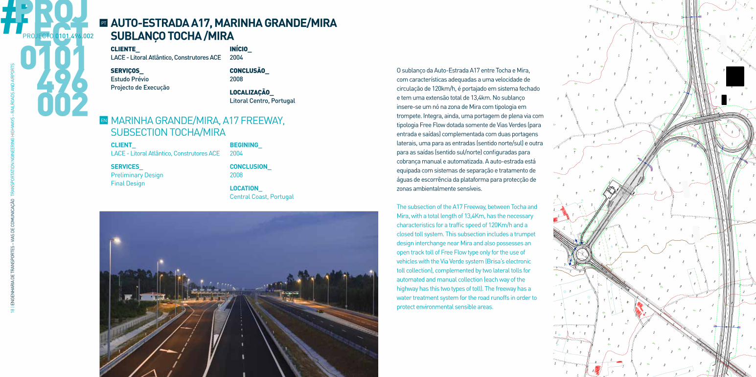
#O sublanço da Auto-Estrada A17 entre Tocha e Mira, com características adequadas a uma velocidade de circulação de 120km/h, é portajado em sistema fechado e tem uma extensão total de 13,4km. No sublanço insere-se um nó na zona de Mira com tipologia em trompete. Integra, ainda, uma portagem de plena via com tipologia Free Flow dotada somente de Vias Verdes (para entrada e saídas) complementada com duas portagens laterais, uma para as entradas (sentido norte/sul) e outra para as saídas (sentido sul/norte) configuradas para cobrança manual e automatizada. A auto-estrada está equipada com sistemas de separação e tratamento de águas de escorrência da plataforma para protecção de zonas ambientalmente sensíveis.
The subsection of the A17 Freeway, between Tocha and Mira, with a total length of 13,4Km, has the necessary characteristics for a traffic speed of 120Km/h and a closed toll system. This subsection includes a trumpet design interchange near Mira and also possesses an open track toll of Free Flow type only for the use of vehicles with the Via Verde system (Brisa’s electronic toll collection), complemented by two lateral tolls for automated and manual collection (each way of the highway has this two types of toll). The freeway has a water treatment system for the road runoffs in order to protect environmental sensible areas.
PROJECT
0101496002
PROJECTO 0101.496.002
EN
PT AUTO-ESTRADA A17, MARINHA GRANDE/MIRA SUBLANÇO TOCHA /MIRA
MARINHA GRANDE/MIRA, A17 FREEWAY, SUBSECTION TOCHA/MIRA
CLIENTE_ LACE - Litoral Atlântico, Construtores ACE
SERVIÇOS_ Estudo PrévioProjecto de Execução
INÍCIO_2004
CONCLUSÃO_ 2008
LOCALIZAÇÃO_ Litoral Centro, Portugal
CLIENT_LACE - Litoral Atlântico, Construtores ACE
SERVICES_Preliminary DesignFinal Design
BEGINING_2004
CONCLUSION_2008
LOCATION_ Central Coast, Portugal

20 |
ENGE
NH
ARIA
DE
TRAN
SPOR
TES
– VI
AS D
E CO
MUN
ICAÇ
ÃO T
RAN
SPOR
TATI
ON N
GIN
EERI
NG
HIG
HW
AYS
– RA
ILRO
ADS
AND
AIRP
ORTS
#
Beneficiação e alargamento da estrada existente entre Angra do Heroísmo e Praia da Vitoria, numa extensão de 17,2km com a introdução de bermas e separador na plataforma 2x2 vias. O projecto inclui a eliminação de todos os entroncamentos com viragens à esquerda e a introdução de três nós desnivelados, três rotundas em secção corrente e oito ligações locais desniveladas, resultando num total de onze passagens superiores. Foi realizada uma rede de caminhos paralelos com 4,5m de largura numa extensão total aproximada de 30km. Especialidades envolvidas: Traçado e Terraplenagens, Geologia e Geotecnia, Obras de Arte Correntes, Drenagem transversal e longitudinal com 40 passagens hidráulicas, Pavimentação com reciclagem do pavimento existente, Obras de Contenção (3 muros de suporte), Vedações e Integração Paisagística com medidas de protecção para passagem de gado Geologia-Geotecnia, infraestruturas de Iluminação, Telecomunicações e de Alimentação de Energia Eléctrica, Sinalização e Equipamento de Segurança.
Improvement and enlargement of the existing road between Angra do Heroísmo and Praia da Vitória, in a total length of 17,2km, introducing shoulders and a median in the 2x2 lanes platform. This project includes the elimination of all at-grade intersections with left turn movement and the introduction of three separate grade interchanges, three roundabouts and eight super elevated road crossings, resulting in a total of eleven overpasses. A parallel network of 4,50m width rural roads was executed, in a total length of 30Km. Engineering specialties involved: Road alignment and earthworks, geological and geotechnical investigation, under and overpasses engineering structures, transversal and longitudinal drainage with 40 hydraulic passages, paving with recycling of the existent pavement, retaining walls, fencing and landscape design with protection measures for cattle passages, lighting and telecommunication infrastructures, electric power supply, signaling and safety equipment.
PROJECT
0101229015
PROJECTO 0101.229.015
EN
PT REABILITAÇÃO DA VIA VITORINO NEMÉSIO, AÇORES
VITORINO NEMÉSIO ROAD REHABILITATION TERCEIRA ISLAND, AzORES
CLIENTE_ Consórcio Zagope/Mota-Engil /Marques
SERVIÇOS_ Projecto Base para Concurso Projecto de Execução
INÍCIO_2006
CONCLUSÃO_ 2009
LOCALIZAÇÃO_ Ilha Terceira, Açores, Portugal
CLIENT_Consórcio zagope/Mota-Engil /Marques
SERVICES_Base Project for TenderFinal Design
BEGINING_2006
CONCLUSION_2009
LOCATION_ Terceira Island, Azores, Portugal
22 |
ENGE
NH
ARIA
DE
TRAN
SPOR
TES
– VI
AS D
E CO
MUN
ICAÇ
ÃO T
RAN
SPOR
TATI
ON N
GIN
EERI
NG
HIG
HW
AYS
– RA
ILRO
ADS
AND
AIRP
ORTS
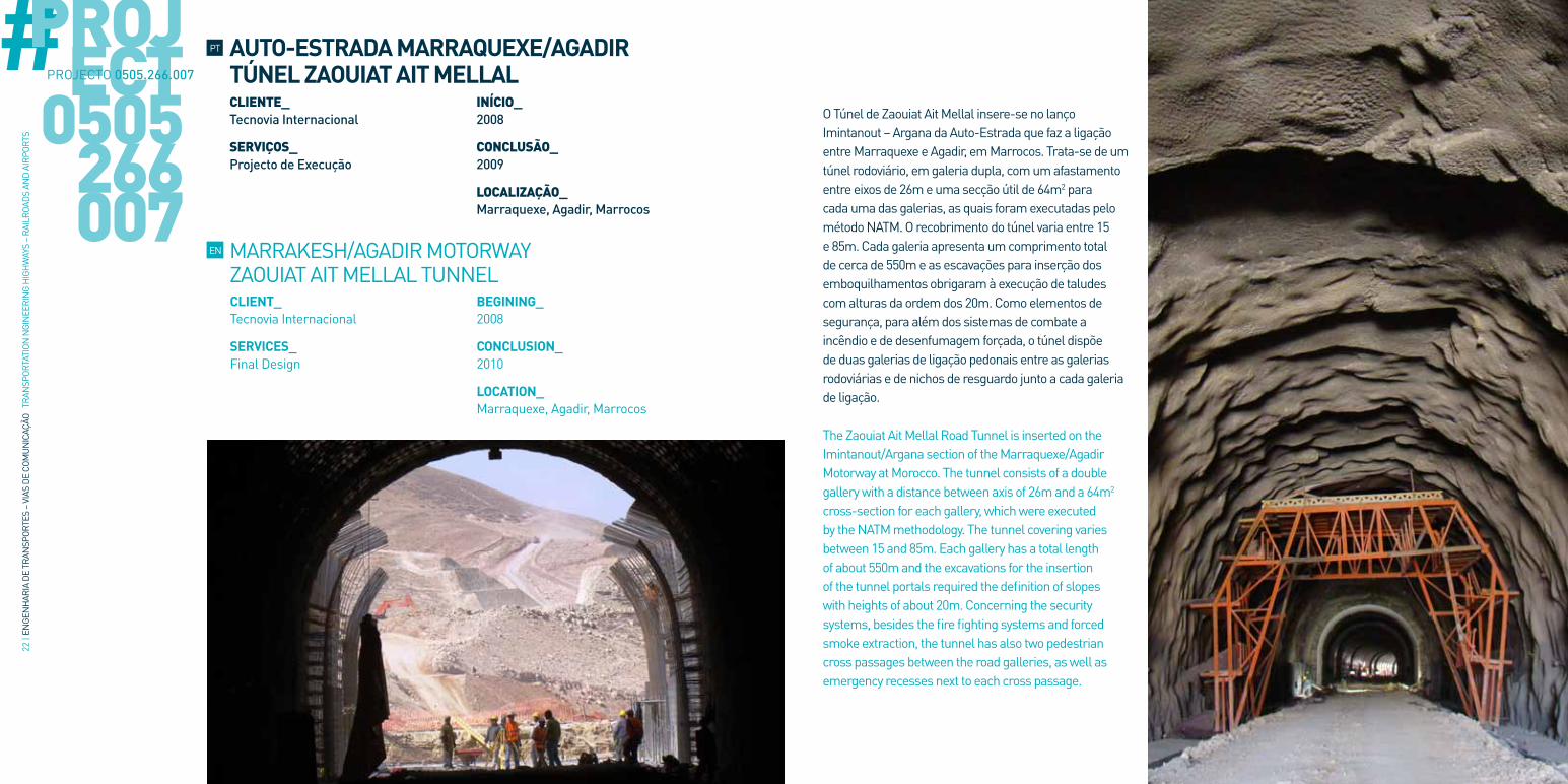
#O Túnel de zaouiat Ait Mellal insere-se no lanço Imintanout – Argana da Auto-Estrada que faz a ligação entre Marraquexe e Agadir, em Marrocos. Trata-se de um túnel rodoviário, em galeria dupla, com um afastamento entre eixos de 26m e uma secção útil de 64m2 para cada uma das galerias, as quais foram executadas pelo método NATM. O recobrimento do túnel varia entre 15 e 85m. Cada galeria apresenta um comprimento total de cerca de 550m e as escavações para inserção dos emboquilhamentos obrigaram à execução de taludes com alturas da ordem dos 20m. Como elementos de segurança, para além dos sistemas de combate a incêndio e de desenfumagem forçada, o túnel dispõe de duas galerias de ligação pedonais entre as galerias rodoviárias e de nichos de resguardo junto a cada galeria de ligação.
The zaouiat Ait Mellal Road Tunnel is inserted on the Imintanout/Argana section of the Marraquexe/Agadir Motorway at Morocco. The tunnel consists of a double gallery with a distance between axis of 26m and a 64m2 cross-section for each gallery, which were executed by the NATM methodology. The tunnel covering varies between 15 and 85m. Each gallery has a total length of about 550m and the excavations for the insertion of the tunnel portals required the definition of slopes with heights of about 20m. Concerning the security systems, besides the fire fighting systems and forced smoke extraction, the tunnel has also two pedestrian cross passages between the road galleries, as well as emergency recesses next to each cross passage.
PROJECT
0505266007
PROJECTO 0505.266.007
EN
PT AUTO-ESTRADA MARRAQUEXE/AGADIR TÚNEL ZAOUIAT AIT MELLAL
MARRAKESH/AGADIR MOTORWAY zAOUIAT AIT MELLAL TUNNEL
CLIENTE_ Tecnovia Internacional
SERVIÇOS_ Projecto de Execução
INÍCIO_2008
CONCLUSÃO_ 2009
LOCALIZAÇÃO_ Marraquexe, Agadir, Marrocos
CLIENT_Tecnovia Internacional
SERVICES_Final Design
BEGINING_2008
CONCLUSION_2010
LOCATION_ Marraquexe, Agadir, Marrocos
24 |
ENGE
NH
ARIA
DE
TRAN
SPOR
TES
– VI
AS D
E CO
MUN
ICAÇ
ÃO T
RAN
SPOR
TATI
ON N
GIN
EERI
NG
HIG
HW
AYS
– RA
ILRO
ADS
AND
AIRP
ORTS
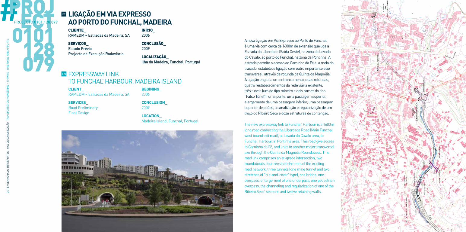
#A nova ligação em Via Expresso ao Porto do Funchal é uma via com cerca de 1600m de extensão que liga a Estrada da Liberdade (Saída Oeste), na zona da Levada do Cavalo, ao porto do Funchal, na zona da Pontinha. A estrada permite o acesso ao Caminho da Fé e, a meio do traçado, estabelece ligação com outro importante eixo transversal, através da rotunda da Quinta da Magnólia. A ligação engloba um entroncamento, duas rotundas, quatro restabelecimentos da rede viária existente, três túneis (um do tipo mineiro e dois ramos do tipo “Falso Túnel”), uma ponte, uma passagem superior, alargamento de uma passagem inferior, uma passagem superior de peões, a canalização e regularização de um troço do Ribeiro Seco e doze estruturas de contenção.
The new expressway link to Funchal’ Harbour is a 1600m long road connecting the Liberdade Road (Main Funchal west bound exit road), at Levada do Cavalo area, to Funchal’ Harbour, in Pontinha area. This road give access to Caminho da Fé, and links to another major transversal axe through the Quinta da Magnólia Roundabout. This road link comprises an at-grade intersection, two roundabouts, four reestablishments of the existing road network, three tunnels (one mine tunnel and two stretches of “cut-and-cover” type), one bridge, one overpass, enlargement of one underpass, one pedestrian overpass, the channeling and regularization of one of the Ribeiro Seco’ sections and twelve retaining walls.
PROJECT
0101128079
PROJECTO 0101.128.079
EN
PT LIGAÇÃO EM VIA EXPRESSO AO PORTO DO FUNCHAL, MADEIRA
EXPRESSWAY LINK TO FUNCHAL’ HARBOUR, MADEIRA ISLAND
CLIENTE_ RAMEDM – Estradas da Madeira, SA
SERVIÇOS_ Estudo PrévioProjecto de Execução Rodoviário
INÍCIO_2006
CONCLUSÃO_ 2009
LOCALIZAÇÃO_ Ilha da Madeira, Funchal, Portugal
CLIENT_RAMEDM – Estradas da Madeira, SA
SERVICES_Road PreliminaryFinal Design
BEGINING_2006
CONCLUSION_2009
LOCATION_ Madeira Island, Funchal, Portugal

26 |
ENGE
NH
ARIA
DE
TRAN
SPOR
TES
– VI
AS D
E CO
MUN
ICAÇ
ÃO T
RAN
SPOR
TATI
ON N
GIN
EERI
NG
HIG
HW
AYS
– RA
ILRO
ADS
AND
AIRP
ORTS
# A A5-Auto-Estrada da Costa do Estoril apresenta um traçado com uma orientação nascente-poente, ligando o centro da cidade de Lisboa ao concelho de Cascais numa extensão total de cerca de 25km. O estudo apresentado refere-se ao alargamento e beneficiação para 2x4 vias de dois sublanços consecutivos da Auto-Estrada (actualmente com 2x3 vias), o Lanço Estádio Nacional / Oeiras e o Lanço Oeiras / Carcavelos, com extensões de 4,1 e 3km respectivamente. A beneficiação inclui a reformulação do Nó do Estádio Nacional que contemplando a reformulação completa de alguns ramos, bem como a introdução de vias de aceleração na entrada da CREL, aumentará significativamente a fluidez e capacidade de escoamento do tráfego graças à eliminação dos movimentos de entrecruzamento existentes. A introdução das quartas vias nos dois sublanços inclui o alargamento dos tabuleiros dos viadutos de Barcarena e Laje.
The A5 Freeway has an East-West orientation and connects Lisbon’s centre to Cascais city, in a total extension of 25Km. The presented study refers to the improvement and enlargement for 2x4 lanes of two consecutive subsections of this freeway (nowadays with 2x3 lanes), the Estádio Nacional/Oeiras and the Oeiras/Carcavelos’ Sections, with lengths of 4,1 and 3Km, respectively. This improvement includes the redesign of the Estádio Nacional Interchange, which, including the complete redesign of some ramps, as well as the introduction of acceleration lanes at CREL’s entrance (Lisbon External Regional Ring), will increase significantly the traffic capacity and fluidity, due to the elimination of some of the existent cross-sections movements. The introduction of the fourth lanes in both subsections comprises the enlargement of the Barcarena and Laje Viaducts’ decks.
PROJECT
0101165052
/055
PROJECTO 0101.165.052 /0101.165.055
EN
PT A5 – AUTO-ESTRADA DA COSTA DO ESTORIL, SUBLANÇOS ESTÁDIO NACIONAL A CARCAVELOS. ALARGAMENTO E BENEFICIAÇÃO PARA 2x4 VIAS
A5 – COSTA DO ESTORIL FREEWAY, ESTÁDIO NACIONAL TO CARCAVELOS SUBSECTIONS. IMPROVEMENT AND ENLARGEMENT FOR 2X4 LANES
CLIENTE_ BRISA – Auto-Estradas de Portugal, SA
SERVIÇOS_ Estudo PrévioProjecto de Execução Rodoviário
INÍCIO_2009
CONCLUSÃO_ Em Curso
LOCALIZAÇÃO_ Oeiras, Lisboa, Portugal
CLIENT_BRISA – Auto-Estradas de Portugal, SA
SERVICES_Road PreliminaryFinal Design
BEGINING_2009
CONCLUSION_Ongoing
LOCATION_ Oeiras, Lisbon, Portugal
28 |
ENGE
NH
ARIA
DE
TRAN
SPOR
TES
– VI
AS D
E CO
MUN
ICAÇ
ÃO T
RAN
SPOR
TATI
ON N
GIN
EERI
NG
HIG
HW
AYS
– RA
ILRO
ADS
AND
AIRP
ORTS
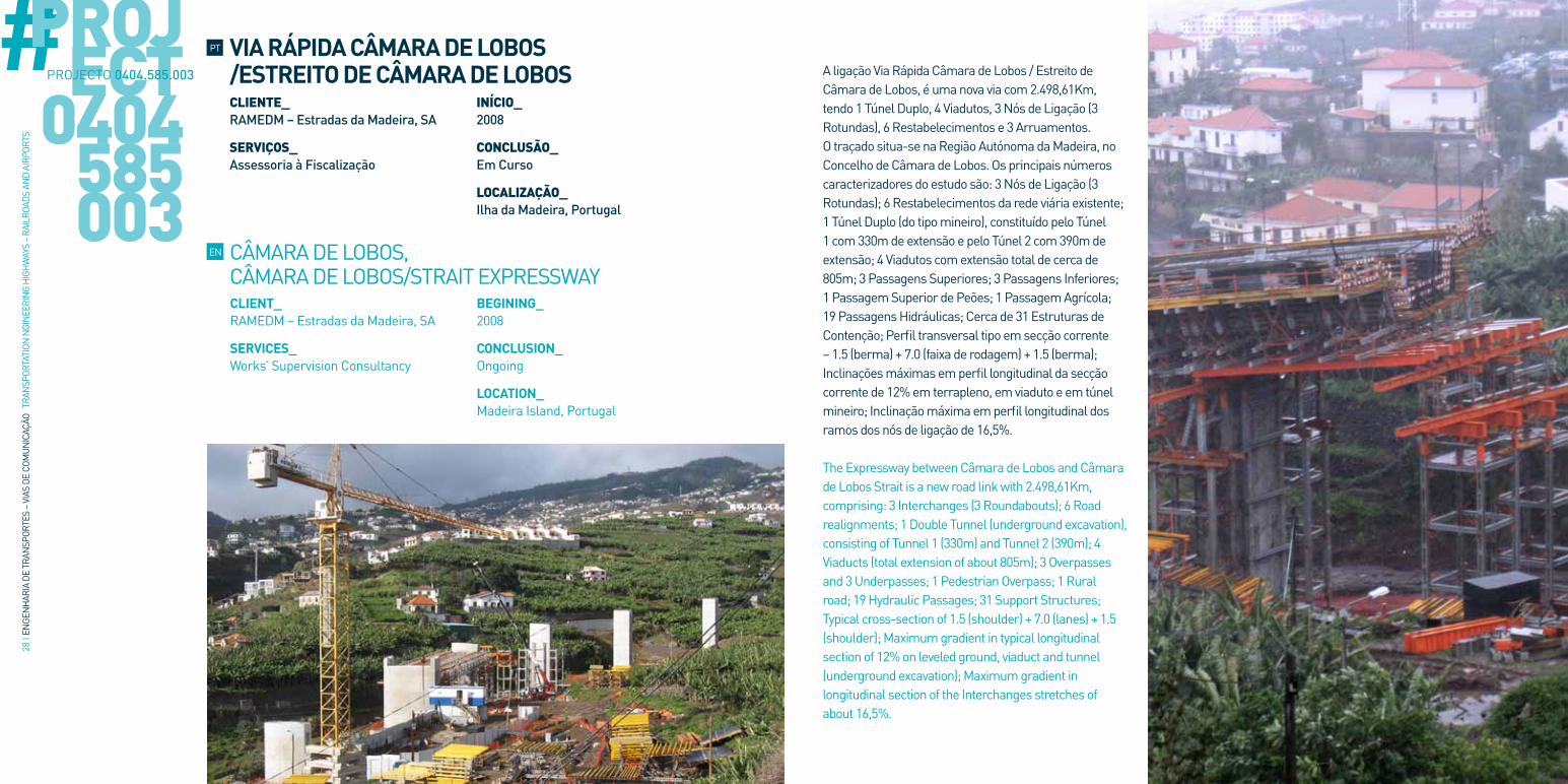
# A ligação Via Rápida Câmara de Lobos / Estreito de Câmara de Lobos, é uma nova via com 2.498,61Km, tendo 1 Túnel Duplo, 4 Viadutos, 3 Nós de Ligação (3 Rotundas), 6 Restabelecimentos e 3 Arruamentos.O traçado situa-se na Região Autónoma da Madeira, no Concelho de Câmara de Lobos. Os principais números caracterizadores do estudo são: 3 Nós de Ligação (3 Rotundas); 6 Restabelecimentos da rede viária existente; 1 Túnel Duplo (do tipo mineiro), constituído pelo Túnel 1 com 330m de extensão e pelo Túnel 2 com 390m de extensão; 4 Viadutos com extensão total de cerca de 805m; 3 Passagens Superiores; 3 Passagens Inferiores; 1 Passagem Superior de Peões; 1 Passagem Agrícola; 19 Passagens Hidráulicas; Cerca de 31 Estruturas de Contenção; Perfil transversal tipo em secção corrente – 1.5 (berma) + 7.0 (faixa de rodagem) + 1.5 (berma); Inclinações máximas em perfil longitudinal da secção corrente de 12% em terrapleno, em viaduto e em túnel mineiro; Inclinação máxima em perfil longitudinal dos ramos dos nós de ligação de 16,5%.
The Expressway between Câmara de Lobos and Câmara de Lobos Strait is a new road link with 2.498,61Km, comprising: 3 Interchanges (3 Roundabouts); 6 Road realignments; 1 Double Tunnel (underground excavation), consisting of Tunnel 1 (330m) and Tunnel 2 (390m); 4 Viaducts (total extension of about 805m); 3 Overpasses and 3 Underpasses; 1 Pedestrian Overpass; 1 Rural road; 19 Hydraulic Passages; 31 Support Structures; Typical cross-section of 1.5 (shoulder) + 7.0 (lanes) + 1.5 (shoulder); Maximum gradient in typical longitudinal section of 12% on leveled ground, viaduct and tunnel (underground excavation); Maximum gradient in longitudinal section of the Interchanges stretches of about 16,5%.
PROJECT
0404585003
PROJECTO 0404.585.003
EN
PT VIA RÁPIDA CÂMARA DE LOBOS /ESTREITO DE CÂMARA DE LOBOS
CÂMARA DE LOBOS, CÂMARA DE LOBOS/STRAIT EXPRESSWAY
CLIENTE_ RAMEDM – Estradas da Madeira, SA
SERVIÇOS_ Assessoria à Fiscalização
INÍCIO_2008
CONCLUSÃO_ Em Curso
LOCALIZAÇÃO_ Ilha da Madeira, Portugal
CLIENT_RAMEDM – Estradas da Madeira, SA
SERVICES_Works’ Supervision Consultancy
BEGINING_2008
CONCLUSION_Ongoing
LOCATION_ Madeira Island, Portugal

CAMINHOS-DE-FERRO CONVENCIONAISCONVENTIONAL RAILWAYS
PT EN
32 |
ENGE
NH
ARIA
DE
TRAN
SPOR
TES
– VI
AS D
E CO
MUN
ICAÇ
ÃO T
RAN
SPOR
TATI
ON N
GIN
EERI
NG
HIG
HW
AYS
– RA
ILRO
ADS
AND
AIRP
ORTS
#
CLIENT_REFER
SERVICES_Consultancy, Supervision and CoordinationAdministrative Management, Control of Costs, Control of Planning, Control of Quality, Control of Safety, Control of Environment
BEGINING_2008
CONCLUSION_2009
LOCATION_ Barreiro, Pinhal Novo, Portugal
HE 470 – BARREIRO/PINHAL NOVO SECTION ELECTRIFICATION AND MODERNIzATION OF STATIONS AND WAY STATIONS
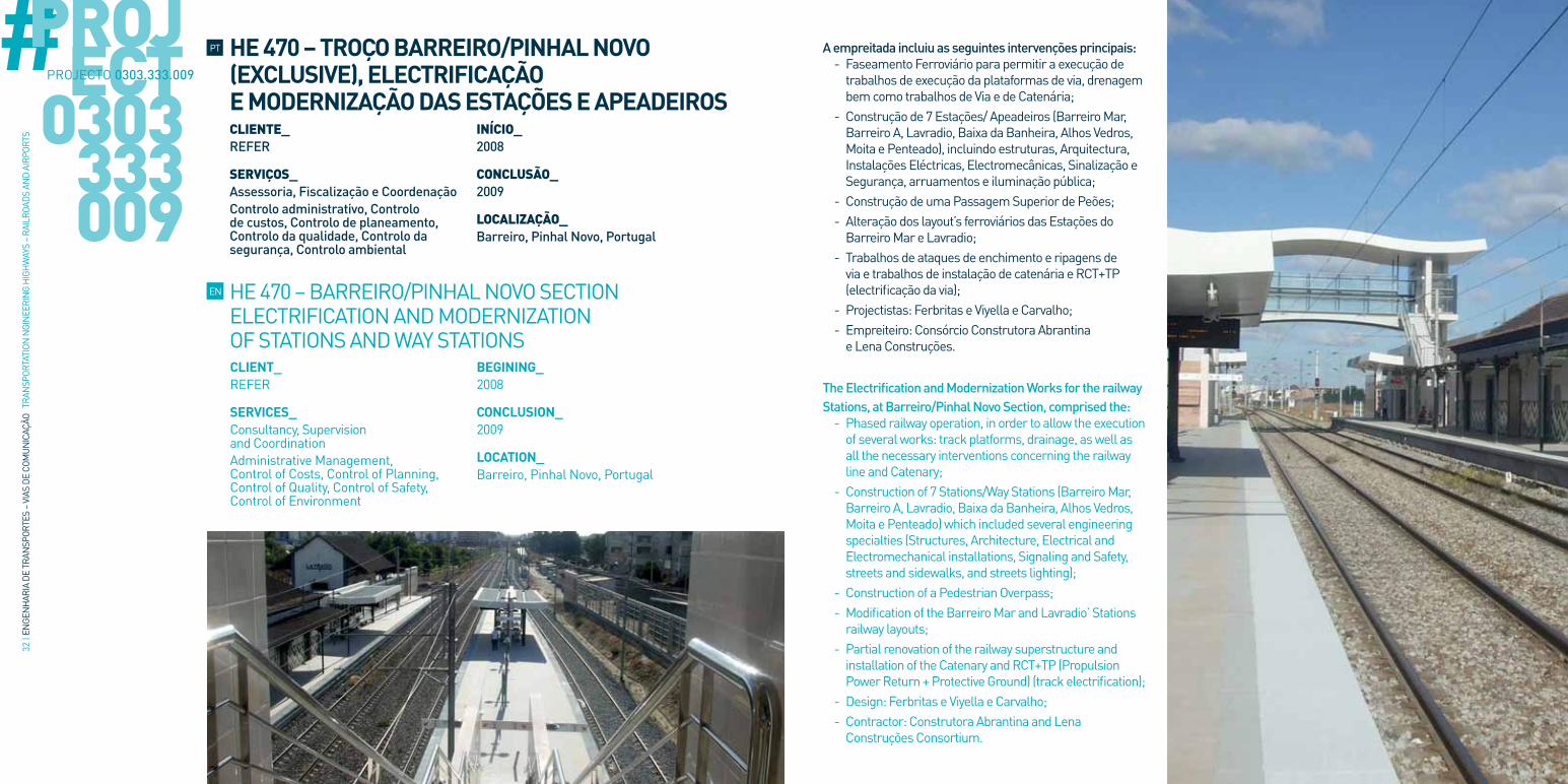
A empreitada incluiu as seguintes intervenções principais: - Faseamento Ferroviário para permitir a execução de trabalhos de execução da plataformas de via, drenagem bem como trabalhos de Via e de Catenária;
- Construção de 7 Estações/ Apeadeiros (Barreiro Mar, Barreiro A, Lavradio, Baixa da Banheira, Alhos Vedros, Moita e Penteado), incluindo estruturas, Arquitectura, Instalações Eléctricas, Electromecânicas, Sinalização e Segurança, arruamentos e iluminação pública;
- Construção de uma Passagem Superior de Peões; - Alteração dos layout’s ferroviários das Estações do Barreiro Mar e Lavradio;
- Trabalhos de ataques de enchimento e ripagens de via e trabalhos de instalação de catenária e RCT+TP (electrificação da via);
- Projectistas: Ferbritas e Viyella e Carvalho; - Empreiteiro: Consórcio Construtora Abrantina e Lena Construções.
The Electrification and Modernization Works for the railway Stations, at Barreiro/Pinhal Novo Section, comprised the:
- Phased railway operation, in order to allow the execution of several works: track platforms, drainage, as well as all the necessary interventions concerning the railway line and Catenary;
- Construction of 7 Stations/Way Stations (Barreiro Mar, Barreiro A, Lavradio, Baixa da Banheira, Alhos Vedros, Moita e Penteado) which included several engineering specialties (Structures, Architecture, Electrical and Electromechanical installations, Signaling and Safety, streets and sidewalks, and streets lighting);
- Construction of a Pedestrian Overpass; - Modification of the Barreiro Mar and Lavradio’ Stations railway layouts;
- Partial renovation of the railway superstructure and installation of the Catenary and RCT+TP (Propulsion Power Return + Protective Ground) (track electrification);
- Design: Ferbritas e Viyella e Carvalho; - Contractor: Construtora Abrantina and Lena Construções Consortium.
PROJECT
0303333009
PROJECTO 0303.333.009
EN
PT HE 470 – TROÇO BARREIRO/PINHAL NOVO (EXCLUSIVE), ELECTRIFICAÇÃO E MODERNIZAÇÃO DAS ESTAÇÕES E APEADEIROS CLIENTE_ REFER
SERVIÇOS_ Assessoria, Fiscalização e CoordenaçãoControlo administrativo, Controlo de custos, Controlo de planeamento, Controlo da qualidade, Controlo da segurança, Controlo ambiental
INÍCIO_2008
CONCLUSÃO_ 2009
LOCALIZAÇÃO_ Barreiro, Pinhal Novo, Portugal

34 |
ENGE
NH
ARIA
DE
TRAN
SPOR
TES
– VI
AS D
E CO
MUN
ICAÇ
ÃO T
RAN
SPOR
TATI
ON N
GIN
EERI
NG
HIG
HW
AYS
– RA
ILRO
ADS
AND
AIRP
ORTS
#O túnel da Variante da Trofa insere-se na Linha do Minho e tem cerca de 1.405m de extensão, dos quais 1.090m são constituídos em escavação subterrânea e o restante desenvolvimento em escavação a céu aberto. O túnel é constituído por uma única galeria com uma largura útil entre hasteais de 10,8m e uma altura máxima de 7m, na qual se inserem duas vias-férreas, uma para cada sentido de tráfego, com um afastamento entre eixos de 4,3m. O túnel atravessa um maciço xistento que apresenta diferentes estados de alteração e graus de fracturação. O recobrimento do túnel varia entre cerca de 4m e cerca de 62m.
The railway tunnel of Trofa’s Bypass is located at Minho’s Railway Line and has approximately 1.405m long, 1.090m of which were constructed by means of underground excavations while the remaining extent was constructed by means of a cut-and-cover excavation. The tunnel comprises a single gallery with a width between tunnel walls of about 10,8m and a maximum height of 7m, in which are inserted two railway lines, one for each traffic way, and with a distance between axes of 4,3m. The tunnel crosses a schist rock mass, comprising different degrees of alteration and weathering, as well as diverse densities of discontinuities. The tunnel covering varies between 4 and 62m.
CLIENT_Consórcio Soares da Costa/Spie Bartignolle Europe
SERVICES_Base Project for TenderFinal DesignGeotechnical Consultancy
BEGINING_2008
CONCLUSION_2010
LOCATION_ Trofa, Portugal
MINHO RAIL, WAY LINE TROFA’S BYPASS TUNNEL
PROJECT
0505274004
PROJECTO 0505.274.004
EN
PT LINHA DO MINHO, TÚNEL DA VARIANTE DA TROFA CLIENTE_ Consórcio Soares da Costa/Spie Bartignolle Europe
SERVIÇOS_ Projecto Base para ConcursoProjecto de ExecuçãoAssessoria Geotécnica
INÍCIO_2008
CONCLUSÃO_ 2010
LOCALIZAÇÃO_ Trofa, Portugal

36 |
ENGE
NH
ARIA
DE
TRAN
SPOR
TES
– VI
AS D
E CO
MUN
ICAÇ
ÃO T
RAN
SPOR
TATI
ON N
GIN
EERI
NG
HIG
HW
AYS
– RA
ILRO
ADS
AND
AIRP
ORTS
# A Empreitada Geral de Modernização do Subtroço Vale de Prazeres/Covilhã inclui as seguintes intervenções principais:
- Renovação parcial da superestrutura de via entre Vale de Prazeres e Covilhã, substituição do armamento de via no Túnel de Fatela/Penamacor e nas Pontes de Enxames, Carneiros, Alvega e Meimôa e rebaixamentos pontuais para obtenção do gabarit de electrificação;
- Intervenção nas estação do Fundão, Tortosendo e Covilhã e Vale Prazeres;
- Reforço de taludes e execução de drenagens, em diversos locais ao longo da via Construção de 6 obras de arte: 1 PS, 2 PI s, 2 PSP´s e 1 PA e respectivos restabelecimentos, para eliminar PN´s, na área urbana do Fundão; Instalação da catenária e RCT+TP no subtroço;
- Projectistas: Perry da Câmara e Associados e Ferbritas;
- Empreiteiro: OPWAY, S.A.
The modernization works of the Vale de Prazeres/Covilhã Subsection comprised the following interventions:
- Partial renovation of the railway superstructure between Vale de Prazeres and Covilhã, optimization of the horizontal alignment and regularization of the vertical alignment, replacement of the railway structure at the Fatela/Penamacor Tunnel and at Enxames, Carneiros, Alvega and Meimôa bridges;
- Renovation works at Fundão, Tortosendo, Covilhã and Vale Prazeres Stations;
- Drainage systems throughout the railway line; - Construction of 6 special engineering structures: 1 Overpass, 2 Underpasses, 2 Pedestrian Overpasses and 1 Rural Overpass, as well as its access roads, in order to suppress the level crossings at Fundão’s urban area;
- Installation of the Catenary and RCT+TP (Propulsion Power Return + Protective Ground) (track electrification).
- Designers: Perry da Câmara e Associados and Ferbritas - Contractor: OPWAY, S.A.
PROJECT
0303333010
PROJECTO 0303.333.010
CLIENT_REFER
SERVICES_ConsultancySupervision and CoordinationAdministrative ManagementControl of Costs, Control of Planning, Control of Quality, Control of Safety, Control of Environment
BEGINING_2009
CONCLUSION_Ongoing
LOCATION_ Covilhã, Portugal
BEIRA BAIXA RAILWAY LINE. CASTELO BRANCO /COVILHÃ SECTION. MODERNIzATION OF THE VALE DE PRAzERES/COVILHÃ SUBSECTION
EN
PT LINHA DA BEIRA BAIXA, TROÇO CASTELO BRANCO /COVILHÃ. MODERNIZAÇÃO DO SUBTROÇO VALE DE PRAZERES/COVILHÃ CLIENTE_ REFER
SERVIÇOS_ FiscalizaçãoCoordenação de Segurança em ObraControlo administrativo, Controlo de custos, Controlo de planeamento, Controlo da qualidade, Controlo ambientalGestão e coordenação de segurança
INÍCIO_2009
CONCLUSÃO_ Em Curso
LOCALIZAÇÃO_ Covilhã, Portugal

38 |
ENGE
NH
ARIA
DE
TRAN
SPOR
TES
– VI
AS D
E CO
MUN
ICAÇ
ÃO T
RAN
SPOR
TATI
ON N
GIN
EERI
NG
HIG
HW
AYS
– RA
ILRO
ADS
AND
AIRP
ORTS
#O rebaixamento da via férrea no atravessamento da cidade de Espinho inseriu-se na modernização da Linha do Norte e consistiu na construção de uma infra-estrutura ferroviária em 1.950m de via, comportando a construção de um falso túnel com uma extensão de cerca de 954m e dois trechos em rampa de aproximação com cerca de 498m cada um. A solução preconizada para a contenção de uma altura de terras máxima de 10m consistiu na realização de paredes moldadas travadas, na zona em falso túnel, pela laje de cobertura executada numa fase inicial e, na zona das rampas, por escoras metálicas.
The railway line lowering works in the town of Espinho were part of the Northern Railway Line modernization program and consisted on the construction of a new 1950m railway infrastructure, comprising the construction of a 954m long cut-and-cover tunnel and two 498m long approach ramps. The adopted solutions for the retaining structures required to support excavations with a maximum height of about 10m, consisted on the execution of diaphragm walls supported by the top slab executed by means of the top-down method along the cut-and-cover extension, and the execution of diaphragm walls supported by metallic struts along the development of the approach ramps.
CLIENT_Consórcio Sopol/Dragados/Tecsa
SERVICES_Final DesignGeotechnical Consultancy
BEGINING_2004
CONCLUSION_2008
LOCATION_ Espinho, Portugal
LOWERING WORKS OF THE RAILWAY CROSSING THE CITY OF ESPINHO
EN
PT OBRAS DE REBAIXAMENTO DA VIA FÉRREA NO ATRAVESSAMENTO DA CIDADE DE ESPINHOCLIENTE_ Consórcio Sopol/Dragados/Tecsa
SERVIÇOS_ Projecto de ExecuçãoAssessoria Geotécnica
INÍCIO_2004
CONCLUSÃO_ 2008
LOCALIZAÇÃO_ Espinho, Portugal
PROJECT
0505326003
PROJECTO 0505.326.003

40 |
ENGE
NH
ARIA
DE
TRAN
SPOR
TES
– VI
AS D
E CO
MUN
ICAÇ
ÃO T
RAN
SPOR
TATI
ON N
GIN
EERI
NG
HIG
HW
AYS
– RA
ILRO
ADS
AND
AIRP
ORTS
#
Trabalhos Gerais de Construção Civil, Via-férrea e Catenária numa extensão de 40km.
Construção de edifícios: - Estação de Aveiro; - Estação de Cacia.
Acessos e obras de arte (Passagens Superiores Pedonais, Passagens Inferiores Rodoviárias e Passagens Hidráulicas no Baixo Vouga). Execução de Instalações de Sinalização e Telecomunicações da via-férrea.
General civil construction works, Railway Line and Catenaries in a total extension of 40Km.
Buildings Construction: - Aveiro’ Station; - Cacia’ Station.
Accesses and Special Engineering Structures (Pedestrian Overpasses, Road Underpasses and Hydraulic Passages at Baixo Vouga Region). Execution of the railway Signaling and Telecommunications Installations.
CLIENT_REFER
SERVICES_Works’ Supervision and Safety Coordination
BEGINING_2002
CONCLUSION_2005
LOCATION_ Aveiro, Portugal
MODERNIzATION OF THE NORTHERN RAILWAY LINE. SUB-SECTION 3.2 – QUINTANS/OVAR
EN
PT PROJECTO DE MODERNIZAÇÃO DA LINHA DO NORTE. SUB-TROÇO 3.2 – QUINTANS/OVAR CLIENTE_ REFER
SERVIÇOS_ Fiscalização e Coordenação de Segurança das Empreitadas
INÍCIO_2002
CONCLUSÃO_ 2005
LOCALIZAÇÃO_ Aveiro, Portugal
PROJECT
0303333008
PROJECTO 0303.333.008

42 |
ENGE
NH
ARIA
DE
TRAN
SPOR
TES
– VI
AS D
E CO
MUN
ICAÇ
ÃO T
RAN
SPOR
TATI
ON N
GIN
EERI
NG
HIG
HW
AYS
– RA
ILRO
ADS
AND
AIRP
ORTS
#A passagem superior rodoviária é constituída por 11 vãos de 28m e 2 vãos de 22m. Cada um dos apoios intermédios é constituído por dois pilares de 1,2m de diâmetro que são fundados em estacas de betão armado com o mesmo diâmetro e com cerca de 20m de profundidade. Os encontros são fundados em estacas de betão armado de 0,8m de diâmetro. O tabuleiro tem uma largura total de 12,24m. A empreitada inclui a construção de restabelecimentos de ligação à rede viária existente em plataforma de aterro, tendo sido executados cerca de 46m com contenção em muros de terra armada.
- Projectistas: Proengel; - Empreiteiro: Lena Construções.
This road overpass has 11 spans with 28 m and 2 spans with 22m. Each intermediate support comprises 2 piers (1,2m diameter), founded on reinforced concrete piles with the same diameter and 20m depth. The abutments are founded on reinforced concrete piles with 0,8m diameter. The deck has a total width of 12,24m. This work included the construction of road realignment to the existent road network (through landfill platforms, requiring the execution of 46m of retaining walls).
- Design: Proengel; - Contractor: Lena Construções.
CLIENT_REFER
SERVICES_Consultancy, Supervision e CoordinationAdministrative Management Control of Costs, Control of Planning, Control of Quality, Control of Safety, Control of Environment
BEGINING_2008
CONCLUSION_2009
LOCATION_ Moita, Portugal
HE 479 – DESIGN/CONSTRUCTION WORKS OF THE OVERPASS AT KM 8+512 OF ALENTEJO’S RAILWAY LINE
EN
PT HE 479 – EMPREITADA DE CONCEPÇÃO /CONSTRUÇÃO DA PASSAGEM SUPERIOR AO KM 8+512 DA LINHA DO ALENTEJO CLIENTE_ REFER
SERVIÇOS_ Assessoria, Fiscalização e Coordenação Controlo administrativo, Controlo de custos, Controlo de planeamento, Controlo da qualidade, Controlo da segurança e Controlo ambiental
INÍCIO_2008
CONCLUSÃO_ 2009
LOCALIZAÇÃO_ Moita, Portugal
PROJECT
0303333009
PROJECTO 0303.333.009

LINHAS FERROVIáRIAS DE ALTA VELOCIDADEHIGH SPEED RAILWAYS
PT EN

46 |
ENGE
NH
ARIA
DE
TRAN
SPOR
TES
– VI
AS D
E CO
MUN
ICAÇ
ÃO T
RAN
SPOR
TATI
ON N
GIN
EERI
NG
HIG
HW
AYS
– RA
ILRO
ADS
AND
AIRP
ORTS
# Linha Ferroviária de Alta Velocidade entre a Ota e Pombal com 115km de extensão, via dupla, bitola UIC, tráfego de passageiros e uma velocidade base de 300/350km/h. O Estudo Prévio incluiu uma análise prévia dos corredores constantes do Estudo de Viabilidade Técnica, Notas Técnicas da Via e dos Túneis, Traçado de Via, Terraplenagens, Drenagem, Estudo Geológico-Geotécnico, Obras de Arte Especiais e Correntes, Túneis, Instalações Fixas de Tracção Eléctrica, Estações e Estudo de Impacte Ambiental.
- Extensão: Cerca de 115km; - Velocidade do projecto: 300/350 km/h; - Tipo de Tráfego: Passageiros; - Bitola: UIC (1435mm); - Infra-estruturas de Apoio à Exploração: 3 PUECs, 1 PIB e 2 Estações Comerciais (Oeste, em Rio Maior e Leiria).
High Speed Railway Line between Ota and Pombal with a total length of 115km, double track main line, UIC gauge, mixed traffic (passengers and goods) and a base speed of 350Km/h. The Preliminary Design included a previous analysis of the corridors presented on the Feasibility Study, on the track and tunnels technical notes, earthworks, drainage, geological and geotechnical investigation, bridges and viaducts, over and underpasses, tunnels, electric traction installations, stations and environmental impact assessment.
- Extension: 115km; - Speed: 300/350km/h; - Traffic: Passengers and Goods; - Track Gauge: UIC (1435mm); - Support Infrastructures: 3 PUECs (Passing Siding and Stabling Facility), 1 PIB (Set of cross-over) and 2 Commercial Stations (West, Rio Maior and Leiria).
CLIENT_RAVE – Rede Ferroviária de Alta Velocidade, SA
SERVICES_Preliminary DesignEnvironmental ImpactAssessment Coordination
BEGINING_2004
CONCLUSION_2009
LOCATION_ Central zone, Portugal
LISBOA/PORTO HIGH SPEED RAILWAY LINE. SECTION C1 – ALENQUER (OTA)/POMBAL
EN
PT LIGAÇÃO FERROVIÁRIA DE ALTA VELOCIDADE ENTRE LISBOA E PORTO. LOTE C1 – TROÇO ALENQUER (OTA)/POMBAL CLIENTE_ RAVE – Rede Ferroviária de Alta Velocidade, SA
SERVIÇOS_ Estudo Prévio Coordenação dos Estudos de Impacte Ambiental
INÍCIO_2004
CONCLUSÃO_ 2009
LOCALIZAÇÃO_ Zona Centro, Portugal
PROJECT
0101494001
PROJECTO 0101.494.001

48 |
ENGE
NH
ARIA
DE
TRAN
SPOR
TES
– VI
AS D
E CO
MUN
ICAÇ
ÃO T
RAN
SPOR
TATI
ON N
GIN
EERI
NG
HIG
HW
AYS
– RA
ILRO
ADS
AND
AIRP
ORTS
# Proposta apresentada pelo Agrupamento ALTAVIA para o concurso de concepção, construção, concessão do troço Poceirão - Caia com uma extensão de 165km, via dupla, bitola UIC, tráfego misto (passageiros e mercadorias) com velocidades máximas de 350km/h e mínima de 120km/h. A proposta inclui ainda a ligação Évora (cidade) à Estação Évora Norte, que assegurará a interface dos modos da alta velocidade (LAV) com a linha convencional (LC). A Proposta Base incluiu uma análise prévia dos Estudos Prévios disponibilizados a concurso A intervenção da CENOR foi nas especialidades de Traçado de Via, Terraplenagens, Drenagem, Estudo Geológico-Geotécnico, Obras de Arte Especiais e Correntes, e coordenação das Especialidades da Estações de Évora e Estudo de Impacte Ambiental.
- Extensão: Cerca de 165km de LAV incluindo 78km de LC paralelos à LAV e 9km de LC na ligação a Évora (cidade);
- Velocidade do projecto: 300/350 Km/h; - Tipo de Tráfego: Misto; - Bitola: UIC (1435mm); - Infra-estruturas de Apoio à Exploração: 4 PUECs, 3 PIB e 1 Estação Comercial.
Proposal, presented by the Agrupamento ALTAVIA for the Design, Built and Concession tender of the Poceirão/Caia section, with a total extension of 165Km, double track main line, UIC gauge, mixed traffic (passengers and goods) and maximum speed of 350Km/h (minimum of 120Km/h). This project also includes the Évora (city)/Évora Norte Station link, which will guarantee the interface between the High Speed and Convention Railway Lines. The Base Project included a previous analysis of the existent Preliminary Designs. CENOR intervention covered the following engineering specialties: Track Alignment, earthworks, drainage, geological and geotechnical investigation, bridges and viaducts, over and underpasses engineering structures, Évora Station project and environmental impact assessment.
- Extension: 165km of High Speed Line, including 78Km of conventional railway line (parallel to the HS line) and 9Km of conventional railway line in the Évora (city) Link;
- Speed: 300/350 Km/h; - Traffic: Passengers and Goods; - Track Gauge: UIC (1435mm); - Support Infrastructures: 4 PUECs (Passing Siding and Stabling Facility), 3 PIB (Set of crossover) and 1 Commercial StationRio Maior and Leiria).
CLIENT_Agrupamento Construtor Altavia
SERVICES_Base Project
BEGINING_2008
CONCLUSION_2009
LOCATION_ Alto Alentejo, Portugal
LISBON/MADRID HIGH SPEED RAILWAY LINE, POCEIRÃO/CAIA SECTION
EN
PT LINHA FERROVIÁRIA DE ALTA VELOCIDADE, EIXO LISBOA /MADRID, TROÇO POCEIRÃO/CAIA CLIENTE_ Agrupamento Construtor Altavia
SERVIÇOS_ Projecto Base
INÍCIO_2008
CONCLUSÃO_ 2009
LOCALIZAÇÃO_ Alto Alentejo, Portugal
PROJECT
0101619001
PROJECTO 0101.619.001
METROPOLITANOS METRO LINES
PT EN

52 |
ENGE
NH
ARIA
DE
TRAN
SPOR
TES
– VI
AS D
E CO
MUN
ICAÇ
ÃO T
RAN
SPOR
TATI
ON N
GIN
EERI
NG
HIG
HW
AYS
– RA
ILRO
ADS
AND
AIRP
ORTS
# A estação do Metropolitano de Lisboa, localizada no Terreiro do Paço, situa-se no prolongamento da Linha Azul (Baixa-Chiado e Santa Apolónia). A estação tem 144m de extensão total com dois corpos distintos com largura de 20,5m a Oeste e 28,6m a Este. O ponto mais profundo da escavação encontra-se a 28m de profundidade, sendo a profundidade máxima de escavação para a laje de fundo de 25m. A cortina de contenção periférica é constituída por estacas com afastamento entre eixos de 1,75m. As estacas foram ligadas no topo por uma viga de coroamento em betão armado a partir da qual foi construído de cima para baixo o forro interior de betão armado, com 0,80m de espessura, até à base da escavação, onde foi ligado à laje de fundo com 1,7m de espessura. O sistema de apoio provisório da cortina foi constituído por 5 níveis de escoras fortemente pré-esforçadas, com espaçamento horizontal médio de 3,5m. Este sistema foi complementado, na zona larga da estação, com uma laje de jet grouting com 3m de espessura, entre 18 e 21m de profundidade, disposta entre o túnel existente, previamente preenchido com betão pobre, e as cortinas longitudinais.
The Terreiro do Paço Station is located on the extension of the Blue Line (between Baixa-Chiado and Santa Apolónia Stations). The station has a total length of 144m with two distinct chambers, 20.5m wide to the west and 28.6m to the east. The deepest point of the excavation lies at a depth of 28m, while the maximum excavation depth for the foundation slab is 25m. The perimeter retaining structure is made of secant piles of bentonite cement and reinforced concrete with diameters of 1.50m. The piles were topped by a reinforced concrete crown beam, from which the 0.80m wide reinforced concrete interior lining was built, top-down until the cut base, where it was connected to the 1.70m thick base slab. The retaining structure temporary support system was made up of five levels of horizontal steel struts, in heavily pre-stressed large-diameter tubular profiles (Ø 710mm), with an average horizontal spacing of 3.5m. In the wider part of the station this system was complemented by a 3m thick jet grouting slab, at a depth between 18 and 21m, located between the existing tunnel, previously filled with lean concrete, and the longitudinal curtains.
CLIENT_Metropolitano de Lisboa
SERVICES_Geological and Geotechnical InvestigationFinal DesignGeotechnical Consultancy
BEGINING_2002
CONCLUSION_2007
LOCATION_ Lisbon, Portugal
TERREIRO DO PAÇO METRO STATIONEN
PT ESTAÇÃO DE METRO DO TERREIRO DO PAÇOCLIENTE_ Metropolitano de Lisboa
SERVIÇOS_ Estudo geológico-geotécnicoProjecto de Execução e Assessoria geotécnica à execução da obra
INÍCIO_2002
CONCLUSÃO_ 2007
LOCALIZAÇÃO_ Lisboa, Portugal
PROJECT
0502324003
PROJECTO 0502.324.003
54 |
ENGE
NH
ARIA
DE
TRAN
SPOR
TES
– VI
AS D
E CO
MUN
ICAÇ
ÃO T
RAN
SPOR
TATI
ON N
GIN
EERI
NG
HIG
HW
AYS
– RA
ILRO
ADS
AND
AIRP
ORTS
#
CLIENT_Metropolitano de Lisboa
SERVICES_Project ReviewDesign of the Attack Shaft 2 and alternative solutions for Moscavide and Encarnação Stations’ galleriesGeotechnical Consultancy
BEGINING_2007
CONCLUSION_2010
LOCATION_ Lisbon, Portugal
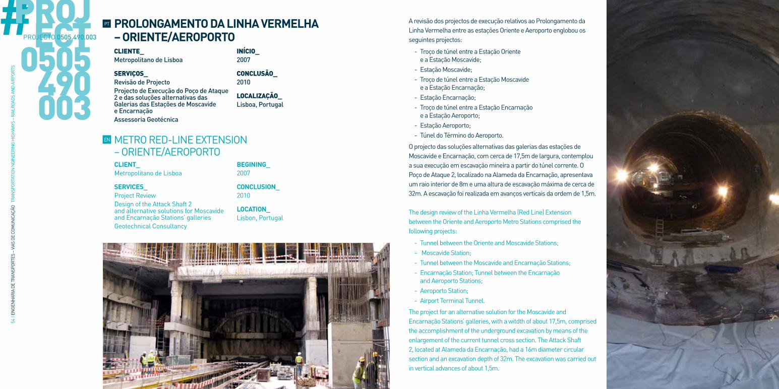
A revisão dos projectos de execução relativos ao Prolongamento da Linha Vermelha entre as estações Oriente e Aeroporto englobou os seguintes projectos:
- Troço de túnel entre a Estação Oriente e a Estação Moscavide;
- Estação Moscavide; - Troço de túnel entre a Estação Moscavide e a Estação Encarnação;
- Estação Encarnação; - Troço de túnel entre a Estação Encarnação e a Estação Aeroporto;
- Estação Aeroporto; - Túnel do Término do Aeroporto.
O projecto das soluções alternativas das galerias das estações de Moscavide e Encarnação, com cerca de 17,5m de largura, contemplou a sua execução em escavação mineira a partir do túnel corrente. O Poço de Ataque 2, localizado na Alameda da Encarnação, apresentava um raio interior de 8m e uma altura de escavação máxima de cerca de 32m. A escavação foi realizada em avanços verticais da ordem de 1,5m.
The design review of the Linha Vermelha (Red Line) Extension between the Oriente and Aeroporto Metro Stations comprised the following projects:
- Tunnel between the Oriente and Moscavide Stations; - Moscavide Station; - Tunnel between the Moscavide and Encarnação Stations; - Encarnação Station; Tunnel between the Encarnação and Aeroporto Stations;
- Aeroporto Station; - Airport Terminal Tunnel.
The project for an alternative solution for the Moscavide and Encarnação Stations’ galleries, with a witdth of about 17,5m, comprised the accomplishment of the underground excavation by means of the enlargement of the current tunnel cross section. The Attack Shaft 2, located at Alameda da Encarnação, had a 16m diameter circular section and an excavation depth of 32m. The excavation was carried out in vertical advances of about 1,5m.
METRO RED-LINE EXTENSION – ORIENTE/AEROPORTO
EN
PT PROLONGAMENTO DA LINHA VERMELHA – ORIENTE/AEROPORTOCLIENTE_ Metropolitano de Lisboa
SERVIÇOS_ Revisão de ProjectoProjecto de Execução do Poço de Ataque 2 e das soluções alternativas das Galerias das Estações de Moscavide e EncarnaçãoAssessoria Geotécnica
INÍCIO_2007
CONCLUSÃO_ 2010
LOCALIZAÇÃO_ Lisboa, Portugal
PROJECT
0505490003
PROJECTO 0505.490.003

56 |
ENGE
NH
ARIA
DE
TRAN
SPOR
TES
– VI
AS D
E CO
MUN
ICAÇ
ÃO T
RAN
SPOR
TATI
ON N
GIN
EERI
NG
HIG
HW
AYS
– RA
ILRO
ADS
AND
AIRP
ORTS
#O empreendimento constitui o prolongamento da Linha 1 do Metro de Argel para Norte, atravessando o centro da cidade na zona histórica onde se situa a Casbah, desde a Praça Emir Abdelkader até à Praça dos Mártires, com um desenvolvimento total de 1698,6m.
O projecto compreende as seguintes obras: - Túnel com o desenvolvimento total de 1430m; - Estação Praça dos Mártires com 116,2m de extensão e 18m de largura;
- Estação Ali Boumendjel com 155,7m de extensão e 18,5m de largura;
- Poços PV1 (situado no extremo norte da linha) e PV2 (situado entre as duas estações) de ventilação e de ataque com secção circular;
- Poço de acesso e de ataque à estação Ali Boumendjel.
This project includes the Line 1 extension of Argel Metro Line towards North, crossing the city center at the historical area where the Cabash is located. The alignment runs from the Emir Abdelkader square to the Martyrs square, with a total length of about 1.698,6m.
The project comprises the following main works: - Tunnel with a total length of about 1.430m; - Martyrs Square Station (116,2m long and 18m wide); - Ali Boumendjel Station (155,7m long and 18,5m wide);
- Ventilation Shafts 1 (at the northern side of the metro line) and 2 (between the two stations) with circular sections;
- Access and Ventilation Shaft at the Ali Boumendjel Station.
CLIENT_Andrade Gutierrez Teixeira Duarte – GESI-TP – zagope (GMAC – Groupement Metro d’Alger Centre)
SERVICES_Final Design Geotechnical Consultancy
BEGINING_2009
CONCLUSION_Ongoing
LOCATION_ Argel, Argélia
ALGIERS METRO LINE 1 – EXTENSION 2EN
PT METRO DE ARGEL LINHA 1 – EXTENSÃO 2 CLIENTE_ Andrade Gutierrez Teixeira Duarte – GESI-TP – Zagope (GMAC – Groupement Metro d’Alger Centre)
SERVIÇOS_ Projecto de ExecuçãoAssessoria Geotécnica
INÍCIO_2009
CONCLUSÃO_ Em Curso
LOCALIZAÇÃO_ Argel, Argélia
PROJECT
0505229021
PROJECTO 0505.229.021

58 |
ENGE
NH
ARIA
DE
TRAN
SPOR
TES
– VI
AS D
E CO
MUN
ICAÇ
ÃO T
RAN
SPOR
TATI
ON N
GIN
EERI
NG
HIG
HW
AYS
– RA
ILRO
ADS
AND
AIRP
ORTS
#
As estações 24 de Agosto, Heroísmo e S. Bento inserem-se no Metro Ligeiro do Porto. A estação 24 de Agosto foi construída pelo método “cut-and-cover” com uma área de 2000m2 e altura máxima de escavação de 23m realizada em aterros, aluviões e na formação dos “Granitos do Porto”. O sistema de entivação consistiu de paredes moldadas e paredes tipo Berlim definitivo com 0,8m de espessura; 3 níveis de escoras metálicas pré-esforçadas e 2 níveis de ancoragens. A estação Heroísmo englobou um poço de ataque e diversos túneis em escavação subterrânea constituindo o corpo principal da estação, os acessos e as galerias de ventilação. O poço apresentava uma área de 1000m2, uma altura máxima de escavação de 27m, tendo sido construído pelo método “cut-and-cover” através de um sistema de entivação misto constituído por uma cortina de estacas ancorada e revestimentos de betão projectado pregado. O corpo principal em escavação mineira tinha uma secção de escavação de 181m2 e um comprimento de 70m. A estação de S. Bento foi construída pelo método “cut-and-cover”, num recinto com 3330m2 e uma altura máxima de escavação de 21m em aterros, aluviões e na formação dos “Granitos do Porto”. O sistema de entivação misto era constituído por cortina de estacas ancoradas e revestimentos de betão projectado pregado.
The 24 de Agosto, Heroísmo and S. Bento Stations are included in the Porto’s Metro Line. The 24 de Agosto Station was built using the cut-and-cover method, with a total area of 2000m2
and an excavation maximum height of 23m executed in landfills, sediments and in the formation of “Oporto’s Granites”. The retaining structure adopted consisted of diaphragm walls and Berlin type walls supported by several levels of prestressed struts and anchors. The Heroísmo Station included a cut-and-cover shaft and several underground galleries, forming the main body of the station, the accesses and the ventilation galleries. The shaft had a 1000m2 area and an excavation maximum height of 27m, and was built using the cut-and-cover method and a retaining structure consisting of reinforced concrete anchored piles and nailed reinforced shotcrete lining walls. The main gallery had an excavation section of about 181m2 and a total length of 70m. S. Bento Station was built using the cut-and-cover method, in a 3330m2 area, and had an excavation maximum height of 21m in landfills, sediments and in the formation of “Oporto’s Granites”. The adopted retaining structures were comprised of anchored pile walls and nailed reinforced shotcrete lining walls.
CLIENT_Transmetro
SERVICES_Final Design Geotechnical Consultancy
BEGINING_2000
CONCLUSION_2005
LOCATION_ Porto, Portugal
PORTO LIGHT RAIL SYSTEM 24 AGOSTO, HEROÍSMO AND S. BENTO STATIONS
EN
PT METRO LIGEIRO DO PORTO ESTAÇÕES DE 24 DE AGOSTO, HEROÍSMO E S. BENTOCLIENTE_ Transmetro
SERVIÇOS_ Projecto de ExecuçãoAssessoria Geotécnica
INÍCIO_2000
CONCLUSÃO_ 2005
LOCALIZAÇÃO_ Porto, Portugal
PROJECT
0505380001
PROJECTO 0505.380.001

AEROPORTOSAIRPORTS
PT EN

62 |
ENGE
NH
ARIA
DE
TRAN
SPOR
TES
– VI
AS D
E CO
MUN
ICAÇ
ÃO T
RAN
SPOR
TATI
ON N
GIN
EERI
NG
HIG
HW
AYS
– RA
ILRO
ADS
AND
AIRP
ORTS
#
CLIENT_ANA – Aeroportos de Portugal S.A.Direcção de Infraestruturas Aeronáuticas (DIA)
SERVICES_Final Design(Comprising the Runway and Reestablishments scoping the Drainage, Paving, Horizontal and Vertical Marking and Enclosure’ Specialties)
BEGINING_1999
CONCLUSION_2003
LOCATION_ Pico Island, Azores, Portugal
PICO’S AIRPORT. RUNWAY 10-28 EXTENSION PROJECT, AzORES
EN
PT AEROPORTO DO PICO. ELABORAÇÃO DO PROJECTO DE AMPLIAÇÃO DA PISTA 10-28, AÇORES CLIENTE_ ANA – Aeroportos de Portugal S.A.Direcção de Infraestruturas Aeronáuticas (DIA)
SERVIÇOS_ Projecto de Execução (Envolvendo Pista e Restabelecimentos nas especialidades de Drenagem, Pavimentação, Sinalização Horizontal e Vertical, Sinalização Luminosa e Vedação)
INÍCIO_1999
CONCLUSÃO_ 2003
LOCALIZAÇÃO_ Ilha do Pico, Açores, Portugal
PROJECT
0101342001
PROJECTO 0101.342.001
Ampliação e alargamento da Pista 10-28 e restabelecimento de estradas interferidas para permitir a operação de aeronaves do tipo Boeing B737-300 e Airbus A319 e A320 e tendo em vista a sua reclassificação para a classe 3D. O projecto envolveu o aumento do comprimento da pista de 1.520m para 1.760m e o alargamento da Plataforma de 30 para 45m pavimentados, tendo 30m de faixa de rodagem a duas bermas de 7,5m de largura e ainda o alargamento da faixa de protecção “STRIP” para um total de 150m (75m para cada lado do eixo).
Extension of the 10-28 Runway and reestablishment of roads to allow the operation of airplanes like the Boeing B737-300 and Airbus A319 or A320, in order to obtain a 3D Class Airport. The project involved the runway extension from 1.520m to 1.760m and the platform enlargement from 30 to 45 paved meters, for a 30 m runway width and two shoulders, 7,5m wide. The project included the enlargement of the runway strip protection to a total of 150m (75m for each side of the axe).

64 |
ENGE
NH
ARIA
DE
TRAN
SPOR
TES
– VI
AS D
E CO
MUN
ICAÇ
ÃO T
RAN
SPOR
TATI
ON N
GIN
EERI
NG
HIG
HW
AYS
– RA
ILRO
ADS
AND
AIRP
ORTS
#O Projecto apresentado refere-se à reabilitação das áreas de movimento do aeródromo do Uíge tendo em vista a melhoria das condições de segurança das operações de transporte aéreo, nomeadamente para as novas aeronaves a operar em Angola tais como os Boeings 727-200 e 737-700 W. O Aeródromo do Uíge, apresenta uma pista com 2000m de comprimento e 30m de largura, dois caminhos de circulação e uma placa de estacionamento de aeronaves. A pista, os caminhos de circulação e a placa apresentam um pavimento revestido a asfalto muito degradado, com fendas, cavados de rodeiras e depressões várias, não dispondo de bermas, de faixa de segurança desmatada (“STRIP”) e nem de áreas de segurança de fim de pista “RESA”. A reabilitação inclui a beneficiação do pavimento existente, o aumento do comprimento da pista para 2.300m e o aumento da largura da plataforma para 45m, a introdução de bermas pavimentadas, a desmatação e terraplenagem do “STRIP”, a construção de áreas de segurança de fim de pista (“RESA”), ficando o aeroporto com a classificação 4C. O projecto inclui a sinalização aeroportuária diurna da pista, caminhos de circulação e placa de estacionamento bem como a sinalização luminosa adequada a aproximações com instrumentos de não precisão.
This project refers to Uige’s Airport maneuvering areas rehabilitation, foreseeing the improvement of the air transport safety conditions, namely to the new airplanes to operate in Angola, such as Boeings 727-200 and 737-700 W. Uige’s Airport has a runway 2.000m long and 30m wide, two taxi-ways and an airplane parking platform. The runway, the taxi-ways and the parking platform present a very deteriorated asphalt pavement, with cracks, wheel paths erosion and several depressions. The Aerodrome does not have any shoulders or any ground cleared runway strip protections (STRIP) nor any Runway End Safety Areas (RESA). The rehabilitation includes the existent pavement improvement, the extension of the runway to 2300m through earthworks, the increase of the platform width to 45m, the introduction of paved shoulders, the ground clearance and earthworks of the runway strip protection, and the construction of RESA’s areas, in order to obtain a 4C classification. The indicators and signaling devices, markings of the runway, taxi-ways and parking platform, as well as the adequate lighting signs to non-precision instrument approaches were also included in this project.
CLIENT_Tecnovia Angola - ENANA
SERVICES_Final Design
BEGINING_2008
CONCLUSION_Ongoing
LOCATION_ Uíge, Angola
REHABILITATION OF UIGE’S AIRPORT, ANGOLAEN
PT REABILITAÇÃO DO AEROPORTO DE UIGE, ANGOLA CLIENTE_ Tecnovia Angola - ENANA
SERVIÇOS_ Projecto de Execução
INÍCIO_2008
CONCLUSÃO_ Em Curso
LOCALIZAÇÃO_ Uíge, Angola
PROJECT
0106609001
PROJECTO 0106.609.001

www.cenor.pt
Empresas Grupo CENOR_ CENOR Group companies_ECGPLAN, Engenharia, Gestão e Planeamento, Lda. [Madeira, Portugal_ Madeira, Portugal_]CENOR, Açores, Lda. [Açores, Portugal_ Azores, Portugal_]CENOR, Consultores Angola, Lda. [Luanda, Angola_ Luanda, Angola_]CENOR, Argélia [Argel, Argélia_ Alger, Algeria_]CENOR, Colômbia [Bogotá, Colômbia_ Bogotá, Colômbia_]CENOR, Iraque [Bagdá, Iraque_ Baghdad, Iraq_]
Empresas Participadas_ Subsidiary Companies_NVIST [Lisboa, Portugal_ Lisbon, Portugal_]CENORVIA MZ [Maputo, Moçambique_ Maputo, Mozambique_]SCCONSULT [Belo Horizonte, Brasil_ Belo Horizonte, Brazil_]DALAN [Díli, Timor Leste_ Díli, East Timor_]

NOVEMBRO 2013
CENOR Consultores, S.A.Rua das Vigias, 2 . Piso 1 Parque das Nações 1990-506 Lisboa LISBOA . PORTUGAL
T. +351 218 437 300 F. +351 218 437 301 E. [email protected]
www.cenor.pt
CO-FINANCIAMENTO