a new model for broadband waveguide to microstrip ... technical memorandum .88905 .. * a new model...
TRANSCRIPT

NASA Technical Memorandum .88905 . . *
A New Model for Broadband Waveguide to Microstrip Transition Design
George E. Ponchak and Alan N. Downey Lewis Research Center Cleveland, Ohio
(NASA-TM-88905) h A V E G I J l D k TO H 9 I C L L S Z B I E T I i A L S I I I C L C E S I G N
( N A S A ) 18 F CSCL 17B
A NE& HODEL FCl i BRCADBAMD Nd7-16958
December 1986
b
https://ntrs.nasa.gov/search.jsp?R=19870007525 2018-05-11T05:23:39+00:00Z

A NEW MODEL FOR BROADBAND WAVEGUIDE TO
M I C R O S T R I P T R A N S I l I O N DESIGN
George E . Ponchak and A lan N. Downey N a t i o n a l Aeronaut ics and Space A d m i n i s t r a t i o n
Lewis Research Center Cleveland, Ohio 44135
SUMMARY
A new model i s p resented which p e r m i t s t h e p r e d i c t i o n o f t h e resonant f requenc ies c rea ted by a n t i p o d a l f i n l i n e waveguide t o m i c r o s t r i p t r a n s i t i o n s . The t r a n s i t i o n i s modeled as a tapered t r a n s m i s s i o n l i n e i n s e r i e s w i t h an
UJ i n f i n i t e s e t o f coupled resonant c i r c u i t s . The resonant c i r c u i t s a r e modeled M cn as s imp le microwave resonant c a v i t i e s o f wh ich t h e resonant f requenc ies a r e CJ e a s i l y de termined. The model i s developed and t h e resonant f requenc ies d e t e r - w mined f o r seve ra l d i f f e r e n t t r a n s i t i o n s . Exper imenta l r e s u l t s a r e g i v e n t o I
c o n f i r m t h e models.
I N T R O D U C T I O N
The use o f f requenc ies above 18 GHz f o r government and commercial communi c a t i o n s a p p l i c a t i o n s i s expected t o i n c r e a s e r a p i d l y i n t h e nex t few years . Low c o s t systems i n t h i s f requency range w i l l u t i l i z e s o l i d s t a t e dev ices i n t h e fo rm o f m o n o l i t h i c microwave I n t e g r a t e d c i r c u i t s (MMlC's). 1-he c u r r e n t t r e n d i n s o l i d s t a t e microwave i n t e g r a t e d c i r c u i t s i s t o use m i c r o s t r i p t r a n s - m i s s i o n l i n e s f o r d e v i c e i n t e r c o n n e c t i o n s . However, a l l t e s t equipment i n t h e m i l l i m e t e r wave f requency range u t i l i z e s r e c t a n g u l a r waveguide. I n a d d i t i o n , r e c t a n g u l a r waveguide w i l l be used i n phased a r r a y antennas and o t h e r systems i n wh ich t h e s i g n a l must t r a v e l an a p p r e c i a b l e d i s t a n c e i n a medium o t h e r than f r e e space. Therefore, a low cos t , e a s l l y f a b r i c a t e d waveguide t o m i c r o s t r i p t r a n s i t i o n wh ich has low l o s s and broad bandwidth w i l l be e s s e n t i a l i n t h e t e s t and imp lemen ta t i on o f any system u t i l i z i n g M M I C ' s .
The a n t i p o d a l f i n l i n e waveguide t o m i c r o s t r i p t r a n s i t i o n was f i r s t demon- s t r a t e d by J.H.C. van Heuven ( r e f . 1 ) . Th i s and t h e many d e r i v a t i o n s o f i t seen i n t h e l i t e r a t u r e ( r e f s . 2 t o 4 ) ( f i g . 1 ) a r e a t t r a c t i v e f r o m t h e system i n t e g r a t i o n p o i n t o f v iew s ince they a r e i n l i n e w i t h t h e waveguide and can be e a s i l y manufactured on inexpens ive , s o f t s u b s t r a t e s u s i n g s tandard p r i n t e d c i r - c u i t board techn iques . The problem w i t h u s i n g t h e a n t i p o d a l f i n l i n e t r a n s i - t i o n has been o b t a i n i n g broadband response f rom a s imp le s e t o f des ign r u l e s . l h e d e s i g n i s compl ica ted s ince the t r a n s i t i o n c rea tes a s e t o f resonant modes wh lch l i m i t t h e u s e f u l bandwidth of t h e t r a n s i t i o n . A t y p i c a l S21 measure- ment o f a t r a n s i t i o n demonst ra t ing t h i s phenomenon i s shown i n f i g u r e 2.
*
The resonances a r e a major problem i n t r a n s i t i o n des ign and may even exc lude t h i s t y p e of t r a n s i t i o n f r o m b e i n g used under c e r t a i n c i rcumstances . I n a s tandard c o n f i g u r a t i o n , t h e component under t e s t i s i n s e r t e d between two t r a n s i t i o n s w i t h a s h o r t s e c t i o n of m i c r o s t r i p s e p a r a t i n g t h e d e v i c e f rom t h e t r a n s i t i o n t o m in im ize l o s s . The resonances o f t h e t r a n s i t i o n may t h e r e f o r e coup le t o t h e d e v i c e under t e s t i f t h e bandwidth o f t h e d e v i c e ove r laps t h e
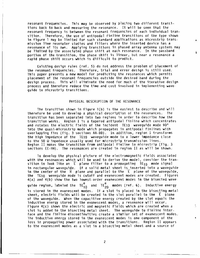
resonant f requenc ies . t i o n s back t o back and measuring t h e resonance. I t w i l l be seen t h a t t h e resonant frequency i s between t h e resonant f requenc ies o f each i n d i v i d u a l t r a n - s i t i o n . Therefore, t h e use o f a n t i p o d a l f i n l i n e t r a n s i t i o n s o f t h e t y p e shown i n f i g u r e 1 may be l i m i t e d f o r such s tandard a p p l i c a t i o n s as m i c r o s t r i p t r a n s - * m i s s i o n l i n e resonator s t u d i e s and f i l t e r s where t h e i n s e r t e d d e v i c e has a resonance o f I t s own. App ly ing t r a n s i t i o n s i n phased a r r a y antenna systems may be l i m i t e d by t h e assoc ia ted phase s h i f t a t each resonance. I n t h e passband p o r t i o n o f t he t r a n s i t i o n , t h e phase s h i f t i s l i n e a r , b u t near a resonance a r a p i d phase s h i f t occurs which i s d i f f i c u l t t o p r e d i c t .
Th is may be observed by p l a c i n g two d i f f e r e n t t r a n s i -
E x i s t i n g des ign r u l e s ( r e f . 5 ) do n o t address t h e problem o f placement o f t h e resonant f requenc ies . There fore , t r i a l and e r r o r des ign i s s t i l l used. Th is paper presents a new model f o r p r e d i c t i n g t h e resonances which p e r m i t s placement o f the resonant f requenc ies o u t s i d e t h e d e s i r e d band d u r i n g t h e des ign process. Th is w i l l e l i m i n a t e t h e need f o r much o f t h e i t e r a t i v e des ign process and t h e r e f o r e reduce t h e t i m e and c o s t i n v o l v e d i n imp lement ing wave- gu ide t o m i c r o s t r i p t r a n s i t i o n s .
PHYSICAL D E S C R I P T I O N OF THE RESONANCE
The t r a n s i t i o n shown i n f i g u r e l ( b ) i s t h e e a s i e s t t o d e s c r i b e and w i l l t h e r e f o r e be used t o develop a p h y s i c a l d e s c r i p t i o n o f t h e resonances. The t r a n s i t i o n has been separated i n t o two reg ions i n o rde r t o d e s c r i b e how the t r a n s i t i o n works. RegSon I i s a tapered a n t i p o d a l f i n l i n e which concen t ra tes and r o t a t e s the e l e c t r i c f i e l d s o f t h e i n c i d e n t T E l O waveguide mode 90" i n t o t h e q u a s i - m i c r o s t r i p mode wh ich propagates i n a n t i p o d a l f i n l i n e s w i t h o v e r l a p p i n g f i n s ( f i g . 3 s e c t i o n s A A - D D ) . I n a d d i t i o n , r e g i o n I t rans fo rms t h e h i g h impedance o f t h e T E l O waveguide mode t o a lower impedance c l o s e t o t h e 50 R impedance u s u a l l y used f o r m i c r o s t r i p t r a n s m i s s i o n l i n e s . Region I 1 makes t h e t r a n s i t i o n f rom a n t i p o d a l f i n l i n e t o m i c r o s t r i p ( f i g . 3 s e c t i o n s EE-HH). The resonances a r e c r e a t e d i n r e g i o n I 1 as w i l l be shown.
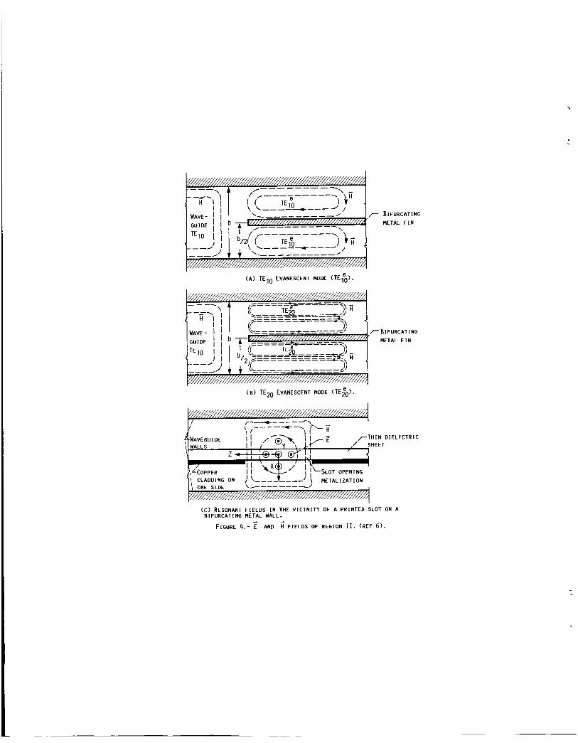
To develop t h e p h y s i c a l p i c t u r e o f t h e e lec t romagne t i c f i e l d s assoc ia ted w i t h t h e resonances which w i l l be used t o d e r i v e t h e model, cons ide r t h e t r a n - s i t i o n t o look l i k e an r p l a n e f i l t e r t o a p ropaga t ing T E l O mode s i g n a l i n r e c t a n g u l a r waveguide. I f a s o l i d me ta l sheet i s - i n s e r t e d i n t o a waveguide i n t h e c e n t e r o f t h e fi p lane and p a r a l l e l t o t h e t p l a n e o f t h e waveguide, t h e T E l O waveguide mode i s c u t o f f and evanescent modes a r e c rea ted . F igu res 4 ( a ) and 4 ( b ) show t h e two lowes t -o rde r evanescent modes i n t h e b i s e c t e d wave-
gu ide reg ion , l abe led t h e TEIO and TEZ0 modes ( r e f . 6 ) . I n d u c t i v e energy
i s s t o r e d i n the evanescent modes. I f a s l o t i s p laced i n t h e b i s e c t i n g - meta l sheet , e l e c t r i c f i e l d s w i l l be c rea ted i n t h e s l o t p a r a l l e l t o t h e E p lane o f t h e waveguide. When t h e c a p a c i t i v e energy c r e a t e d by t h e s l o t equa ls t h e i n d u c t i v e energy s t o r e d i n t h e evanescent modes, a resonance w i l l occur . F i g u r e 4 ( c ) shows t h e e l e c t r i c and magnet ic f i e l d s wh ich a r e c r e a t e d when a s l o t i s added t o t h e b i s e c t i n g meta l sheet . The waveguide t o f i n l i n e i n t e r - f ace and t h e f i n l i n e d i s c o n t i n u i t i e s c r e a t e a s i m i l a r s e t o f evanescent modes. l h e i n d u c t i v e energy s to red i n t h e evanescent modes i s one component o f t h e l o s s I n p ropagat ing power assoc ia ted w i t h t h e t r a n s i t i o n s . Region I 1 appears t o t h e evanescent modes as a s l o t i n a b i s e c t i n g meta l sheet and a source o f
e e
L

c a p a c i t i v e energy. l h e r e f o r e , r e g i o n I 1 i s t h e source o f t h e resonances which p laque t h e t r a n s i t i o n .
MODEL DEVELOPMENT
A n a l y t i c a l methods t o o b t a i n t h e resonant f requenc ies u s i n g t h e above d e s c r i p t i o n would be d i f f i c u l t t o implement f o r a compl ica ted s t r u c t u r e such as t h e t r a n s i t i o n . There fore , a model based on t h e e lec t romagne t i c f i e l d diagrams d e r i v e d i n f i g u r e 4 and exper imen ta l l y d e r i v e d parameters i s d e v e l - oped. I n t h e tapered a n t i p o d a l f i n l i n e r e g i o n , a quas i T E i O mode propa- ga tes . I n r e g i o n I 1 and t h e m i c r o s t r i p , a quas i TEM mode propagates. The evanescent modes decay r a p i d l y and t h e r e f o r e do n o t propagate. There fore , t h e quas i TEM and t h e T E l O modes must propagate i ndependen t l y o f t h e evanes- cen t modes f o r a l l f r equenc ies except those near t h e resonant f requency, f r , o f r e g i o n 11. Near f r , t h e propagat ing wave couples energy t o t h e resona to r i n t h e same manner as any t ransmiss ion l i n e would coup le energy t o a r e a c t i v e resonant c a v i t y p laced w i t h i n t h e e lec t romagnet ic f i e l d s o f t h e p ropaga t ing wave. There fore , i f t h e resonant frequency cou ld be modeled by a c a v i t y reso - n a t o r o f a fo rm r e l a t e d t o t h e shape o f r e g i o n 11, an e q u i v a l e n t c i r c u i t model cou ld be used such as i n f i g u r e 5 . Each RLC c i r c u i t rep resen ts a mode o f an e q u i v a l e n t resonant c a v i t y . Assuming the Q o f each resona to r i s l a r g e and t h e resonant modes a r e n o t c l o s e together , t hen each resonant mode can be con- s ide red t o be decoupled and placement o f t h e resonant f requenc ies may be made by a s imp le a l t e r a t i o n t o r e g i o n 11.
The c h o i c e o f t h e resonant c a v i t y t o model r e g i o n I 1 must be dependant on t h e e l e c t r i c and magnet ic f i e l d s o f reg ion 11. The p r i m a r y mode i n r e g i o n I 1 i s a LSE mode. The e l e c t r i c f i e l d s a re concen t ra ted i n t h e s l o t , o r r e g i o n 11, i n t h e p lane o f t h e waveguide. Ou ts ide o f t h e c e n t e r o f t h e Ti p lane, t h e e l e c t r i c f i e l d s decay t o zero a t t h e waveguide w a l l s , X = ?b/2 o f f i g u r e 4 ( d ) . The magnet ic f i e l d l i n e s must e n c i r c l e t h e e l e c t r i c f i e l d l i n e s and a r e c o n s t r a i n e d by t h e waveguide w a l l s and t h e meta l sheet wh ich forms r e g i o n 11.
.
The shape o f r e g i o n I 1 and t h e LSE mode f i e l d s i n t h e r e g i o n suggest a c y l i n d r j c a l waveguide c a v i t y w i t h a b i s e c t i n g meta l sheet i n t h e E p lane . Resonant modes o f t h e f o r m T E n l l , n ?.l, have f i e l d s which a r e s i m i l a r t o those o f r e g i o n 11. I n a d d i t i o n , u n l i k e an e l i p t i c a l waveguide resonant c a v i t y which would more c l o s e l y d e s c r i b e reg ion 11, t h e resonant f requenc ies o f c y l i n - d r i c a l c a v i t i e s a r e e a s i l y ob ta ined. There fore , a c y l i n d r i c a l c a v i t y f i l l e d w i t h a m a t e r i a l o f some & e f f hav ing a r a d i u s o f x/2 and a l e n g t h b i s proposed t o model r e g i o n I 1 (see f i g . 6 ( a ) ) .
The resonant f requenc ies a r e dependent on t h e a v a i l a b l e c a v i t y volume so an e f f e c t i v e p e r m i t t i v i t y i s in t roduced t o make t h e resonant f requency o f t h e c y l i n d r i c a l c a v i t y c o i n c i d e w i t h t h e exper imenta l va lues . The proposed model i s s imp le and i t s use fu lness i s dependant on whether o r n o t a s i n g l e va lue o f C e f f can be found such t h a t va r ious resonant f requenc ies can be a c c u r a t e l y p r e d i c t e d . I t w i l l be shown t h a t t h l s i s t he case f o r many t r a n s i t i o n s t h a t have been s t u d i e d e x p e r i m e n t a l l y . I t was found t h a t teff i s dependant on t h e l e n g t h parameter x b u t was e s s e n t i a l l y independent o f f requency . Thus, f o r a g i v e n t r a n s i t i o n , t h e va r ious resonant f requenc ies can be p r e d i c t e d accu- r a t e l y f r o m t h e model.
3

The resonant f requenc ies a r e d e r i v e d by s e t t i n g t h e p ropaga t ion cons tan t f o r c y l i n d r i c a l waveguide equal t o n /b where b i s t h e l e n g t h o f t h e wave- gu ide c a v i t y . The r e s u l t i n g equa t ion f o r t h e resonant f requenc ies i s :
= - C [(!LC2+ (;)j ll2
fnll 2 T T m
where
x/2 i s t h e rad ius o f t h e c y l i n d e r Pn1 a r e r o o t s o f t h e equa t ion d J n ( k c r ) / d r = 0,
t e f f i s some frequency dependant e f f e c t i v e d i e l e c t r i c cons tan t ( r e f . 7 ) . The s o l u t i o n f o r E e f f would p e r m i t t h e d e t e r m i n a t i o n o f t h e resonant f requency. U n f o r t u n a t e l y , a t h e o r e t i c a l de ie f -mina t ion o f Eef f i s d i f f i c u l t . There fore , an e x p e r i m e n t a l l y d e r i v e d Eeff w i l l be found.
r = x/2, and Kc = c u t o f f wave number o f t h e wave gu ide
EXPERIMENTAL RESULTS
T r a n s i t i o n s were f a b r i c a t e d f o r v a r i o u s l e n g t h s o f r e g i o n 11, x . I n genera l , t h e t o t a l l e n g t h o f t h e t r a n s i t i o n , L = l e n g t h o f r e g i o n I p l u s x , was kep t cons tan t . The t r a n s i t i o n l e n g t h , L, was equal t o hg ( f = 32 GHz) o f t h e T E l o r e c t a n g u l a r waveguide mode f o r Ka band t r a n s i t i o n s . The t r a n - s i t i o n s were f a b r i c a t e d on 10 m i l , c r = 2 - 7 2 Duro id and 10 m i l , t r = 2.17 Cu Clad subs t ra tes . A l l t e s t i n g was done f o r two back - to -back t r a n s i t i o n s i n t e r c o n n e c t e d by 3.80 cm o f 50 R m i c r o s t r i p . The t r a n s i t i o n s were mounted f o r t e s t i n g i n a t e s t f i x t u r e shown i n f i g u r e 7 which when clamped t o g e t h e r s u p p l i e d s u f f i c i e n t c o n t a c t between t h e meta l f i n l i n e s and t h e waveguide w a l l s . Measurements were taken on a m o d i f i e d H e w l e t t Packard 8409 au tomat i c network ana lyze r .
The measured resonant f requenc ies , f r , a r e p l o t t e d versus x f o r two d i f f e r e n t shaped r e g i o n I 1 i n f i g u r e 8. I n a d d i t i o n , t r a n s i t i o n s were made w i t h s t r a i g h t f i n l i n e tape rs and/or t r i a n g u l a r shaped r e g i o n 11. I t was found t h a t t h e f i n l i n e tape r made o n l y smal l d i f f e r e n c e s i n t h e resonant f requency . A lso, as can be seen i n f i g u r e 8, t h e exac t c u r v a t u r e o f r e g i o n I 1 d i d n o t s i g - n i f i c a n t l y a l t e r t h e resonant f requency . The domina t ing d e t e r m i n a t i o n o f f r i s t h e l e n g t h x. Th is p e r m i t s t h e developed curves t o be used f o r a broad range o f a n t i p o d a l f i n l i n e s w i t h o u t an exac t knowledge of t h e c u r v a t u r e o f r e g i o n 11. teff as a f u n c t i o n of x and f requency were ob ta ined and a r e p l o t t e d i n f i g u r e 9.
Using equa t ion ( 1 ) and t h e r e s u l t s f rom f i g u r e 8 va lues o f
MODEL D E R I V A T I O N FOR OTHER TRANSITIONS
The curves drawn i n f i g u r e 8 may be ob ta ined u s i n g o n l y a few w e l l p laced da ta p o i n t s . This a l l o w s a q u i c k d e t e r m i n d t i o n o f t h e resonant f requency f o r a r e g i o n I 1 o f any l e n g t h , X . This approach was f o l l o w e d f o r a d e t e r m i n a t i o n o f t h e resonant f requency f o r K band t r a n s i t i o n s ( f i g . 1 0 ) . A l l d imensions were d i r e c t l y scaled f r o m Ka band t r a n s i t i o n s .
4

The van Heuven t r a n s i t i o n may be desc r ibed by t h e e q u i v a l e n t c i r c u i t model i n f i g u r e 5. A major comp l i ca t i on though i s t h a t t h e RLC c i r c u i t s must d e s c r i b e two resonant c a v i t i e s and a l l o f t h e i r resonant modes. I n a d d i t i o n , t h e resonant modes o f t h e two c a v i t i e s a r e now c l o s e l y coupled. There fo re t h e p o s i t i o n i n g o f t h e resonant f requencies by an independent change o f e i t h e r x l , o r x2 becomes imposs ib le w i t h o u t an a c c u r a t e model o f t h e c o u p l i n g coe f - f i c i e n t s . E m p i r i c a l l y d e r i v e d curves such as those i n f i g u r e s 8 and 10 may be developed. When t h i s was done, i t was n o t i c e d t h a t t h e bandwidth o f t h e t r a n - s i t i o n was l e s s than t h a t f o r t h e t r a n s i t i o n i n f i g u r e s l ( b ) and ( c ) .
T r a n s i t i o n s w i t h a s e m i c i r c u l a r metal f i n added t o r e g i o n I 1 on t h e m ic ro - s t r i p s i d e o f t h e t r a n s i t i o n ( f i g . l ( c ) ) may be modeled as a s l o t l i n e resona- t o r . An advantage o f t h i s t y p e o f t r a n s l t i o n i s t h e accuracy t o wh ich t h e resonant f requenc ies may be p r e d i c t e d . The gu ide wavelength o f a s t r a i g h t s l o t l i n e may be accu- r a t e l y determined by such methods as the s p e c t r a l domain method ( r e f . 8 ) and Cohn's method ( r e f . 9 ) . I t has been shown by Kawano ( r e f . 10) t h a t t h e curva- t u r e o f a s l o t l i n e does n o t a l t e r the resonant f requenc ies o f a s l o t l i n e r e s o n a t o r . Simons ( r e f . 11) has shown t h a t t h e placement o f a s l o t l i n e i n r e c t a n g u l a r waveguide has n e g l i g i b l e e f f e c t on hg/ho. There fore , t h e resonant f requenc ies may be modeled by a s t r a i g h t s l o t l i n e resona to r o f l e n g t h and w i d t h equal t o those o f t h e s l o t i n reg ion I 1 l o c a t e d i n t h e c e n t e r o f a rec - t a n g u l a r waveguide. The gu ide wavelength o f s l o t s f a b r i c a t e d on c r = 2.22, 10 m i l s u b s t r a t e s has been determined by Simons ( r e f . 11) u s i n g Cohn's tech - n ique f o r va r ious s l o t w i d t h s and f requenc ies I n Ka band T E l O mode r e c t a n - g u l a r waveguide. Th is da ta was used t o de te rm ine t h e resonant f requenc ies ( s l o t l e n g t h L = nXg/2). The resonant f requenc ies a r e p l o t t e d i n f i g u r e 11. T r a n s i t i o n s were made w i t h s l o t w id ths o f 0.0254 cm and t e s t e d . There was good agreement t o t h e p r e d i c t e d values. Kawano ( r e f . 10) has shown t h a t t h e resonant f requency inc reases as t h e s l o t w i d t h i nc reases . There fore , t h e r e a r e t w o parameters which may be v a r i e d t o change f r .
The e l e c t r i c and magnet ic f i e l d s a r e shown i n f i g u r e 6 ( b ) .
CONCLUSIONS
A p h y s i c a l d e s c r i p t i o n o f t h e resonant f requency modes o f a n t i p o d a l f i n - l i n e waveguide t o m i c r o s t r i p t r a n s i t i o n s has been presented . A new model has been developed which p e r m i t s t h e p r e d i c t i o n o f t h e resonant f requenc ies . Measurements have been per formed t o v e r i f y t h e models. The models a r e s c a l a b l e t o o t h e r f requency bands. The model f o r t h e t r a n s i t i o n shown i n f i g u r e l ( c ) i s e s p e c i a l l y a t t r a c t i v e s ince t h e o r e t i c a l va lues f o r a l l t h e necessary param- e t e r s a r e a v a i l a b l e i n t h e l i t e r a t u r e . The use o f these models should reduce t h e t i m e and c o s t i n v o l v e d i n des ign ing waveguide t o m i c r o s t r i p t r a n s i t i o n s o f a d e s i r e d c h a r a c t e r i s t i c .
ACKNOWLEDGEMENTS
The au tho rs a r e g r a t e f u l t o Dr. R.N. Simons and O r . R.E. C o l l i n f o r r e v i e w i n g t h i s paper and o f f e r i n g many h e l p f u l suggest ions . A lso, Bruce V i e r g u t z , Char les H u l b e r t and Dennis Young f o r h e l p i n f a b r i c a t i n g and t e s t i n g o f t h e t r a n s i t i o n s .
5

REFERENCES
1. van Heuven, J.H.C.: A New I n t e g r a t e d Wavegu ide -M ic ros t r i p T r a n s i t i o n . I E E E Trans. Microwave Theory Tech., v o l . 24, no. 3, Mar. 1976, pp . 144-147.
2. Dydyk, M . ; and Moore, B. D . : S h i e l d e d M i c r o s t r i p A ids V-Band Rece iver Des igns . Microwaves, v o l . 21, no. 3, Mar. 1982, pp. 77-82.
3. Begemann, G . : An X-Band Balanced F i n - L i n e M i x e r . I E E E Trans . Microwave Theory Tech., v o l . 26, no. 12, Dec. 1978, pp. 1007-1011.
4. Rubin 0.; and Saul , D.L.: M i l l i m e t e r Wave M I C Bandpass F i l t e r s and M u l t i p l e x e r s . 1978 I E E E - M T T - S I n t e r n a t i o n a l Microwave Symposium D i g e s t , I E E E , 1978, pp. 208-210.
5 . Lavedan, L.J.: Design o f W a v e g u l d e - t o - M i c r o s t r i p T r a n s i t i o n s S p e c i a l l y S u i t e d t o M i l l i m e t r e - W a v e A p p l i c a t i o n s . E l e c t r o n . L e t t . , v o l . 13, no. 20, Sept . 29, 1977, pp. 604-605,.
6. K o n i s h i , Y . ; e t a l . : New Microwave Components w i t h Mounted P lanar C i r c u i t I n Waveguide. NHK L a b o r a t o r i e s Note, 163, Japan B r a o d c a s t i n g Corp., Tokyo, Mar. 1973.
7. C o l l i n , R . E . : Foundat ions f o r Microwave Eng ineer ing , M c G r a w - H i l l , 1966.
8. Schmidt, L.P.; and I t o h , T . : S p e c t r a l Domain A n a l y s i s o f Dominant and H i g h e r Order Modes I n F i n - L i n e s . I E E E Trans . Microwave Theory Tech., v o l . 28, no. 9, Sept. 1980, pp. 981-985.
9 . Cohn, S.B.: S l o t L i n e on a D i e l e c t r i c S u b s t r a t e . I E E E Trans. Microwave Theory Tech., v o l . 17, no. 10, O c t . 1969, pp. 768-778.
10. Kawano, K . ; and Tominuro, H . : S l o t R ing Resonator and D i s p e r s i o n Measurement on S l o t L i n e s . E l e c t r o n . L e t t . , v o l . 17, no. 24, Nov. 26, 1981, pp. 916-917.
11. Slmons, R . N . : A n a l y s i s o f M i l l ime t re -Wave I n t e g r a t e d F i n - L i n e . I E E Proc., Par t H: Microwaves, Opt. Antennas, v o l . 130, no. 2, Mar. 1983, pp . 166-169.
,

/ - / I
,I I
(A) WAVEGUIDE TO MICROSTRIP TRANSITION PROPOSED BY VAN HEUVEN. (REF 1 ) .
I MI REGION I- REGION I I ~
(B) S I M P L I F I E D VAN HEUVEN TRANSIT ION.
(C) S I M P L I F I E D VAN HEUVEN TRANSITION WITH SEMICIRCULAR METAL F I N .
50 il MICROSTRIP
FIGURE 1.- TYPES OF ANTIPODAL F INL INE WAVEGUIDE TO MICRO- STRIP TRANSITIONS.

0
-10
-20
-30
400 200 0
-200 -400 -600 -800
-loo0 - 1200 -1400 -1600 -1800
c
-2000 26 000 40 000
FREQUENCY, MHz
FIGURE 2.- Sgl MEASUREMENTS OF ANTIPODAL
F I N L I N E WAVEGUIDE TO MICROSTRIP TRANSI-
T I O N .
I

€-E F-F
c-c D-D
1 111 1
6-G H-H
FIGURE 3.- ELECTRIC FIELDS AT VARIOUS CROSS SECTIONS ALONG THE TRANSITION FROM CONVENTIONAL RECTANGULAR WAVEGUIDE TO A 50 MICROSTRIP AS SHOWN IN FIGURE fB.
BIFURCATING METAL F I N
( A ) T E ~ ~ EVANESCENT MODE ( T E ~ ~ ) .
r BIFURCATING METAL F I N
(8) ~t~~ EVANESCENT MODE ( ~ ~ 2 e g ) .
r T ~ ~ ~ D I E L E C T R I C
( C ) RESONANT F I E L D S I N THE V I C I N I T Y OF A PRINTED SLOT ON A
FIGURE 4.- AND ;F IELDS OF REGION 1 1 . (REF 6). BIFURCATING METAL WALL.

f
b \
\ /-
RESONANCE FORMED DUE TO
F I N L I N E DISCONTINUITIES
AND :HEIR ASSOCIATED E AND H FIELD COMPONENTS)
t D )
FIGURE 4. CONCLUDED.
br7 50 fl HICROSTRIP
-PARASITIC RESONATOR WAVE- GUIDE
TE10 B(Z). Z c ( Z ) 2, = 50-
WAVEGUIDE - - - QUASI
TEH AN EQUIVALENT RLC C I R C U I T REPRESENTING THE
LOWEST ORDER RESONANT
FREQUENCY OF THE
PARASTIC SLOT RESONATORJ HIGHER ORDER
RESONANT MODES
FIGURE 5.- AN EQUIVALENT LUMPED ELEMENT MODEL FOR A WAVEGUIDE TO MICROSTRIP TRANSITION.

- A
L B I S E C T I N G METAL SHEEl
I
( A ) T E l l l MODE OF AN EOUIVALENT CYLINDRICAL WAVEGUIDE CAVITY, HOMO-
GENEOUSLY F I L L E D WITH SOME MATERIAL OF 'eft.
' I '\ I ii
METAL
(B) FIRST ORDER. RESONANT MODE OF AN EOUIVALENT SLOT RESONATOR.
FIGURE 6.- EOUIVALENT RESONANT C A V I T I E S FOR TRANSITIONS SHOWN I N FIGURES 1B AND 1 C .

FIGURE 7. - 26.5 - 40 GHZ WAVEGUIDE TO MICROSTRIP TRANSITION IN TEST FIXTURE.

40
38
N 36 I L 3
> U 2 34 Q w e
k 32 9 x Y E
30
28
26 0 .2 .4 .6 .8 1.0 1.2 1.4
x, CM
FIGURE 8.- RESONANT FREQUENCY AS A FUNCTION OF x FOR KA BAND TRANSITIONS.

4.2
3.8
3.4
3.0
c 6 2.6
W
2.2
1.8
1.4
a = 0.3556 cn L
\\ - b . l
1 .o 0 .2 .4 .6 .8 1.0 1.2 1.4
x. CH
FIGURE 9.- Eeff VERSUS X FOR KA BAND TRANSITIONS.
26
2 24 ;
p 22
9 5
2 W
0
U
c
: 20
18
a = 0.4318 CM = 1.0668 CH = 0.0254 CH
E r = 2.22
1 " 0 .2 .4 .6 .8 1.0
x . CH
FIGURE 10.- RESONANT FREPUENCY VERSUS x FOR K BAND TRANSITIONS.

42
N 38 x W
; z Y a
g 34 U I-
4
51 cc 30
26
LENGTH OF SLOT L. CH
FIGURE 11.- RESONANT FREQUENCY VERSUS SLOT LENGTH L.

1. Report No.
NASA TM-88905
A New Model for Broadband Waveguide t o Microstrip Transition Design
~ _ _ ~ - ~ -
2. Government Accession No. 3. Recipient's Catalog No.
4. Title and Subtitle
George E . Ponchak and Alan N. Downey
5. Report Date
10 Work Unit No
7. Author(s)
9. Performing Organization Name and Address 11. Contract or Grant No.
National Aeronautics and Space Administration Lewis Research Center Cleveland, Ohlo 44135 13. Type of Report and Period Covered
Technical Memorandum 2. Sponsoring Agency Name and Address
506-44- 21 8. Performing Organization Report No.
National Aeronautics and Space Administration Washington, D.C. 20546
7. Key Words (Suggested by Author@))
Microwave; Millimeter wave; Waveguide; Microstrip
14. Sponsoring Agency Code 1
18. Distribution Statement
Unclassified - unlimited STAR Category 32
5rSupplementary Notes
Unclassified
6. Abstract
A new model is presented which permits the prediction o f the resonant frequencies created by antipodal finline waveguide to microstrip transitions. The transition is modeled as a tapered transmission line in series with an infinite set of coupled resonant circuits. simple microwave resonant cavities o f which the resonant frequencies are easily determined. lhe model is developed and the resonant frequencies determined f o r several different transitions. Expermental results are given to confirm the models.
The resonant circuits are modeled as
Unclassified
~ _ _ _ 21 No of pages
I. 9 Security Classif (of this report) T u r i t y Classif (of this page)
I