chapter 3 loads contents - washington state … 3 loads contents. contents page 3-ii wsdot bridge...
TRANSCRIPT
WSDOT Bridge Design Manual M 23-50.17 Page 3-i June 2017
3.1 Scope . . . . . . . . . . . . . . . . . . . . . . . . . . . . . . . . . . . . . . . . . . . . . . . . . . . . . . . . . . . . . . . . . . .3-1
3.2 Definitions . . . . . . . . . . . . . . . . . . . . . . . . . . . . . . . . . . . . . . . . . . . . . . . . . . . . . . . . . . . . . . .3-2
3.3 LoadDesignations . . . . . . . . . . . . . . . . . . . . . . . . . . . . . . . . . . . . . . . . . . . . . . . . . . . . . . . .3-3
3.4 LimitStates . . . . . . . . . . . . . . . . . . . . . . . . . . . . . . . . . . . . . . . . . . . . . . . . . . . . . . . . . . . . . .3-4
3.5 LoadFactorsandLoadCombinations . . . . . . . . . . . . . . . . . . . . . . . . . . . . . . . . . . . . . . . .3-53.5.1 Load Factors for Substructure . . . . . . . . . . . . . . . . . . . . . . . . . . . . . . . . . . . . . . . . . . .3-6
3.6 LoadsandLoadFactorsforConstruction . . . . . . . . . . . . . . . . . . . . . . . . . . . . . . . . . . . .3-7
3.7 LoadFactorsforPost-tensioning . . . . . . . . . . . . . . . . . . . . . . . . . . . . . . . . . . . . . . . . . . . .3-83.7.1 Post-tensioningEffectsfromSuperstructure . . . . . . . . . . . . . . . . . . . . . . . . . . . . . . . . .3-83.7.2 SecondaryForcesfromPost-tensioning,PS . . . . . . . . . . . . . . . . . . . . . . . . . . . . . . . . .3-8
3.8 PermanentLoads . . . . . . . . . . . . . . . . . . . . . . . . . . . . . . . . . . . . . . . . . . . . . . . . . . . . . . . . .3-93.8.1 DeckOverlayRequirement . . . . . . . . . . . . . . . . . . . . . . . . . . . . . . . . . . . . . . . . . . . . .3-9
3.9 LiveLoads . . . . . . . . . . . . . . . . . . . . . . . . . . . . . . . . . . . . . . . . . . . . . . . . . . . . . . . . . . . . . .3-103.9.1 Design Live Load . . . . . . . . . . . . . . . . . . . . . . . . . . . . . . . . . . . . . . . . . . . . . . . . . . .3-103.9.2 LoadingforLiveLoadDeflectionEvaluation . . . . . . . . . . . . . . . . . . . . . . . . . . . . . . .3-103.9.3 DistributiontoSuperstructure . . . . . . . . . . . . . . . . . . . . . . . . . . . . . . . . . . . . . . . . . .3-103.9.4 Bridge Load Rating . . . . . . . . . . . . . . . . . . . . . . . . . . . . . . . . . . . . . . . . . . . . . . . . .3-13
3.10 PedestrianLoads . . . . . . . . . . . . . . . . . . . . . . . . . . . . . . . . . . . . . . . . . . . . . . . . . . . . . . . .3-14
3.11 WindLoads . . . . . . . . . . . . . . . . . . . . . . . . . . . . . . . . . . . . . . . . . . . . . . . . . . . . . . . . . . . . .3-153.11.1 WindLoadtoSuperstructure . . . . . . . . . . . . . . . . . . . . . . . . . . . . . . . . . . . . . . . . . . .3-153.11.2 Wind Load to Substructure . . . . . . . . . . . . . . . . . . . . . . . . . . . . . . . . . . . . . . . . . . . .3-153.11.3 Wind on Noise Walls . . . . . . . . . . . . . . . . . . . . . . . . . . . . . . . . . . . . . . . . . . . . . . . .3-15
3.12 LoadsonCulverts . . . . . . . . . . . . . . . . . . . . . . . . . . . . . . . . . . . . . . . . . . . . . . . . . . . . . . .3-16
3.13 EarthquakeEffects . . . . . . . . . . . . . . . . . . . . . . . . . . . . . . . . . . . . . . . . . . . . . . . . . . . . . . .3-17
3.14 EarthPressure . . . . . . . . . . . . . . . . . . . . . . . . . . . . . . . . . . . . . . . . . . . . . . . . . . . . . . . . . .3-18
3.15 ForceEffectsDuetoSuperimposedDeformations . . . . . . . . . . . . . . . . . . . . . . . . . . . . .3-19
3.16 OtherLoads . . . . . . . . . . . . . . . . . . . . . . . . . . . . . . . . . . . . . . . . . . . . . . . . . . . . . . . . . . . . .3-203.16.1 Buoyancy . . . . . . . . . . . . . . . . . . . . . . . . . . . . . . . . . . . . . . . . . . . . . . . . . . . . . . . .3-203.16.2 Collision Force on Bridge Substructure . . . . . . . . . . . . . . . . . . . . . . . . . . . . . . . . . . .3-203.16.3 CollisionForceonTrafficBarrier . . . . . . . . . . . . . . . . . . . . . . . . . . . . . . . . . . . . . . . .3-203.16.4 ForcefromStreamCurrent,FloatingIce,andDrift . . . . . . . . . . . . . . . . . . . . . . . . . . .3-203.16.5 IceLoad . . . . . . . . . . . . . . . . . . . . . . . . . . . . . . . . . . . . . . . . . . . . . . . . . . . . . . . . .3-203.16.6 UniformTemperatureLoad . . . . . . . . . . . . . . . . . . . . . . . . . . . . . . . . . . . . . . . . . . . .3-20
3.99 References . . . . . . . . . . . . . . . . . . . . . . . . . . . . . . . . . . . . . . . . . . . . . . . . . . . . . . . . . . . . .3-21
Chapter 3 Loads Contents

Contents
Page 3-ii WSDOT Bridge Design Manual M 23-50.17 June 2017
WSDOT Bridge Design Manual M 23-50.17 Page 3-1 June 2017
Chapter 3 Loads
3.1 ScopeAASHTO Load and Resistance Factor Design (LRFD) Specifications shall be the minimumdesigncriteriausedforallbridgesexceptasmodifiedherein.
Loads Chapter 3
Page 3-2 WSDOT Bridge Design Manual M 23-50.17 June 2017
3.2 DefinitionsThedefinitionsinthissectionsupplementthosegiveninLRFDSection3.
Permanent Loads –Loadsandforcesthatare,orareassumedtobe,eitherconstantuponcompletionofconstructionorvaryingonlyoveralongtimeinterval.
Transient Loads –Loadsandforcesthatcanvaryoverashorttimeintervalrelativetothelifetimeofthestructure.

Chapter 3 Loads
WSDOT Bridge Design Manual M 23-50.17 Page 3-3 June 2017
3.3 LoadDesignationsLoad designations follow LRFD Article 3.3.2.
Loads Chapter 3
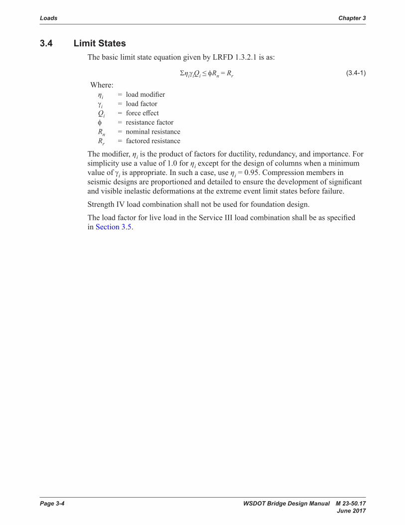
Page 3-4 WSDOT Bridge Design Manual M 23-50.17 June 2017
3.4 LimitStatesThebasiclimitstateequationgivenbyLRFD1.3.2.1isas:
ΣηiγiQi≤φRn = Rr (3 .4-1)
Where:ηi = loadmodifierγi = load factorQi = forceeffectφ = resistance factorRn = nominalresistanceRr = factored resistance
Themodifier,ηiistheproductoffactorsforductility,redundancy,andimportance.Forsimplicityuseavalueof1.0forηiexceptforthedesignofcolumnswhenaminimumvalue of γiisappropriate.Insuchacase,useηi=0.95.Compressionmembersinseismicdesignsareproportionedanddetailedtoensurethedevelopmentofsignificantandvisibleinelasticdeformationsattheextremeeventlimitstatesbeforefailure.
StrengthIVloadcombinationshallnotbeusedforfoundationdesign.
TheloadfactorforliveloadintheServiceIIIloadcombinationshallbeasspecifiedin Section 3.5.
Chapter 3 Loads
WSDOT Bridge Design Manual M 23-50.17 Page 3-5 June 2017
3.5 LoadFactorsandLoadCombinationsThelimitstatesloadcombinations,andloadfactors(γi) used for structural design are in accordance with the AASHTOLRFDTable3.4.1-1.Forfoundationdesign,loadsarefactoredafterdistributionthroughstructuralanalysisormodeling.
ThedesignliveloadfactorfortheServiceIIILimitStateloadcombinationshallbeasfollows:
γLL=0.8whentherequirementsofSections5.6.1 and 5.6.2aresatisfiedandstressanalysisisbasedongrosssectionproperties.
γLL=1.0whentherequirementsofSections5.6.1 and 5.6.2aresatisfiedandstressanalysisisbasedontransformedsectionproperties.
InspecialcasesthatdeviatefromtherequirementsofSections5.6.1 and 5.6.2 and have beenapprovedbytheWSDOTBridgeDesignEngineer,γLL,shallbeasspecifiedintheAASHTO LRFD.
TheServiceIIIliveloadfactorforloadratingshallbe1.0.
TheliveloadfactorforExtremeEvent-ILimitStateloadcombination,γEQ as specifiedintheAASHTOLRFDTable3.4.1-1forallWSDOTbridgesshallbetakenequal to 0.50. The γEQfactorappliestotheliveloadforceeffectobtainedfromthebridgeliveloadanalysis.Associatedmassofliveloadneednotbeincludedinthedynamicanalysis.
TheAASHTOLRFDallowtheliveloadfactorinExtremeEvent-Iloadcombination,γEQ,bedeterminedonaprojectspecificbasis.Thecommentaryindicatesthatthepossibilityofpartialliveload,i.e.,γEQ<1.0,withearthquakesshouldbeconsidered.TheapplicationofTurkstra’sruleforcombininguncorrelatedloadsindicatesthatγEQ =0.50isreasonableforawiderangeofvaluesofaveragedailytrucktraffic(ADTT).TheNCHRPReport489recommendsliveloadfactorforExtremeEvent-ILimitState,γEQ equal to 0.25 for all bridges. This factor shall be increased to γEQ equal to 0.50 for bridgeslocatedinmainstateroutesandcongestedroads.
Sincethedeterminationofliveloadfactor,γEQ based on ADTT or based on bridges locatedincongestedroadscouldbeconfusingandquestionable,itisdecidedthatliveload factor of γEQ equal to 0.50 to be used for all WSDOT bridges regardless the bridge location or congestion.
Thebaseconstructiontemperaturemaybetakenas64°FforthedeterminationofTemperatureLoad.
The load factors γTG and γSEaretobedeterminedonaprojectspecificbasisinaccordance with Articles 3.4.1 and 3.12 of the AASHTO LRFD. Load Factors for PermanentLoads,γpareprovidedinAASHTOLRFD Table 3.4.1-2.
TheloadfactorfordowndragloadsshallbeasspecifiedintheAASHTOLRFD Table 3.4.1-2.TheGeotechnicalReportwillprovidethedowndragforce(DD). The down dragforce(DD)isaloadappliedtothepile/shaftwiththeloadfactorspecifiedintheGeotechnicalReport.Generally,liveloads(LL) are less than the down drag force and shouldbeomittedwhenconsideringdowndragforces.
Loads Chapter 3
Page 3-6 WSDOT Bridge Design Manual M 23-50.17 June 2017
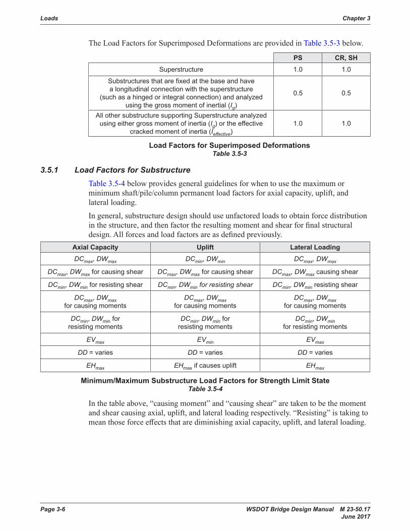
TheLoadFactorsforSuperimposedDeformationsareprovidedinTable 3.5-3 below.
PS CR,SHSuperstructure 1 .0 1 .0
Substructures that are fixed at the base and have a longitudinal connection with the superstructure
(such as a hinged or integral connection) and analyzed using the gross moment of inertial (Ig)
0 .5 0 .5
All other substructure supporting Superstructure analyzed using either gross moment of inertia (Ig) or the effective
cracked moment of inertia (Ieffective)1 .0 1 .0
LoadFactorsforSuperimposedDeformationsTable 3.5-3
3.5.1 Load Factors for SubstructureTable 3.5-4belowprovidesgeneralguidelinesforwhentousethemaximumorminimumshaft/pile/columnpermanentloadfactorsforaxialcapacity,uplift,andlateral loading.
Ingeneral,substructuredesignshoulduseunfactoredloadstoobtainforcedistributioninthestructure,andthenfactortheresultingmomentandshearforfinalstructuraldesign.Allforcesandloadfactorsareasdefinedpreviously.
AxialCapacity Uplift LateralLoadingDCmax, DWmax DCmin, DWmin DCmax, DWmax
DCmax, DWmax for causing shear DCmax, DWmax for causing shear DCmax, DWmax causing shear
DCmin, DWmin for resisting shear DCmin, DWmin for resisting shear DCmin, DWmin resisting shear
DCmax, DWmax for causing moments
DCmax, DWmax for causing moments
DCmax, DWmax for causing moments
DCmin, DWmin for resisting moments
DCmin, DWmin for resisting moments
DCmin, DWmin for resisting moments
EVmax EVmin EVmax
DD = varies DD = varies DD = varies
EHmax EHmax if causes uplift EHmax
Minimum/MaximumSubstructureLoadFactorsforStrengthLimitStateTable 3.5-4
Inthetableabove,“causingmoment”and“causingshear”aretakentobethemomentandshearcausingaxial,uplift,andlateralloadingrespectively.“Resisting”istakingtomeanthoseforceeffectsthatarediminishingaxialcapacity,uplift,andlateralloading.

Chapter 3 Loads
WSDOT Bridge Design Manual M 23-50.17 Page 3-7 June 2017
3.6 LoadsandLoadFactorsforConstructionUnlessotherwisespecified,theloadfactorforconstructionloadsandforanyassociateddynamiceffectsshallnotbelessthan1.5inStrengthI.TheloadfactorforwindinStrengthIIIshallnotbelessthan1.25.
WheninvestigatingStrengthLoadCombinationsI,III,andVduringconstruction,loadfactorsfortheweightofthestructureandappurtenances,DC and DW,shallnot be taken to be less than 1.25.
Whereevaluationofconstructiondeflectionsarerequiredbythecontractdocuments,LoadCombinationServiceIshallapply.Constructiondeadloadsshallbeconsideredaspartofthepermanentloadandconstructiontransientloadsconsideredpartoftheliveload.Theassociatedpermitteddeflectionsshallbeincludedinthecontractdocuments.
Forfalseworkandformworkdesignloads,seeStandard Specifications Section6-02.3(17)A.Thebaseconstructiontemperatureshallbetakenas64°FforthedeterminationofTemperatureLoad.
Loads Chapter 3
Page 3-8 WSDOT Bridge Design Manual M 23-50.17 June 2017
3.7 LoadFactorsforPost-tensioning3.7.1 Post-tensioningEffectsfromSuperstructure
Whencast-in-place,post-tensionedsuperstructureisconstructedmonolithicwiththepiers,thesubstructuredesignshouldtakeintoaccountframemomentsandshearscausedbyelasticshorteningandcreepofthesuperstructureuponapplicationoftheaxialpost-tensioningforceatthebridgeends.Framemomentsandshearsthusobtainedshouldbeaddedalgebraicallytothevaluesobtainedfromtheprimaryandsecondarymomentdiagramsappliedtothesuperstructure.
Whencast-in-place,post-tensionedsuperstructurearesupportedonslidingbearingsatsomeofthepiers,thedesignofthosepiersshouldincludethelongitudinalforcefromfrictiononthebearingsgeneratedasthesuperstructureshortensduringjacking.Whenpost-tensioningiscomplete,thefullpermanentreactionfromthiseffectshouldbeincludedinthegoverningAASHTOloadcombinationsforthepierunderdesign.
3.7.2 SecondaryForcesfromPost-tensioning,PSTheapplicationofpost-tensioningforcesonacontinuousstructureproducesreactionsatthestructure’ssupportandinternalforcesthatarecollectivelycalledsecondary forces.
Secondaryprestressingforces(i.e.secondarymoments)aretheforceeffectsincontinuousmembers,asaresultofcontinuouspost-tensioning.Inframeanalysissoftware,thesecondarymomentsaregenerallyobtainedbysubtractingtheprimarymoment(P*e)fromthetotalPSmomentobtainedbyapplyinganequivalentstaticloadwhichrepresentstheforcesduetopost-tensioning.Aloadfactor,γPS,of1.0isappropriateforthesuperstructure.Forfixedcolumnsa50percentreductioninPSforceeffectscouldbeusedgiventheelasto-plasticcharacteristicsofthesoilsurroundingthefoundationelements.
Chapter 3 Loads
WSDOT Bridge Design Manual M 23-50.17 Page 3-9 June 2017
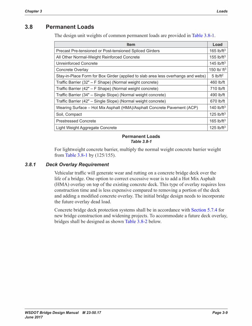
3.8 PermanentLoadsThedesignunitweightsofcommonpermanentloadsareprovidedinTable 3.8-1.
Item LoadPrecast Pre-tensioned or Post-tensioned Spliced Girders 165 lb/ft3
All Other Normal-Weight Reinforced Concrete 155 lb/ft3
Unreinforced Concrete 145 lb/ft3
Concrete Overlay 150 lb/ ft3
Stay-in-Place Form for Box Girder (applied to slab area less overhangs and webs) 5 lb/ft2
Traffic Barrier (32″ – F Shape) (Normal weight concrete) 460 lb/ftTraffic Barrier (42″ – F Shape) (Normal weight concrete) 710 lb/ftTraffic Barrier (34″ – Single Slope) (Normal weight concrete) 490 lb/ftTraffic Barrier (42″ – Single Slope) (Normal weight concrete) 670 lb/ftWearing Surface – Hot Mix Asphalt (HMA)/Asphalt Concrete Pavement (ACP) 140 lb/ft3
Soil, Compact 125 lb/ft3
Prestressed Concrete 165 lb/ft3
Light Weight Aggregate Concrete 125 lb/ft3
PermanentLoadsTable 3.8-1
Forlightweightconcretebarrier,multiplythenormalweightconcretebarrierweightfromTable 3.8-1by(125/155).
3.8.1 DeckOverlayRequirementVehiculartrafficwillgeneratewearandruttingonaconcretebridgedeckoverthelifeofabridge.OneoptiontocorrectexcessivewearistoaddaHotMixAsphalt(HMA)overlayontopoftheexistingconcretedeck.Thistypeofoverlayrequireslessconstructiontimeandislessexpensivecomparedtoremovingaportionofthedeckandaddingamodifiedconcreteoverlay.Theinitialbridgedesignneedstoincorporatethe future overlay dead load.
ConcretebridgedeckprotectionsystemsshallbeinaccordancewithSection 5.7.4 for newbridgeconstructionandwideningprojects.Toaccommodateafuturedeckoverlay,bridges shall be designed as shown Table 3.8-2 below.
Loads Chapter 3
Page 3-10 WSDOT Bridge Design Manual M 23-50.17 June 2017
3.9 LiveLoads3.9.1 Design Live Load
Liveloaddesigncriteriaarespecifiedinthelowerrightcornerofthebridgepreliminaryplansheet.TheBridgePreliminaryPlanEngineerdeterminesthecriteriausingthefollowingguideline:• New bridges and Bridge widening with addition of substructure – HL-93• Bridgesuperstructurewideningwithnoadditionofsubstructure–Liveloadcriteria
of the original design• Detourandothertemporarybridges–75percentofHL-93
TheapplicationofdesignvehicularliveloadsshallbeasspecifiedinAASHTOLRFD3.6.1.3.Thedesigntandem,or“lowboy”,definedinLRFDC3.6.1.1shall be included in the design vehicular live load.
TheeffectofonedesigntandemcombinedwiththeeffectofthedesignlaneloadspecifiedinLRFDArticle3.6.1.2.4and,fornegativemomentbetweenthepointsofcontraflexureunderauniformloadonallspansandreactionsatinteriorsupports,shallbeinvestigatedadualdesigntandemspacedfrom26.0feetto40.0feetapart,measuredbetweenthetrailingaxleoftheleadvehicleandtheleadaxleofthetrailingvehicle,combinedwiththedesignlaneload.Forthepurposeofthisarticle,thepairsofthedesigntandemshallbeplacedinadjacentspansinsuchpositiontoproducemaximumforceeffect.Axlesofthedesigntandemthatdonotcontributetotheextremeforceeffectunderconsiderationshallbeneglected..
3.9.2 LoadingforLiveLoadDeflectionEvaluationTheloadingforliveloaddeflectioncriteriaisdefinedinLRFDArticle3.6.1.3.2.LiveloaddeflectionsfortheServiceIlimitstateshallsatisfytherequirementsofLRFD Section 2.5.2.6.2.
3.9.3 Distribution to SuperstructureA. Multi Girder Superstructure
Theliveloaddistributionfactorforexteriorgirderofmultigirderbridgesshallbeasfollows:• Forexteriorgirderdesignwithslabcantileverlengthequalorlessthan40percentoftheadjacentinteriorgirderspacing,usetheliveloaddistributionfactorforinteriorgirder.Theslabcantileverlengthisdefinedasthedistancefromthecenterlineoftheexteriorgirdertotheedgeoftheslab.
• Forexteriorgirderdesignwithslabcantileverlengthexceeding40percentoftheadjacentinteriorgirderspacing,usetheleverrulewiththemultiplepresencefactorof1.0forsinglelanetodeterminetheliveloaddistribution.Theliveloadusedtodesigntheexteriorgirdershallnotbelessthantheliveloadusedfortheadjacentinteriorgirder.
• ThespecialanalysisbasedontheconventionalapproximationofloadsonpilesasdescribedinLRFDArticleC4.6.2.2.2dshallnotbeusedunlesstheeffectivenessofdiaphragmsonthelateraldistributionoftruckloadis investigated.
Chapter 3 Loads
WSDOT Bridge Design Manual M 23-50.17 Page 3-11 June 2017
B. Concrete Box Girders
Theloaddistributionfactorformulti-cellcastinplaceconcreteboxgirdersshallbeperAASAHTOLRFDforinteriorgirdersfromTable4.6.2.2.2b-1forbendingmoment,andTable4.6.2.2.3a-1forshear.Theliveloaddistributionfactorforinteriorgirdersshallthenbemultipliedbythenumberofwebstoobtainthedesignliveloadfortheentiresuperstructure.Theliveloaddistributionneednotexceedthetotalnumberofdesignlanes. The correction factor for live load distribution forskewedsupportasspecifiedinTables4.6.2.2.2e-1forbendingmomentand4.6.2.2.3c-1 for shear shall be considered.
DF = Nb xDfiLiveloaddistributionfactorformulti-cellboxgirder (3 .9 .4-1)Where:
Dfi = Live load distribution factor for interior web Nb = Numberofwebs
C. Multiple Presence Factors
Areductionfactorwillbeappliedinthesubstructuredesignformultipleloadingsin accordance with AASHTO.
D. Distribution to Substructure
Thenumberoftrafficlanestobeusedinthesubstructuredesignshallbedeterminedbydividingtheentireroadwayslabwidthby12.Nofractionallanesshallbeused.Roadwayslabwidthsoflessthan24feetshallhaveamaximumoftwo design lanes.
E. Distribution to Crossbeam
Thedesignandloadratingliveloadingisdistributedtothesubstructurebyplacingwheellinereactionsinlaneconfigurationsthatgeneratethemaximumstressinthe substructure. A wheel line reaction is one-half of the reaction of a single lane ofliveload.Forintegralandhingedcontinuitydiaphragms,liveloadsareconsid-ered to act directly on the substructure without further distribution through the superstructureasillustratedinFigure 3.9-1.Forgirderconfigurationswherethereisaclearloadpaththroughthegirderstothecrossbeam,suchasatexpansionpierswithgirderssupportedonindividualbearings,liveloadreactionsareappliedthroughthebearings.Normally,substructuredesignwillnotconsiderliveloadtorsionorlateraldistribution.Sideswayeffectsshallbetakenintoaccount.

Loads Chapter 3
Page 3-12 WSDOT Bridge Design Manual M 23-50.17 June 2017
WHEEL LINE LOADS APPLIEDTO SUPERSTRUCTURE
WHEEL LINE LOADS APPLIEDTO SUBSTRUCTURE
CROSSBEAM
CROSSBEAM
LIVE LOAD ON BRIDGE SECTION
LiveLoadDistributiontoSubstructureFigure 3.9-1
Forsteelandprestressedconcretesuperstructurewheretheliveloadistransferredtosubstructurethroughbearings,crossframesordiaphragms,thegirderreactionmaybeusedforsubstructuredesign.Liveloadplacementisdependentonthememberunderdesign.Someexamplesofliveloadplacementareasfollows.Theexteriorvehiclewheelisplaced2feetfromthecurbformaximumcrossbeamcantilevermomentormaximumeccentricfoundationmoment.
Forcrossbeamdesignbetweensupports,thelanesareplacedtoobtainthemaximumpositivemomentinthemember;thenre-locatedtoobtainthemaximumshearornegativemomentinthemember.
Forcolumndesign,thedesignlanesareplacedtoobtainthemaximumtransversemomentatthetopofthecolumn;thenre-locatedtoobtainthemaximumaxialforceofthecolumn.

Chapter 3 Loads
WSDOT Bridge Design Manual M 23-50.17 Page 3-13 June 2017
3.9.4 Bridge Load RatingBridgedesignersareresponsibleforDesign,Legal,andPermitloadratingofnewbridgesinaccordancewiththeNationalBridgeInspectionStandards(NBIS)andtheAASHTO Manual Bridge Evaluation. See Chapter13 fordetailedinformationonloadingrequirementsforbridgeloadrating.
SuperstructureTypeConcreteCover
Overlayshownintheplan
FutureDesignOverlay
DeckProtectionSystems1and4:• Precast concrete, steel I or box girder
with cast-in-place slab• Precast slabs with cast-in-place slab• Reinforced and post-tensioned box
beams and slab bridges• Mainline Bridges on State Routes
2½″ (Including ½″ wearing
surface)None 2″ HMA
DeckProtectionSystems1and4:• Undercrossing bridge that carries traffic
from a city street or county road• Bridges with raised sidewalks
2½″ (Including ½″ wearing
surface)None None
DeckProtectionSystem2:• Concrete Overlays
Varies Varies None
DeckProtectionSystem3:• HMA Overlays
Varies Varies None
DeckProtectionSystem5:• Segmental bridges• Bridge Decks with longitudinal or
transverse post-tensioning
1¾″ (Including ¼″ wearing
surface)
1½″ Modified Concrete Overlay
None
BridgeOverlayRequirementsTable 3.8-2
Theeffectofthefuturedeckoverlayongirderscamber,“A”dimension,creep,andprofilegradeneednotbeconsideredinsuperstructuredesign.
Deckoverlaymayberequiredatthetimeoforiginalconstructionforsomebridgewideningorstagedconstructionprojectsifridequalityisamajorconcern.
Loads Chapter 3
Page 3-14 WSDOT Bridge Design Manual M 23-50.17 June 2017
3.10 PedestrianLoadsPedestrianbridgesshallbedesignedinaccordancewiththerequirementsoftheAASHTO LFRD Guide Specifications for the Design of Pedestrian Bridges,datedDecember2009.
SeismicdesignofpedestrianbridgesshallbeperformedinaccordancewiththerequirementsoftheAASHTOSEISMIC.
PedestrianliveloadonvehicularbridgeshallbeasspecifiedinLRFD3.6.1.6.

Chapter 3 Loads
WSDOT Bridge Design Manual M 23-50.17 Page 3-15 June 2017
3.11 WindLoads3.11.1 Wind Load to Superstructure
Fortheusualgirderandslabbridgeshavingindividualspanlengthofnotmorethan150ftandamaximumheightof33feetabovelowgroundorwaterlevel,thefollowingsimplifiedwindpressureonstructure(WS),couldbeusedinlieuofthegeneralmethoddescribedinAASHTOLRFDArticle3.8.1.2:
Limit State
WindExposureCategoryB C D
Transverse Longitudinal Transverse Longitudinal Transverse LongitudinalStrength III 0 .029 0 .007 0 .040 0 .010 0 .046 0 .012Strength V 0 .021 0 .005 0 .021 0 .005 0 .021 0 .005Service I 0 .016 0 .004 0 .016 0 .004 0 .016 0 .004
Service IV 0 .016 0 .004 0 .023 0 .006 0 .026 0 .007
WindPressure(kippersquarefoot)Table3.11.1-1
Bothforcesshallbeappliedsimultaneously.
Fortheusualgirderandslabbridgeshavingindividualspanlengthofnotmorethan150feetandamaximumheightof33feetabovelowgroundorwaterlevel,thefollowingsimplifiedwindpressureonvehicle(WL),couldbeusedinlieuofthegeneralmethoddescribedinAASHTOLRFDArticle3.8.1.3:• 0.10kipperlinearfoot,transverse• 0.04kipperlinearfoot,longitudinal
Bothforcesshallbeappliedsimultaneously.
3.11.2 Wind Load to SubstructureWindforcesshallbeappliedtothesubstructureunitsinaccordancewiththeloadingsspecifiedinAASHTO.Transversestiffnessofthesuperstructuremaybeconsidered,asnecessary,toproperlydistributeloadstothesubstructureprovidedthatthesuperstructureiscapableofsustainingsuchloads.Verticalwindpressure,perAASHTOLRFDSection3.8.2,shallbeincludedinthedesignwhereappropriate,forexample,onsinglecolumnpiers.Windloadsshallbeappliedthroughshearkeysorotherpositivemeansfromthesuperstructuretothesubstructure.Windloadsshallbedistributedtothepiersandabutmentsinaccordancewiththelawsofstatics.Transversewindloadscanbeapplieddirectlytothepiersassumingthesuperstructuretoactasarigidbeam.Forlargestructuresamoreappropriateresultmightbeobtainedbyconsideringthesuperstructuretoactasaflexiblebeamonelasticsupports.
3.11.3 Wind on Noise WallsWindonNoiseWallsshallbeasspecifiedinLRFD3.8.1,3.8.1.2.4,and15.8.2.
Loads Chapter 3
Page 3-16 WSDOT Bridge Design Manual M 23-50.17 June 2017
3.12 LoadsonCulvertsLoads and live load distributions on culverts shall be in accordance with the requirementsoftheAASHTOLRFD.SeismicloadingshallbeanalyzedaccordingtoFHWA-NHI-10-034“Technical Manual for Design and Construction of Roadway Tunnels – Civil Elements”.
Chapter 3 Loads
WSDOT Bridge Design Manual M 23-50.17 Page 3-17 June 2017
3.13 EarthquakeEffectsEarthquake loads see Chapter4.

Loads Chapter 3
Page 3-18 WSDOT Bridge Design Manual M 23-50.17 June 2017
3.14 EarthPressureEarth Pressure loads see Chapter7.
Chapter 3 Loads
WSDOT Bridge Design Manual M 23-50.17 Page 3-19 June 2017
3.15 ForceEffectsDuetoSuperimposedDeformationsPS,CR,SH,TUandTGaresuperimposeddeformations.LoadfactorsforPS,CR,and SH,areasshowninTable 3.5-3.Innon-segmentalstructures:PS,CR, and SH aresymbolicallyfactoredbyavalueof1.0inthestrengthlimitstate,butareactuallydesignedforintheservicelimitstate.Forsubstructureinthestrengthlimitstate,thevalue of 0.50 for γPS,γCR,γSH,andγTUmaybeusedwhencalculatingforceeffectsinnon-segmentalstructures,butshallbetakeninconjunctionwiththegrossmomentofinertiainthecolumnsorpiers.Thelargerofthevaluesprovidedforloadfactorof TUshallbeusedfordeformationsandthesmallervaluesforallothereffects.ThecalculationofdisplacementsforTUloadsutilizesafactorgreaterthan1.0toavoidundersizingjoints,expansiondevices,andbearings.
The current AASHTO LRFD require a load factor of 1.2 on CR,SH,andTU deformations,and0.5onotherCR/SH/TUforceeffects.Thelowervaluehadbeenrationalizedasdissipationoftheseforceeffectsovertime,particularlyinthecolumnsandpiers.
Changingtheloadfactorsforcreepandshrinkageisnotstraight-forwardbecauseCR,SHare“superimposeddeformations”,thatis,forceeffectsduetoachangeinmaterialbehaviorthatcauseachangeinthestaticalsystem.Forsafetyandsimplicityindesign,theyaretreatedasloads--despitenotbeingmeasurableattimet=0.However,behaviorisnonlinearandapplicationoftheloadfactormustalsobeconsidered.Somesoftwarewillrunserviceloadanalysistwice:oncewithandoncewithoutCR,SH effects.TheCR and SH can then be isolated by subtracting the results of the two runs. OthersoftwarewillcoupletheCR and SHwiththedeadload,givingashrinkage-orcreep-adjusteddeadload.
Theproposedcompromiseistoassigncreepandshrinkagethesameloadfactorasthe DCloads,butpermitafactorof1.0iftheproject-specificcreepcoefficientcanbedeterminedandisthenusedinthelinearanalysissoftware.
Thermalandshrinkageloadingsareinducedbymovementsofthestructureandcanresultfromseveralsources.Movementsduetotemperaturechangesarecalculatedusingcoefficientsofthermalexpansionof0.000006feet/footperdegreeforconcreteand0.0000065feet/footperdegreeforsteel.Reinforcedconcreteshrinksattherateof0.0002feet/foot.
Loads Chapter 3
Page 3-20 WSDOT Bridge Design Manual M 23-50.17 June 2017
3.16 OtherLoads3.16.1 Buoyancy
Theeffectsofsubmergenceofaportionofthesubstructureistobecalculated,bothfordesigningpilingforupliftandforrealizingeconomyinfootingdesign.
3.16.2 Collision Force on Bridge SubstructureSee AASHTO LRFD Articles 3.6.5 and 3.14
3.16.3 CollisionForceonTrafficBarrierSee AASHTO LRFD Article 3.6.5.1
3.16.4 ForcefromStreamCurrent,FloatingIce,andDriftSee AASHTO LRFD Article 3.9
3.16.5 IceLoadInaccordancewithWSDOTHQHydraulicsOfficecriteria,anicethicknessof12″shallbeusedforstreamflowforcesonpiersthroughoutWashingtonState.
3.16.6 UniformTemperatureLoadThedesignthermalmovementassociatedwithauniformtemperaturechangemaybecalculatedusingtherangesoftemperatureasspecifiedherein.Thetemperaturerangesshownbelowreflectthedifferencebetweentheextendedlowerandupperboundarytobeusedtocalculatethermaldeformationeffects.• ConcreteBridges(AllRegions): 0°to100°• SteelBridges(EasternWashington): −30°to120°• SteelBridges(WesternWashington): 0°to120°
Chapter 3 Loads
WSDOT Bridge Design Manual M 23-50.17 Page 3-21 June 2017
3.99 References1. AASHTO LRFD Bridge Design Specifications for Design of Highway Bridges,
7th Edition.

Loads Chapter 3
Page 3-22 WSDOT Bridge Design Manual M 23-50.17 June 2017