chapter 3: the house as a system - university … 3 the...24 chapter 3: the house as a system...
TRANSCRIPT

Chapter 3: The House as a System 21
CHAPTER 3: THE HOUSE AS A SYSTEM
It is common to think of houses as independent structures, placed on an attractive lot; however, the house and lot combine to form a complex system of related components. The actual house, the outside environment and the indoor environment must function as a unit. When properly designed, each part functions to provide a safe, comfortable and healthy living environment for the occupants. Amid fluctuating temperatures, moisture levels, and air pressures, the house’s systems are designed and built to minimize problems. The interrelationship of these systems sometimes produces surprising and unforeseen consequences.

22 Chapter 3: The House as a System
HOUSEHOLD ENVIRONMENT
A house’s many assets can quickly be diminished by persistent environmental problems. Most homes will have problems in some part of the system. These environmental problems could range from being merely minor nuisances to being life threatening. Some frequent problems found in Kentucky homes are:
Mold on walls, ceilings, and furnishings Mysterious odors Excessive heating and cooling bills High humidity Rooms that are never comfortable Decayed structural wood and other materials Termite or other pest infestations Fireplaces that do not draft properly High levels of formaldehyde, radon or carbon monoxide Water leaks Wet basements
When any of these problems occur, the house has not reacted properly to the outdoor or indoor environment. Viewing the house and the lot as a complex unit will increase the likelihood of the construction of a durable, healthy, energy efficient structure.
The following factors help define the quality of the living environment. If kept at desirable levels, the house will provide comfort and healthy air quality.
Temperature—measured by a regular thermometer. Relative humidity levels—high humidity causes discomfort and can promote growth of mold and
organisms, such as dust mites. Air quality—the level of pollutants in the air, such as formaldehyde, radon, carbon monoxide, and
other detrimental chemicals, as well as organisms such as mold, pollen, and dust mites. The key cause of air quality problems is the strength of the source of pollution.
Air movement—the velocity at which air flows in specific areas of the home. Higher velocities make occupants more comfortable in summer, but less comfortable in winter. Air moving through many common types of insulation can reduce insulating values.
Health, comfort, and energy bills are affected considerably by how readily heat moves through a home and its exterior envelope. New homes are required to meet energy codes, which require insulation on all exterior surfaces—floors, walls, and ceilings. While there is a wide variation in the percentages of where heat is lost and gained in the building envelope, Table 3-1 shows the percentage that each of the building components contributes to the heat loss and gain of a typical home that meets the energy code (Code Home used in previous illustrations). Energy efficient improvements can be made to reduce these levels. Duct losses to the outside can be eliminated by locating the ducts inside the building envelope; proper sealing of the building envelope can reduce infiltration and mechanical ventilation can be used to control indoor air quality.

Chapter 3: The House as a System 23
In summer, cooling needs are primarily determined by the location and shading of windows. In addition, the percentage of the cooling load that is for latent cooling (humidity removal) can increase substantially in homes with a well-insulated thermal envelope. The major sources of moisture, some of which can be controlled, include cooking activities, human respiration and perspiration, large amounts of indoor plants and infiltration of hot, humid, exterior air. Tighter homes have reduced humidity levels in summer.
THINGS TO KNOW ‐ BASIC CONCEPTS
Before actually building an energy efficient home, it is important to understand four basic concepts that relate to all components of the design and construction. The movement of heat, air, and moisture, plus relative humidity influences the comfort and health of the home dwellers.
HOW HEAT MOVES IN HOMES
Conduction is the transfer of heat through solid objects, such as the ceilings, walls, and floors of a home. Insulation (and multiple layers of glass in windows) reduces conduction losses. The direction of heat flow is from hot to cold. Figure 3-1 shows conduction from a warm interior to a cooler outdoors.
Table 3-1 Percentage of Energy Use by Components of the Building Envelope
Components Code Home1
HERS = 98
Ceiling 3%
Walls 22%
Doors 1%
Windows 25%
Floor 5%
Infiltration 25%
Ducts 19% 1 A two-story, 2,000 sq ft home in Lexington, KY, exactly meeting the 2006 International Energy Conservation Code.
Figure 3 – 1 Conduction Heat Transfer

24 Chapter 3: The House as a System
Convection is the flow of heat by currents of air. Air currents are caused by wind pressure differences, stirring fans, and air density changes as the air heats and cools (Figure 3-2). As air becomes heated, it becomes less dense and rises; as air cools, it becomes more dense and sinks.
Radiation is the movement of energy in electromagnetic waves from warm to cooler objects across empty spaces, such as radiant heat traveling from the roof deck to the attic insulation on a hot sunny day (Figure 3-3).
HOW AIR MOVES IN HOMES
Air movement is influenced by air leakage. Conditions for air leakage to occur are:
Holes—the larger the hole, the greater the air leakage. Large holes have higher priority for air sealing efforts, and
Driving force—a pressure difference that forces air to flow through a hole. Holes that experience stronger and more continuous driving forces have higher priority for sealing efforts.
The common driving forces are:
Wind—caused by weather conditions. Stack effect—upward air pressure due to the buoyancy of air. Mechanical blower—induced pressure imbalances caused by operation of fans and blowers.
Figure 3 – 2 Convection Heat Transfer
Figure 3 – 3 Radiation Heat Transfer

Chapter 3: The House as a System 25
WIND
Wind is usually considered to be the primary driving force for air leakage in mild climates. When the wind blows against a building, it creates a high pressure zone on the windward areas. Outdoor air from the windward side infiltrates the building while air exits on the leeward side. Wind acts to create areas of differential pressure that cause both infiltration and exfiltration. Figure 3-4 illustrates both the higher pressure (+) on the windward side and the lower pressure (–) on the leeward side. The degree to which wind contributes to air leakage depends on its velocity and duration. Most homes have only small cracks on the exterior.
On average, winds typically found in the southeastern U.S. create a pressure difference of 10 to 20 Pascals on the windward and leeward sides of a house.
STACK EFFECT
The temperature difference between inside and outside causes warm air inside the home to rise while cooler air falls, creating a driving force known as the “stack effect” (Figure 3-5). The stack effect is what causes a chimney to operate. As heated air rises, it will escape through any opening in the upper area of the home and air will be drawn in at a lower level. The stack effect is weak but always present. Most homes have large access holes into the attic, crawl space or basement. Because the stack effect is so prevalent and the holes through which it drives air are often so large, it is usually a major contributor to air leakage, moisture, and air quality problems especially in winter.
Windward Leeward

26 Chapter 3: The House as a System
The stack effect can create pressure differences between 1 to 3 Pascals due to just the power of rising warm air. Crawl space and attic openings are often large.
MECHANICAL
Poorly designed and improperly installed forced-air systems can create strong pressure imbalances inside the home (Figure 3-6), which can triple air leakage whenever the home heating and cooling system operates. In addition, unsealed ductwork located in attics and crawl spaces can draw pollutants and excess moisture into the home. Correcting duct leakage problems is critical when constructing an energy efficient home. For example, the HERS = 98 home in Table 3-1 could save $61 per year by reducing its duct loss by 50% from 120 cfm to 60 cfm.
Air pressure is typically expressed in inches of water or Pascals. The pressure exerted by 0.004 inches of water equals one Pascal. The reason that Pascals is more frequently used than inches of water in air infiltration measurements, as a measurement of air pressure, is that the Pascal measurement simply uses larger numbers. The home building industry uses both measurement systems. Inches of water are commonly used for HVAC equipment and duct pressure measurements. Pascals are commonly used for the very low pressure measurements of air caused by wind, etc.
Figure 3 – 5 Stack Effect

Chapter 3: The House as a System 27
Leaks in supply and return ductwork can cause pressure differences of up to 30 Pascals. Exhaust equipment, such as kitchen fans, bath fans, and clothes dryers can also create pressure differences.
HOW MOISTURE MOVES IN HOMES
There are four primary modes of moisture migration into our homes. Each must be controlled to preserve comfort, health, and durability. Most moisture problems are challenging to diagnose because one or all of the four primary modes of moisture movement may factor into the problem. This chapter concludes with three problems, two of which involve the interaction and interrelationship of moisture transport modes.
1) BULK MOISTURE TRANSPORT
Bulk moisture transport is the flow of water through holes, cracks, and gaps.
Its primary source is rain. Causes include:
poor flashing; inadequate roof drainage; poor quality weather-stripping, or caulking
around joints in building exterior (such as windows, doors, and bottom plates); and
groundwater seepage due to adjacent ground not being sloped away from the house.
Any problems are solved through quality construction with durable materials.
This is the most important of the four modes of moisture migration (Figure 3-7).

28 Chapter 3: The House as a System
2) CAPILLARY ACTION
Capillary action is the wicking of water through porous materials or between small cracks.
Its primary sources are from rain or ground water.
Causes include: water seeping between overlapping
pieces of exterior siding; water drawn upward through pores or
cracks in concrete slabs and walls made of concrete or concrete block; and
water migrating from crawl spaces into floor and wall framing.
Any problems are solved by completely sealing pores or gaps, increasing the size of the gaps (usually to a minimum of ⅛ inch), or installing a waterproof, vapor barrier material to form a capillary break (see Figure 3-8).
3) AIR TRANSPORT
Air transport is the flow of air, containing water vapor, into enclosed areas through unsealed penetrations or joints between conditioned and unconditioned areas. As shown in Figure 3-9, air transport can bring 50 to 100 times more moisture into wall cavities than vapor diffusion.
Its primary source of moisture is the water vapor in air.
Causes include: air leaking through holes and cracks; other leaks between interior air and enclosed
wall cavities; interior air and attics; exterior air adding humidity to interior air in
summer; and crawl spaces and interior air.
Any problems are solved by creating an air barrier system.
Figure 3 – 9 Air Transport of Water Vapor

Chapter 3: The House as a System 29
4) VAPOR DIFFUSION
Vapor diffusion is the movement of water vapor in air through permeable materials. A perm at 73.4°F (23°C) is a measure of the number of grains of water vapor passing through a square foot of material per hour at a differential vapor pressure equal to one inch of mercury. Any material with a perm rating of less than 1.0 is considered a vapor retarder.
Its primary source is water vapor in the air. Causes include:
interior moisture permeating wall and ceiling finish materials; exterior moisture moving into the home in summer; and crawl space air moisture migrating through the floor into the home.
Any problems are solved by proper installation of a vapor retarder. The common term is “vapor barrier;” however, few materials are actual vapor barriers. Vapor retarders are not required in Climate Zone 4 but are required in Climate Zones 5 and higher.
This is the least important of the four modes of moisture migration, in Climate Zone 4.
RELATIVE HUMIDITY
Air is made up of gases (oxygen, nitrogen, etc.) and water vapor. The amount of water vapor that air can hold is determined by its temperature. Warm air can hold more water vapor than cold air. The amount of water vapor in the air is measured by its relative humidity. At 100% relative humidity (RH), water vapor condenses into a liquid. The temperature at which the water vapor in the air condenses is its dew point. Therefore, the dew point of air depends on its temperature and relative humidity. Preventing condensation involves either reducing the relative humidity of the air or increasing the temperatures of surfaces exposed to the air.
Determining the relative humidity is important when trying to check the performance of heating and cooling equipment or determining the cause of problems. The least expensive device for measuring relative humidity is the sling psychrometer. This device has two glass thermometers, one with a cotton wick on the thermometer bulb. To determine humidity, this wick is wet with clean water. Then, in order to move air across the two bulbs, the psychrometer is either twirled, for about a minute, by the handle or put in a fan draft. One thermometer will read the dry bulb temperature, and the other will read the wet bulb temperature. Charts permit the dry and wet bulb temperatures to be used to reliably and accurately determine relative humidity.
Digital relative humidity sensors are also available and can be simpler to use in locations such as a supply air duct. The readings are typically displayed as a digital readout, so additional charts are not required. They are often combined with a temperature sensor so that both measurements can be taken at the same time. Digital sensors can be contained in small data loggers, which allow measurements to be taken as often as every minute over several days. This can be important when assessing problems that occur infrequently.
A convenient tool for examining how temperature, moisture, and air interact is a psychrometric chart. A psychrometric chart aids in understanding the dynamics of moisture control. A simplified chart, shown in Figure 3-10, relates temperature and moisture. Temperature increases from left to right and the amount of moisture in the air increases from the bottom up. The upper left curve of the chart is the 100% relative humidity line. Air can hold no additional water vapor at that temperature, which is the dew point. If the air temperature goes below the dew point temperature, condensation will occur.

30 Chapter 3: The House as a System
WHY INDOOR AIR IS DRY IN WINTER
Air leaking into a residence, in winter, will reduce the humidity levels in a home. For example, if outside air, at 30°F and 80% relative humidity leaks into a home, the air will warm up to the indoor temperature of 70°F. However, the relative humidity of this warmed air would only be about 18%.
A psychrometric chart can show why this happens. Match the step number (1 and 2) with the same number on the graph in Figure 3-10.
1. Find the point (1) representing the outdoor air conditions (30°F at 80% RH). 2. Draw a horizontal line to 70°F and read the relative humidity, 18%.
WINTER CONDENSATION IN WALLS
In a well-built wall, the temperature of the inside surface of the sheathing will depend on the insulating value of the rest of the wall and the sheathing, and the indoor and outdoor temperatures. Consider the following example: if it is 35°F outside and 70°F at 40% relative humidity inside, then:
The interior surface of plywood sheathing would be around 39°F and The interior surface of insulated sheathing would be 47°F.
Figure 3 – 10 Psychrometric Chart

Chapter 3: The House as a System 31
The psychrometric chart can help predict whether condensation will occur in this example. Match the step number (1, 2, or 3) with the same number on the graph in Figure 3-11.
1. Find the point (1) representing the indoor air conditions (70°F at 40% RH). 2. Draw a horizontal line to the 100% RH line. 3. Draw a vertical line down from where the horizontal line intersects the 100% RH line to read
the dew point temperature, 44°F. In the example, condensation would occur if the temperature of the inside surface of the sheathing were at 44°F. Thus, under the temperature conditions in this example, water droplets may form on the plywood sheathing (which would be around 39°F), but not on the insulated sheathing (which would be around 47°F).
SUMMER CONDENSATION IN WALLS
Figure 3-12 depicts another moisture and relative humidity problem, only this time summer conditions exist. If the interior air is 75°F, and outside air at 95°F and 40% relative humidity enters the wall cavity, will condensation occur?
The psychrometric chart can help predict whether condensation will occur in this example. Match the step number (1, 2, or 3) with the same number on the graph in Figure 3-12.
Figure 3 – 11 Psychrometric Chart – Winter Dew Point

32 Chapter 3: The House as a System
1. Find the point (1) representing the outdoor air conditions (95°F at 40% RH). 2. Draw a horizontal line to the 100% RH line. 3. Draw a vertical line down from where the horizontal line intersects the 100% RH line to read the
dew point temperature, 67°F. In this example, because the drywall temperature (75°F) is greater than the dew point, condensation should not form.
EFFECT OF RELATIVE HUMIDITY
There are a variety of ways in which humans respond to changes in relative humidity:
Ideal health and comfort for humans occurs at 30% to 50% RH; At lower relative humidity levels, we feel cooler as moisture evaporates more readily from our
skin; At higher relative humidity levels, we may feel uncomfortable, especially at temperatures above
78°F; Dry air, less than 30% RH, can often aggravate respiratory and skin problems; Molds grow in air over 70% RH; Dust mites prosper at or above 50% RH, and Wood decays when the RH is near or at 100%.
Figure 3 – 12 Psychrometric Chart – Summer Dew Point Temperature on Inside Wall

Chapter 3: The House as a System 33
SYSTEMS IN A HOUSE
Whether the health and comfort factors of temperature, humidity, and air quality remain at comfortable and healthy levels depends on how well the home works as a system. Every home has the following systems that are intended to provide indoor health and comfort:
Structural system Thermal insulation system Air leakage control system Moisture control system Comfort control system provided by the HVAC system
STRUCTURAL SYSTEM
The purpose of this book is not to show how to design and build the structural components of a home, but rather to describe how to maintain the home’s integrity, while using energy efficient components. Key problems that can affect the structural integrity of a home include:
Frost heaving Erosion Rain water intrusion such as roof leaks Water absorption into building materials Excessive relative humidity levels Fire Summer heat build-up
To create and maintain the structural integrity of the home, the home designer and builder should:
Ensure that the footer is installed level and below the frost line. Install adequate reinforcing and make sure that the concrete has the proper slump and strength.
Divert ground water away from the building through a properly designed and installed foundation drainage system. Install effective gutters, downspouts, and rainwater drains.
Ensure that the roof is watertight to prevent rainwater intrusion. Seal penetrations that allow moisture to enter the building envelope via air leakage.
Ensure that there is a drainage plane on the exterior wall to prevent wind driven rainwater from entering.
Ensure that all flashing is installed properly. Use fire-stopping sealants to close penetrations that are potential sources of “draft” during a fire. Install a series of capillary breaks that keep moisture from migrating through foundation into
floor, wall and attic framing.
THERMAL INSULATION SYSTEM
Thermal insulation and energy efficient windows are intended to reduce heat loss and gain due to conduction. As with other aspects of energy efficient construction, the key to a successfully insulated home is quality installation. Improperly installed insulation not only inflates energy bills, but also may create comfort and moisture problems. Chapter 5 discusses insulation in detail; however, the main considerations for effective insulation include:

34 Chapter 3: The House as a System
Install R-values equal to or exceeding the energy code against the air barrier material. For example, install R-19 floor insulation flush against the subfloor, not dropped down at the base of the floor joists or trusses.
Do not compress insulation to less than its rated thickness. Provide full insulation coverage of the specified R-value; gaps dramatically lower the overall R-
value and can create areas subject to condensation. Prevent air leakage through the insulation—with some insulating materials, R-values actually
decline when cold air leaks through. Air seal and insulate knee walls and other attic wall areas with a minimum of R-13 insulation. Support insulation so that it remains in place, especially in areas where breezes can enter or
rodents may reside.
AIR LEAKAGE CONTROL SYSTEM
Air leakage (infiltration) can be detrimental to the long-term durability of homes. It can also cause a substantial number of other problems, including:
High humidity levels in summer and dry air in winter Allergy problems Radon entry via leaks in the floor system Mold growth Drafts Window fogging or frosting Excessive heating and cooling bills Increased damage in case of fire
An air leakage control system may sound formidable, but it is actually a simple concept—seal all leaks between conditioned and unconditioned spaces with durable materials. Achieving success can be difficult without diligent efforts, particularly in homes with multiple stories and changing roof lines.
Air leakage control may also help a home meet local fire codes. One aspect of controlling fires is preventing oxygen from entering a burning area. Most fire codes have requirements to seal air leakage sites.
Chapter 4 describes a number of air leakage control systems—all can be effective with proper installation. As seen in Figures 3-13 and 3-14, the key features of air leakage control systems are:
Seal all air leakage sites between conditioned and unconditioned spaces: caulk or otherwise seal penetrations for plumbing, electrical wiring, and other utilities; use
caulks and sealants which will remain pliable and will stick to the surface to which they are applied;
seal junctions between building components, such as bottom plates and band joists between conditioned floors; and
utilize air sealing insulating materials, like cellulose or plastic foam. Seal bypasses—hidden chases, plenums, and other air spaces through which attic or crawl space
air leaks into the home. Install a continuous air barrier approach, such as the airtight drywall approach or continuous
housewrap. This will yield an even tighter construction.

Chapter 3: The House as a System 35
Figure 3 – 13 Install Continuous Air Barrier System

36 Chapter 3: The House as a System

Chapter 3: The House as a System 37
MOISTURE CONTROL SYSTEM
Homes should provide comfortable and healthy relative humidity levels. Remember that the ideal health and comfort level for human occupants is at 30% to 50% RH. Homes should also prevent liquid water and water vapor from migrating through building components.
A moisture control system includes quality construction that sheds water from the home and its foundation. The moisture control system also includes vapor and air barrier (infiltration) systems that hinder the flow of water vapor, and heating and cooling systems designed to provide comfort throughout the year.
COMFORT CONTROL SYSTEM PROVIDED BY THE HVAC SYSTEM
The heating, ventilation, and air conditioning system (HVAC) is designed to provide comfort and improved air quality throughout the year, especially in winter and summer. Energy efficient homes, particularly passive solar designs, can reduce the number of hours during the year when the HVAC systems are needed.
Heating and cooling systems are often neither well designed nor installed to perform as intended. Consequently, homes often suffer higher heating and cooling bills and have more areas with discomfort than necessary. Poor HVAC design often leads to moisture and air quality problems, too.
One major issue concerning HVAC systems is their ability to create pressure imbalances in the home. Duct leaks can create serious problems. Notice the areas in the illustrations (Figures 3-15, 3-16, 3-17 and 3-18) with positive (+) or negative (–) pressure. Even closing a few doors can create situations that may endanger human health.

38 Chapter 3: The House as a System
Pressure imbalances can increase air leakage, which may draw additional moisture into the home. Proper duct design and installation help prevent pressure imbalances. One of the most important components, considering the comfort control system of a high performance home, is an airtight duct system.
HVAC systems must be designed and installed properly, and maintained regularly by qualified professionals to provide efficient and healthy operation. Chapter 7 shows how to integrate ventilation systems with heating and cooling systems to provide fresh air when needed or desired.
DUCT LEAKS AND INFILTRATION
Forced-air heating and cooling systems should be balanced—the amount of air delivered through the supply ducts should be equal to that drawn through the return ducts. If the two volumes of air are unequal, pressure imbalances may occur in the home, resulting in increased air leakage, and possible health and safety problems.
If supply ducts, in unconditioned areas, have more leaks than return ducts:
Heated and cooled air will escape to the outside, increasing energy costs; Less air volume will be “supplied” to the house; the pressure inside the house may become
negative, thus increasing air infiltration; and The negative pressure can actually backdraft flues—pull exhaust gases back into the home from
fireplaces and other combustion appliances. The health effects can be deadly if flues contain substantial carbon monoxide.
If return ducts, in unconditioned spaces, leak:
The home can become pressurized, thus increasing air leakage out of the envelope; Hot, humid air is pulled into the ducts in summer; cold air is drawn into the ducts in winter; Radon and mold may enter the duct and endanger human health. Toxic chemicals, in the soil
from termite treatments, paints, cleansers, and pesticides may also endanger human health; and Combustion appliances, if located near return leaks, may create a negative pressure, great
enough to backdraft flues and chimneys.
Pressure differences can also occur in homes with tight ductwork, if the home only has one or two returns. When interior doors are closed, it may be difficult for the air in these rooms to circulate back to the return ducts. The pressure in a closed-off room increases, and the pressure in rooms open to the returns, decreases. The practice of undercutting doors in rooms with more than one register does not provide sufficient area to prevent pressure buildup.
To alleviate pressure problems resulting from closing doors to rooms with supply ducts, HVAC contractors can:
In rooms with single supply registers: Make sure doors have an adequate gap under them to allow air to pass, after installation of
finish flooring. A 1½ inch gap is required for each 100 cfm of supply air. Install separate returns; or Install jumper ducts or transfer grilles that connect the room air to the air in the central
portion of the home where the main return is located.

Chapter 3: The House as a System 39
In rooms with multiple supply registers: Undercutting the door often does not provide sufficient air flow. Use either a separate return jumper duct, or a transfer grille.
THREE PROBLEMS INVOLVING VARIOUS SYSTEMS
Problems tend to involve more than one home system and can be minimized through careful attention to the energy efficient improvements described in this book. The following three problems examine common concerns and ways of thinking to find a solution. These problems are due to common failures of the home’s systems. The interaction between the systems must be considered to solve the problems.
MOISTURE PROBLEM EXAMPLE
The owner of a residence in Kentucky complains that her ceilings are dotted with mildew. Upon closer examination, an energy inspector finds that the spots are primarily around recessed lamps located close to the exterior walls.
What type of moisture problem may be causing the mildew growth? Environmental conditions for active mildew growth require at least 70% relative humidity. Any of the four primary modes of moisture transport could be responsible for the problem; however, in this case, bulk moisture transport and air transport are the primary sources.
Bulk moisture transport—the home may have roof leaks above the recessed lamps (Figure 3-19).
Air transport—most recessed lamps are quite leaky. If the air leaking into the attic is relatively warm and moist, and if the recessed lamp is not insulation-contact rated (and is not covered by insulation) and the roof deck is cool, then the water vapor in the air may condense and drip onto the drywall (Figure 3-20).
Figure 3 – 20 Air Transport
Figure 3 – 19 Bulk Moisture Transport – Roof Leak
Moisture Laden Air Forms Condensation on Roof Deck

40 Chapter 3: The House as a System
Capillary action and vapor diffusion—the home may have a severe moisture problem in its crawl space or under the slab. Via capillary action (see Figure 3-21), moisture travels up the slab, into the framing lumber, and into the home’s air, raising the humidity. If the air becomes sufficiently moist, it may condense on the surface of the cool recessed light and drip onto the insulation and drywall around it, as seen in Figure 3-22. These are the least likely explanations.
WALL MOISTURE EXAMPLE
In this example, a homeowner notices that paint is peeling on the exterior siding near the base of a bathroom wall, Figure 3-23. In addition, surface mold has formed on the interior drywall, and the baseboard paint is peeling. What is happening?
1. The interior of the wall has numerous air leaks around the electrical and plumbing fixtures.
2. The door to the bathroom is usually closed. When the HVAC system operates, the room becomes pressurized because it has no return and its door is not undercut. This is an HVAC system failure.
3. The bath fan is installed improperly and does not exhaust moist air to the out-of-doors—another
HVAC system failure.
4. When air leaks into the wall, it carries substantial water vapor; thus, the failure of the air barrier and HVAC systems has led to a moisture control system failure.
5. The interior wall has vinyl wallpaper, which acts as a vapor barrier. The exterior wall has CDX
plywood sheathing, which is a vapor barrier. This is a moisture control system failure.
6. When the air leaks carry water vapor into the wall cavity, the two vapor barriers hinder dryinga moisture control system failure.
7. In winter, the inner surface of the plywood sheathing will be several degrees cooler than the foam
sheathing would have been. Thus, the plywood-sheathed wall has more potential for condensationa thermal insulation system failure.

Chapter 3: The House as a System 41
8. As the water vapor condenses on the sheathing, it runs down the wall and pools on the bottom plate of the wall. Now the following problems occur: The pooled water threatens to cause structural problems by rotting the wall framing. The pooled water wets the drywall, causing mold to grow. The pooled water travels through the unsealed back surfaces of the wood siding and
baseboard, causing the paint to peel when it soaks through the wood. The multiple failures of the building systems create a potential structural disaster.
To solve this moisture problem, the builder must address all of the failures. If only one aspect is treated, the problem may even become worse.
42 Chapter 3: The House as a System
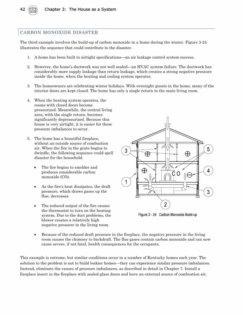
CARBON MONOXIDE DISASTER
The third example involves the build-up of carbon monoxide in a home during the winter. Figure 3-24 illustrates the sequence that could contribute to the disaster.
1. A home has been built to airtight specifications—an air leakage control system success.
2. However, the home’s ductwork was not well sealed—an HVAC system failure. The ductwork has considerably more supply leakage than return leakage, which creates a strong negative pressure inside the home, when the heating and cooling system operates.
3. The homeowners are celebrating winter holidays. With overnight guests in the home, many of the
interior doors are kept closed. The home has only a single return in the main living room.
4. When the heating system operates, the rooms with closed doors become pressurized. Meanwhile, the central living area, with the single return, becomes significantly depressurized. Because this house is very airtight, it is easier for these pressure imbalances to occur.
5. The home has a beautiful fireplace,
without an outside source of combustion air. When the fire in the grate begins to dwindle, the following sequence could spell disaster for the household.
The fire begins to smolder and
produces considerable carbon monoxide (CO).
As the fire’s heat dissipates, the draft
pressure, which draws gases up the flue, decreases.
The reduced output of the fire causes
the thermostat to turn on the heating system. Due to the duct problems, the blower creates a relatively high negative pressure in the living room.
Because of the reduced draft pressure in the fireplace, the negative pressure in the living
room causes the chimney to backdraft. The flue gases contain carbon monoxide and can now cause severe, if not fatal, health consequences for the occupants.
This example is extreme, but similar conditions occur in a number of Kentucky homes each year. The solution to the problem is not to build leakier homes—they can experience similar pressure imbalances. Instead, eliminate the causes of pressure imbalances, as described in detail in Chapter 7. Install a fireplace insert in the fireplace with sealed glass doors and have an external source of combustion air.