cip 2 - scaling concrete surfaces 2 - scaling concrete surfaces why do concrete surfaces scale...
TRANSCRIPT

Scaling is local flaking or peeling of a finished surface
of hardened concrete as a result of exposure to freez-
ing and thawing. Generally, it starts as localized small
patches which later may merge and extend to expose
large areas. Light scaling does not expose the coarse
aggregate. Moderate scaling exposes the aggregate and
may involve loss of up to 1/8 to 3/8 inch [3 to 10 mm] of
the surface mortar. In severe scaling more surface has
been lost and the aggregate is clearly exposed and
stands out.
Note—Occasionally concrete peels or scales in the absence of freez-
ing and thawing. This type of scaling is not covered in this CIP.
Often this is due to the early use of a steel trowel, over-finishing or
finishing while bleed water is on the surface. (see CIP 20 on Delami-
nations)
Scaling concrete surface
WHAT is Scaling
HOW to Prevent Scaling
CIP 2 - Scaling Concrete Surfaces
WHY Do Concrete Surfaces Scale
Concrete slabs exposed to freezing and thawing in the
presence of moisture and/or deicing salts are suscep-
tible to scaling. Most scaling is caused by:
a. The use of non-air-entrained concrete or too
little entrained air. Adequate air entrainment is re-
quired for protection against freezing and thawing
damage. However, even air-entrained concrete will
scale if other precautions, as listed below, are not
observed.
b. Application of excessive amounts of calcium or so-
dium chloride deicing salts on concrete with inad-
equate strength, air entrainment, or curing. Chemi-
cals such as ammonium sulfate or ammonium ni-
trate, which are components of most fertilizers, can
cause scaling as well as induce severe chemical at-
tack on the concrete surface.
c. Any finishing operation performed while bleed wa-
ter is on the surface. If bleed water is worked back
into the top surface of the slab, a high water-cement
ratio and, therefore, a low-strength surface layer
is produced. Overworking the surface during
finishing will reduce the air content in the surface
layer, making it susceptible to scaling in freezing con-
ditions.
d. Insufficient curing. This omission often results in a
weak surface skin, which will scale if it is exposed
to freezing and thawing in the presence of moisture
and deicing salts.
a. Concrete exposed to freezing and thawing cycles
must be air-entrained. Severe exposures require air
contents of 6 to 7 percent in freshly mixed concrete
made with 3/4-inch [19 mm] or 1-inch [25-mm] aggre-
gate. In moderate exposures, where deicing salts will
not be used, 4 to 6 percent air will be sufficient. Air-
entrained concrete of moderate slump (up to 5 inches
[125 mm]) and adequate quality should be used. In
general, concrete strength of 3500 psi [24 MPa] for
freezing and thawing exposure and 4000 psi [28
MPa] when deicers are used should be adequate to
prevent scaling.
b. DO NOT use deicing salts, such as calcium or so-
dium chloride, in the first year after placing the con-
crete. Use clean sand for traction. When condi-
tions permit, hose off accumulation of salt deposited
by cars on newly placed driveways and garage slabs.
Subsequently, use salt sparingly. Never use ammo-
HOW to Prevent Scaled Surfaces
1978, 1989, 1990 AND 1998
nium sulfate or ammonium nitrate as a deicer;
these are chemically aggressive and destroy con-
crete surfaces. Poor drainage, which permits water
or salt and water to stand on the surface for ex-
tended periods of time, greatly increases the sever-
ity of the exposure and may cause scaling. (This is
often noticed in gutters and sidewalks where the
snow from plowing keeps the surface wet for long
periods of time.)
c. Provide proper curing by using liquid membrane cur-
ing compound or by covering the surface of newly
placed slab with wet burlap. Curing ensures the
proper reaction of cement with water, known as hy-
dration, which allows the concrete to achieve its high-
est potential strength.
d. DO NOT perform any finishing operations with
water present on the surface. Bull floating must
promptly follow initial screeding. Delay finishing
operations until all the bleed water has risen to and
disappeared from the surface. This is critical with
air-entrained concrete in dry and windy conditions
where concrete that is continuing to bleed may ap-
pear dry on the surface.
e. Do not use a jitterbug or vibrating screed with high
slump concrete, as it tends to form a weak layer of
mortar on the surface.
f. Protect concrete from the harsh winter environment.
It is important to prevent the newly placed concrete
from becoming saturated with water prior to freeze
and thaw cycles during winter months. Apply a com-
mercially available silane or siloxane-based breath-
able concrete sealer or water repellent specifically
designed for use on concrete slabs. Follow the
manufacturer’s recommendations for application
procedures and frequency. Another option is a 1:1
mixture of boiled linseed oil and mineral spirits ap-
The repaired surface will only be as strong as the base
surface to which it is bonded. Therefore, the surface to
be repaired should be free of dirt, oil or paint and, most
importantly, it must be sound. To accomplish this, use a
hammer and chisel, sandblasting, high-pressure washer,
or jack hammer to remove all weak or unsound mate-
rial. The clean, rough, textured surface is then ready
for a thin bonded resurfacing such as:
a. Portland cement concrete resurfacing
b. Latex modified concrete resurfacing
c. Polymer-modified cementitious-based repair mortar
References
1. Guide to Durable Concrete, ACI 201.2R, American
Concrete Institute, Farmington Hills, MI.
2. Scale-Resistant Concrete Pavements, IS117.02P, Portland
Cement Association, Skokie, IL.
3. Protective Coatings to Prevent Deterioration of Concrete by
Deicing Chemicals, National Cooperative Highway Research
Program Report No. 16.
4. Guide for Concrete Floor and Slab Construction, ACI 302.1R,
American Concrete Institute, Farmington Hills, MI.
5. Residential Concrete, National Association of Home Build-
ers, Washington, DC.
6. Slabs on Grade, Concrete Craftsman Series CCS-1, Ameri-
can Concrete Institute, Farmington Hills, MI.
7. Eugene Goeb, Deicer Scaling: An Unnecessary Problem,
Concrete Products, February 1994.
plied in two layers. The concrete should be reason-
ably dry prior to the application of a sealer. Late
summer is the ideal time for surface treatment. The
sealer can be sprayed, brushed, or rolled on the sur-
face of the concrete. CAUTION: Linseed oil will
darken the color of the concrete and care should be
taken to apply it uniformly.
Follow These Rules to Prevent Scaling
1. For moderate to severe exposures, use air-entrained concrete of medium slump (3-5 in. [75-125 mm])
and cure properly.
2. Do not use deicers in the first winter.
3. Seal the surface with a commercial sealer or a mixture of boiled linseed oil and mineral spirits.
4. Use correct timing for all finishing operations and avoid the use of steel trowels for exterior concrete slabs.
5. Specify air-entrained concrete. In cold weather, concrete temperature should be at least 50°F [10°C],
contain an accelerating admixture, and be placed at a lower slump.

CIP 3 - Crazing Concrete Surfaces
WHY Do Concrete Surfaces Craze?
WHAT is Crazing?
Crazing is the development of a network of fine ran-
dom cracks or fissures on the surface of concrete or
mortar caused by shrinkage of the surface layer. These
cracks are rarely more than 1/8 inch [3 mm] deep and
are more noticeable on steel-troweled surfaces. The
irregular hexagonal areas enclosed by the cracks are
typically no more than 11/2 inch [40 mm] across and
may be as small as 1/2 or 3/8 inch [12 or 20 mm] in
unusual instances. Generally, craze cracks develop at
an early age and are apparent the day after placement
or at least by the end of the first week. Often they are
not readily visible until the surface has been wetted
and it is beginning to dry out.
Crazing cracks are sometimes referred to as shallow
map or pattern cracking. They do not affect the
structural integrity of concrete and rarely do they
affect durability or wear resistance. However, crazed
surfaces can be unsightly. They are particularly con-
spicuous and unsightly when concrete contains calcium
chloride, a commonly used accelerating admixture.
Concrete surface crazing usually occurs because one
or more of the rules of “good concrete practices” were
not followed. The most frequent violations are:
a. Poor or inadequate curing. Environmental conditions
conducive to high evaporation rates, such as low
humidity, high temperature, direct sunlight, and dry-
ing winds on a concrete surface when the concrete
is just beginning to gain strength, cause rapid sur-
face drying resulting in craze cracking. Avoid the
delayed application of curing or even intermittent
wet curing and drying after the concrete has been
finished.
b. Too wet a mix, excessive floating, the use of a jitter-
bug or any other procedures that will depress the
coarse aggregate and produce an excessive con-
centration of cement paste and fines at the surface.
c. Finishing while there is bleed water on the surface
or the use of a steel trowel at a time when the smooth
surface of the trowel brings up too much water and
cement fines. Use of a bull float or darby with wa-
ter on the surface or while the concrete continues
to bleed will produce a high water-cement ratio, weak
surface layer which will be susceptible to crazing,
dusting and other surface defects.
d. Sprinkling cement on the surface to dry up the bleed
water is a frequent cause of crazing. This concen-
trates fines on the surface. Spraying water on the
concrete surface during finishing operations will re-
sult in a weak surface susceptible to crazing or dust-
ing.
e. Occasionally carbonation of the surface results in
crazing as it causes shrinkage of the surface layer.
Carbonation is a chemical reaction between cement
and carbon dioxide or carbon monoxide from
unvented heaters. In such instances the surface
will be soft and will dust as well.
Crazing Concrete Surface (Dampened)

1978, 1989 AND 1998
HOW to Prevent Crazing?
a. To prevent crazing, start curing the concrete as soon
as possible. Keep the surface wet by either flood-
ing with water, covering it with damp burlap and
keeping it continuously moist for a minimum of 3
days, or spraying the surface with a liquid-mem-
brane curing compound. Avoid alternate wetting
and drying of concrete surfaces at an early age.
Curing retains the moisture required for proper re-
action of cement with water, called hydration.
b. Use moderate slump (3 to 5 inches [75 to 125 mm])
concrete. Higher slump (up to 6 or 7 inches [150 to
175 mm]) can be used provided the mixture is de-
signed to produce the required strength without ex-
cessive bleeding and/or segregation. This is gener-
ally accomplished by using water-reducing admix-
tures.
c. NEVER sprinkle or trowel dry cement or a mixture
of cement and fine sand on the surface of the plas-
tic concrete to absorb bleed water. DO NOT
sprinkle water on the slab to facilitate finishing. Re-
move bleed water by dragging a garden hose across
the surface. DO NOT perform any finishing opera-
tion while bleed water is present on the surface or
before the bleeding process is completed. DO NOT
overwork or over-finish the surface.
d. When high evaporation rates are possible, lightly
dampen the subgrade prior to concrete placement
to prevent it absorbing too much water from the con-
crete. If a vapor retarder is required on the subgrade,
cover it with 3 to 4 inches of a compactible, granu-
lar fill, such as a crusher-run material to reduce bleed-
ing.
References
1. Guide for Concrete Floor and Slab Construction, ACI
302.1R, American Concrete Institute, Farmington Hills,
MI.
2. Concrete Slab Surface Defects: Causes, Prevention,
Repair, IS 177T, Portland Cement Association, Skokie,
IL.
3. Ward Malisch, Avoiding Common Outdoor Flatwork
Problems, Concrete Construction, July 1990.
4. Ralph Spannenberg, Use the Right Tool at the Right Time,
Concrete Construction, May 1996.
Follow These Rules to Prevent Crazing
1. Use moderate slump (3-5 inches) concrete with reduced bleeding characteristics.
2. Follow recommended practices and timing, based on concrete setting characteristics, for placing and
finishing operations:
a. Avoid excessive manipulation of the surface, which can depress the coarse aggregate, increase the
cement paste at the surface, or increase the water-cement ratio at the surface.
b. DO NOT finish concrete before the concrete has completed bleeding. DO NOT dust any cement onto
the surface to absorb bleed water. DO NOT sprinkle water on the surface while finishing concrete.
c. When steel troweling is required, delay it until the water sheen has disappeared from the surface.
3. Cure properly as soon as finishing has been completed.
CIP 5 - Plastic Shrinkage Cracking
WHAT is Plastic Shrinkage Cracking?
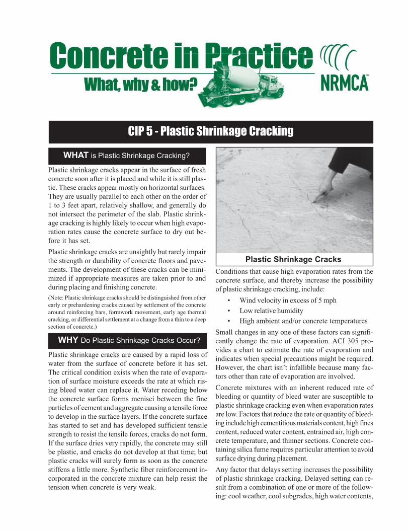
Plastic shrinkage cracks appear in the surface of fresh
concrete soon after it is placed and while it is still plas-
tic. These cracks appear mostly on horizontal surfaces.
They are usually parallel to each other on the order of
1 to 3 feet apart, relatively shallow, and generally do
not intersect the perimeter of the slab. Plastic shrink-
age cracking is highly likely to occur when high evapo-
ration rates cause the concrete surface to dry out be-
fore it has set.
Plastic shrinkage cracks are unsightly but rarely impair
the strength or durability of concrete floors and pave-
ments. The development of these cracks can be mini-
mized if appropriate measures are taken prior to and
during placing and finishing concrete.
(Note: Plastic shrinkage cracks should be distinguished from other
early or prehardening cracks caused by settlement of the concrete
around reinforcing bars, formwork movement, early age thermal
cracking, or differential settlement at a change from a thin to a deep
section of concrete.)
Plastic Shrinkage Cracks
Plastic shrinkage cracks are caused by a rapid loss of
water from the surface of concrete before it has set.
The critical condition exists when the rate of evapora-
tion of surface moisture exceeds the rate at which ris-
ing bleed water can replace it. Water receding below
the concrete surface forms menisci between the fine
particles of cement and aggregate causing a tensile force
to develop in the surface layers. If the concrete surface
has started to set and has developed sufficient tensile
strength to resist the tensile forces, cracks do not form.
If the surface dries very rapidly, the concrete may still
be plastic, and cracks do not develop at that time; but
plastic cracks will surely form as soon as the concrete
stiffens a little more. Synthetic fiber reinforcement in-
corporated in the concrete mixture can help resist the
tension when concrete is very weak.
WHY Do Plastic Shrinkage Cracks Occur?
Conditions that cause high evaporation rates from the
concrete surface, and thereby increase the possibility
of plastic shrinkage cracking, include:
• Wind velocity in excess of 5 mph
• Low relative humidity
• High ambient and/or concrete temperatures
Small changes in any one of these factors can signifi-
cantly change the rate of evaporation. ACI 305 pro-
vides a chart to estimate the rate of evaporation and
indicates when special precautions might be required.
However, the chart isn’t infallible because many fac-
tors other than rate of evaporation are involved.
Concrete mixtures with an inherent reduced rate of
bleeding or quantity of bleed water are susceptible to
plastic shrinkage cracking even when evaporation rates
are low. Factors that reduce the rate or quantity of bleed-
ing include high cementitious materials content, high fines
content, reduced water content, entrained air, high con-
crete temperature, and thinner sections. Concrete con-
taining silica fume requires particular attention to avoid
surface drying during placement.
Any factor that delays setting increases the possibility
of plastic shrinkage cracking. Delayed setting can re-
sult from a combination of one or more of the follow-
ing: cool weather, cool subgrades, high water contents,

1978, 1992 AND 1998
Follow These Rules to Minimize Plastic Shrinkage Cracking
1. Dampen the subgrade and forms when conditions for high evaporation rates exist.
2. Prevent excessive surface moisture evaporation by providing fog sprays and erecting windbreaks.
3. Cover concrete with wet burlap or polyethylene sheets between finishing operations.
4. Use cooler concrete in hot weather and avoid excessively high concrete temperatures in cold weather.
5. Cure properly as soon as finishing has been completed.
lower cement contents, retarders, some water reduc-
ers, and supplementary cementing materials.
Attempts to eliminate plastic shrinkage cracking by
modifying the composition to affect bleeding charac-
teristics of a concrete mixture have not been found to
be consistently effective. To reduce the potential for
plastic shrinkage cracking, it is important to recog-
nize ahead of time, before placement, when weather
conditions conducive to plastic shrinkage cracking
will exist. Precautions can then be taken to mini-
mize its occurrence.
a. When adverse conditions exist, erect temporary wind-
breaks to reduce the wind velocity over the surface of
the concrete and, if possible, provide sunshades to con-
trol the surface temperature of the slab. If conditions
are critical, schedule placement to begin in the later
afternoon or early evening. However, in very hot con-
ditions, early morning placement can afford better con-
trol on concrete temperatures.
b. In the very hot and dry periods, use fog sprays to
discharge a fine mist upwind and into the air above
the concrete. Fog sprays reduce the rate of evapo-
ration from the concrete surface and should be con-
tinued until suitable curing materials can be applied.
c. If concrete is to be placed on a dry absorptive
subgrade in hot and dry weather, dampen the
subgrade but not to a point that there is freestand-
ing water prior to placement. The formwork and
reinforcement should also be dampened.
d. The use of vapor retarders under a slab on grade
greatly increases the risk of plastic shrinkage crack-
ing. If a vapor retarder is required, cover it with a 3 to
4 inch lightly dampened layer of a trimable, compact-
ible granular fill, such as a crusher-run material.
e. Have proper manpower, equipment, and supplies
on hand so that the concrete can be placed and
finished promptly. If delays occur, cover the con-
crete with moisture-retaining coverings, such as wet
burlap, polyethylene sheeting or building paper, be-
tween finishing operations. Some contractors find
that plastic shrinkage cracks can be prevented in
hot dry climates by spraying an evaporation re-
tardant on the surface behind the screeding op-
eration and following floating or troweling, as
needed, until curing is started.
f. Start curing the concrete as soon as possible. Spray
the surface with liquid membrane curing compound
or cover the surface with wet burlap and keep it
continuously moist for a minimum of 3 days.
g. Consider using synthetic fibers (ASTM C 1116) to
resist plastic shrinkage cracking.
h. Accelerate the setting time of concrete and avoid
large temperature differences between concrete
and air temperatures.
If plastic shrinkage cracks should appear during final fin-
ishing, the finisher may be able to close them by refinish-
ing. However, when this occurs precautions, as discussed
above, should be taken to avoid further cracking.
HOW to Minimize Plastic Shrinkage Cracking?
References
1. Hot Weather Concreting, ACI 305R, American Concrete In-
stitute, Farmington Hills, MI.
2. Guide for Concrete Floor and Slab Construction, ACI 302.1R,
American Concrete Institute, Farmington Hills, MI.
3. Standard Practice for Curing Concrete, ACI 308, American
Concrete Institute, Farmington Hills, MI.
4. Concrete Slab Surface Defects: Causes, Prevention, Repair,
IS177, Portland Cement Association, Skokie, IL.
5. Bruce A. Suprenant, Curing During the Pour, Concrete Con-
struction, June 1997.
6. Eugene Goeb, Common Field Problems, Concrete Construc-
tion, October 1985.

CIP 6 - Joints in Concrete Slabs on Grade
WHAT are Joints?
WHY are Joints Constructed?
Concrete expands and shrinks with changes in mois-
ture and temperature. The overall tendency is to shrink
and this can cause cracking at an early age. Irregular
cracks are unsightly and difficult to maintain but gen-
erally do not affect the integrity of concrete. Joints are
simply pre-planned cracks. Joints in concrete slabs can
be created by forming, tooling, sawing, and placement
of joint formers.
Some forms of joints are:
a. Contraction joints – are intended to create weak-
ened planes in the concrete and regulate the loca-
tion where cracks, resulting from dimensional
changes, will occur.
b. Isolation or expansion joints – separate or isolate
slabs from other parts of the structure, such as walls,
footings, or columns; and driveways and patios from
sidewalks, garage slabs, stairs, lightpoles and other
points of restraint. They permit independent verti-
cal and horizontal movement between adjoining parts
of the structure and help minimize cracking when
such movements are restrained.
c. Construction joints – are surfaces where two suc-
cessive placements of concrete meet. They are typi-
cally placed at the end of a day’s work but may be
required when concrete placement is stopped for
longer than the initial setting time of concrete. In
slabs they may be designed to permit movement
and/or to transfer load. The location of construction
joints should be planned. It may be desirable to
achieve bond and continue reinforcement through a
construction joint.
Cracks in concrete cannot be prevented entirely, but
they can be controlled and minimized by properly de-
signed joints. Concrete cracks because:
a. Concrete is weak in tension and, therefore, if its
natural tendency to shrink is restrained, tensile
stresses that exceed its tensile strength can develop,
resulting in cracking.
b. At early ages, before the concrete dries out, most
cracking is caused by temperature changes or by
the slight contraction that takes place as the con-
crete sets and hardens. Later, as the concrete dries,
it will shrink further and either additional cracks may
form or preexisting cracks may become wider.
Joints provide relief from the tensile stresses, are easy
to maintain and are less objectionable than uncontrolled
or irregular cracks.
How to Construct Joints?
Joints must be carefully designed and properly con-
structed if uncontrolled cracking of concrete flatwork
is to be avoided. The following recommended prac-
tices should be observed:
a. The maximum joint spacing should be 24 to 36 times
the thickness of the slab. For example, in a 4-inch
[100 mm] thick slab the joint spacing should be about
Saw cut Tooled
Wall or Column
Expansion joint material
Slab on grade
Column
Contraction jointsintersect at diagonals
of the square
Form openingswhich
will be filled afterfloor has hardened
Concrete cracks below joints
Slab isolated from footing
Keyed Doweled
Contraction Joints
Isolation Joints
Construction Joints

1979, 1989 AND 1998
Follow These Rules for Proper Jointing
1. Plan exact location of all joints, including timing of contraction joint sawing before construction.
2. Provide isolation joints between slabs and columns, walls and footings, and at junctions of driveways with
walks, curbs or other obstructions.
3. Provide contraction joints and joint filling materials as outlined in specifications.
References
1. Joints in Concrete Construction, ACI 224.3R, American
Concrete Institute, Farmington Hills, MI.
2. Guide for Concrete Floor and Slab Construction, ACI
302.1R, American Concrete Institute, Farmington Hills,
MI.
3. Slabs on Grade, ACI Concrete Craftsman Series CCS-1,
American Concrete Institute, Farmington Hills, Ml.
4. Joint Planning Primer, Concrete Construction, August
1997.
5. Bruce A. Suprenant, Sawcutting Joints in Concrete, Con-
crete Construction, January 1995.
10 feet [3 m]. It is further recommended that joint
spacing be limited to a maximum of 15 feet [4.5 m].
b. All panels should be square or nearly so. The length
should not exceed 1.5 times the width. Avoid
L-shaped panels.
c. For contraction joints, the joint groove should have
a minimum depth of 1/4 the thickness of the slab,
but not less than 1 inch [25 mm]. Timing of
jointing operations depends on the method used:
• Preformed plastic or hard board joint strips are
inserted into the concrete surface to the
required depth before finishing.
• Tooled joints must be run early in the finishing
process and rerun later to ensure groove bond
has not occurred.
• Early-entry dry-cut joints are generally run 1 to
4 hours after completion of finishing, depending
on the concrete’s setting characteristics. These
joints are typically not as deep as those ob-
tained by the conventional saw-cut process,
but should be a minimum of 1 inch [25 mm] in
depth.
• Conventional saw-cut joints should be run
within 4 to 12 hours after the concrete has
been finished.
d. Raveling during saw cutting is affected by the
strength of the concrete and aggregate character-
istics. If the joint edges ravel during sawing, it must
be delayed. However, if delayed too long, sawing
can become difficult and uncontrolled cracking may
occur.
e. Use premolded joint filler such as asphalt-impreg-
nated fiber sheeting, compressible foam strips, or
similar materials for isolation joints to separate slabs
from building walls or footings. At least 2 inches
[50 mm] of sand over the top of a footing will also
prevent bond to the footing.
f. To isolate columns from slabs, form circular or
square openings, which will not be filled until after
the floor has hardened. Slab contraction joints should
intersect at the openings for columns. If square open-
ings are used around columns, the square should be
turned at 45 degrees so the contraction joints inter-
sect at the diagonals of the square.
g. If the slab contains wire mesh, cut out alternate
wires, or preferably discontinue the mesh, across
contraction joints. Note that wire mesh will not pre-
vent cracking. Mesh tends to keep the cracks and
joints tightly closed.
h. Construction joints key the two edges of the slab
together either to provide transfer of loads or to help
prevent curling or warping of the two adjacent edges.
Galvanized metal keys are sometimes used for in-
terior slabs, however, a beveled 1 by 2 inch [25 by
50 mm] strip, nailed to bulkheads or form boards,
can be used in slabs that are at least 5 inches [125
mm] thick to form a key which will resist vertical
loads and movements. Keyed joints are not recom-
mended for industrial floors. Metal dowels should
be used in slabs that will carry heavy loads. Dowels
must be carefully lined up and parallel or they may
induce restraint and cause random cracking at the
end of the dowel.
i. Joints in industrial floors subject to heavy traffic re-
quire special attention to avoid spalling of joint edges.
Such joints should be filled with a material capable
of supporting joint edges. Manufacturer’s recom-
mendations and performance records should be
checked before use.

CIP 11 - Curing In-Place Concrete
WHAT is Curing?
WHY Cure?
Curing is the maintaining of an adequate moisture content
and temperature in concrete at early ages so that it can
develop properties the mixture was designed to achieve.
Curing begins immediately after placement and finishing so
that the concrete may develop the desired strength and du-rability.
Without an adequate supply of moisture, the cementitious
materials in concrete cannot react to form a quality product.
Drying may remove the water needed for this chemical reac-
tion called hydration and the concrete will not achieve its
potential properties.
Temperature is an important factor in proper curing, since
the rate of hydration, and therefore, strength development,
is faster at higher temperatures. Generally, concrete tem-
perature should be maintained above 50°F (10°C) for an ad-equate rate of strength development. Further, a uniform tem-
perature should be maintained through the concrete sec-
tion while it is gaining strength to avoid thermal cracking.
For exposed concrete, relative humidity and wind condi-
tions are also important; they contribute to the rate of mois-
ture loss from the concrete and could result in cracking,
poor surface quality and durability. Protective measures to
control evaporation of moisture from concrete surfaces be-
fore it sets are essential to prevent plastic shrinkage crack-
ing (See CIP 5).
Several important reasons are:
a. Predictable strength gain. Laboratory tests showthat concrete in a dry environment can lose as much as
50 percent of its potential strength compared to similar
concrete that is moist cured. Concrete placed under high
temperature conditions will gain early strength quickly
but later strengths may be reduced. Concrete placed in
cold weather will take longer to gain strength, delaying
form removal and subsequent construction.
b. Improved durability. Well-cured concrete has better
surface hardness and will better withstand surface wear
and abrasion. Curing also makes concrete more water-
tight, which prevents moisture and water-borne chemi-
cals from entering into the concrete, thereby increasingdurability and service life.
HOW to Cure?
Moisture Requirements for Curing:
Concrete should be protected from losing moisture until
final finishing using suitable methods like wind breaks,
fogger sprays or misters to avoid plastic shrinkage crack-
ing. After final finishing the concrete surface must be kept
continuously wet or sealed to prevent evaporation for a
period of at least several days after finishing. See the table
for examples.
Application of liquid membrane-forming compound
with hand sprayer.
Slab on grade covered with waterproof paper for curing.
c. Better serviceability and appearance. A concrete
slab that has been allowed to dry out too early will have
a soft surface with poor resistance to wear and abrasion.
Proper curing reduces crazing, dusting and scaling.
1982, 1989 AND 2000
Systems to keep concrete wet include:
a. Burlap or cotton mats and rugs used with a soaker hose
or sprinkler. Care must be taken not to let the coverings
dry out and absorb water from the concrete. The edges
should be lapped and the materials weighted down so
they are not blown away.
b. Straw that is sprinkled with water regularly. Straw can
easily blow away and, if it dries, can catch fire. The layer
of straw should be 6 inches thick, and should be covered
with a tarp.
c. Damp earth, sand, or sawdust can be used to cure flatwork,
especially floors. There should be no organic or iron-
staining contaminants in the materials used.
d. Sprinkling on a continuous basis is suitable provided the
air temperature is well above freezing. The concrete
should not be allowed to dry out between soakings, since
alternate wetting and drying is not an acceptable curing
practice.
e. Ponding of water on a slab is an excellent method of cur-
ing. The water should not be more than 20°F (11°C) coolerthan the concrete and the dike around the pond must be
secure against leaks.
Moisture retaining materials include:
a. Liquid membrane-forming curing compounds must con-
form to ASTM C 309. Apply to the concrete surface about
one hour after finishing. Do not apply to concrete that is
still bleeding or has a visible water sheen on the surface.
While a clear liquid may be used, a white pigment will
provide reflective properties and allow for a visual in-
spection of coverage. A single coat may be adequate, but
where possible a second coat, applied at right angles to
the first, is desirable for even coverage. If the concretewill be painted, or covered with vinyl or ceramic tile, then
a liquid compound that is non-reactive with the paint or
adhesives must be used, or use a compound that is eas-
ily brushed or washed off. On floors, the surface should
be protected from the other trades with scuff-proof paper
after the application of the curing compound.
b. Plastic sheets - either clear, white (reflective) or pig-
mented. Plastic should conform to ASTM C 171, be at
least 4 mils thick, and preferably reinforced with glass
fibers. Dark colored sheets are recommended when ambi-
ent temperatures are below 60°F (15°C) and reflective
sheets should be used when temperatures exceed 85°F
(30°C). The plastic should be laid in direct contact withthe concrete surface as soon as possible without marring
the surface. The edges of the sheets should overlap and
be fastened with waterproof tape and then weighted down
to prevent the wind from getting under the plastic. Plas-
tic can make dark streaks wherever a wrinkle touches the
concrete, so plastic should not be used on concretes
where appearance is important. Plastic is sometimes used
over wet burlap to retain moisture.
c. Waterproof paper - used like plastic sheeting, but does
not mar the surface. This paper generally consists of two
Example Minimum Curing Period
to Achieve 50% of Specified Strength*
Type I Type II Type III
Cement Cement Cement
Temperature—50°F (10°C)
6 days 9 days 3 days
Temperature—70°F (21°C)
4 days 6 days 3 days
*Values are approximate and based on cylinder strength
tests. Specific values can be established for specific
materials and mixtures. From Ref. 7.
layers of kraft paper cemented together and reinforced
with fiber. The paper should conform to ASTM C 171.
Note that products sold as evaporation retardants are used
to reduce the rate of evaporation from fresh concrete sur-
faces before it sets to prevent plastic shrinkage cracking.These materials should not be used for final curing.
Control of temperature:
In cold weather do not allow concrete to cool faster than a
rate of 5°F (3°C) per hour for the first 24 hours. Concrete
should be protected from freezing until it reaches a com-
pressive strength of at least 500 psi (3.5 MPa) using insulat-
ing materials. Curing methods that retain moisture, rather
than wet curing, should be used when freezing tempera-
tures are anticipated. Guard against rapid temperature
changes after removing protective measures. Guidelines are
provided in Reference 7.
In hot weather, higher initial curing temperature will result in
rapid strength gain and lower ultimate strengths. Water cur-ing and sprinkling can be used to achieve lower curing tem-
peratures in summer. Day and night temperature extremes
that allow cooling faster than 5°F (3°C) per hour during the
first 24 hours should be protected against.
References
1. Effect of Curing Condition on Compressive Strength of Con-
crete Test Specimens, NRMCA Publication No. 53, National
Ready Mixed Concrete Association, Silver Spring, MD.
2. How to Eliminate Scaling, Concrete International, February
1980. American Concrete Institute, Farmington Hills, MI.
3. ASTM C 309, Specification for Liquid Membrane Forming
Compounds for Curing Concrete, American Society for Test-
ing Materials, West Conshohocken, PA.
4. ASTM C 171, Specification for Sheet Materials for Curing
Concrete, American Society for Testing Materials, West
Conshohocken, PA.
5. Standard Practice for Curing Concrete, ACI 308, American
Concrete Institute, Farmington Hills, MI.
6. Standard Specification for Curing Concrete, ACI 308.1, Ameri-
can Concrete Institute, Farmington Hills, MI.
7. Cold Weather Concreting, ACI 306R, American Concrete In-
stitute, Farmington Hills, MI.

CIP 12 - Hot Weather Concreting
WHAT is Hot Weather?
WHY Consider Hot Weather?
Hot weather may be defined as any period of high
temperature in which special precautions need to be
taken to ensure proper handling, placing, finishing and
curing of concrete. Hot weather problems are most
frequently encountered in the summer, but the associ-
ated climatic factors of high winds, low relative hu-
midity and solar radiation can occur at any time, es-
pecially in arid or tropical climates. Hot weather con-
ditions can produce a rapid rate of evaporation of
moisture from the surface of the concrete and accel-
erated setting time, among other problems. Generally,
high relative humidity tends to reduce the effects of
high temperature.
It is important that hot weather be taken into account
when planning concrete projects because of the po-
tential effects on fresh and recently placed concrete.
High temperatures alone cause increased water de-
mand, which, in turn, will raise the water-cement ratio
and result in lower potential strength. Higher tempera-
tures tend to accelerate slump loss and can cause loss
of entrained air. Temperature also has a major effect
on the setting time of concrete: concrete placed under
high temperatures will set quicker and can, therefore,
require more rapid finishing. Concrete that is cured at
high temperatures at an early age will not be as strong
at 28 days as the same concrete cured at tempera-
tures in the range of 70°F (20°C).
High temperatures, high wind velocity, and low rela-
tive humidity can affect fresh concrete in two impor-
tant ways: the high rate of evaporation may induce
early plastic shrinkage or drying shrinkage cracking,
and the evaporation rate can remove surface water
HOW to Concrete in Hot Weather?
The key to successful hot weather concreting is:
1. recognition of the factors that affect concrete; and
2. planning to minimize their effects.
Use proven local recommendations for adjusting con-
crete proportions, such as the use of water reducing
necessary for hydration unless proper curing methods
are employed. Thermal cracking may result from rapid
drops in the temperature of the concrete, such as when
concrete stabs or walls are placed on a hot day fol-
lowed by a cool night. High temperature also acceler-
ates cement hydration and contributes to the potential
for thermal cracking in massive concrete structures.
Effect of temperature on water requirement of concrete (Ref. 1)
Effect of temperature on concrete setting time (Ref. 1)
250
260
270
280
290
300
310
30 50 70 90 110
Concrete Temperature, °FW
ate
r co
nte
nt, lb
/cu
.yd
.
3-in (75-mm) slump
1 1/2-in. (38-mm) aggregate
0
2
4
6
8
10
12
14
40 60 80 100 120
Concrete Temperature, °F
Initia
l S
et,
hr.

1982, 1989 AND 2000
and set retarding admixtures. Modifying the mixture
to reduce the heat generated by cement hydration,
such as the use of an ASTM Type II moderate heat
cement and the use of pozzolans and slag can reduce
potential problems with high concrete temperature. Ad-
vance timing and scheduling to avoid delays in deliv-
ery, placing and finishing is essential. Trucks should
be able to discharge immediately and adequate per-
sonnel should be available to place and handle the
concrete. When possible, deliveries should be sched-
uled to avoid the hottest part of the day. Limits on
maximum concrete temperature may be waived by
the purchaser if the concrete consistency is adequate
for the placement and excessive water addition is not
required.
In the case of extreme temperature conditions or with
mass concrete, the concrete temperature can be low-
ered by using chilled water or ice as part of the mixing
water. The ready mixed concrete producer uses other
measures, such as sprinkling and shading the aggre-
gate prior to mixing, to help lower the temperature of
the concrete.
If low humidity and high winds are predicted, wind-
breaks, sunscreens, mist fogging, or evaporation re-
tardants may be needed to avoid plastic shrinkage
cracking in slabs.
Follow These Rules for Hot Weather Concrete
1. Modify concrete mix designs as appropriate. Retarders, moderate heat of hydration cement, pozzolanic
materials, slag, or other proven local solutions may be used. Reduce the cement content of the mixture
as much as possible, while ensuring the concrete strength will be attained.
2. Have adequate manpower to quickly place, finish and cure the concrete.
3. Limit the addition of water at the job site—add water only on arrival at the job site to adjust the slump.
Water addition should not exceed about 2 to 21/2 gallons per cubic yard (10 to 12 L/m3). Adding water to
concrete that is more than 11/2 hours old should be avoided.
4. Slabs on grade should not be placed directly on polyethylene sheeting or other vapor retarders. Cover the
vapor retarder with a minimum 4-inch (100 mm) layer of compactible, easy-to-trim, granular fill material.
5. On dry and/or hot days, when conditions are conducive for plastic shrinkage cracking, dampen the
subgrade, forms and reinforcement prior to placing concrete, but do not allow excessive water to pond.
6. Begin final finishing operations as soon as the water sheen has left the surface; start curing as soon as
finishing is completed. Continue curing for at least 3 days; cover the concrete with wet burlap and plastic
sheeting to prevent evaporation or use a liquid membrane curing compound, or cure slabs with water (See
CIP 11). Using white pigmented membrane curing compounds will help by indicating proper coverage and
reflecting heat away from the concrete surface.
7. Protect test cylinders at the jobsite by shading and preventing evaporation. Field curing boxes with ice or
refrigeration may be used to ensure maintaining the required 60 to 80°F (17 to 27°C) for initial curing of
cylinders. (See CIP 9)
8. Do not use accelerators unless it is common practice to avoid plastic shrinkage cracking and expedite
finishing operations.
References
1. Hot Weather Concreting, ACI 305R, American Concrete
Institute, Farmington Hills, MI.
2. Cooling Ready Mixed Concrete, NRMCA Publication
No. 106, NRMCA, Silver Spring, MD.
3. Effect of Temperature and Delivery Time on Concrete
Proportions, R.D. Gaynor, R.C. Meininger, T.S. Khan,
NRMCA Publication 171, NRMCA, Silver Spring, MD.
4. Hot-Weather Concreting, Chapter 11 in Design and Con-
trol of Concrete Mixtures, Portland Cement Association,
Skokie, IL.
5. Keeping Concrete Cool in the Heat of Summer, K.C.
Hover, Concrete Construction, June 1993.

CIP 13 - Concrete Blisters
WHAT are Blisters?
Blisters are hollow, low-profile bumps on the concrete
surface, typically from the size of a dime up to 1 inch
(25 mm), but occasionally even 2 or 3 inches (50 – 75
mm) in diameter. A dense troweled skin of mortar
about 1/8in. (3 mm) thick covers an underlying void
that moves around under the surface during troweling.
Blisters may occur shortly after the completion of fin-
ishing operation. In poorly lighted areas, small blisters
may be difficult to see during finishing and may not be
detected until they break under traffic.
Blisters may form on the surface of fresh concrete
when either bubbles of entrapped air or bleed water
migrate through the concrete and become trapped un-
der the surface, which has been sealed prematurely
during the finishing operations. These defects are not
easily repaired after concrete hardens.
Blisters are more likely to form if:
1. Insufficient or excessive vibration is employed.
Insufficient vibration prevents the entrapped air
from being released and excessive use of vibrat-
ing screeds works up a thick mortar layer on the
surface.
2. An improper tool is used for floating the surface
or it is used improperly. The surface should be
tested to determine which tool, whether it be wood
or magnesium bull float, does not seal the surface.
The floating tool should be kept as flat as possible.
3. Excessive evaporation of bleed water occurs and
the concrete appears ready for final finishing op-
erations (premature finishing), when, in fact, the
underlying concrete is still releasing bleed water
and entrapped air. High rate of bleed water evapo-
ration is especially a problem during periods of high
ambient temperatures, high winds and/or low hu-
midity.
DENSE TROWELED SURFACE
AIR AND BLEED WATER
Concrete Blister
4. Entrained air is used or is higher than normal. Rate
of bleeding and quantity of bleed water is greatly
reduced in air-entrained concrete giving the ap-
pearance that the concrete is ready to float and
further finish causing premature finishing.
5. The subgrade is cooler than concrete. The top
surface sets faster than the concrete in the bot-
tom and the surface appears ready to be floated
and further finished.
6. The slab is thick and it takes a longer time for the
entrapped air and bleed water to rise to the sur-
face.
7. The concrete is cohesive or sticky from higher
content of cementitious materials or excessive fines
in the sand. These mixtures also bleed less and at
a slower rate. Concrete mixtures with lower con-
tents of cementitious materials bleed rapidly for a
WHY do Blisters Form?

1983, 2001, 2005
The finisher should be wary of a concrete surface that
appears to be ready for final finishing before it would
normally be expected. Emphasis in finishing opera-
tions should be on placing, striking off and bull floating
the concrete as rapidly as possible and without work-
ing up a layer of mortar on the surface. After these
operations are completed, further finishing should be
delayed as long as possible and the surface covered
with polyethylene or otherwise protected from evapo-
ration. If conditions for high evaporation rates exist,
place a cover on a small portion of the slab to judge if
the concrete is still bleeding. In initial floating, the float
blades should be flat to avoid densifying the surface
too early. Use of an accelerating admixture or heated
concrete often prevents blisters in cool weather. It is
recommended that non-air entrained concrete be used
in interior slabs and that air entrained concrete not be
steel troweled.
If blisters are forming, try to either flatten the trowel
blades or tear the surface with a wood float and delay
finishing as long as possible. Under conditions causing
rapid evaporation, slow evaporation by using wind
breaks, water misting of the surface, evaporation re-
tarders, or a cover (polyethylene film or wet burlap)
between finishing operations. Further recommenda-
tions are given in ACI 302.1R and ACI 305.
shorter period, have higher total bleeding and tend
to delay finishing.
8. A dry shake is prematurely applied, particularly
over air-entrained concrete.
9. The slab is placed directly on top of a vapor re-
tarder or an impervious base, preventing bleed
water from being absorbed by the subgrade.
HOW To Prevent Blisters?
References
1. Guide for Concrete Floor and Slab Construction, ACI
302.1R, American Concrete Institute, Farmington Hills,
MI. www.concrete.org
2. Slabs on Grade, ACI Concrete Craftsman Series, CCS
1, American Concrete Institute, Farmington Hills, MI.
3. Hot weather Concreting, ACI 305R, American Con
crete Institute, Farmington Hills, MI.
4. Concrete Slab Surface Defects: Causes,
Prevention,Repair, IS 177, Portland Cement Associa
tion, Skokie, IL. www.cement.org
5. Concrete Surface Blistering—Causes and Cures, Carl
O. Peterson, Concrete Construction, September 1970.
www.concreteconstruction.net
6. CIP 14 - Finishing Concrete Flatwork; CIP 20 -
Delamination of Troweled Concrete Surfaces, NRMCA
CIP Series. www.nrmca.org.
7. Finishing, Concrete Construction, August 1976, p. 369.
8. Finishing Problems and Surface Defects in Flatwork,
Concrete Construction, April 1979.
Follow These Rules to Avoid Blisters
1. Do not seal surface before air or bleed water from below have had a chance to escape.
2. Avoid dry shakes on air-entrained concrete.
3. Use heated or accelerated concrete to promote even setting throughout the depth of the slab in cooler
weather.
4. Do not place slabs directly on vapor retarders. If vapor retarders are essential (CIP 28) take steps to avoid
premature finishing.
5. Protect surface from premature drying and evaporation.
6. Do not use a jitterbug or excessive vibration such as a vibratory screed on slumps over 5 inches (125 mm).
7. Air entrained concrete should not be steel troweled. If required by specifications, extreme caution should be
exercised when timing the finishing operation.

CIP 19 - Curling of Concrete Slabs
WHAT is Curling?
Curling is the distortion of a slab into a curved shape
by upward or downward bending of the edges. The
occurrence is primarily due to differences in moisture
and/or temperature between the top and bottom sur-
faces of a concrete slab. The distortion can lift the
edges or the middle of the slab from the base, leaving
an unsupported portion. The slab section can crack
when loads exceeding its capacity are applied. Slab
edges might chip off or spall due to traffic when the
slab section curls upwards at its edges. In most cases,
curling is evident at an early age. Slabs may, however,
curl over an extended period.
Changes in slab dimensions that lead to curling are
most often related to moisture and temperature gradi-
ents in the slab. When one surface of the slab changes
size relative to the other, the slab will warp at its edges
in the direction of relative shortening. This curling is
most noticeable at the sides and corners. One pri-
mary characteristic of concrete that affects curling is
drying shrinkage. Anything that increases drying shrink-
age of concrete will tend to increase curling.
The most common occurrence of curling is when the
top surface of the slab dries and shrinks with respect
to the bottom. This causes an upward curling of the
edges of a slab (Figure 1A). Curling of a slab soon
after placement is most likely related to poor curing
and rapid surface drying. In slabs, excessive bleeding
due to high water content in the concrete or water
sprayed on the surface; or a lack of surface moisture
due to poor or inadequate curing can create increased
surface drying shrinkage relative to the bottom of the
slab. Bleeding is accentuated in slabs placed directly
on a vapor retarder (polyethylene sheeting) or when
topping mixtures are placed on concrete slabs. Shrink-
age differences from top to bottom in these cases are
larger than for slabs on an absorptive subgrade.
Thin slabs and long joint spacing tend to increase curl-
ing. For this reason, thin unbonded toppings need to
have a fairly close joint spacing.
In industrial floors, close joint spacing may be unde-
sirable because of the increased number of joints and
increased joint maintenance problems. However, this
must be balanced against the probability of interme-
diate random cracks and increased curling at the joints.
The other factor that can cause curling is temperature
differences between the top and bottom of the slab.
The top part of the slab exposed to the sun will ex-
pand relative to the cooler bottom causing a down-
ward curling of the edges (Figure 1B). Alternately,
during a cold night when the top surface cools and
contracts relative to the bottom surface in contact with
a warmer subgrade, the curling due to this tempera-
ture differential will add to the upward curling caused
by moisture differentials.
Slab Surface is
Cooler and Drier than Base
Slab Surface at a Higher Temperature
and Moisture than Base
A. Upward Curling – Typical in Internal Slabs
B. Downward Curling
Curling of Concrete Slabs
WHY do Concrete Slabs Curl?

1990, 2002, 2004
References
1. Guide for Concrete Floor and Slab Construction, ACI
302.1R American Concrete Institute, Farmington Hills,
MI www.concrete.org
2. Slabs on Grade, ACI Concrete Craftsman Series, CCS-
1 American Concrete Institute, Farmington Hills, MI.
3. Shrinkage and Curling of Slabs on Grade, Series in
three parts, R. F. Ytterberg, ACI Concrete International,
April, May and June 1987, American Concrete Insti-
tute.
4. Concrete Slab Surface Defects: Causes, Prevention,
Repair, IS177, Portland Cement Association, Skokie,
IL, www.cement.org
5. Pavement Design, Transportation Research Record
1207, National Research Council, Washington, D.C.,
1988, p. 44.
6. Controlling Curling and Cracking in Floors to Re-
ceive Coverings, J. Holland and W. Walker, Concrete
Construction, July 1998, www.worldofconcrete.com.
7. Where to Place the Vapor Retarder, B. Suprenant and
W. Malisch, Concrete Construction, May 1998.
8. Repairing Curled Slabs, B. Suprenant, Concrete Con-
struction, May 1999.
9. Residential Concrete, National Association of Home
Builders, Washington, DC, www.nahb.com.
HOW to Minimize Slab Curling?
The primary factors controlling dimensional changes
of concrete that lead to curling are drying shrinkage,
construction practices, moist or wet subgrades, and
day-night temperature cycles. The following practices
will help to minimize the potential for curling:
1. Use the lowest practical water content in the con-
crete.
2. Use the largest practical maximum size aggregate
and/or the highest practical coarse aggregate con-
tent to minimize drying shrinkage.
3. Take precautions to avoid excessive bleeding. In
dry conditions place concrete on a damp, but ab-
sorptive, subgrade so that all the bleed water is
not forced to the top of the slab. This may not be
appropiate for interior slabs on which a moisture
sensitive floor covering would be placed.
4. Avoid using polyethylene vapor retarders unless
covered with at least four inches (100 mm) of a
trimable, compactible granular fill (not sand). If a
moisture-sensitive floor covering will be placed
on interior slabs, the concrete will generally be
placed directly on a vapor retarder (see CIP29)
and other procedures may be necessary.
5. Avoid a higher than necessary cement content. Use
of pozzolan or slag is preferable to very high ce-
ment content.
6. Cure the concrete thoroughly, including joints and
edges. If membrane-curing compounds are used,
apply at twice the recommended rate in two ap-
plications at right angles to each other.
7. When minimizing curling is critical, use a joint spac-
ing not exceeding 24 times the thickness of the
slab.
8. For thin toppings, clean the base slab to ensure
bond and consider use of studs and wire around
the edges and particularly in the slab corners.
9. Use a thicker slab, or increase the thickness of
the slab at edges.
10.The use of properly designed and placed slab re-
inforcement may help reduce or eliminate curling.
Load transfer devices that minimize vertical move-
ment should be used across construction joints.
11.Certain types of breathable sealers or coatings on
slabs can work to minimize moisture differentials
and reduce curling.
When curling in a concrete slab application cannot be
tolerated alternate options include the use of shrink-
age reducing admixtures, shrinkage-compensating
concrete, post tensioned slab construction or vacuum
dewatering. These options should be decided before
the construction and could increase the initial cost of
the project.
Some methods of remedying slab curling include
ponding the slab to reduce curl followed by sawing
additional contraction joints, grinding slab joints where
curling has occurred to restore serviceability and in-
jecting a grout to fill voids under the slab to restore
support and prevent break-off of uplifted edges.
CIP 20 - Delamination of Troweled Concrete Surfaces
WHAT are Delaminations?
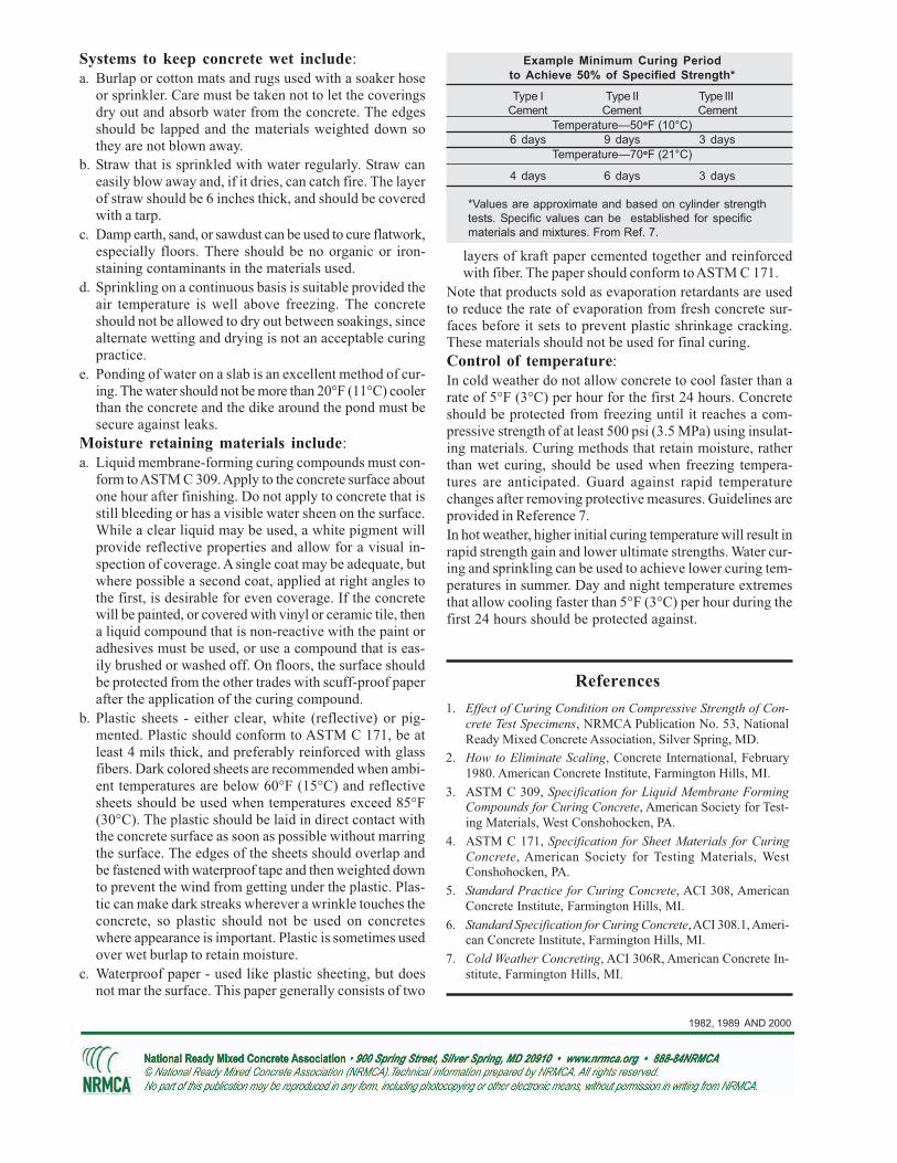
In most delaminated concrete slab surfaces, the top 1/
8 to ¼ inch (3 to 6 mm) is densified, primarily due to
premature and improper finishing, and separated fromthe base slab by a thin layer of air or water. The delami-nations on the surface of a slab may range in size fromseveral square inches to many square feet. The con-crete slab surface may exhibit cracking and color dif-ferences because of rapid drying of the thin surfaceduring curing. Traffic or freezing may break away thesurface in large sheets. Delaminations are similar toblisters, but much larger (see CIP 13).
Delaminations form during final troweling. They aremore frequent in early spring and late fall when con-crete is placed on a cool subgrade with rising daytimetemperatures, but they can occur at anytime depend-ing on the concrete characteristics and the finishingpractices used.
Corrosion of reinforcing steel near the concrete sur-face or poor bond between two-course placementsmay also cause delaminations (or spalling). The result-ing delaminations are generally thicker than thosecaused by improper finishing.
Delaminations are difficult to detect during finishingbut become evident after the concrete surface has setand dried. Delaminations can be detected by a hollowsound when tapped with a hammer or with a heavychain drag. A procedure is described in ASTM D 4580,Standard Practice for Measuring Delaminations inConcrete Bridge Decks by Sounding. More sophis-ticated techniques include acoustic impact echo andground-penetrating radar.
Bleeding is the upward flow of mixing water in plasticconcrete as a result of the settlement of the solids.Delamination occurs when the fresh concrete surface
is sealed or densified by troweling while the underlyingconcrete is still plastic and continues to bleed and/or torelease air. Delaminations form fairly late in the finish-ing process after floating and after the first troweling
pass. They can, however, form during the floating op-eration if the surface is overworked and densified. Thechances for delaminations are greatly increased whenconditions promote rapid drying of the surface (wind,sun, or low humidity). Drying and higher temperatureat the slab surface makes it appear ready to trowel
while the underlying concrete is plastic and can stillbleed or release air. Vapor retarders placed directlyunder slabs force bleed water to rise and compoundthe problem.
Factors that delay initial set of the concrete and re-duce the rate of bleeding will increase the chances fordelaminations. Entrained air in concrete reduces therate of bleeding and promotes early finishing that willproduce a dense impermeable surface layer. A coolsubgrade delays set in the bottom relative to the toplayer.
Delamination is more likely to form if:
1. The underlying concrete sets slowly because of acool subgrade.
2. The setting of the concrete is retarded due to con-
WHY does Delamination Occur?
Delaminated Concrete
DENSE TROWELED SURFACE
DELAMINATION ZONE
AIR AND BLEED WATER

1992, 2002, 2004
HOW to Prevent Delamination?
crete temperature or mixture ingredients.
3. The concrete has entrained air or the air content ishigher than desirable for the application.
4. The concrete mixture is sticky from highercementitious material or sand-fines content.
5. Environmental conditions during placement are con-ducive to rapid drying causing the surface to “crust”and appear ready to finish.
6. Concrete is excessively consolidated, such as theuse of a jitterbug or vibrating screed that brings
too much mortar to the surface.
7. A dry shake is used, particularly with air-entrainedconcrete.
8. The slab is thick.
9. The slab is placed directly on a vapor retarder.
Corrosion-related delaminations are formed when theupper layer of reinforcing steel rusts thereby breakingthe bond between the steel and the surrounding con-
crete. Corrosion of steel occurs with reduced concretecover and when the concrete is relatively more per-meable causing chlorides to penetrate to the layer ofthe steel (See CIP 25).
Follow These Rules to Avoid Delamination
1. Do not seal surface early—before air or bleed water from below have escaped.
2. Avoid dry shakes on air-entrained concrete.
3. Use heated or accelerated concrete to promote even setting throughout slab depth.
4. Avoid placing concrete directly on vapor retarders, if the application allows.
5. Do not use air-entrained concrete for interior slabs that will receive a trowel finish.
6. Avoid placing concrete on substrate with a temperature of less than 40° F (4° C).
References
1. Guide for Concrete Floor and Slab Construction, ACI 302.1R
American Concrete Institute, Farmington Hills, MI
www.concrete.org
2. Slabs on Grade, ACI Concrete Craftsman Series, American
Concrete Institute, Farmington Hills, MI.
3. Concrete Slab Surface Defects: Causes, Prevention, Repair,
IS177, Portland Cement Association, Skokie, IL,
www.cement.org
4. Diagnosing Slab Delaminations – Series in three parts, B.
Suprenant, Concrete Construction, January, February and
March 1998, www.worldofconcrete.com.
5. Using the Right Finishing Tool at the Right Time, R.H.
Spannenberg, Concrete Construction, May 1996.
6. Concrete in Practice Series, NRMCA, Silver Spring, Mary-
land, www.nrmca.org.
7. Residential Concrete, National Association of Home Build-
ers, Washington, DC, www.nahb.com.
8. ASTM D 4580, Annual Book of ASTM Standards, Vol 04.03,
ASTM International, West Conshohocken, PA,
www.astm.org.
Accelerators or heated concrete often prevent delami-nation in cool weather.
Be wary of a concrete surface that appears to be readyto trowel before it would normally be expected. Em-phasis in finishing should be on screeding, straight-edg-ing, and floating the concrete as rapidly as possible—without working up an excessive layer of mortar andwithout sealing the surface layer. In initial floating, thefloat blades should be flat to avoid densifying the sur-face too early.
Final finishing operations to produce a smooth surfaceshould be delayed as long as possible, and the surfacecovered with polyethylene or otherwise protected fromevaporation.
Delamination may be difficult to detect during finishingoperations. If delamination is observed, tear the sur-face with a wood float and delay finishing as long as
possible. Any steps that can be taken to slow evapora-tion should help.
If a vapor retarder is required, place at least four inches(100 mm) of a trimable, compactible granular fill (notsand). Do not place concrete directly on a vapor re-tarder. If a moisture-sensitive floor covering will beplaced on interior slabs, concrete will generally beplaced directly on a vapor retarder (see CIP 29), andother procedures may be necessary.
Do not use air-entrained concrete for interior floor slabsthat have a hard troweled surface and that will not besubject to freeze-thaw cycles or deicing salt applica-tion. If entrained air is necessary to protect interiorslabs from freezing and thawing cycles during con-struction avoid using air contents over 3%.
Delaminated surfaces can be repaired by patching af-ter the surface layer is removed and the underlayingconcrete is properly cleaned. Extensive delaminationmay need to be repaired by grinding and overlaying anew surface. Delaminated surfaces due to steel cor-rosion will additionally require sandblasting to removerust from the steel.

CIP 27 - Cold Weather Concreting
WHY Consider Cold Weather?
WHAT is Cold Weather?
Cold weather is defined as a period when the averagedaily temperature falls below 40°F [4°C] for more thanthree successive days. These conditions warrant spe-cial precautions when placing, finishing, curing andprotecting concrete against the effects of coldweather. Since weather conditions can change rap-idly in the winter months, good concrete practicesand proper planning are critical.
Successful cold-weather concreting requires an under-standing of the various factors that affect concrete prop-erties.
In its plastic state, concrete will freeze if its temperaturefalls below about 25°F [-4°C]. If plastic concrete freezes,its potential strength can be reduced by more than 50%and its durability will be adversely affected. Concreteshould be protected from freezing until it attains a mini-mum compressive strength of 500 psi [3.5 MPa], whichis about two days after placement for most concretemaintained at 50°F [10°C].
Low concrete temperature has a major effect on the rateof cement hydration, which results in slower setting andrate of strength gain. A good rule of thumb is that a dropin concrete temperature by 20°F [10°C] will approxi-mately double the setting time. The slower rate of set-ting and strength gain should be accounted for whenscheduling construction operations, such as form re-moval.
Concrete in contact with water and exposed to cyclesof freezing and thawing, even if only during construc-tion, should be air-entrained. Newly placed concrete issaturated with water and should be protected from cyclesof freezing and thawing until it has attained a compres-sive strength of at least 3500 psi [24.0 MPa].
Cement hydration is a chemical reaction that generatesheat. Newly placed concrete should be adequately insu-lated to retain this heat and thereby maintain favorablecuring temperatures. Large temperature differences be-tween the surface and the interior of the concrete massshould be prevented as cracking may result when thisdifference exceeds about 35°F [20°C]. Insulation or pro-tective measures should be gradually removed to avoidthermal shock.
Recommended concrete temperatures at the time of place-ment are shown below. The ready mixed concrete pro-ducer can control concrete temperature by heating themixing water and/or the aggregates and furnish concretein accordance with the guidelines in ASTM C 94.
Section Size, minimum Concrete temperaturedimension, inch [mm] as placed
less than 12 [300] 55°F [13°C]
12 - 36 [300 - 900] 50°F [10°C]
36 - 72 [900 - 1800] 45°F [7°C]
Cold weather concrete temperature should not exceedthese recommended temperatures by more than 20°F[10°C]. Concrete at a higher temperature requires moremixing water, has a higher rate of slump loss, and ismore susceptible to cracking. Placing concrete in coldweather provides the opportunity for better quality, ascooler initial concrete temperature will typically result inhigher ultimate strength.
Slower setting time and strength gain of concrete duringcold weather typically delays finishing operations and
HOW to Place Concrete in Cold Weather?
Figure 1 Effect of Temperature on Set Time (1a)
and Strength (1b) of Concrete
0
20
40
60
80
100
120
140
1 3 7 28 90 365Age, days
Com
pre
ssiv
e S
trength
, %
of 28-d
ay 7
3°F
73°F
55°F
40°F
1b
0
20
40
60
80
100
120
140
1 3 7 28 90 365Age, days
Com
pre
ssiv
e S
trength
, %
of 28-d
ay 7
3°F
73°F
55°F
40°F
1b
70 (21) 60 (16) 50 (10) 40 (4) 30 (-1) 20 (-7)
Concrete Temperature, °F (°C)R
ela
tive
Se
ttin
g
1a
70 (21) 60 (16) 50 (10) 40 (4) 30 (-1) 20 (-7)
Concrete Temperature, °F (°C)R
ela
tive
Se
ttin
g
1a
Concrete without accelerator
Concrete with accelerator
Concrete will
freeze and
will not set
1998
form removal. Chemical admixtures and other modifi-cations to the concrete mixture can accelerate the rateof setting and strength gain. Accelerating chemical ad-mixtures, conforming to ASTM C 494—Types C (ac-celerating) and E (water-reducing and accelerating), arecommonly used in the winter time. Calcium chloride is acommon and effective accelerating admixture, but shouldnot exceed a maximum dosage of 2% by weight of ce-ment. Non-chloride, non-corrosive accelerators shouldbe used for prestressed concrete or when corrosion ofsteel reinforcement or metal in contact with concrete isa concern. Accelerating admixtures do not prevent con-crete from freezing and their use does not preclude therequirements for concrete temperature and appropriatecuring and protection from freezing.
Accelerating the rate of set and strength gain can also beaccomplished by increasing the amount of portland ce-ment or by using a Type III cement (high early strength).The relative percentage of fly ash or ground slag in thecementitious material component may be reduced in coldweather but this may not be possible if the mixture hasbeen specifically designed for durability. The appropri-ate decision should afford an economically viable solu-tion with the least impact on the ultimate concrete prop-erties.
Concrete should be placed at the lowest practical slumpas this reduces bleeding and setting time. Adding 1 to 2gallons of water per cubic yard [5 to 10 L/m3] will delayset time by ½ to 2 hours. Retarded set times will prolongthe duration of bleeding. Do not start finishing opera-tions while the concrete continues to bleed as this willresult in a weak surface.
Adequate preparations should be made prior to concreteplacement. Snow, ice and frost should be removed andthe temperature of surfaces and metallic embedments incontact with concrete should be above freezing. Thismight require insulating or heating subgrades and con-tact surfaces prior to placement.
Materials and equipment should be in place to protectconcrete, both during and after placement, from earlyage freezing and to retain the heat generated by cementhydration. Insulated blankets and tarps, as well as strawcovered with plastic sheets, are commonly used mea-sures. Enclosures and insulated forms may be neededfor additional protection depending on ambient condi-
tions. Corners and edges are most susceptible to heatloss and need particular attention. Fossil-fueled heatersin enclosed spaces should be vented for safety reasonsand to prevent carbonation of newly placed concretesurfaces, which causes dusting.
The concrete surface should not be allowed to dry outwhile it is plastic as this causes plastic shrinkage cracks.Subsequently, concrete should be adequately cured. Wa-ter curing is not recommended when freezing tempera-tures are imminent. Use membrane-forming curing com-pounds or impervious paper and plastic sheets for con-crete slabs.
Forming materials, except for metals, serve to maintainand evenly distribute heat, thereby providing adequateprotection in moderately cold weather. With extremelycold temperatures, insulating blankets or insulated formsshould be used, especially for thin sections. Forms shouldnot be stripped for 1 to 7 days depending on the settingcharacteristics, ambient conditions and anticipated load-ing on the structure. Field-cured cylinders or nondestruc-tive methods should be used to estimate in-place con-crete strength prior to stripping forms or applying loads.Field-cured cylinders should not be used for quality as-surance.
Special care should be taken with concrete test speci-mens used for acceptance of concrete. Cylinders shouldbe stored in insulated boxes, which may need tempera-ture controls, to insure that they are cured at 60°F to80°F [16°C to 27°C] for the first 24 to 48 hours. Aminimum/maximum thermometer should be placed in thecuring box to maintain a temperature record.
References
1. Cold Weather Concreting, ACI 306R, American Concrete
Institute, Farmington Hills, MI.
2. Design and Control of Concrete Mixtures, Portland Cement
Association, Skokie, IL.
3. ASTM C94 Standard Specification for Ready Mixed Concrete,
ASTM, West Conshohocken, PA.
4. ASTM C 31 Making and Curing Concrete Test Specimens in
the Field, ASTM, West Conshohocken, PA.
5. Cold Weather Ready Mixed Concrete, NRMCA Pub 130,
NRMCA, Silver Spring, MD.
6. Cold-Weather Finishing, Concrete Construction, November
1993
Cold Weather Concreting Guidelines1. Use air-entrained concrete when exposure to moisture and freezing and thawing conditions are expected.
2. Keep surfaces in contact with concrete free of ice and snow and at a temperature above freezing prior
to placement.
3. Place and maintain concrete at the recommended temperature.
4. Place concrete at the lowest practical slump.
5. Protect plastic concrete from freezing or drying.
6. Protect concrete from early-age freezing and thawing cycles until it has attained adequate strength.
7. Limit rapid temperature changes when protective measures are removed.

CIP 40 - Aggregate Popouts
WHAT is Popout?
The aggregate particle expands and fractures as a re-sult of a physical action or a chemical reaction:
PhysicalThe origin of a physical popout usually is a near-sur-face aggregate particle having a high absorption andrelatively low relative density (specific gravity). Asthat particle absorbs moisture; or if freezing occurs un-der moist conditions, its swelling creates internal pres-sures sufficient to rupture the particle and the overly-ing concrete surface. The top portion of the fracturedaggregate particle separates from the concrete surfacetaking a portion of the surface mortar with it. In somecases the aggregate forces water into the surroundingmortar as it freezes thus causing the surface mortar topop off, exposing an intact aggregate particle. Clayballs, coal, wood or other contaminants can uptakewater and swell even without freezing, but the result-ing pressure rarely is great enough to cause popouts.Also, there are reported cases of grain (soybeans, corn)contamination of aggregate shipments that have resultedin surface popouts. Such occurrences are not withinthe scope of this document.
Popouts as a result of physical action are typically onlya problem with exterior flatwork in climates subject tofreezing and thawing under moist conditions and re-sulting expansion. Even aggregates which meet therequirements of ASTM C 33 Class 5S, for architec-
A “popout” is a small, generally cone-shaped cavity ina horizontal concrete surface left after a near-surfaceaggregate particle has expanded and fractured. Gen-erally, part of the fractured aggregate particle will befound at the bottom of the cavity with the other part ofthe aggregate still adhering to the point of the popoutcone. The cavity can range from ¼ in. (6 mm) to fewinches in diameter.
WHY do Concrete Popouts Occur?
tural concrete in severe exposure, allow several typesof particles which may cause popouts when exposedto freezing and thawing in the saturated condition. Themost common type of particles resulting in popouts arelow density chert in natural aggregate deposits.
Crushed aggregates are less likely to contain light-weight, absorptive particles which are more suscep-tible to popouts.
Chemical
The cause of a popout due to a chemical reaction isoften related to alkali-silica reaction (ASR). Alkalisfrom cement or other source cause an environment ofhigh pH (high concentrations of OH ions) causing thebreakdown of silica and formation of an ASR gel, whichabsorbs water and expands, removing a small portionof the surface mortar with it. These are called ASRPopouts. They are typically small and are often ac-companied by a small spot that is discolored and/orappears to be damp. The aggregate particle does notoften fracture and split as is the case of popouts fromphysical action. However, the ASR phenomenon canresult in micro-fractures within the aggregate particles.Some alkali-silica reaction popouts can occur within afew days after the concrete is placed.
Aggregate PopoutCourtesy PCA

2007
Most popouts are aesthetic defects that do not impactthe structural performance of the concrete members.A large number of popouts however make it easier forwater and other harmful chemicals to enter the con-crete, which can ultimately lead to other forms of dete-rioration such as corrosion of steel reinforcement. Thefollowing steps can be taken to avoid concrete popouts.
Physical Popouts1. Avoid using aggregates which contain particles which
may cause popouts, or that have a history of popouts.However, in some parts of the United States, theavailable natural gravels contain some particles thatare likely to result in surface popouts. Due to theunavailability of economical alternate aggregates, theoccurrence of popouts on sidewalks and pavementsis an accepted , albeit undesirable, likelihood in thoselocations.
2. If popouts are unacceptable, an alternate source ofaggregates must be located. If appropriate, two-course construction can be used, whereby the popoutsusceptible aggregate is used for the lower courseand the pop-out free aggregat that is likely to bemore expensive is used for the surface course.
3. Aggregates can be beneficiated to remove light-weight materials, but the added cost of beneficiationcan be prohibitive for most uses.
4. Reduce the water to cementitious materials ratio ofthe concrete, as this will reduce the likelihood ofsaturation and will increase the resistance to swell-ing forces. Provide proper curing for exteriorflatwork, as this results in improved strength of thecementitious materials, especially on the surface.This will reduce permeability thereby lowering theamount of water migrating to coarse aggregate par-ticles. These steps can reduce the frequency, butwill not necessarily, eliminate popouts.
5. Reduce the maximum aggregate size, as smalleraggregates will develop lower stresses due to freez-ing, and fewer popouts will occur. Those that dowill be smaller and less objectionable.
Chemical Popouts1. Use a low-alkali cement or a non-reactive aggre-
gate. This is often not a practical option in manyregions
2. Flush the surfaces with water after the concretehas hardened and before applying the final curing.This will remove the alkalis that may have accumu-
HOW to Repair Concrete Popouts?
Prior to undertaking a repair program, it is advisable toconfirm the cause of the popouts by obtaining coresamples containing one or more typical popouts andhaving them studied by a qualified petrographer.
Popouts can be repaired by chipping out the remainingportion of the aggregate particle in the surface cavity,cleaning the resulting void, and by filling the void with aproprietary repair material such as a dry pack mortar,epoxy mortar, or other appropriate material followingprocedures recommended by the manufacturer. It willbe difficult to match the color of the existing concrete.If the popouts in a surface are too numerous to patchindividually, a thin bonded concrete overlay may be usedto restore a uniform surface appearance. Specific rec-ommendations for such overlays are beyond the scopeof this publication.
HOW to Avoid Concrete Popouts?lated at the surface as a result of evaporation ofbleed water.
3. Permit the use of Class F fly ash or slag cement asa partial cement substitute to reduce the permeabil-ity of the paste and mitigate deleterious reactionsdue to ASR.
References1. Popouts: Causes, Prevention, Repair, Concrete Technology
Today, PL852, Portland Cement Association, www.cement.org
2. Guide to Residential Cast-in-Place Concrete Construction, ACI332R, American Concrete Institute, Farmington Hills, MI,www.concrete.org
3. Closing in on ASR Popouts, Concrete Technology Today,
CT022, Portland Cement Association, www.cement.org
4. R. Landgren, and D. W. Hadley, Surface Popouts caused byAlkali-Aggregate Reaction, Portland Cement Association,RD121, www.cement.org
5. N. E. Henning, K. L. Johnson, and L. J. Smith, Popouts, Con-struction Bulletin, March 4, 1971, Upper Midwest NewsWeekly.
6. Richard H. Campbell, Wendell Harding, Edward Misenhimer,and Leo P. Nichelson, Surface Popouts: How are they Affectedby Job Conditions?, ACI Journal, American Concrete Institute,June 1974, pp. 284-288.