configuring the switch for the first time 3-1 catalyst 6500 series switch cisco ios software...
TRANSCRIPT

Catalyst 6500 Series Switch Cisco IOS Softwa78-14099-04
C H A P T E R 3
Configuring the Switch for the First TimeThis chapter contains information about how to initially configure the Catalyst 6500 series switch, which supplements the administration information and procedures in these publications:
• Cisco IOS Configuration Fundamentals Configuration Guide, Release 12.1, at this URL:
http://www.cisco.com/univercd/cc/td/doc/product/software/ios121/121cgcr/fun_c/index.htm
• Cisco IOS Configuration Fundamentals Configuration Command Reference, Release 12.1, at this URL:
http://www.cisco.com/univercd/cc/td/doc/product/software/ios121/121cgcr/fun_r/index.htm
Note For complete syntax and usage information for the commands used in this chapter, refer to the Catalyst 6500 Series Switch Cisco IOS Command Reference publication and the Release 12.1 publications at this URL:http://www.cisco.com/univercd/cc/td/doc/product/software/ios121/121cgcr/index.htm
This chapter consists of these sections:
• Default Configuration, page 3-1
• Configuring the Switch, page 3-2
• Protecting Access to Privileged EXEC Commands, page 3-15
• Recovering a Lost Enable Password, page 3-19
• Modifying the Supervisor Engine Startup Configuration, page 3-20
Default ConfigurationTable 3-1 shows the default configuration.
3-1re Configuration Guide—Release 12.1 E

Chapter 3 Configuring the Switch for the First TimeConfiguring the Switch
Configuring the Switch These sections describe how to configure the switch:
• Using the Setup Facility or the setup Command, page 3-2
• Using Configuration Mode, page 3-10
• Checking the Running Configuration Before Saving, page 3-10
• Saving the Running Configuration Settings, page 3-11
• Reviewing the Configuration, page 3-11
• Configuring a Default Gateway, page 3-12
• Configuring a Static Route, page 3-12
• Configuring a BOOTP Server, page 3-14
Note With Release 12.1(11b)E and later, when you are in configuration mode you can enter EXEC mode-level commands by entering the do keyword before the EXEC mode-level command.
Using the Setup Facility or the setup CommandThese sections describe the setup facility and the setup command:
• Setup Overview, page 3-2
• Configuring the Global Parameters, page 3-3
• Configuring Interfaces, page 3-8
Setup Overview
At initial startup, the switch automatically defaults to the setup facility. (The setup command facility functions exactly the same as a completely unconfigured system functions when you first boot it up.) You can run the setup facility by entering the setup command at the enable prompt (#).
Table 3-1 Default Configuration
Feature Default Value
Administrative connection Normal mode
Global information No value for the following:
• System name
• System contact
• Location
System clock No value for system clock time
Passwords No passwords configured for normal mode or enable mode (press the Return key)
Prompt Router>
3-2Catalyst 6500 Series Switch Cisco IOS Software Configuration Guide—Release 12.1 E
78-14099-04

Chapter 3 Configuring the Switch for the First TimeConfiguring the Switch
When you enter the setup command, current system configuration defaults are displayed in square brackets [ ] as you move through the setup command process and are queried by the system to make changes.
For example, you will see this display when you use the setup facility:
Configuring interface FastEtherent3/1: Is this interface in use?: yes Configure IP on this interface?: yes
When you use the setup command, you see this display:
Configuring interface FastEthernet4/1: Is this interface in use?[yes]: yes Configure IP on this interface?[yes]: yes
Configuring the Global Parameters
When you first start the setup facility or enter the setup command, you are queried by the system to configure the global parameters, which are used for controlling system-wide settings.
To boot the switch and enter the global parameters, follow these steps:
Step 1 Connect a console terminal to the console interface on the supervisor engine, and then boot the system to the user EXEC prompt (Router>).
The following display appears after you boot the Catalyst 6500 series switch (depending on your configuration, your display might not exactly match the example):
System Bootstrap, Version 6.1(2)Copyright (c) 1994-2000 by cisco Systems, Inc.c6k_sup2 processor with 131072 Kbytes of main memory
rommon 1 > boot slot0:c6sup22-jsv-mz.121-5c.EX.bin
Self decompressing the image : ################################################################################################################################################################################################################################################################################################################################################################################# [OK]
Restricted Rights Legend
Use, duplication, or disclosure by the Government issubject to restrictions as set forth in subparagraph(c) of the Commercial Computer Software - RestrictedRights clause at FAR sec. 52.227-19 and subparagraph(c) (1) (ii) of the Rights in Technical Data and ComputerSoftware clause at DFARS sec. 252.227-7013.
cisco Systems, Inc. 170 West Tasman Drive San Jose, California 95134-1706
Cisco Internetwork Operating System Software IOS (tm) c6sup2_sp Software (c6sup2_sp-SPV-M), Version 12.1(5c)EX, EARLY DEPLOYMENT RELEASE SOFTWARE (fc1)Synced to mainline version: 12.1(5c)TAC:Home:Software:Ios General:CiscoIOSRoadmap:12.1
3-3Catalyst 6500 Series Switch Cisco IOS Software Configuration Guide—Release 12.1 E
78-14099-04

Chapter 3 Configuring the Switch for the First TimeConfiguring the Switch
Copyright (c) 1986-2001 by cisco Systems, Inc.Compiled Wed 28-Mar-01 18:36 by hqluongImage text-base: 0x30020980, data-base: 0x306B8000
Start as Primary processor
00:00:05: %SYS-3-LOGGER_FLUSHING: System pausing to ensure console debugging output.
00:00:03: Currently running ROMMON from S (Gold) region00:00:05: %OIR-6-CONSOLE: Changing console ownership to route processor
System Bootstrap, Version 12.1(3r)E2, RELEASE SOFTWARE (fc1)Copyright (c) 2000 by cisco Systems, Inc.Cat6k-MSFC2 platform with 131072 Kbytes of main memory
rommon 1 > boot
Self decompressing the image : ################################################################################################################################### [OK]
Restricted Rights Legend
Use, duplication, or disclosure by the Government issubject to restrictions as set forth in subparagraph(c) of the Commercial Computer Software - RestrictedRights clause at FAR sec. 52.227-19 and subparagraph(c) (1) (ii) of the Rights in Technical Data and ComputerSoftware clause at DFARS sec. 252.227-7013.
cisco Systems, Inc. 170 West Tasman Drive San Jose, California 95134-1706
Cisco Internetwork Operating System Software IOS (tm) MSFC2 Software (C6MSFC2-BOOT-M), Version 12.1(3a)E4, EARLY DEPLOYMENT RELEASE SOFTWARE (fc1)Copyright (c) 1986-2000 by cisco Systems, Inc.Compiled Sat 14-Oct-00 05:33 by eaarmasImage text-base: 0x30008980, data-base: 0x303B6000
cisco Cat6k-MSFC2 (R7000) processor with 114688K/16384K bytes of memory.Processor board ID SAD04430J9KR7000 CPU at 300Mhz, Implementation 39, Rev 2.1, 256KB L2, 1024KB L3 CacheLast reset from power-onX.25 software, Version 3.0.0.509K bytes of non-volatile configuration memory.
16384K bytes of Flash internal SIMM (Sector size 512K).
Press RETURN to get started!
Note The first two sections of the configuration script (the banner and the installed hardware) appear only at initial system startup. On subsequent uses of the setup command facility, the setup script begins with the following System Configuration Dialog.
3-4Catalyst 6500 Series Switch Cisco IOS Software Configuration Guide—Release 12.1 E
78-14099-04

Chapter 3 Configuring the Switch for the First TimeConfiguring the Switch
--- System Configuration Dialog --- Continue with configuration dialog? [yes/no]: y At any point you may enter a question mark '?' for help.Use ctrl-c to abort configuration dialog at any prompt.Default settings are in square brackets '[]'. Basic management setup configures only enough connectivityfor management of the system, extended setup will ask youto configure each interface on the system
Note The examples in this section are intended as examples only. Your configuration might look differently depending on your system configuration.
Step 2 Enter yes or press Return when asked if you want to enter the configuration dialog and if you want to see the current interface summary. Press Return to accept the default (yes):
Would you like to enter the initial configuration dialog? [yes]:
First, would you like to see the current interface summary? [yes]:
This example of a yes response (displayed during the setup facility) shows a switch at first-time startup; that is, nothing has been configured:
Current interface summary Interface IP-Address OK? Method Status ProtocolVlan1 unassigned YES TFTP administratively down down GigabitEthernet1/1 unassigned YES TFTP administratively down down GigabitEthernet1/2 unassigned YES TFTP administratively down down GigabitEthernet3/1 unassigned YES TFTP administratively down down GigabitEthernet3/2 unassigned YES TFTP administratively down down GigabitEthernet3/3 unassigned YES TFTP administratively down down GigabitEthernet3/4 unassigned YES TFTP administratively down down GigabitEthernet3/5 unassigned YES TFTP administratively down down GigabitEthernet3/6 unassigned YES TFTP administratively down down GigabitEthernet3/7 unassigned YES TFTP administratively down down GigabitEthernet3/8 unassigned YES TFTP administratively down down
(Additional displayed text omitted from this example.)
This example of a yes response (displayed during the setup command facility) shows a switch with some interfaces already configured:
Current interface summary Interface IP-Address OK? Method Status ProtocolVlan1 unassigned YES TFTP administratively down down
3-5Catalyst 6500 Series Switch Cisco IOS Software Configuration Guide—Release 12.1 E
78-14099-04

Chapter 3 Configuring the Switch for the First TimeConfiguring the Switch
GigabitEthernet1/1 172.20.52.34 YES NVRAM up up GigabitEthernet1/2 unassigned YES TFTP administratively down down GigabitEthernet3/1 unassigned YES TFTP administratively down down GigabitEthernet3/2 unassigned YES TFTP administratively down down GigabitEthernet3/3 unassigned YES TFTP administratively down down GigabitEthernet3/4 unassigned YES TFTP administratively down down GigabitEthernet3/5 unassigned YES TFTP administratively down down GigabitEthernet3/6 unassigned YES TFTP administratively down down GigabitEthernet3/7 unassigned YES TFTP administratively down down GigabitEthernet3/8 unassigned YES TFTP administratively down down
<...output truncated...>
Step 3 Choose which protocols to support on your interfaces. On IP installations only, you can accept the default values for most of the questions.
A typical minimal configuration using IP follows and continues through Step 8:
Configuring global parameters:
Enter host name [Router]: Router
Step 4 Enter the enable secret password when the following is displayed (remember this password for future reference):
The enable secret is a password used to protect access toprivileged EXEC and configuration modes. This password, afterentered, becomes encrypted in the configuration.Enter enable secret: barney
Step 5 Enter the enable password when the following is displayed (remember this password for future reference):
The enable password is used when you do not specify anenable secret password, with some older software versions, andsome boot images.Enter enable password: wilma
The commands available at the user EXEC level are a subset of those available at the privileged EXEC level. Because many privileged EXEC commands are used to set operating parameters, you should protect these commands with passwords to prevent unauthorized use.
You must enter the correct password to gain access to privileged EXEC commands. When you are running from the boot ROM monitor, the enable password might be the correct one to use, depending on your boot ROM level.
The enable and enable secret passwords need to be different for effective security. You can enter the same password for both enable and enable secret during the setup script, but you receive a warning message indicating that you should enter a different password.
3-6Catalyst 6500 Series Switch Cisco IOS Software Configuration Guide—Release 12.1 E
78-14099-04

Chapter 3 Configuring the Switch for the First TimeConfiguring the Switch
Note An enable secret password can contain from 1 to 25 uppercase and lowercase alphanumeric characters; an enable password can contain any number of uppercase and lowercase alphanumeric characters. In both cases, a number cannot be the first character. Spaces are also valid password characters; for example, “two words” is a valid password. Leading spaces are ignored; trailing spaces are recognized.
Step 6 Enter the virtual terminal password when the following is displayed (remember this password for future reference):
The virtual terminal password is used to protectaccess to the router over a network interface.Enter virtual terminal password: bambam
Step 7 In most cases you will use IP routing. If so, you must also select an interior routing protocol, for example, the Enhanced Interior Gateway Routing Protocol (EIGRP).
Enter yes (the default) or press Return to configure IP, and then select EIGRP:
Configure IP? [yes]:Configure EIGRP routing? [yes]:Your IGRP autonomous system number [1]: 301
Step 8 Enter yes or no to accept or refuse SNMP management:
Configure SNMP Network Management? [yes]:Community string [public]:
For complete SNMP information and procedures, refer to these publications:
• Cisco IOS Configuration Fundamentals Configuration Guide, Release 12.1, “Cisco IOS System Management,” “Configuring SNMP Support,” at this URL:
http://www.cisco.com/univercd/cc/td/doc/product/software/ios121/121cgcr/fun_c/fcprt3/fcd301.htm
• Cisco IOS Configuration Fundamentals Configuration Command Reference, Release 12.1, at this URL:
http://www.cisco.com/univercd/cc/td/doc/product/software/ios121/121cgcr/fun_r/index.htm
To provide a review of what you have done, a display similar to the following appears and lists all of the configuration parameters you selected in Steps 3 through 8. These parameters and their defaults are shown in the order in which they appeared on your console terminal:
The following configuration command script was created: hostname routerenable secret 5 $1$S3Lx$uiTYg2UrFK1U0dgWdjvxw.enable password labline vty 0 4password labno snmp-server!ip routing eigrp 301 !interface Vlan1shutdownno ip address!interface GigabitEthernet1/1
3-7Catalyst 6500 Series Switch Cisco IOS Software Configuration Guide—Release 12.1 E
78-14099-04

Chapter 3 Configuring the Switch for the First TimeConfiguring the Switch
shutdownno ip address!interface GigabitEthernet1/2shutdownno ip address!.<...output truncated...>.!end [0] Go to the IOS command prompt without saving this config.[1] Return back to the setup without saving this config.[2] Save this configuration to nvram and exit. Enter your selection [2]: 2% You can enter the setup, by typing setup at IOS command promptRouter#
This completes the procedure on how to configure global parameters. The setup facility continues with the process to configure interfaces in the next section “Configuring Interfaces.”
Configuring Interfaces
This section provides steps for configuring installed interfaces (using the setup facility or setup command facility) to allow communication over your external networks. To configure the interface parameters, you need your interface network addresses, subnet mask information, and which protocols you want to configure. (For additional interface configuration information on each of the modules available, refer to the individual configuration notes that shipped with your modules.)
Note The examples in this section are intended as examples only. Your configuration might look differently depending on your system configuration.
To configure interfaces, follow these steps:
Step 1 At the prompt for the Gigabit Ethernet interface configuration, enter the appropriate responses for your requirements, using your own address and subnet mask:
Do you want to configure GigabitEthernet1/1 interface? [no]: yes Configure IP on this interface? [no]: yes IP address for this interface: 172.20.52.34 Subnet mask for this interface [255.255.0.0] : 255.255.255.224 Class B network is 172.20.0.0, 27 subnet bits; mask is /27
Step 2 At the prompt for all other interface types, enter the appropriate responses for your requirements:
Do you want to configure FastEthernet5/1 interface? [no]: y Configure IP on this interface? [no]: y IP address for this interface: 172.20.52.98 Subnet mask for this interface [255.255.0.0] : 255.255.255.248 Class B network is 172.20.0.0, 29 subnet bits; mask is /29
Repeat this step for each interface you need to configure. Proceed to Step 3 to check and verify your configuration parameters.
3-8Catalyst 6500 Series Switch Cisco IOS Software Configuration Guide—Release 12.1 E
78-14099-04
Chapter 3 Configuring the Switch for the First TimeConfiguring the Switch
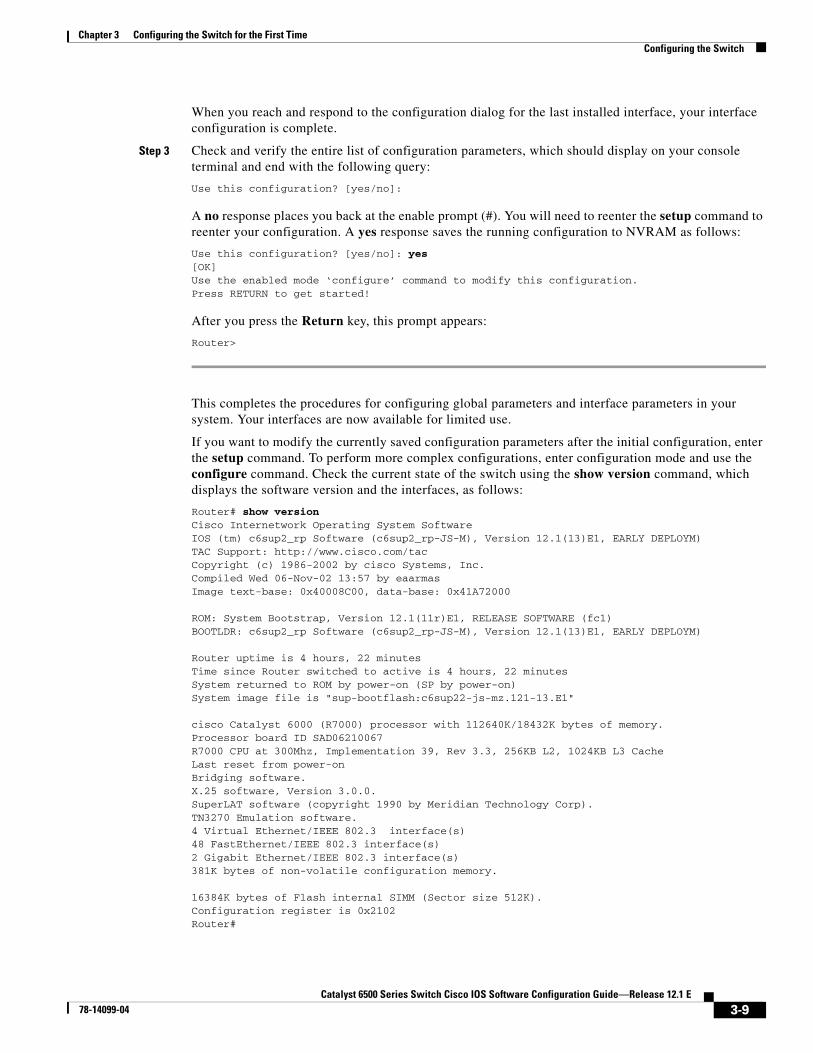
When you reach and respond to the configuration dialog for the last installed interface, your interface configuration is complete.
Step 3 Check and verify the entire list of configuration parameters, which should display on your console terminal and end with the following query:
Use this configuration? [yes/no]:
A no response places you back at the enable prompt (#). You will need to reenter the setup command to reenter your configuration. A yes response saves the running configuration to NVRAM as follows:
Use this configuration? [yes/no]: yes[OK]Use the enabled mode ‘configure’ command to modify this configuration.Press RETURN to get started!
After you press the Return key, this prompt appears:
Router>
This completes the procedures for configuring global parameters and interface parameters in your system. Your interfaces are now available for limited use.
If you want to modify the currently saved configuration parameters after the initial configuration, enter the setup command. To perform more complex configurations, enter configuration mode and use the configure command. Check the current state of the switch using the show version command, which displays the software version and the interfaces, as follows:
Router# show versionCisco Internetwork Operating System Software IOS (tm) c6sup2_rp Software (c6sup2_rp-JS-M), Version 12.1(13)E1, EARLY DEPLOYM)TAC Support: http://www.cisco.com/tacCopyright (c) 1986-2002 by cisco Systems, Inc.Compiled Wed 06-Nov-02 13:57 by eaarmasImage text-base: 0x40008C00, data-base: 0x41A72000
ROM: System Bootstrap, Version 12.1(11r)E1, RELEASE SOFTWARE (fc1)BOOTLDR: c6sup2_rp Software (c6sup2_rp-JS-M), Version 12.1(13)E1, EARLY DEPLOYM)
Router uptime is 4 hours, 22 minutesTime since Router switched to active is 4 hours, 22 minutesSystem returned to ROM by power-on (SP by power-on)System image file is "sup-bootflash:c6sup22-js-mz.121-13.E1"
cisco Catalyst 6000 (R7000) processor with 112640K/18432K bytes of memory.Processor board ID SAD06210067R7000 CPU at 300Mhz, Implementation 39, Rev 3.3, 256KB L2, 1024KB L3 CacheLast reset from power-onBridging software.X.25 software, Version 3.0.0.SuperLAT software (copyright 1990 by Meridian Technology Corp).TN3270 Emulation software.4 Virtual Ethernet/IEEE 802.3 interface(s)48 FastEthernet/IEEE 802.3 interface(s)2 Gigabit Ethernet/IEEE 802.3 interface(s)381K bytes of non-volatile configuration memory.
16384K bytes of Flash internal SIMM (Sector size 512K).Configuration register is 0x2102Router#
3-9Catalyst 6500 Series Switch Cisco IOS Software Configuration Guide—Release 12.1 E
78-14099-04

Chapter 3 Configuring the Switch for the First TimeConfiguring the Switch
For detailed interface configuration information, refer to the Cisco IOS Interface Configuration Guide at this URL:
http://www.cisco.com/univercd/cc/td/doc/product/software/ios121/121cgcr/inter_c/index.htm
Using Configuration ModeIf you prefer not to use the setup facility, you can configure the switch from configuration mode as follows:
Step 1 Connect a console terminal to the console interface of your supervisor engine.
Step 2 When you are asked if you want to enter the initial dialog, answer no to enter the normal operating mode as follows:
Would you like to enter the initial dialog? [yes]: no
Step 3 After a few seconds you will see the user EXEC prompt (Router>). Type enable to enter enable mode:
Router> enable
Note Configuration changes can only be made in enable mode.
The prompt will change to the privileged EXEC prompt (#) as follows:
Router#
Step 4 At the prompt (#), enter the configure terminal command to enter configuration mode as follows:
Router# configure terminalEnter configuration commands, one per line. End with CNTL/Z.Router(config)#
At the prompt, enter the interface type slot/interface command to enter interface configuration mode as follows:
Router(config)# interface fastethernet 5/1Router(config-if)#
In either of these configuration modes, you can enter any changes to the configuration. Enter the end command to exit configuration mode.
Step 5 Save your settings. (See the “Saving the Running Configuration Settings” section on page 3-11.)
Your switch is now minimally configured and can boot with the configuration you entered. To see a list of the configuration commands, enter ? at the prompt or press the help key in configuration mode.
Checking the Running Configuration Before Saving You can check the configuration settings you entered or changes you made by entering the show running-config command at the privileged EXEC prompt (#) as follows:
Router# show running-configBuilding configuration...
3-10Catalyst 6500 Series Switch Cisco IOS Software Configuration Guide—Release 12.1 E
78-14099-04

Chapter 3 Configuring the Switch for the First TimeConfiguring the Switch
Current configuration:Current configuration : 3441 bytes!version 12.1service timestamps debug datetime localtimeservice timestamps log datetime localtimeno service password-encryption!hostname Router!boot buffersize 522200boot system flash slot0:c6sup22-jsv-mz.121-5c.EX.binboot bootldr bootflash:c6msfc2-boot-mz.121-3a.E4enable password lab!redundancy main-cpu auto-sync standardip subnet-zerono ip finger!cns event-service server!<...output truncated...>!interface FastEthernet3/3 ip address 172.20.52.19 255.255.255.224!<...output truncated...>!line con 0 exec-timeout 0 0 transport input noneline vty 0 4 exec-timeout 0 0 password lab login transport input lat pad mop telnet rlogin udptn nasi!endRouter#
Saving the Running Configuration SettingsTo store the configuration or changes to your startup configuration in NVRAM, enter the copy running-config startup-config command at the privileged EXEC prompt (#) as follows:
Router# copy running-config startup-config
This command saves the configuration settings that you created in configuration mode. If you fail to do this step, your configuration will be lost the next time you reload the system.
Reviewing the ConfigurationTo display information stored in NVRAM, enter the show startup-config EXEC command. The display should be similar to the display from the show running-config EXEC command.
3-11Catalyst 6500 Series Switch Cisco IOS Software Configuration Guide—Release 12.1 E
78-14099-04
Chapter 3 Configuring the Switch for the First TimeConfiguring the Switch
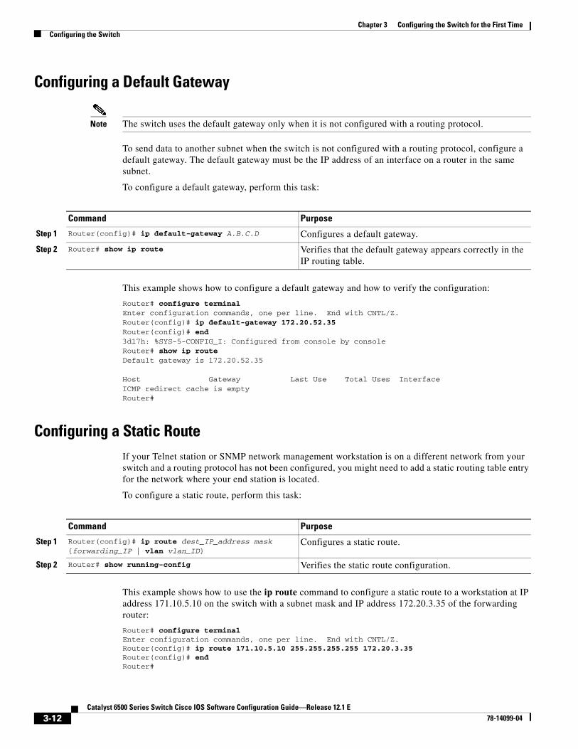
Configuring a Default Gateway
Note The switch uses the default gateway only when it is not configured with a routing protocol.
To send data to another subnet when the switch is not configured with a routing protocol, configure a default gateway. The default gateway must be the IP address of an interface on a router in the same subnet.
To configure a default gateway, perform this task:
This example shows how to configure a default gateway and how to verify the configuration:
Router# configure terminalEnter configuration commands, one per line. End with CNTL/Z.Router(config)# ip default-gateway 172.20.52.35Router(config)# end3d17h: %SYS-5-CONFIG_I: Configured from console by consoleRouter# show ip routeDefault gateway is 172.20.52.35
Host Gateway Last Use Total Uses InterfaceICMP redirect cache is emptyRouter#
Configuring a Static RouteIf your Telnet station or SNMP network management workstation is on a different network from your switch and a routing protocol has not been configured, you might need to add a static routing table entry for the network where your end station is located.
To configure a static route, perform this task:
This example shows how to use the ip route command to configure a static route to a workstation at IP address 171.10.5.10 on the switch with a subnet mask and IP address 172.20.3.35 of the forwarding router:
Router# configure terminalEnter configuration commands, one per line. End with CNTL/Z.Router(config)# ip route 171.10.5.10 255.255.255.255 172.20.3.35Router(config)# endRouter#
Command Purpose
Step 1 Router(config)# ip default-gateway A.B.C.D Configures a default gateway.
Step 2 Router# show ip route Verifies that the default gateway appears correctly in the IP routing table.
Command Purpose
Step 1 Router(config)# ip route dest_IP_address mask {forwarding_IP | vlan vlan_ID}
Configures a static route.
Step 2 Router# show running-config Verifies the static route configuration.
3-12Catalyst 6500 Series Switch Cisco IOS Software Configuration Guide—Release 12.1 E
78-14099-04

Chapter 3 Configuring the Switch for the First TimeConfiguring the Switch
This example shows how to use the show running-config command to confirm the configuration of the previously configured static route:
Router# show running-configBuilding configuration....<...output truncated...>.ip default-gateway 172.20.52.35ip classlessip route 171.10.5.10 255.255.255.255 172.20.3.35no ip http server!line con 0 transport input noneline vty 0 4 exec-timeout 0 0 password lab login transport input lat pad dsipcon mop telnet rlogin udptn nasi!end Router#
This example shows how to use the ip route command to configure a static route to a workstation at IP address 171.20.5.3 on the switch with subnet mask and connected over VLAN 1:
Router# configure terminalRouter(config)# ip route 171.20.5.3 255.255.255.255 vlan 1Router(config)# endRouter#
This example shows how to use the show running-config command to confirm the configuration of the previously configured static route:
Router# show running-configBuilding configuration....<...output truncated...>.ip default-gateway 172.20.52.35ip classlessip route 171.20.52.3 255.255.255.255 Vlan1no ip http server!!x25 host z!line con 0 transport input noneline vty 0 4 exec-timeout 0 0 password lab login transport input lat pad dsipcon mop telnet rlogin udptn nasi!end
Router#
3-13Catalyst 6500 Series Switch Cisco IOS Software Configuration Guide—Release 12.1 E
78-14099-04

Chapter 3 Configuring the Switch for the First TimeConfiguring the Switch
Configuring a BOOTP ServerThe Bootstrap Protocol (BOOTP) automatically assigns an IP address by adding the MAC and IP addresses of the interface to the BOOTP server configuration file. When the switch boots, it automatically retrieves the IP address from the BOOTP server.
The switch performs a BOOTP request only if the current IP address is set to 0.0.0.0. (This address is the default address for a new switch or a switch that has had its startup-config file cleared using the erase command.)
To allow your switch to retrieve its IP address from a BOOTP server, you must first determine the MAC address of the switch and add that MAC address to the BOOTP configuration file on the BOOTP server. To create a BOOTP server configuration file, follow these steps:
Step 1 Install the BOOTP server code on the workstation, if it is not already installed.
Step 2 Determine the MAC address from the label on the chassis.
Step 3 Add an entry in the BOOTP configuration file (usually /usr/etc/bootptab) for each switch. Press Return after each entry to create a blank line between each entry. See the example BOOTP configuration file that follows in Step 4.
Step 4 Enter the reload command to reboot and automatically request the IP address from the BOOTP server.
This example BOOTP configuration file shows the added entry:
# /etc/bootptab: database for bootp server (/etc/bootpd)## Blank lines and lines beginning with '#' are ignored.## Legend:## first field -- hostname# (may be full domain name and probably should be)## hd -- home directory# bf -- bootfile# cs -- cookie servers# ds -- domain name servers# gw -- gateways# ha -- hardware address# ht -- hardware type# im -- impress servers# ip -- host IP address# lg -- log servers# lp -- LPR servers# ns -- IEN-116 name servers# rl -- resource location protocol servers# sm -- subnet mask# tc -- template host (points to similar host entry)# to -- time offset (seconds)# ts -- time servers#<information deleted>########################################################################### Start of individual host entries#########################################################################Router: tc=netcisco0: ha=0000.0ca7.ce00: ip=172.31.7.97:dross: tc=netcisco0: ha=00000c000139: ip=172.31.7.26:<information deleted>
3-14Catalyst 6500 Series Switch Cisco IOS Software Configuration Guide—Release 12.1 E
78-14099-04

Chapter 3 Configuring the Switch for the First TimeProtecting Access to Privileged EXEC Commands
Protecting Access to Privileged EXEC CommandsThe following tasks provide a way to control access to the system configuration file and privileged EXEC commands:
• Setting or Changing a Static Enable Password, page 3-15
• Using the enable password and enable secret Commands, page 3-15
• Setting or Changing a Line Password, page 3-16
• Setting TACACS+ Password Protection for Privileged EXEC Mode, page 3-16
• Encrypting Passwords, page 3-17
• Configuring Multiple Privilege Levels, page 3-17
Setting or Changing a Static Enable Password To set or change a static password that controls access to the privileged EXEC mode, perform this task:
This example shows how to configure an enable password as “lab” at the privileged EXEC mode:
Router# configure terminalRouter(config)# enable password labRouter(config)#
To display the password or access level configuration, see the “Displaying the Password, Access Level, and Privilege Level Configuration” section on page 3-19.
Using the enable password and enable secret CommandsTo provide an additional layer of security, particularly for passwords that cross the network or that are stored on a TFTP server, you can use either the enable password or enable secret commands. Both commands configure an encrypted password that you must enter to access enable mode (the default) or to access a specified privilege level. We recommend that you use the enable secret command.
If you configure the enable secret command, it takes precedence over the enable password command; the two commands cannot be in effect simultaneously.
To configure the switch to require an enable password, perform either of these tasks:
Command Purpose
Router(config)# enable password password Sets a new password or changes an existing password for the privileged EXEC mode.
Command Purpose
Router(config)# enable password [level level] {password | encryption-type encrypted-password}
Establishes a password for the privileged EXEC mode.
Router(config)# enable secret [level level] {password | encryption-type encrypted-password}
Specifies a secret password, saved using a nonreversible encryption method. (If enable password and enable secret commands are both set, users must enter the enable secret password.)
3-15Catalyst 6500 Series Switch Cisco IOS Software Configuration Guide—Release 12.1 E
78-14099-04

Chapter 3 Configuring the Switch for the First TimeProtecting Access to Privileged EXEC Commands
Use either of these commands with the level option to define a password for a specific privilege level. After you specify the level and set a password, give the password only to users who need to have access at this level. Use the privilege level configuration command to specify commands accessible at various levels.
If you enable the service password-encryption command, the password you enter is encrypted. When you display it with the more system:running-config command, it displays in encrypted form.
If you specify an encryption type, you must provide an encrypted password that you copy from another Catalyst 6500 series switch configuration.
Note You cannot recover a lost encrypted password. You must clear NVRAM and set a new password. See the “Recovering a Lost Enable Password” section on page 3-19 if you lose or forget your password.
To display the password or access level configuration, see the “Displaying the Password, Access Level, and Privilege Level Configuration” section on page 3-19.
Setting or Changing a Line Password To set or change a password on a line, perform this task:
To display the password or access level configuration, see the “Displaying the Password, Access Level, and Privilege Level Configuration” section on page 3-19.
Setting TACACS+ Password Protection for Privileged EXEC ModeFor complete information about TACACS+, refer to these publications:
• Cisco IOS Security Configuration Guide, Release 12.1, “Authentication, Authorization, and Accounting (AAA),” at this URL:
http://www.cisco.com/univercd/cc/td/doc/product/software/ios121/121cgcr/secur_c/scprt1/index.htm
• Cisco IOS Security Command Reference, Release 12.1, at this URL:
http://www.cisco.com/univercd/cc/td/doc/product/software/ios121/121cgcr/secur_r/index.htm
To set the TACACS+ protocol to determine whether or not a user can access privileged EXEC mode, perform this task:
Command Purpose
Router(config-line)# password password Sets a new password or change an existing password for the privileged level.
Command Purpose
Router(config)# enable use-tacacs Sets the TACACS-style user ID and password-checking mechanism for the privileged EXEC mode.
3-16Catalyst 6500 Series Switch Cisco IOS Software Configuration Guide—Release 12.1 E
78-14099-04

Chapter 3 Configuring the Switch for the First TimeProtecting Access to Privileged EXEC Commands
When you set TACACS password protection at the privileged EXEC mode, the enable EXEC command prompts for both a new username and a password. This information is then sent to the TACACS+ server for authentication. If you are using the extended TACACS+, it also sends any existing UNIX user identification code to the TACACS+ server.
Caution If you enter the enable use-tacacs command, you must also enter tacacs-server authenticate enable, or you are locked out of the privileged EXEC mode.
Note When used without extended TACACS, the enable use-tacacs command allows anyone with a valid username and password to access the privileged EXEC mode, creating a potential security problem. This problem occurs because the switch cannot tell the difference between a query resulting from entering the enable command and an attempt to log in without extended TACACS.
Encrypting PasswordsBecause protocol analyzers can examine packets (and read passwords), you can increase access security by configuring the Cisco IOS software to encrypt passwords. Encryption prevents the password from being readable in the configuration file.
To configure the Cisco IOS software to encrypt passwords, perform this task:
Encryption occurs when the current configuration is written or when a password is configured. Password encryption is applied to all passwords, including authentication key passwords, the privileged command password, console and virtual terminal line access passwords, and Border Gateway Protocol (BGP) neighbor passwords. The service password-encryption command keeps unauthorized individuals from viewing your password in your configuration file.
Caution The service password-encryption command does not provide a high level of network security. If you use this command, you should also take additional network security measures.
Although you cannot recover a lost encrypted password (that is, you cannot get the original password back), you can regain control of the switch after you lose or forget the encrypted password. See the “Recovering a Lost Enable Password” section on page 3-19 if you lose or forget your password.
To display the password or access level configuration, see the “Displaying the Password, Access Level, and Privilege Level Configuration” section on page 3-19.
Configuring Multiple Privilege LevelsBy default, the Cisco IOS software has two modes of password security: user EXEC mode and privileged EXEC mode. You can configure up to 16 hierarchical levels of commands for each mode. By configuring multiple passwords, you can allow different sets of users to have access to specified commands.
Command Purpose
Router(config)# service password-encryption Encrypts a password.
3-17Catalyst 6500 Series Switch Cisco IOS Software Configuration Guide—Release 12.1 E
78-14099-04

Chapter 3 Configuring the Switch for the First TimeProtecting Access to Privileged EXEC Commands
For example, if you want many users to have access to the clear line command, you can assign it level 2 security and distribute the level 2 password widely. If you want more restricted access to the configure command, you can assign it level 3 security and distribute that password to more restricted users.
These tasks describe how to configure additional levels of security:
• Setting the Privilege Level for a Command, page 3-18
• Changing the Default Privilege Level for Lines, page 3-18
• Logging In to a Privilege Level, page 3-18
• Exiting a Privilege Level, page 3-19
• Displaying the Password, Access Level, and Privilege Level Configuration, page 3-19
Setting the Privilege Level for a Command
To set the privilege level for a command, perform this task:
To display the password or access level configuration, see the “Displaying the Password, Access Level, and Privilege Level Configuration” section on page 3-19.
Changing the Default Privilege Level for Lines
To change the default privilege level for a given line or a group of lines, perform this task:
To display the password or access level configuration, see the “Displaying the Password, Access Level, and Privilege Level Configuration” section on page 3-19.
Logging In to a Privilege Level
To log in at a specified privilege level, perform this task:
Command Purpose
Step 1 Router(config)# privilege mode level level command
Sets the privilege level for a command.
Step 2 Router(config)# enable password level level [encryption-type] password
Specifies the enable password for a privilege level.
Command Purpose
Router(config-line)# privilege level level Changes the default privilege level for the line.
Command Purpose
Router# enable level Logs into a specified privilege level.
3-18Catalyst 6500 Series Switch Cisco IOS Software Configuration Guide—Release 12.1 E
78-14099-04

Chapter 3 Configuring the Switch for the First TimeRecovering a Lost Enable Password
Exiting a Privilege Level
To exit to a specified privilege level, perform this task:
Displaying the Password, Access Level, and Privilege Level Configuration
To display the password, access level, and privilege level configuration, perform this task:
This example shows how to display the password and access level configuration:
Router# show running-config<...output truncated...>enable password lab<...output truncated...>
This example shows how to display the privilege level configuration:
Router# show privilegeCurrent privilege level is 15Router#
Recovering a Lost Enable PasswordTo recover a lost enable password, follow these steps:
Step 1 Connect to the console interface.
Step 2 Configure the switch to boot up without reading the configuration memory (NVRAM).
Step 3 Reboot the system.
Step 4 Access enable mode (which can be done without a password when one is not configured).
Step 5 View or change the password, or erase the configuration.
Step 6 Reconfigure the switch to boot up and read the NVRAM as it normally does.
Step 7 Reboot the system.
Note Password recovery requires the Break signal. You must be familiar with how your terminal or PC terminal emulator issues this signal. For example, in ProComm, the Alt-B keys generate the Break signal. In a Windows terminal session, you press the Break or Ctrl and Break keys simultaneously.
Command PurposeRouter# disable level Exits to a specified privilege level.
Command Purpose
Step 1 Router# show running-config Displays the password and the access level configuration.
Step 2 Router# show privilege Shows the privilege level configuration.
3-19Catalyst 6500 Series Switch Cisco IOS Software Configuration Guide—Release 12.1 E
78-14099-04

Chapter 3 Configuring the Switch for the First TimeModifying the Supervisor Engine Startup Configuration
Modifying the Supervisor Engine Startup ConfigurationThese sections describe how the startup configuration on the supervisor engine works and how to modify the configuration register and BOOT variable:
• Understanding the Supervisor Engine Boot Configuration, page 3-20
• Configuring the Software Configuration Register, page 3-21
• Specifying the Startup System Image, page 3-24
• Understanding Flash Memory, page 3-24
• BOOTLDR Environment Variable, page 3-25
• CONFIG_FILE Environment Variable, page 3-26
• Controlling Environment Variables, page 3-26
Understanding the Supervisor Engine Boot ConfigurationThese next sections describe how the boot configuration works on the supervisor engine.
Understanding the Supervisor Engine Boot Process
The supervisor engine boot process involves two software images: ROM monitor and supervisor engine software. When the switch is powered up or reset, the ROM-monitor code is executed. Depending on the NVRAM configuration, the supervisor engine either stays in ROM-monitor mode or loads the supervisor engine software.
Two user-configurable parameters determine how the switch boots: the configuration register and the BOOT environment variable. The configuration register is described in the “Modifying the Boot Field and Using the boot Command” section on page 3-22. The BOOT environment variable is described in the “Specifying the Startup System Image” section on page 3-24.
Understanding the ROM Monitor
The ROM monitor executes upon power-up, reset, or when a fatal exception occurs. The switch enters ROM-monitor mode if the switch does not find a valid software image, if the NVRAM configuration is corrupted, or if the configuration register is set to enter ROM-monitor mode. From ROM-monitor mode, you can manually load a software image from bootflash or a Flash PC card.
Note For complete syntax and usage information for the ROM monitor commands, refer to the Catalyst 6500 Series Switch Cisco IOS Command Reference publication.
You can also enter ROM-monitor mode by restarting and then pressing the Break key during the first 60 seconds of startup. If you are connected through a terminal server, you can escape to the Telnet prompt and enter the send break command to enter ROM-monitor mode.
Note The Break key is always enabled for 60 seconds after rebooting, regardless of whether the configuration-register setting has the Break key disabled.
3-20Catalyst 6500 Series Switch Cisco IOS Software Configuration Guide—Release 12.1 E
78-14099-04

Chapter 3 Configuring the Switch for the First TimeModifying the Supervisor Engine Startup Configuration
The ROM monitor has these features:
• Power-on confidence test
• Hardware initialization
• Boot capability (manual boot and autoboot)
• Debug utility and crash analysis
• Monitor call interface (EMT calls—the ROM monitor provides information and some functionality to the running software images through EMT calls)
• File system (the ROM monitor knows the simple file system and supports the newly developed file system through the dynamic linked file system library [MONLIB])
• Exception handling
Configuring the Software Configuration RegisterThe switch uses a 16-bit software configuration register, which allows you to set specific system parameters. Settings for the software configuration register are written into NVRAM.
Following are some reasons for changing the software configuration register settings:
• To select a boot source and default boot filename.
• To enable or disable the Break function.
• To control broadcast addresses.
• To set the console terminal baud rate.
• To load operating software from Flash memory.
• To recover a lost password.
• To allow you to manually boot the system using the boot command at the bootstrap program prompt.
• To force an automatic boot from the system bootstrap software (boot image) or from a default system image in onboard Flash memory, and read any boot system commands that are stored in the configuration file in NVRAM.
Table 3-2 lists the meaning of each of the software configuration memory bits, and Table 3-3 defines the boot field.
Caution The recommended configuration register setting is 0x2102. If you configure a setting that leaves break enabled and you send a break sequence over a console connection, the switch drops into ROMMON.
Table 3-2 Software Configuration Register Bit Meaning
Bit Number1 Hexadecimal Meaning
00 to 03 0x0000 to 0x000F Boot field (see Table 3-3)
06 0x0040 Causes system software to ignore NVRAM contents
07 0x0080 OEM2 bit enabled
08 0x0100 Break disabled
09 0x0200 Use secondary bootstrap
10 0x0400 Internet Protocol (IP) broadcast with all zeros
3-21Catalyst 6500 Series Switch Cisco IOS Software Configuration Guide—Release 12.1 E
78-14099-04

Chapter 3 Configuring the Switch for the First TimeModifying the Supervisor Engine Startup Configuration
Modifying the Boot Field and Using the boot Command
The configuration register boot field determines whether or not the switch loads an operating system image, and if so, where it obtains this system image. The following sections describe using and setting the configuration register boot field, and the tasks you must perform to modify the configuration register boot field.
Bits 0 through 3 of the software configuration register form the boot field.
Note The factory default configuration register setting for systems and spares is 0x2102.
When the boot field is set to either 0 or 1 (0-0-0-0 or 0-0-0-1), the system ignores any boot instructions in the system configuration file and the following occurs:
• When the boot field is set to 0, you must boot the operating system manually by entering the boot command to the system bootstrap program or ROM monitor.
• When the boot field is set to 1, the system boots the first image in the onboard bootflash single in-line memory module (SIMM).
• When the entire boot field equals a value between 0-0-1-0 and 1-1-1-1, the switch loads the system image specified by boot system commands in the startup configuration file.
You can enter the boot command only, or enter the command and include additional boot instructions, such as the name of a file stored in Flash memory, or a file that you specify for booting from a network server. If you use the boot command without specifying a file or any other boot instructions, the system boots from the default Flash image (the first image in onboard Flash memory). Otherwise, you can instruct the system to boot from a specific Flash image (using the boot system flash filename command).
You can also use the boot command to boot images stored in the Flash PC cards located in Flash PC card slot 0 or slot 1 on the supervisor engine. If you set the boot field to any bit pattern other than 0 or 1, the system uses the resulting number to form a filename for booting over the network.
You must set the boot field for the boot functions you require.
11 to 12 0x0800 to 0x1000 Console line speed (default is 9600 baud)
13 0x2000 Boot default Flash software if network boot fails
14 0x4000 IP broadcasts do not have network numbers
15 0x8000 Enable diagnostic messages and ignore NVRAM contents
1. The factory default value for the configuration register is 0x2102.
2. OEM = original equipment manufacturer.
Table 3-3 Explanation of Boot Field (Configuration Register Bits 00 to 03)
Boot Field Meaning
00 Stays at the system bootstrap prompt
01 Boots the first system image in onboard Flash memory
02 to 0F Specifies a default filename for booting over the network; enables boot system commands that override the default filename
Table 3-2 Software Configuration Register Bit Meaning (continued)
Bit Number1 Hexadecimal Meaning
3-22Catalyst 6500 Series Switch Cisco IOS Software Configuration Guide—Release 12.1 E
78-14099-04
Chapter 3 Configuring the Switch for the First TimeModifying the Supervisor Engine Startup Configuration
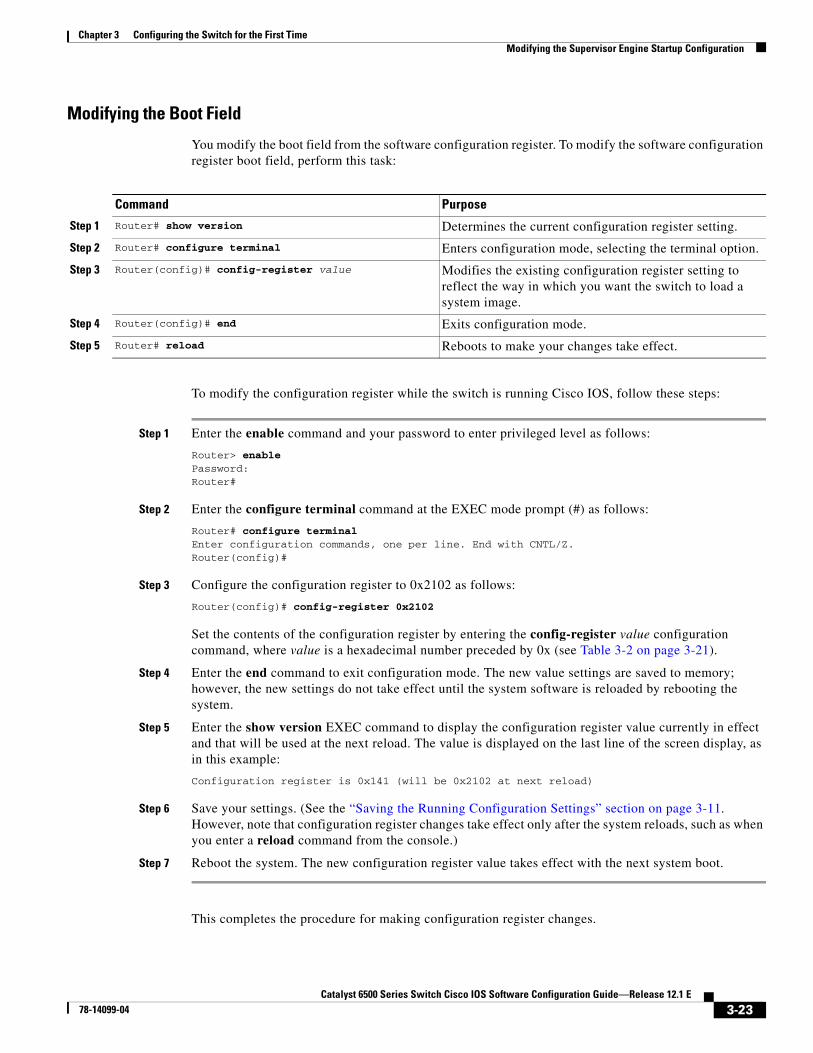
Modifying the Boot Field
You modify the boot field from the software configuration register. To modify the software configuration register boot field, perform this task:
To modify the configuration register while the switch is running Cisco IOS, follow these steps:
Step 1 Enter the enable command and your password to enter privileged level as follows:
Router> enablePassword: Router#
Step 2 Enter the configure terminal command at the EXEC mode prompt (#) as follows:
Router# configure terminalEnter configuration commands, one per line. End with CNTL/Z.Router(config)#
Step 3 Configure the configuration register to 0x2102 as follows:
Router(config)# config-register 0x2102
Set the contents of the configuration register by entering the config-register value configuration command, where value is a hexadecimal number preceded by 0x (see Table 3-2 on page 3-21).
Step 4 Enter the end command to exit configuration mode. The new value settings are saved to memory; however, the new settings do not take effect until the system software is reloaded by rebooting the system.
Step 5 Enter the show version EXEC command to display the configuration register value currently in effect and that will be used at the next reload. The value is displayed on the last line of the screen display, as in this example:
Configuration register is 0x141 (will be 0x2102 at next reload)
Step 6 Save your settings. (See the “Saving the Running Configuration Settings” section on page 3-11. However, note that configuration register changes take effect only after the system reloads, such as when you enter a reload command from the console.)
Step 7 Reboot the system. The new configuration register value takes effect with the next system boot.
This completes the procedure for making configuration register changes.
Command Purpose
Step 1 Router# show version Determines the current configuration register setting.
Step 2 Router# configure terminal Enters configuration mode, selecting the terminal option.
Step 3 Router(config)# config-register value Modifies the existing configuration register setting to reflect the way in which you want the switch to load a system image.
Step 4 Router(config)# end Exits configuration mode.
Step 5 Router# reload Reboots to make your changes take effect.
3-23Catalyst 6500 Series Switch Cisco IOS Software Configuration Guide—Release 12.1 E
78-14099-04

Chapter 3 Configuring the Switch for the First TimeModifying the Supervisor Engine Startup Configuration
Verifying the Configuration Register Setting
Enter the show version EXEC command to verify the current configuration register setting. In ROM-monitor mode, enter the o command to verify the value of the configuration register boot field.
To verify the configuration register setting, perform this task:
In this example, the show version command indicates that the current configuration register is set so that the switch does not automatically load an operating system image. Instead, it enters ROM-monitor mode and waits for user-entered ROM monitor commands. The new setting instructs the switch to load a system image from commands in the startup configuration file or from a default system image stored on a network server.
Router1# show version | include Configuration register Configuration register is 0x2102Router#
Specifying the Startup System ImageYou can enter multiple boot commands in the startup configuration file or in the BOOT environment variable to provide backup methods for loading a system image.
Note Store the system software image in the sup-bootflash: or slot0: device, not in the bootflash: device. Store the boot loader image, if any, in the MSFC bootflash: device.
The BOOT environment variable is also described in the “Specify the Startup System Image in the Configuration File” section in the “Loading and Maintaining System Images and Microcode” chapter of the Cisco IOS Configuration Fundamentals Configuration Guide.
Understanding Flash MemoryThe following sections describe Flash memory:
• Flash Memory Features, page 3-25
• Security Features, page 3-25
• Flash Memory Configuration Process, page 3-25
Note The descriptions in the following sections applies to both the bootflash device and to removable Flash memory cards.
Command Purpose
Router# show version | include Configuration register Displays the configuration register setting.
3-24Catalyst 6500 Series Switch Cisco IOS Software Configuration Guide—Release 12.1 E
78-14099-04

Chapter 3 Configuring the Switch for the First TimeModifying the Supervisor Engine Startup Configuration
Flash Memory Features
The Flash memory components allow you to do the following:
• Copy the system image to Flash memory using TFTP.
• Copy the system image to Flash memory using rcp.
• Boot the system from Flash memory either automatically or manually.
• Copy the Flash memory image to a network server using TFTP or rcp.
• Boot manually or automatically from a system software image stored in Flash memory.
Security Features
The Flash memory components support the following security features:
• Flash memory cards contain a write-protect switch that you can use to protect data. You must set the switch to unprotected to write data to the Flash PC card.
• The system image stored in Flash memory can be changed only from privileged EXEC level on the console terminal.
Flash Memory Configuration Process
To configure your switch to boot from Flash memory, follow these steps:
Step 1 Copy a system image to Flash memory using TFTP or rcp (refer to the Cisco IOS Configuration Fundamentals Configuration Guide, Release 12.1, “Cisco IOS File Management,” “Loading and Maintaining System Images,” at this URL:
http://www.cisco.com/univercd/cc/td/doc/product/software/ios121/121cgcr/fun_c/fcprt2/fcd203.htm
Step 2 Configure the system to boot automatically from the file in Flash memory. You might need to change the configuration register value. See the “Modifying the Boot Field and Using the boot Command” section on page 3-22, for more information on modifying the configuration register.
Step 3 Save your configurations.
Step 4 Power cycle and reboot your system to ensure that all is working as expected.
BOOTLDR Environment VariableThe BOOTLDR environment specifies the Flash file system and filename containing the boot loader image.
Caution With a Supervisor Engine 1 and MSFC1, do not erase the boot loader image from the MSFC1 bootflash: device. The boot loader must be present in the MSFC1 bootflash: device to boot a Supervisor Engine 1 and MSFC1 successfully.
3-25Catalyst 6500 Series Switch Cisco IOS Software Configuration Guide—Release 12.1 E
78-14099-04

Chapter 3 Configuring the Switch for the First TimeModifying the Supervisor Engine Startup Configuration
CONFIG_FILE Environment VariableFor Class A Flash file systems, the CONFIG_FILE environment variable specifies the file system and filename of the configuration file to use for initialization (startup). Valid file systems can include nvram:, slot0:, and sup-bootflash:.
For detailed file management configuration information, refer to the Cisco IOS Configuration Fundamentals Configuration Guide at this URL:
http://www.cisco.com/univercd/cc/td/doc/product/software/ios121/121cgcr/fun_c/index.htm
After you save the CONFIG_FILE environment variable to your startup configuration, the switch checks the variable upon startup to determine the location and filename of the configuration file to use for initialization.
The switch uses the NVRAM configuration during initialization when the CONFIG_FILE environment variable does not exist or when it is null (such as at first-time startup). If the switch detects a problem with NVRAM or a checksum error, the switch enters setup mode. See the “Using the Setup Facility or the setup Command” section on page 3-2 for more information on the setup command facility.
Controlling Environment VariablesAlthough the ROM monitor controls environment variables, you can create, modify, or view them with certain commands. To create or modify the BOOT, BOOTLDR, and CONFIG_FILE environment variables, use the boot system, boot bootldr, and boot config global configuration commands.
Refer to the “Specify the Startup System Image in the Configuration File” section in the “Loading and Maintaining System Images and Microcode” chapter of the Configuration Fundamentals Configuration Guide for details on setting the BOOT environment variable. Refer to the “Specify the Startup Configuration File” section in the “Modifying, Downloading, and Maintaining Configuration Files” chapter of the Configuration Fundamentals Configuration Guide for details on setting the CONFIG_FILE variable.
Note When you use the boot system, boot bootldr, and boot config global configuration commands, you affect only the running configuration. You must save the environment variable settings to your startup configuration to place the information under ROM monitor control and for the environment variables to function as expected. Enter the copy system:running-config nvram:startup-config command to save the environment variables from your running configuration to your startup configuration.
You can view the contents of the BOOT, BOOTLDR, and the CONFIG_FILE environment variables using the show bootvar command. This command displays the settings for these variables as they exist in the startup configuration as well as in the running configuration if a running configuration setting differs from a startup configuration setting.
This example shows how to check the BOOT, BOOTLDR, and the CONFIG_FILE environment variables:
Router# show bootvarBOOT variable = slot0:c6sup22-jsv-mz.121-5c.EX.bin,1;CONFIG_FILE variable does not existBOOTLDR variable = bootflash:c6msfc2-boot-mz.121-3a.E4Configuration register is 0x2Router#
To display the contents of the configuration file pointed to by the CONFIG_FILE environment variable, enter the more nvram:startup-config command.
3-26Catalyst 6500 Series Switch Cisco IOS Software Configuration Guide—Release 12.1 E
78-14099-04

Chapter 3 Configuring the Switch for the First TimeModifying the Supervisor Engine Startup Configuration
Setting the BOOTLDR Environment Variable
To set the BOOTLDR environment variable, perform this task:
This example shows how to set the BOOTLDR variable:
Router# dir bootflash:Directory of bootflash:/
1 -rw- 1599488 Nov 29 1999 11:12:29 c6msfc-boot-mz.120-7.XE.bin
15990784 bytes total (14391168 bytes free)Router# configure terminalRouter (config)# boot bootldr bootflash:c6msfc-boot-mz.120-7.XE.bin Router (config)# endRouter# copy system:running-config nvram:startup-config[ok]Router# show bootvarBOOT variable = sup-bootflash:c6sup-js-mz.120-7.XE.bin,1;CONFIG_FILE variable does not existBOOTLDR variable = bootflash:c6msfc-boot-mz.120-7.XE.binConfiguration register is 0x0
Command Purpose
Step 1 Router# dir bootflash: Verifies that bootflash contains the boot loader image.
Step 2 Router# configure terminal Enters the configuration mode from the terminal.
Step 3 Router(config)# boot bootldr bootflash:boot_loader
Sets the BOOTLDR environment variable to specify the Flash device and filename of the boot loader image. This step modifies the runtime BOOTLDR environment variable.
Step 4 Router# end Exits configuration mode.
Step 5 Router# copy system:running-confignvram:startup-config
Saves this runtime BOOTLDR environment variable to your startup configuration.
Step 6 Router# show bootvar (Optional) Verifies the contents of the BOOTLDR environment variable.
3-27Catalyst 6500 Series Switch Cisco IOS Software Configuration Guide—Release 12.1 E
78-14099-04

Chapter 3 Configuring the Switch for the First TimeModifying the Supervisor Engine Startup Configuration
3-28Catalyst 6500 Series Switch Cisco IOS Software Configuration Guide—Release 12.1 E
78-14099-04