dnv-oss-103: rules for classification of floating …. 3 supplementary requirements for service...
TRANSCRIPT
OFFSHORE SERVICE SPECIFICATION
The content of thaccepts that it is verification servipursuant to this dconsequences aris
The electronic
DNV-OSS-103
Rules for Classification of Floating LNG/LPG Production, Storage
and Loading UnitsAPRIL 2012
DET NORSKE VERITAS AS
is service document is the subject of intellectual property rights reserved by Det Norske Veritas AS (DNV). The userprohibited by anyone else but DNV and/or its licensees to offer and/or perform classification, certification and/orces, including the issuance of certificates and/or declarations of conformity, wholly or partly, on the basis of and/orocument whether free of charge or chargeable, without DNV's prior written consent. DNV is not responsible for theing from any use of this document by others.
pdf version of this document found through http://www.dnv.com is the officially binding version

FOREWORD
DET NORSKE VERITAS (DNV) is an autonomous and independent foundation with the objectives of safeguarding life,property and the environment, at sea and onshore. DNV undertakes classification, certification, and other verification andconsultancy services relating to quality of ships, offshore units and installations, and onshore industries worldwide, andcarries out research in relation to these functions.
DNV service documents consist of among others the following types of documents:— Service Specifications. Procedural requirements.— Standards. Technical requirements.— Recommended Practices. Guidance.
The Standards and Recommended Practices are offered within the following areas:A) Qualification, Quality and Safety MethodologyB) Materials TechnologyC) StructuresD) SystemsE) Special FacilitiesF) Pipelines and RisersG) Asset OperationH) Marine OperationsJ) Cleaner EnergyO) Subsea Systems
© Det Norske Veritas AS April 2012
Any comments may be sent by e-mail to [email protected]
If any person suffers loss or damage which is proved to have been caused by any negligent act or omission of Det Norske Veritas, then Det Norske Veritas shall pay compensation tosuch person for his proved direct loss or damage. However, the compensation shall not exceed an amount equal to ten times the fee charged for the service in question, provided thatthe maximum compensation shall never exceed USD 2 million.In this provision "Det Norske Veritas" shall mean the Foundation Det Norske Veritas as well as all its subsidiaries, directors, officers, employees, agents and any other acting on behalfof Det Norske Veritas.

Offshore Service Specification DNV-OSS-103, April 2012Changes – Page 3
CHANGES
GeneralThis document supersedes DNV-OSS-301, June 2011.
Text affected by the main changes in this edition is highlighted in red colour. However, if the changes involvea whole chapter, section or sub-section, normally only the title will be in red colour.The present edition of the rules includes amendments and additions decided by the Executive Committee inMarch 2012.
Main Changes coming into force 1 October 2012General— Innovative/ alternative designs shall be approved under a separate agreed scheme possible based on TQ
systematics. — Included references for the new notations/ updated:
— HELDK qualifiers i.e. SHF and N— ISDS— OFFLOADING
— Included documentation as expected for asbestos in line with MODU code/SOLAS update. — Excluded DRILL notation from document (not relevant).— Handling of POSMOOR/DP notations in operation.— Inclusion of the QSP approach as introduced in OSS-101 (Apri12011).
Minor amendments:— Corrected some capitals letters.— More uniform approach to acronyms (ref. CC and MO).— Corrected some typos.— Updated/ simplified documentation requirements description.
• Ch.1— Sec.1 B new 202, 213, 236, 246, 258 and 268. New reference in Table C1.— Sec.2 A200 new text in 204 and 205. A500 text deleted and A1001 changes in text.— Sec.3 New A202. Table B3 changed.— Sec.4 A204, A205, A401, A502, A601, A602, A702, A703 and A705 changes in text.— Sec.5 New A105, B700.— Sec.7 A100 new limited liability.
• Ch.2— Sec.1 Documentation requirements deleted.— Sec.2 Documentation requirements deleted. New sub-section L. “Preparation for Surveys and Inspections
on Location”. Changes in Table M1.— Sec.3 Documentation requirements deleted. Sub-section I. in previous edition of document “Preparation for
Surveys and Inspections on Location” in previous edition of document deleted.— Sec.4 Documentation requirements deleted.— Sec.6 Changes in Table A1. A400 Documentation requirements deleted. Sub-section I. “Drilling Plant”
deleted. New text in sub-section I. “Helicopter Decks”. Changes in Table R1 and T1.
• Ch.3— Sec.1 Changes in Table B1.— Sec.4 Text changes in B101, E101 and G205. New E104.— Sec.6 New B102 and C105. Changes in G101.— Sec.7 New text and changes in G500 and H100.— App.B Changes in B502.
DET NORSKE VERITAS AS

Offshore Service Specification DNV-OSS-103, April 2012 Contents – Page 4
CONTENTS
CH. 1 PRINCIPLES AND PROCEDURES FOR CLASSIFICATION................................................. 15
Sec. 1 Introduction ...................................................................................................................................... 16
A. General .......................................................................................................................................................................... 16A 100 General................................................................................................................................................................ 16A 200 Organisation of DNV-OSS-103.......................................................................................................................... 16A 300 Objects covered................................................................................................................................................... 16
B. Definitions..................................................................................................................................................................... 16B 100 Verbal forms ....................................................................................................................................................... 16B 200 Definitions .......................................................................................................................................................... 16
C. Normative References................................................................................................................................................... 20C 100 General................................................................................................................................................................ 20C 200 DNV reference documents.................................................................................................................................. 20C 300 Other references .................................................................................................................................................. 21
D. Informative References ................................................................................................................................................. 21D 100 DNV Offshore Service Specifications ................................................................................................................ 21D 200 Other references .................................................................................................................................................. 21
E. Abbreviations ................................................................................................................................................................ 22E 100 General................................................................................................................................................................ 22
Sec. 2 Classification Principles................................................................................................................... 23
A. The Classification Concept ........................................................................................................................................... 23A 100 Introduction......................................................................................................................................................... 23A 200 Applicable Rules................................................................................................................................................. 23A 300 Basis for assignment of class .............................................................................................................................. 24A 400 Basis for maintenance of class............................................................................................................................ 24A 500 Documentation.................................................................................................................................................... 24A 600 Disclosure of information ................................................................................................................................... 25A 700 Access ................................................................................................................................................................ 26A 800 Calibration of equipment .................................................................................................................................... 26A 900 Service suppliers ................................................................................................................................................. 26A 1000 Limitation of DNV's responsibility..................................................................................................................... 26
B. Appeals.......................................................................................................................................................................... 26B 100 Decisions taken by the Society .......................................................................................................................... 26
C. Statutory Certification................................................................................................................................................... 27C 100 General ............................................................................................................................................................... 27C 200 Service suppliers ................................................................................................................................................. 27
Sec. 3 Classification Scope and Notations................................................................................................. 28
A. Scope of Classification.................................................................................................................................................. 28A 100 General................................................................................................................................................................ 28A 200 Rule parts ............................................................................................................................................................ 28A 300 Rule particulars ................................................................................................................................................... 28
B. Class Notations ............................................................................................................................................................. 28B 100 General................................................................................................................................................................ 28B 200 Construction symbols ......................................................................................................................................... 29B 300 Main character of class ....................................................................................................................................... 29B 400 Basic design notations ........................................................................................................................................ 29B 500 Service notations................................................................................................................................................. 29B 600 Additional class; special equipment and systems notations ............................................................................... 30B 700 Optional class notations related to cold climate operation ................................................................................. 32B 800 Special feature notations ..................................................................................................................................... 32B 900 Limitations of class ............................................................................................................................................. 33B 1000 Compliance with coastal state legislation ........................................................................................................... 33B 1100 Combination of notations.................................................................................................................................... 33
Sec. 4 Assignment of Class ......................................................................................................................... 34
A. Assignment of Class - New Vessels ............................................................................................................................. 34A 100 General................................................................................................................................................................ 34A 200 Requirements for builder or designer ................................................................................................................. 34
DET NORSKE VERITAS AS

Offshore Service Specification DNV-OSS-103, April 2012 Contents – Page 5
A 300 Applicable Rules ................................................................................................................................................ 34A 400 Plan approval ...................................................................................................................................................... 35A 500 Survey during construction ................................................................................................................................. 35A 600 Installation of systems and equipment................................................................................................................ 36A 700 Testing and Commissioning ............................................................................................................................... 36
B. Assignment of Class - Existing Vessels........................................................................................................................ 36B 100 General................................................................................................................................................................ 36B 200 Applicable Rules ................................................................................................................................................ 36B 300 Design Approval ................................................................................................................................................ 36B 400 Class entry survey ............................................................................................................................................... 36
C. The Class Certificate ..................................................................................................................................................... 37C 100 General................................................................................................................................................................ 37C 200 Late commissioning ............................................................................................................................................ 37
D. The Register of Vessels................................................................................................................................................. 37D 100 General................................................................................................................................................................ 37
Sec. 5 Retention of Class............................................................................................................................. 38
A. Conditions for Retention of Class ................................................................................................................................. 38A 100 General requirements .......................................................................................................................................... 38A 200 The customer’s obligations ................................................................................................................................. 38A 300 Maintenance........................................................................................................................................................ 38
B. Classification Society Involvement .............................................................................................................................. 39B 100 Applicable Rules................................................................................................................................................. 39B 200 Surveys................................................................................................................................................................ 39B 300 Conditions and Memoranda................................................................................................................................ 39B 400 Survey reports and survey status......................................................................................................................... 40B 500 Damage and repairs............................................................................................................................................. 40B 600 Conversions and alterations ................................................................................................................................ 40B 700 Temporary equipment......................................................................................................................................... 41
C. Endorsement and Renewal of the Class Certificate ...................................................................................................... 41C 100 Endorsement of the class certificate ................................................................................................................... 41C 200 Renewal of the class certificate........................................................................................................................... 42
D. Suspension and Withdrawal of Class............................................................................................................................ 42D 100 General................................................................................................................................................................ 42D 200 Suspension of class ............................................................................................................................................. 42D 300 Reinstatement following class suspension.......................................................................................................... 43D 400 Withdrawal of class............................................................................................................................................. 43D 500 Re-assignment of class following class withdrawal ........................................................................................... 43
E. Change of Owner or Manager....................................................................................................................................... 43E 100 General................................................................................................................................................................ 43
F. Force Majeure ............................................................................................................................................................... 43F 100 General................................................................................................................................................................ 43
Sec. 6 Certification of Materials, Components and Systems................................................................... 45
A. General .......................................................................................................................................................................... 45A 100 General................................................................................................................................................................ 45A 200 Requirements for manufacturer .......................................................................................................................... 45
B. The Classification Involvement .................................................................................................................................... 45B 100 General................................................................................................................................................................ 45B 200 Plan approval ...................................................................................................................................................... 45B 300 Type approval ..................................................................................................................................................... 46B 400 Survey ................................................................................................................................................................. 46B 500 Manufacturing survey arrangement .................................................................................................................... 46
C. Suspension and Withdrawal of Certificates .................................................................................................................. 47C 100 General................................................................................................................................................................ 47
Sec. 7 Legal Provisions................................................................................................................................ 48
A. Liability and Jurisdiction .............................................................................................................................................. 48A 100 Limited liability .................................................................................................................................................. 48A 200 Use by other parties ............................................................................................................................................ 48A 300 Governing law..................................................................................................................................................... 48A 400 Venue .................................................................................................................................................................. 48
DET NORSKE VERITAS AS

Offshore Service Specification DNV-OSS-103, April 2012 Contents – Page 6
CH. 2 DESIGN AND CONSTRUCTION PROVISIONS ....................................................................... 49
Sec. 1 Design and Construction Requirements for 1A1 MOU Main Class ........................................... 50
A. General .......................................................................................................................................................................... 50A 100 Introduction......................................................................................................................................................... 50A 200 Technical reference documents........................................................................................................................... 50A 300 General assumptions ........................................................................................................................................... 50
B. Safety Principles and Arrangement............................................................................................................................... 50B 100 General................................................................................................................................................................ 50B 200 Design principles ................................................................................................................................................ 51B 300 Arrangement ....................................................................................................................................................... 51B 400 Escape and evacuation ........................................................................................................................................ 51
C. Materials........................................................................................................................................................................ 51C 100 Technical requirements....................................................................................................................................... 51C 200 Supplementary classification requirements ........................................................................................................ 51
D. Structural Design........................................................................................................................................................... 51D 100 Technical requirements....................................................................................................................................... 51
E. Fabrication and Testing of Offshore Structures ............................................................................................................ 51E 100 Technical requirements....................................................................................................................................... 51E 200 Supplementary classification requirements ........................................................................................................ 52
F. Stability and Watertight/Weathertight Integrity ........................................................................................................... 52F 100 Technical requirements....................................................................................................................................... 52
G. Position Keeping and Towing....................................................................................................................................... 52G 100 General................................................................................................................................................................ 52G 200 Ship-shaped units ................................................................................................................................................ 52G 300 Column-stabilised units ...................................................................................................................................... 52G 400 Self-elevating, tension leg and deep draught units ............................................................................................. 52G 500 Towing ................................................................................................................................................................ 52G 600 Supplementary classification requirements ........................................................................................................ 53
H. Marine and Machinery Systems and Equipment .......................................................................................................... 53H 100 Technical requirements....................................................................................................................................... 53H 200 Supplementary classification requirements ........................................................................................................ 53
I. Electrical Systems and Equipment................................................................................................................................ 53I 100 Technical requirements....................................................................................................................................... 53I 200 Supplementary classification requirements ........................................................................................................ 53
J. Instrumentation and Telecommunication Systems ....................................................................................................... 53J 100 Technical requirements....................................................................................................................................... 53J 200 Supplementary classification requirements ........................................................................................................ 54
K. Fire Protection............................................................................................................................................................... 54K 100 Technical requirements....................................................................................................................................... 54K 200 Supplementary classification requirements ........................................................................................................ 54
L. Summary of Technical Reference Standards ................................................................................................................ 54L 100 General................................................................................................................................................................ 54
Sec. 2 Design and Construction Requirements for OI Floating Offshore Installation Main Class......................................................................................................................................... 56
A. General .......................................................................................................................................................................... 56A 100 Introduction......................................................................................................................................................... 56A 200 Technical reference documents........................................................................................................................... 56A 300 General assumptions ........................................................................................................................................... 56A 400 Certification of materials and components ......................................................................................................... 57
B. Safety Principles and Arrangement............................................................................................................................... 57B 100 General................................................................................................................................................................ 57B 200 Design principles ................................................................................................................................................ 57B 300 Arrangement ....................................................................................................................................................... 57B 400 Escape and evacuation ........................................................................................................................................ 57
C. Materials........................................................................................................................................................................ 57C 100 Technical requirements....................................................................................................................................... 57C 200 Supplementary classification requirements ........................................................................................................ 57
DET NORSKE VERITAS AS

Offshore Service Specification DNV-OSS-103, April 2012 Contents – Page 7
D. Structural Design........................................................................................................................................................... 57D 100 Technical requirements....................................................................................................................................... 57
E. Fabrication and Testing of Offshore Structures ............................................................................................................ 58E 100 Technical requirements....................................................................................................................................... 58E 200 Supplementary classification requirements ........................................................................................................ 58
F. Stability and Watertight Integrity ................................................................................................................................. 58F 100 Technical requirements....................................................................................................................................... 58
G. Position Keeping and Towing....................................................................................................................................... 58G 100 General................................................................................................................................................................ 58G 200 Supplementary classification requirements ........................................................................................................ 58
H. Utility Systems and Equipment..................................................................................................................................... 58H 100 Technical requirements....................................................................................................................................... 58H 200 Supplementary classification requirements ........................................................................................................ 59
I. Electrical Systems and Equipment................................................................................................................................ 59I 100 Technical requirements....................................................................................................................................... 59I 200 Supplementary classification requirements ........................................................................................................ 59
J. Instrumentation and Telecommunication Systems ....................................................................................................... 59J 100 Technical requirements....................................................................................................................................... 59J 200 Supplementary classification requirements ........................................................................................................ 59
K. Fire Protection............................................................................................................................................................... 60K 100 Technical requirements....................................................................................................................................... 60K 200 Supplementary classification requirements ........................................................................................................ 60
L. Preparation for Surveys and Inspections on Location .................................................................................................. 60L 100 General................................................................................................................................................................ 60
M. Summary of Technical Reference Standards ................................................................................................................ 61M 100 General................................................................................................................................................................ 61
Sec. 3 Supplementary Requirements for Service Notation LNG (or LPG) Production Unit or Installation ....................................................................................................................................... 62
A. General .......................................................................................................................................................................... 62A 100 Introduction......................................................................................................................................................... 62
B. Safety Principles and Arrangement............................................................................................................................... 62B 100 General................................................................................................................................................................ 62B 200 Arrangement ....................................................................................................................................................... 62B 300 Area classification............................................................................................................................................... 62B 400 Emergency shutdown.......................................................................................................................................... 62B 500 Escape, evacuation and communication ............................................................................................................. 62
C. Structural Design........................................................................................................................................................... 62C 100 General................................................................................................................................................................ 62C 200 Supplementary technical requirements ............................................................................................................... 62
D. Marine and Machinery and Utility Systems ................................................................................................................. 63D 100 General................................................................................................................................................................ 63D 200 Supplementary technical requirements ............................................................................................................... 63
E. Instrumentation and Telecommunication Systems ....................................................................................................... 63E 100 Supplementary technical requirements ............................................................................................................... 63
F. Fire Protection............................................................................................................................................................... 63F 100 General................................................................................................................................................................ 63F 200 Supplementary technical requirements ............................................................................................................... 63
G. Position Keeping ........................................................................................................................................................... 63G 100 General................................................................................................................................................................ 63
H. Industrial Equipment..................................................................................................................................................... 63H 100 General................................................................................................................................................................ 63
I. Hydrocarbon Import and Export ................................................................................................................................... 64I 100 General................................................................................................................................................................ 64I 200 Hydrocarbon import............................................................................................................................................ 64I 300 Hydrocarbon Offloading .................................................................................................................................... 64
DET NORSKE VERITAS AS

Offshore Service Specification DNV-OSS-103, April 2012 Contents – Page 8
Sec. 4 Supplementary Requirements for Service Notation LNG (or LPG) Storage Unit or Installation ....................................................................................................................................... 65
A. General .......................................................................................................................................................................... 65A 100 Introduction......................................................................................................................................................... 65
B. Safety Principles and Arrangement............................................................................................................................... 65B 100 General................................................................................................................................................................ 65B 200 Arrangement ....................................................................................................................................................... 65B 300 Area classification............................................................................................................................................... 65B 400 Emergency shutdown.......................................................................................................................................... 65B 500 Escape, evacuation and communication ............................................................................................................. 65
C. Structural Design........................................................................................................................................................... 65C 100 General................................................................................................................................................................ 65C 200 Supplementary technical requirements ............................................................................................................... 65
D. Marine and Machinery or Utility Systems and Equipment........................................................................................... 66D 100 General................................................................................................................................................................ 66D 200 Supplementary technical requirements ............................................................................................................... 66
E. Instrumentation and Telecommunication Systems ....................................................................................................... 66E 100 Supplementary technical requirements ............................................................................................................... 66
F. Fire Protection............................................................................................................................................................... 66F 100 General................................................................................................................................................................ 66F 200 Supplementary technical requirements ............................................................................................................... 66
G. Position Keeping ........................................................................................................................................................... 67G 100 General................................................................................................................................................................ 67
H. Export/Import of LNG/LPG/Condensate...................................................................................................................... 67H 100 General................................................................................................................................................................ 67
I. Preparation for Surveys and Inspections on Location .................................................................................................. 67I 100 General................................................................................................................................................................ 67
Sec. 5 Supplementary Requirements for Service Notation LNG (or LPG) Loading Unit or Installation ....................................................................................................................................... 68
A. General .......................................................................................................................................................................... 68A 100 Introduction......................................................................................................................................................... 68A 200 Design requirements ........................................................................................................................................... 68
Sec. 6 Additional Class Notations: Design and Construction Requirements for Special Equipment and Systems....................................................................................................................................... 69
A. Introduction................................................................................................................................................................... 69A 100 General................................................................................................................................................................ 69A 200 Technical reference documents........................................................................................................................... 70A 300 General assumptions ........................................................................................................................................... 70
B. Position Mooring System.............................................................................................................................................. 70B 100 General................................................................................................................................................................ 70B 200 Technical requirements....................................................................................................................................... 71B 300 Certification of materials and components ......................................................................................................... 71
C. Dynamic Positioning Systems ...................................................................................................................................... 71C 100 General................................................................................................................................................................ 71C 200 Technical requirements....................................................................................................................................... 71
D. Single Point Mooring (SPM) ........................................................................................................................................ 71D 100 General................................................................................................................................................................ 71D 200 Technical requirements....................................................................................................................................... 71
E. Loading computer ........................................................................................................................................................ 72E 100 General................................................................................................................................................................ 72E 200 Technical requirements....................................................................................................................................... 72
F. Bow Loading................................................................................................................................................................. 72F 100 General................................................................................................................................................................ 72F 200 Technical requirements....................................................................................................................................... 72
G. Submerged Turret Loading ........................................................................................................................................... 72G 100 General................................................................................................................................................................ 72G 200 Technical requirements....................................................................................................................................... 72
DET NORSKE VERITAS AS
Offshore Service Specification DNV-OSS-103, April 2012 Contents – Page 9
H. Hydrocarbon Production Plant...................................................................................................................................... 72H 100 General................................................................................................................................................................ 72H 200 Technical requirements....................................................................................................................................... 72H 300 Certification of materials and components ......................................................................................................... 72
I. Helicopter Decks........................................................................................................................................................... 73I 100 General................................................................................................................................................................ 73I 200 Technical requirements....................................................................................................................................... 73
J. Crane Installations ........................................................................................................................................................ 73J 100 General................................................................................................................................................................ 73J 200 Technical requirements....................................................................................................................................... 73J 300 Certification of materials and components ......................................................................................................... 73
K. Additional Fire Protection ............................................................................................................................................ 73K 100 General................................................................................................................................................................ 73K 200 Technical requirements....................................................................................................................................... 74
L. Winterization, Cold Climate and Ice Notations ............................................................................................................ 74L 100 General................................................................................................................................................................ 74L 200 Operation of column-stabilised units in ice conditions ...................................................................................... 74
M. Hull Monitoring System................................................................................................................................................ 74M 100 General................................................................................................................................................................ 74M 200 Technical requirements....................................................................................................................................... 74
N. Fatigue Methodology for Ship-Shaped Units ............................................................................................................... 75N 100 General................................................................................................................................................................ 75N 200 Technical requirements....................................................................................................................................... 75
O. Environmental Notations .............................................................................................................................................. 75O 100 Additional oil pollution prevention measures fuel oil systems........................................................................... 75O 200 CLEAN or CLEAN DESIGN.............................................................................................................. 75O 300 Vapour Control Systems (VCS) ......................................................................................................................... 76O 400 RECYCLABLE ................................................................................................................................................. 76
P. Management of Safety and Environmental Protection ................................................................................................. 76P 100 General................................................................................................................................................................ 76P 200 Technical requirements....................................................................................................................................... 76
Q. Noise, Vibration and Comfort Rating Notations .......................................................................................................... 76Q 100 General................................................................................................................................................................ 76Q 200 Vibration class .................................................................................................................................................... 76Q 300 Comfort class ...................................................................................................................................................... 77
R. Integrated Software-dependent Systems. ...................................................................................................................... 77R 100 General................................................................................................................................................................ 77
S. Special Feature Notations ............................................................................................................................................. 77S 100 General................................................................................................................................................................ 77S 200 Special feature notation SUB ............................................................................................................................. 77S 300 Special feature notation HOT (…°C) ................................................................................................................. 77S 400 Special feature notation COAT-1 and COAT-2 ................................................................................................ 77S 500 Tailshaft monitoring - TMON ............................................................................................................................ 77S 600 Special Feature Notation BIS ............................................................................................................................ 78
T. Summary of Reference Documents for Additional Class Notations ............................................................................ 78T 100 General................................................................................................................................................................ 78
CH. 3 CLASSIFICATION IN OPERATION........................................................................................... 80
Sec. 1 General Provisions for Periodical Surveys .................................................................................... 81
A. General .......................................................................................................................................................................... 81A 100 Introduction......................................................................................................................................................... 81A 200 Survey pre-planning and record keeping ........................................................................................................... 81A 300 Accessibility and facilities for surveys on location ............................................................................................ 81
B. Periodical Surveys......................................................................................................................................................... 81B 100 General................................................................................................................................................................ 81B 200 Postponement of periodical surveys ................................................................................................................... 82B 300 Survey of units out of commission ..................................................................................................................... 82B 400 Survey Schedules ................................................................................................................................................ 83
DET NORSKE VERITAS AS
Offshore Service Specification DNV-OSS-103, April 2012 Contents – Page 10
Sec. 2 General Requirements for Hull and Machinery Surveys............................................................. 87
A. General .......................................................................................................................................................................... 87A 100 Preparation for survey......................................................................................................................................... 87
B. Requirements for Hull Surveys..................................................................................................................................... 87B 100 Conditions for survey and access to structures ................................................................................................... 87B 200 Survey extent ..................................................................................................................................................... 88B 300 Repair of structural damage or deterioration ...................................................................................................... 88
C. Requirements for Machinery Surveys........................................................................................................................... 89C 100 Maintenance and preparation for survey............................................................................................................. 89C 200 Replacement of Machinery Components............................................................................................................ 89C 300 Machinery verification........................................................................................................................................ 89
D. Special Provisions for Ageing Units ............................................................................................................................. 90D 100 General................................................................................................................................................................ 90D 200 Column-stabilised units ...................................................................................................................................... 91D 300 Self-elevating units ............................................................................................................................................. 91D 400 Ship-shaped units ................................................................................................................................................ 91
Sec. 3 Alternative Survey Arrangements and Surveys Performed by Approved Companies ............. 92
A. Alternative Survey Arrangements................................................................................................................................. 92A 100 General overview of survey arrangements ......................................................................................................... 92A 200 Hull PMS (Planned Maintenance System) ......................................................................................................... 92A 300 Survey arrangement based on Reliability Centred Maintenance (RCM) system ............................................... 92
B. Surveys by Approved Companies or Service Suppliers ............................................................................................... 93B 100 General................................................................................................................................................................ 93B 200 Thickness measurements .................................................................................................................................... 93B 300 Bottom survey afloat........................................................................................................................................... 94B 400 Non-destructive testing ...................................................................................................................................... 94B 500 Mooring chain inspections.................................................................................................................................. 94B 600 Condition monitoring.......................................................................................................................................... 94
Sec. 4 Periodical Survey Extent for Main Class ....................................................................................... 95
A. General .......................................................................................................................................................................... 95A 100 Introduction......................................................................................................................................................... 95A 200 Hull survey - general........................................................................................................................................... 95A 300 Extent of hull survey........................................................................................................................................... 95
B. Annual Survey............................................................................................................................................................... 98B 100 Survey extent ...................................................................................................................................................... 98B 200 Hull and equipment for ship-shaped units .......................................................................................................... 98B 300 Structure and equipment for column-stabilised and self-elevating units............................................................ 98B 400 Machinery and safety systems for ship-shaped units or installations ................................................................. 99B 500 Machinery and safety systems for column-stabilised and self-elevating units or installations .......................... 99
C. Intermediate Survey .................................................................................................................................................... 100C 100 General.............................................................................................................................................................. 100C 200 Hull and equipment for ship-shaped units ........................................................................................................ 100C 300 Structure and equipment for column-stabilised and self-elevating units or installations ................................. 100C 400 Machinery and safety systems for ship-shaped units or installations ............................................................... 100C 500 Machinery and safety systems for column-stabilised and self-elevating units or installations ........................ 100
D. Renewal Survey, Structure and Equipment ................................................................................................................ 100D 100 Hull and equipment of ship-shaped units ......................................................................................................... 100D 200 Column-stabilised and self-elevating structures .............................................................................................. 101D 300 Alternative survey............................................................................................................................................. 103
E. Renewal Survey, Machinery and Safety Systems....................................................................................................... 103E 100 General.............................................................................................................................................................. 103E 200 Electrical installations....................................................................................................................................... 104E 300 Instrumentation and automation ....................................................................................................................... 104
F. Renewal Survey, Tailshaft Survey.............................................................................................................................. 105F 100 Standard requirements ...................................................................................................................................... 105F 200 Alternative survey............................................................................................................................................. 105F 300 Tailshaft condition monitoring survey arrangement......................................................................................... 105
G. Survey of Geared Thrusters for Main Propulsion and positioning ............................................................................. 105G 100 Definitions ........................................................................................................................................................ 105G 200 Survey extent .................................................................................................................................................... 105
DET NORSKE VERITAS AS

Offshore Service Specification DNV-OSS-103, April 2012 Contents – Page 11
H. Survey of Podded Thrusters for Main Propulsion and positioning............................................................................. 106H 100 General.............................................................................................................................................................. 106H 200 Scheduled surveys............................................................................................................................................. 107
I. Boiler Survey .............................................................................................................................................................. 107I 100 General.............................................................................................................................................................. 107
J. Thermal Oil Heater Survey ......................................................................................................................................... 107J 100 General.............................................................................................................................................................. 107
K. Survey of the outside of Unit's Bottom and Related Items ......................................................................................... 107K 100 Schedule ........................................................................................................................................................... 107K 200 Parts to be examined ........................................................................................................................................ 108K 300 Survey planning and record keeping ................................................................................................................ 108
L. Survey of Towing, Temporary and Position Mooring Equipment ............................................................................. 108L 100 Types of survey................................................................................................................................................. 108L 200 Annual survey ................................................................................................................................................... 108L 300 Intermediate survey........................................................................................................................................... 108L 400 Renewal survey................................................................................................................................................. 108L 500 Anchor chains; acceptance criteria and repair .................................................................................................. 108
Sec. 5 Periodical Survey Extent for Additional Service Notations ....................................................... 111
A. General ........................................................................................................................................................................ 111A 100 Introduction....................................................................................................................................................... 111
B. LNG or LPG Production and/or LNG or LPG Storage Units and Installations ......................................................... 111B 100 Application........................................................................................................................................................ 111B 200 Survey arrangement .......................................................................................................................................... 111B 300 Annual survey ................................................................................................................................................... 111B 400 Cargo Handling and Containment System – Annual Survey ........................................................................... 112B 500 Complete periodical survey .............................................................................................................................. 112B 600 Cargo Handling and Containment System – Complete Periodical Survey ...................................................... 112
C. LNG/LPG Loading Units and Installations ................................................................................................................ 113C 100 Application........................................................................................................................................................ 113C 200 Survey arrangement .......................................................................................................................................... 113
Sec. 6 Periodical Survey Extent for Additional Class; Special Equipment and System Notations ................................................................................... 114
A. General ........................................................................................................................................................................ 114A 100 Introduction....................................................................................................................................................... 114
B. Position Mooring Equipment ...................................................................................................................................... 114B 100 Application........................................................................................................................................................ 114B 200 Types of surveys ............................................................................................................................................... 114B 300 Annual survey ................................................................................................................................................... 115B 400 Intermediate survey........................................................................................................................................... 115B 500 Complete periodical survey of fairleads and winches irrespective of fatigue life factors of
the mooring system........................................................................................................................................... 115B 600 Complete periodical survey - systems designed before 1996 (no fatigue analysis and corrosion allowance) . 115B 700 Complete periodical survey – fatigue design life factor 3 ................................................................................ 116B 800 Complete periodical survey – fatigue life factor 5-8 or greater........................................................................ 117
C. Dynamic Positioning System ...................................................................................................................................... 117C 100 General.............................................................................................................................................................. 117C 200 Annual survey ................................................................................................................................................... 118C 300 Complete survey (5 years) ................................................................................................................................ 118
D. Single Point Mooring .................................................................................................................................................. 119D 100 Application........................................................................................................................................................ 119D 200 Annual survey ................................................................................................................................................... 119
E. Loading Computers for Damage Control.................................................................................................................... 120E 100 Application........................................................................................................................................................ 120E 200 Annual survey ................................................................................................................................................... 120
F. Production Plant .......................................................................................................................................................... 120F 100 Application........................................................................................................................................................ 120F 200 Survey arrangement .......................................................................................................................................... 120F 300 Annual survey ................................................................................................................................................... 120F 400 Complete periodical survey .............................................................................................................................. 121
DET NORSKE VERITAS AS

Offshore Service Specification DNV-OSS-103, April 2012 Contents – Page 12
G. Helicopter Deck .......................................................................................................................................................... 121G 100 Application........................................................................................................................................................ 121G 200 Complete periodical survey .............................................................................................................................. 121
H. Crane ........................................................................................................................................................................... 121H 100 Application........................................................................................................................................................ 121H 200 Annual survey ................................................................................................................................................... 122H 300 Complete periodical survey .............................................................................................................................. 122
I. Additional Fire Protection........................................................................................................................................... 122I 100 Application........................................................................................................................................................ 122I 200 Complete periodical survey, all F-class notations ............................................................................................ 122I 300 Complete periodical survey, F-A...................................................................................................................... 123I 400 Complete periodical survey, F-M ..................................................................................................................... 123I 500 Complete periodical survey, F-C...................................................................................................................... 123I 600 Complete periodical survey, F-AM .................................................................................................................. 123I 700 Complete periodical survey, F-AC................................................................................................................... 123I 800 Complete periodical survey, F-MC .................................................................................................................. 123I 900 Complete periodical survey, F-AMC ............................................................................................................... 123
J. Winterization, Cold climate and Ice ........................................................................................................................... 123J 100 Winterization .................................................................................................................................................... 123J 200 Deicing and anti-icing systems ......................................................................................................................... 124
K. Periodically Unattended Machinery Space and Machinery Centralised Operated ..................................................... 124K 100 Application........................................................................................................................................................ 124K 200 Annual survey ................................................................................................................................................... 124K 300 Complete periodical survey .............................................................................................................................. 124
L. Hull Monitoring System.............................................................................................................................................. 125L 100 Application........................................................................................................................................................ 125L 200 General.............................................................................................................................................................. 125L 300 Annual survey ................................................................................................................................................... 125
M. Fatigue Methodology for Ship-Shaped Units ............................................................................................................ 125M 100 Application........................................................................................................................................................ 125M 200 General.............................................................................................................................................................. 125M 300 Annual survey ................................................................................................................................................... 125M 400 Intermediate survey........................................................................................................................................... 125M 500 Complete periodical survey .............................................................................................................................. 125
N. Environmental notations ............................................................................................................................................. 126N 100 Additional oil pollution prevention measures - fuel oil systems ...................................................................... 126N 200 CLEAN or CLEAN DESIGN............................................................................................................ 126N 300 Vapour Control Systems (VCS) ....................................................................................................................... 126
O. Safety and Environmental Protection Management System....................................................................................... 127O 100 Application........................................................................................................................................................ 127O 200 Survey requirements ......................................................................................................................................... 127
P. Noise, Vibration and Comfort Rating ......................................................................................................................... 127P 100 General.............................................................................................................................................................. 127
Q. Special Feature Notations ........................................................................................................................................... 127Q 100 Tailshaft Monitoring ......................................................................................................................................... 127
Sec. 7 Machinery Alternative Survey Arrangements ............................................................................ 129
A. General ........................................................................................................................................................................ 129A 100 General.............................................................................................................................................................. 129A 200 Machinery survey arrangements ....................................................................................................................... 132
B. Machinery Renewal .................................................................................................................................................... 133B 100 General.............................................................................................................................................................. 133B 200 Annual survey ................................................................................................................................................... 133B 300 Renewal survey................................................................................................................................................. 133B 400 Structure and equipment for column-stabilised and self-elevating units.......................................................... 133B 500 Machinery and safety systems for ship-shaped units or installations ............................................................... 133B 600 Machinery and safety systems for column-stabilised and self-elevating units or installations ........................ 133
C. Machinery Continuous ................................................................................................................................................ 134C 100 General.............................................................................................................................................................. 134C 200 Annual survey ................................................................................................................................................... 135C 300 Renewal survey................................................................................................................................................. 135
DET NORSKE VERITAS AS

Offshore Service Specification DNV-OSS-103, April 2012 Contents – Page 13
D. Machinery PMS (Planned Maintenance System)................................................................................................................................... 135
D 100 General.............................................................................................................................................................. 135
E. Machinery CM (Condition Monitoring) ..................................................................................................................... 137E 100 General.............................................................................................................................................................. 137E 200 Approval of CM programme ............................................................................................................................ 137E 300 Implementation survey ..................................................................................................................................... 138E 400 Annual survey ................................................................................................................................................... 138E 500 Renewal survey................................................................................................................................................. 138
F. Gas Turbines ............................................................................................................................................................... 138F 100 General.............................................................................................................................................................. 138F 200 Annual survey ................................................................................................................................................... 139F 300 Renewal survey................................................................................................................................................. 139
G. PMS RCM................................................................................................................................................................... 139G 100 General.............................................................................................................................................................. 139G 200 Approval of RCM based maintenance programme .......................................................................................... 140G 300 Implementation survey ..................................................................................................................................... 140G 400 Annual Survey .................................................................................................................................................. 140G 500 Renewal survey................................................................................................................................................. 141
H. Offshore CM (Condition Monitoring) ........................................................................................................................ 141H 100 General.............................................................................................................................................................. 141H 200 Implementation survey ..................................................................................................................................... 142H 300 Annual survey ................................................................................................................................................... 142H 400 Approval of service provider ............................................................................................................................ 143H 500 Renewal audit of service provider .................................................................................................................... 143H 600 Random audit .................................................................................................................................................... 143
App. A Special Considerations for Conversions....................................................................................... 144
A. Basic Principles........................................................................................................................................................... 144A 100 Introduction....................................................................................................................................................... 144A 200 Assumptions...................................................................................................................................................... 144A 300 Main principles ................................................................................................................................................. 144
B. Class Notations ........................................................................................................................................................... 145B 100 Conversions ...................................................................................................................................................... 145
C. Technical Guidance for Classification ........................................................................................................................ 145C 100 General.............................................................................................................................................................. 145C 200 Hull and topside structures ............................................................................................................................... 145C 300 Hull condition ................................................................................................................................................... 145C 400 Hull strength in benign environment ................................................................................................................ 145C 500 Fatigue assessment............................................................................................................................................ 146C 600 Topside support structure.................................................................................................................................. 146C 700 Mooring ............................................................................................................................................................ 146C 800 Marine systems and equipment......................................................................................................................... 146C 900 Electrical and instrumentation .......................................................................................................................... 147C 1000 Safety systems and arrangement....................................................................................................................... 147
D. Additional Services ..................................................................................................................................................... 147D 100 General.............................................................................................................................................................. 147
App. B Introduction to Offshore Classification........................................................................................ 148
A. Introduction................................................................................................................................................................. 148A 100 Purpose.............................................................................................................................................................. 148
B. The Classification System........................................................................................................................................... 148B 100 The classification process and its limitations ................................................................................................... 148B 200 Who needs classification?................................................................................................................................. 148B 300 Recognition of DNV......................................................................................................................................... 148B 400 Responsibility for safety at sea ......................................................................................................................... 149B 500 Classification of newbuildings.......................................................................................................................... 149B 600 Classification in the operational phase ............................................................................................................. 149B 700 Owner's duties................................................................................................................................................... 149
C. Remuneration .............................................................................................................................................................. 150C 100 Fee system......................................................................................................................................................... 150
D. Classification Support ................................................................................................................................................. 150D 100 General.............................................................................................................................................................. 150
DET NORSKE VERITAS AS

Offshore Service Specification DNV-OSS-103, April 2012 Contents – Page 14
D 200 Pre-contract support .......................................................................................................................................... 150D 300 In-service support.............................................................................................................................................. 150D 400 Limitations ........................................................................................................................................................ 150
DET NORSKE VERITAS AS

OFFSHORE SERVICE SPECIFICATIONDNV-OSS-103
RULES FOR CLASSIFICATION OF FLOATING LNG/LPGPRODUCTION, STORAGE AND LOADING UNITS
CHAPTER 1
PRINCIPLES AND PROCEDURES FOR CLASSIFICATION
CONTENTS PAGE
Sec. 1 Introduction........................................................................................................................ 16Sec. 2 Classification Principles..................................................................................................... 23Sec. 3 Classification Scope and Notations ................................................................................... 28Sec. 4 Assignment of Class .......................................................................................................... 34Sec. 5 Retention of Class .............................................................................................................. 38Sec. 6 Certification of Materials, Components and Systems........................................................ 45Sec. 7 Legal Provisions................................................................................................................. 48
DET NORSKE VERITAS AS

Offshore Service Specification DNV-OSS-103, April 2012Ch.1 Sec.1 – Page 16
SECTION 1INTRODUCTION
A. General
A 100 General101 This publication, DNV-OSS-103, presents DNV’s Rules for Classification of Floating LNG/LPGProduction and Storage Units or Installations, stating the terms and procedures for assigning and maintainingclassification, including listing of the applicable technical references to be applied for classification.
A 200 Organisation of DNV-OSS-103201 DNV-OSS-103 is divided into three main chapters as follows:
— Chapter 1: providing general information about classification principles and procedures— Chapter 2: providing design and construction requirements for the newbuilding phase— Chapter 3: providing requirements for maintenance of class in the operational phase.
A 300 Objects covered301 DNV-OSS-103 covers classification of floating offshore objects for the following services:
— LNG/LPG production— LNG/LPG storage and offloading— LNG/LPG loading (buoy).
Although this document refers primarily to liquefied natural gas (LNG) and liquefied petroleum gas (LPG), theprinciples herein may also be used for other offshore gas installations such as those involving primarilycompressed natural gas (CNG), and gas to liquid (GTL) products. A floating offshore installation which processes hydrocarbons and refrigerates gas to produce LNG will betermed here an LNG FPSO (LNG floating production, storage and offloading unit). LNG FPSOs are alsocommonly termed FLNG. The installation may be fed gas directly from a gas well or a gas network or mayprocess associated gas in conjunction with oil production. Such units may also produce, store and offloadquantities of LPG and condensate.A floating offshore installation which processes hydrocarbons and refrigerates gas to produce LPG will betermed here an LPG FPSO (LPG floating production, storage and offloading unit). The installation may be fedgas directly from a gas well or a gas network or may process associated gas in conjunction with oil production.Such units may also produce, store and offload quantities of condensate.An offshore installation which receives and regasifies LNG is termed an FSRU (floating storage andregasification unit). The storage and hull may generally follow the requirements to a storage unit described inCh.2 Sec.4. The regasification plant and safety systems may follow the requirements in DNV ClassificationNote 61.3 Regasification Vessels. FSRUs which follow a ship class regime may refer to DNV Rules for ShipsPt.5 Ch.5 and DNV Classification Note 61.3.Note: This document addresses floating steel structures. Concrete structures, both floating and bottom fixedhave also been proposed for offshore gas applications. For such designs reference is also made to DNVOffshore Standard DNV-OS-C503 Concrete LNG Terminal Structures and Containment Systems. Where suchunits are classified, the principles in this document may be applied.
B. Definitions
B 100 Verbal forms101 Shall: Indicates a mandatory requirement to be followed for fulfilment or compliance with the presentservice specification. Deviations are not permitted unless formally and rigorously justified, and accepted by allrelevant contracting parties. 102 Should: Indicates that among several possibilities one is recommended as particularly suitable, withoutmentioning or excluding others, or that a certain course of action is preferred but not necessarily required. Otherpossibilities may be applied subject to agreement.103 May: Verbal form used to indicate a course of action permissible within the limits of the servicespecification.
B 200 Definitions201 Approval or approved: Denotes acceptance by DNV of documentation showing design solutions,arrangements and/or equipment to comply with the Rules.
DET NORSKE VERITAS AS

Offshore Service Specification DNV-OSS-103, April 2012Ch.1 Sec.1 – Page 17
202 Assessment: An Act of assessing, appraising or evaluating a condition of a product, process or system.
203 Assigning class: Originally signified designation of one of several classes to a unit based on its condition,ranging from good to bad. Today only the highest class is assigned, comprising the main class 1A1 for mobileoffshore units and OI for permanently placed installations, together with an obligatory additional class notation,e.g. LNG Production Unit, where applicable.
Voluntary additional class notations may also be assigned covering special service, equipment or systems, e.g.PROD (LNG) denoting a classed LNG production plant.
204 The Board: Signifies the Executive Board of the Society.
205 Builder: Signifies the party contracted to build or convert a unit in compliance with the Society’s Rules.
206 Certificate: A document confirming compliance with the Society’s Rules or with other rules andregulations for which the Society has been authorized to act.
207 Certification: A service confirming compliance with applicable requirements on the date that the surveywas completed.
208 Certification of materials and components (CMC): The activity of ensuring that materials, componentsand systems used in vessels to be classed by the Society comply with the rule requirements. The scope ofclassification requires that specified materials, components and systems intended for the vessel are certified.Depending on the categorisation, certification may include both plan approval and survey during productionand/or of the final product.
209 Class: Class is assigned to and will be retained by units complying with applicable requirements of theSociety’s Rules.
210 Classification: A service which comprises the development of independent technical standards foroffshore units - class rules and standards, and to verify compliance with the Rules and standards throughout theunits' life.
211 Close-up examination: An examination where the details of structural components are within the closevisual inspection range of the surveyor, i.e. preferably within reach of hand.
212 Coating conditions:
— “GOOD”: Condition with only minor spot rusting.— “FAIR”: Condition with local breakdown at edges of stiffeners and weld connections and/or light rusting
over 20% or more of areas under consideration, but less than as defined for POOR condition.— “POOR”: Condition with general breakdown of coating over 20% or more of areas or hard scale at 10% or
more of areas under consideration.
213 Commissioning: A process of assuring that components, equipment and the systems are functioning inaccordance with the functional requirements.
214 Concurrent surveys:
Surveys required to be concurrently completed shall have the same date of completion.
A survey required to be carried out in conjunction with or carried out as part of another survey shall becompleted on or before the completion of the other survey, however, within the time window for that survey.
215 Condition of Class (CC): Constitutes a requirement that specific measures, repairs or surveys shall becarried out within a specific time limit in order to retain class.
216 Condition on behalf of the flag administration (CA):
Constitutes specific measures, repairs or surveys that shall be carried out within a specific time limit in orderto retain the statutory certificate.
A CA will be issued only when the Society has been authorised to carry out statutory surveys on behalf of theflag administration.
217 Contract: The specific agreement between DNV and the customer. It defines the extent of servicesrequested by the customer, and is concerned with:
— the classification of offshore units or installations, both newbuildings and in operation— statutory work carried out on behalf of national maritime authorities— equipment and materials.
218 Critical structural areas: Areas that have been identified from calculations to require monitoring or fromthe service history of the subject unit or from similar or sister units to be sensitive to cracking, buckling orcorrosion which would impair the structural integrity of the unit.
219 Customer: Signifies the party who has requested the Society's service.
220 Designer: Signifies a party who creates documentation submitted to the Society for approval orinformation.
DET NORSKE VERITAS AS

Offshore Service Specification DNV-OSS-103, April 2012Ch.1 Sec.1 – Page 18
221 Det Norske Veritas (DNV): An autonomous and independent foundation with the purpose ofsafeguarding life, property and the environment.
The foundation operates through the limited company Det Norske Veritas AS, which is registered in Norwayand operates through a worldwide network of offices.
222 “Exceptional circumstances” means unavailability of dry-docking facilities; unavailability of repairfacilities; unavailability of essential materials, equipment or spare parts; or delays incurred by action taken toavoid severe weather conditions.
223 Flag administration: The maritime administration of a unit's country of registry.
224 Floating offshore installation: A buoyant construction engaged in offshore operations including drilling,production, storage or support functions, and which is designed and built for installation at a particular offshorelocation.
225 FUI: Fatigue Utilisation Index.
226 Contain advice which is not mandatory for the assignment or retention of class, but with which theSociety, in light of general experience, advises compliance.
227 IACS: The International Association of Classification Societies. Unified rules, interpretations, guidelinesand recommendations may be found on www.iacs.org.uk.
228 IACS member society: A classification society being a member of IACS.
229 IMO: The International Maritime Organization.
230 Independent tank: Self-supporting tank which does not form part of the unit's hull and does not contributeto the hull strength.
Independent gravity tank is a tank with design vapour pressure not exceeding 0.7 bar.
Pressure vessel is a tank with design gas or vapour pressure exceeding 0.7 bar.
231 ISO: Signifies the International Organisation for Standardization.
232 Lay-up: A terminology used for units that are out of commission. In this state the unit may be atanchorage or permanently moored in a safe harbour.
233 LRFD methodology: Load and resistance factor design methodology.
234 Manufacturer: Signifies the entity that manufactures the material or product, or carries out partproduction that determines the quality of the material or product, or does the final assembly of the product.
235 Memorandum to Owner (MO): Constitutes information related to the ship, its machinery and equipmentor to rule requirements.
An MO will be issued in relation to information that does not require any corrective action or survey.
236 Mechanical Completion (MC): Verification that the components, equipment and the systems areconstructed, installed and tested in accordance with applicable drawings and specifications and are ready fortesting and commissioning in a safe manner.
237 Mobile Offshore Unit (MOU): A buoyant construction engaged in offshore operations including drilling,production, storage or support functions, not intended for service at one particular offshore location, and whichcan be relocated without major dismantling or modification.
238 Offshore installation: A collective term to cover any construction, buoyant or non-buoyant, designed andbuilt for installation at a particular offshore location.
239 Overall examination: An examination intended to report on the overall condition of the structure.
240 Owner: Signifies the registered owner or manager of the vessel or any other organization or person whohas assumed the responsibility for operation of the vessel and who on assuming such responsibility has agreedto take over all the duties and responsibilities.
241 Plan approval: Signifies a systematic and independent examination of drawings, design documents orrecords in order to verify compliance with the Rules or statutory requirements.
Plan approval will be carried out at the discretion of the Society, which also decides the extent and method ofexamination.
242 Plan approval staff: Personnel authorized to carry out plan approval and to conclude whether or notcompliance has been met.
243 Prompt and thorough repair: A permanent repair completed at the time of survey to the satisfaction ofthe surveyor, therein removing the need for the imposition of any associated CC.
244 Quality audit: A systematic and independent examination to determine whether established workprocesses and quality systems are adhered to.
245 Quality system: Signifies both the quality management system and established production and controlprocedures.
DET NORSKE VERITAS AS

Offshore Service Specification DNV-OSS-103, April 2012Ch.1 Sec.1 – Page 19
246 Quality Survey Plan (QSP A plan that systematically identifies activities related to the classificationproject (e.g., Construction, installation, testing, mechanical completion, pre-commissioning, testing andcommissioning) and the extent of involvement each party (i.e., Yard's QC, Yards' QA, DNV and Owners [ifdesired]) will undertake. Such a plan needs to be submitted to the Society for approval prior to commencementof classification projects.
247 RBI: Risk Based Inspection.
248 RCM: Reliability Centred Maintenance.
249 Recognised classification society: A classification society which is a full or associate member of IACS.
250 Reliability: The ability of a component or a system to perform its required function under givenconditions for a given time interval.
251 Representative tanks: Those tanks which are expected to reflect the condition of other tanks of similartype and service and with similar corrosion protection systems. When selecting representative tanks accountshall be taken of the service and repair history on board and identifiable critical and/or suspect areas.
252 Retroactive Requirement (RR): Constitutes a class or statutory requirement that will enter into force forcertain units in operation and under construction at a given date or an upcoming survey. The RR will specifythe required actions to be taken in order to retain class or statutory certification.
RR related to statutory certification will be issued only if the Society has been authorised to carry out statutorycertification on behalf of the flag administration.
253 Review: Signifies a systematic examination of drawings, design documents or records in order toevaluate their ability to meet requirements, to identify any problems and to propose necessary actions.
254 The Rules: All rule requirements accepted by the Board as basis for classification.
255 Sighting survey: A survey to confirm that the relevant construction or the equipment is in a satisfactorycondition and, as far as can be judged, will remain so until the postponed survey has been carried out.
256 Significant repair: A repair where machinery is completely dismantled and re-assembled. Significantrepairs will, furthermore, be cases of repairs after serious damage to machinery.
257 The Society: Signifies Det Norske Veritas AS.
258 Safety systems: Systems, which are provided to prevent, detect, control or mitigate the effects of anaccidental event. Failure of a safety system could lead to the development or escalation of an accidental event.
259 Spaces: Separate compartments including holds and tanks.
260 Statement of compliance: A document confirming compliance with specified requirements. Suchdocuments may be issued by the Society in cases where it has not been authorised to certify compliance.
261 Statutory certificates: IMO convention certificates issued on behalf of, or by, national authorities.
262 Statutory survey: Survey carried out by or on behalf of a flag administration.
263 Substantial corrosion: Extent of corrosion such that assessment of corrosion pattern indicates wastagein excess of 75% of allowable margins, but within acceptable limits.
264 Survey: Signifies a systematic and independent examination of a unit, materials, components or systemsin order to verify compliance with the Rules and/or statutory requirements.
Surveys will be carried out on the unit, at the construction or repair site as well as at sub-suppliers and otherlocations at the discretion of the Society, which also decides the extent and method of control.
265 Survey staff: Personnel authorized to carry out surveys and to conclude whether or not compliance hasbeen met.
266 Suspect areas: Areas showing substantial corrosion and/or are considered by the surveyor to be prone torapid wastage.
267 Temporary conditions: Design conditions not covered by operating conditions, e.g. conditions duringfabrication, mating and installation phases, dry transit phases.
268 Temporary equipment: equipment intended for use on installations for a limited time and which requireshook-up to systems covered by class and/or is a significant deck load and/or is a fire or explosion hazard.
269 Tentative rules and standards: Apply to new fields to which DNV reserves the right to make adjustmentsduring a period in order to obtain the purpose intended.
270 Transit conditions: All wet unit movements from one geographical location to another.
271 Transverse section: Section which includes all longitudinal members such as plating, longitudinals andgirders at the deck, side, bottom, inner bottom and hopper side plating, longitudinal bulkhead and bottomplating in top wing tanks, as applicable.
For transversely framed units, a transverse section includes adjacent frames and their end connections in wayof transverse sections.
DET NORSKE VERITAS AS

Offshore Service Specification DNV-OSS-103, April 2012Ch.1 Sec.1 – Page 20
Guidance note:Adjacent frames include the frames located just forward and aft of the transverse section.
---e-n-d---of---G-u-i-d-a-n-c-e---n-o-t-e---
272 Verification: A service that signifies a confirmation through the provision of objective evidence(analysis, observation, measurement, test, records or other evidence) that specified requirements have beenmet.273 Vertical contract audit: An IACS audit which assesses the correct application of the quality systemthrough audit of the process for a specific contract. The IACS QSCS (Quality System Certification Scheme)audit team is responsible for carrying out these audits.274 Vessel: In the context of these Rules mean a mobile offshore unit (MOU).275 Witnessing: Signifies attending tests or measurements where the surveyor verify compliance with agreedtest or measurement procedures.276 WSD methodology: Working stress design methodology.
C. Normative References
C 100 General101 DNV-OSS-103 includes references to other DNV documents and recognised codes and standards whichshall be used in conjunction with the requirements given in this document for assignment of class.
C 200 DNV reference documents201 Applicable DNV reference documents are listed in Table C1. See Sec.2 A200 for applicable editions.
Table C1 DNV reference documentsReference TitleDNV-OS-A101 Safety Principles and ArrangementDNV-OS-B101 Metallic MaterialsDNV-OS-C101 Design of Offshore Steel Structures, General DNV-OS-C102 Structural Design of Offshore ShipsDNV-OS-C103 Structural Design of Column-Stabilised Units (LRFD method)DNV-OS-C104 Structural Design of Self-Elevating Units (LRFD method)DNV-OS-C105 Structural Design of TLPs (LRFD method)DNV-OS-C106 Structural Design of Deep Draught Floating Units (LRFD method)DNV-OS-C201 Structural Design of Offshore Units (WSD method) DNV-OS-C301 Stability and Watertight IntegrityDNV-OS-C401 Fabrication and Testing of Offshore StructuresDNV-OS-D101 Marine and Machinery Systems and Equipment DNV-OS-D201 Electrical InstallationsDNV-OS-D202 Automation, Safety, and Telecommunication SystemsDNV-OS-D301 Fire ProtectionDNV-OS-E201 Hydrocarbon Production PlantDNV-OS-E301 Position MooringDNV-OS-E401 Helicopter DecksDNV OS-E403 Offshore Loading Buoys.Rules for Classification of Ships Pt.5 Ch.5
Liquefied Gas Carriers
Rules for Classification of Ships Pt.5 Ch.15
Compressed Natural Gas Carriers
DNV Standard for Certification No. 2.22
Lifting Appliances
DNV-OSS-305 Rules for Certification and Verification of Diving SystemsDNV-RP-A201 Plan Approval Documentation Types - Definitions
DET NORSKE VERITAS AS

Offshore Service Specification DNV-OSS-103, April 2012Ch.1 Sec.1 – Page 21
C 300 Other references301 Other normative references are given in Table C2. See Sec.2 A200 for applicable editions.
D. Informative References
D 100 DNV Offshore Service Specifications101 The publications in Table D1 are referenced in the text of this document, and may be used as a source ofsupplementary services and information. 102 See Sec.2 A200 for applicable editions.
D 200 Other references201 Other references are given in Table D2. See Sec.2 A200 for applicable editions.
Table C2 Non-DNV normative reference documentsReference TitleAPI RP 2SK Design and Analysis of Station keeping Systems for Floating StructuresIACS Shipbuilding and Repair Quality Standard
ref. www.iacs.org.uk
Table D1 DNV informative referencesReference TitleDNV OTG-02 Offshore Technical Guidance – Floating Liquefied Gas TerminalsClassification Note 61.3 Regasification Vessels.DNV-OSS-201 Verification for Compliance with Norwegian Shelf RegulationsDNV-OSS-202 Verification for Compliance with UK Shelf Regulations Classification Note 30.7 Fatigue Assessment of Ship StructuresClassification Note 72.1 Allowable Thickness Diminution for Hull StructuresClassification Note 30.3 Buckling Criteria of LNG Spherical Cargo Tank Containment Systems - Skirt and SphereClassification Note 30.9 Sloshing Analysis of LNG Membrane TanksClassification Note 31.9 Strength Analysis of Hull Structure in Liquefied Gas Carriers with Membrane TanksClassification Note 61.2 LNG Boil-off Re-Liquefaction Plants and Gas Combustion UnitsStandard for Certification 1.2 Type Approval
Table D2 Other referencesReference TitleAPI RP 8B Inspection, Maintenance, Repair, and Remanufacture of Hoisting EquipmentBS 5430-1 Periodic inspection, testing and maintenance of transportable gas containers (excluding
dissolved acetylene containers). Specification for seamless steel containers of water capacity 0.5 litres and above
ISO 3166 Codes for the representation of names of countries and their subdivisions.ISO 4309 Cranes -- Wire ropes -- Care, maintenance, installation, examination and discard ISO 17359 Condition monitoring and diagnostics of machines -- General guidelinesPD 5500 (Previous BS 5500) Specification for unfired fusion welded pressure vessels
DET NORSKE VERITAS AS

Offshore Service Specification DNV-OSS-103, April 2012Ch.1 Sec.1 – Page 22
E. Abbreviations
E 100 General101 The abbreviations given in Table E1 are used in this standard.
Table E1 AbbreviationsAbbreviation In fullAPI American Petroleum Institute BS British Standard (issued by British Standard Institution)CNG Compressed Natural GasDFF Design Fatigue FactorsDNV Det Norske VeritasDP Dynamic PositioningGTL Gas to LiquidIC Inspection CategoryIGC International Gas Carrier CodeIIP In service Inspection ProgramISO International Organisation for StandardisationLNG Liquefied Natural GasLPG Liquefied Petroleum GasLRFD Load and Resistance Factor DesignMPI Magnetic Particle InspectionNDT Non-Destructive Testing OS Offshore StandardOSS Offshore Service SpecificationRP Recommended PracticeSCF Stress Concentration FactorWSD Working Stress Design
DET NORSKE VERITAS AS
Offshore Service Specification DNV-OSS-103, April 2012Ch.1 Sec.2 – Page 23
SECTION 2CLASSIFICATION PRINCIPLES
A. The Classification Concept
A 100 Introduction
101 Classification is a comprehensive verification service providing assurance that a set of requirements laiddown in Rules established by DNV are met during design and construction, and maintained during operationof an offshore unit or installation.
Classification has gained world-wide recognition as representing an adequate level of safety and quality.
102 Classification implies an activity, in which an offshore unit or installation is surveyed duringconstruction on the basis of design approval, tested before being taken into service, and surveyed regularlyduring its whole operational life. The aim is to verify that the required safety standard is built-in, observed andmaintained.
103 Having assigned class, DNV will issue a classification certificate and enter the main particulars anddetails of class in the “Register of vessels classed with DNV”.
A 200 Applicable Rules
201 Rules and amendments accepted by the EC will come into force when decided by the EC. Unless statedotherwise, the coming into force date shall be six (6) months after the date of publication.
Unless stated otherwise, the coming into force date for documents referenced by this OSS as technical basis forclassification shall be six (6) months after the date of publication.
202 The applicable Rules for assignment of class to a new unit are those in force at the date (as given to theSociety by the customer) when the contract between the owner and the yard is signed.
Subsequent amendments not made mandatory according to 204 may be applied to objects under constructionprovided both builder and owner agree to such application.
203 In exceptional cases, where unacceptable service experience and/or theoretical findings clearly show thatsafety hazards may arise in connection with items covered by the existing Rules, DNV may lay downsupplementary requirements to maintain the overall safety standard reflected by the Rules.
204 DNV will consider alternatives found to represent an overall safety standard equivalent to that of theRules. The alternative solution shall be adequately documented and will be reviewed for acceptance on thebasis of relevant references set forth by DNV.
Approval may be revoked if subsequent information indicates that the chosen alternative is not satisfactory.
In cases where detailed requirements are not given in the Rules, specific solutions or decisions approved byDNV and its surveyors shall be based on the principles of the Rules, and shall give a safety standard equivalentto that of the Rules.
205 The approval as required in 204 shall be based on an agreed scheme of analysis that is separately workedout and approved.
Guidance note:For new technology, Recommended Practice DNV-RP-A203 can be a suitable basis for such scheme.
---e-n-d---of---G-u-i-d-a-n-c-e---n-o-t-e---
206 Upon request by the customer, DNV may consider the use of other recognised codes and standards aspart of the basis for classification. Such agreed alternative arrangements shall be specified in the classagreement.
207 In cases where detailed requirements are not given in the Rules, specific solutions or decisions approvedby DNV and its surveyors shall be based on the principles of the Rules, and shall give a safety standardequivalent to that of the Rules.
208 The Society may propose an approach to resolve the issue if detailed requirements are not given in the Rules.
209 Exceptionally, if for some reason, it is impossible to comply with a rule requirement or to find a fullyequivalent solution, then other solutions may be accepted by DNV, provided the parties to the classificationcontract all agree and always provided that the overall safety level is not jeopardised. The alternative solutionshall be adequately documented and will be reviewed for acceptance on the basis of relevant references set forthby DNV. The solution shall be recorded in the “Appendix to the Classification Certificate”.
210 In accordance with 204, DNV may consider the use of reliability methods as a means of documentingcompliance to class requirements.
211 The Society reserves the exclusive right to interpret, decide equivalence or make exemptions to the Rules.
DET NORSKE VERITAS AS

Offshore Service Specification DNV-OSS-103, April 2012Ch.1 Sec.2 – Page 24
212 The Rules are an integral part of the Society's classification service. The safety objectives inherent in theRules are achieved in conjunction with this service.Using the Rules without the corresponding classification services may have the result that safety objectives arenot met.213 Periodical survey regulations for retaining class in the operational phase shall always be according to thecurrent Rules in force at the time of survey (given in Ch.3).
A 300 Basis for assignment of class301 Having assigned a specific class implies that DNV:
— has been satisfied that the object meets the Rule requirements for the particular class— will verify, through a system of surveys, that the requirements stipulated for retention of class are complied
with.
302 Prior to assigning class to an existing offshore object, it is in general to undergo all periodical surveyspertaining to the age and type of object.303 When assigning class to an offshore unit or installation which has not been built under supervision ofDNV, but by another recognised classification society, DNV may on the basis of an overall safety considerationin connection with a design review and survey, give exemptions from rule requirements.304 When assigning class to offshore units of a series under construction to the classification of, or a designpreviously accepted by, a recognised classification society, DNV may on the basis of an overall safetyconsideration in connection with a design review give exemptions from DNV rule requirements, and base thesurvey on the design approval done by the other recognised society. A note to this effect may be included inthe Appendix to the classification certificate.305 When assigning class to an offshore unit or installation registered in a flag state that undertakes approvaland surveys of items covered by the Rules, DNV may accept their decisions as basis for assigning class.306 DNV may also accept decisions by the national authority with jurisdiction over the waters in which theunit or installation is to operate (shelf state) as basis for assigning class.307 When other recognised codes or standards are used as basis for assignment of class, an overallcomparison with DNV Rules shall be carried out to ensure that all aspects of safety are covered by a definedcode or standard.
A 400 Basis for maintenance of class401 The requirements for retention of class are found in Sec.5. In addition, classification is based on thefollowing: Valid statutory certificatesFor flagged units and installations the statutory certificates of the applicable international conventions shall bevalid at all times, and the surveys prescribed in the conventions shall be carried out within the time windowsprescribed.Maintenance of the unit or installation and its equipmentIt is assumed that the unit, machinery installations and equipment are maintained at a standard complying withthe requirements of the Rules. Installed systems or equipment carried on board in excess of the rule requirements, but otherwise covered bythe Rules, shall either be maintained in accordance with the Rules, or be removed or disconnected in such away as to ensure that the installed system or equipment cannot be used.Handling of the unit or installationIt is assumed that the unit, machinery installations and equipment are adequately manned and competentlyhandled. Class conditions regarding the use of the unit shall be observed.Recording of lightweight and centre of gravityThe data for lightweight and centre of gravity (C.o.G.) shall be continuously recorded and adjusted by themaster for any items taken onboard or ashore during operation.
A 500 Documentation501 All information which may influence the judgement, decisions and requirements of DNV for the purposeof classification, shall be made available to DNV. It is the customer's responsibility to document or demonstratecompliance with the Society’s Rules. Information may be made available by submitting documents to theSociety or by permitting surveys performed by the Society at the customer's premises, onboard the vessel or atthe premises of the customer's sub-contractors.502 The documentation forming the basis for classification is, at all times, to reflect the true conditions.Revisions of documents are therefore to be submitted to DNV to the extent such revisions may influencedecisions and requirements relating to class.
DET NORSKE VERITAS AS

Offshore Service Specification DNV-OSS-103, April 2012Ch.1 Sec.2 – Page 25
503 The submitted documentation shall use SI-units (International System of Units) unless otherwise agreed.
A 600 Disclosure of information601 DNV will not disclose any information received or reports made in connection with classification to anyother than those entitled thereto or those having been given the right to receive information by legislation, courtdecision or by written permission from the owner.
Guidance note:Table A1 indicates which parties will be entitled to various kinds of information.
---e-n-d---of---G-u-i-d-a-n-c-e---n-o-t-e---
602 DNV will not disclose information that can be considered as the property of another party except whenthis party's permission is given in writing.603 Internal communication, notes, calculations etc. produced within DNV in connection with classificationwill not be disclosed to other parties.604 Notwithstanding 601 to 603, the following parties will have access to such information:
— authorised representatives of the flag administration— authorised audit teams performing audits in connection with certification of the Society.
605 Notwithstanding 601 and 603, the Society may disclose information requested by a court order,governmental body (including regional bodies) or other public investigation bodies that are authorised by adecree.606 Information recorded in the Society's “Register of Vessels”, will be published and/or released to anyinterested party.607 The Society may at its discretion release to other classification societies information concerning relevanttechnical information on serious hull structural, ship machinery and system failures for the purpose ofimproving ship safety and protection of the marine environment. The owners will be informed accordingly.
Table A1 Disclosure of information
Information in question Owner Flag administration
Port state authority/
Coastal state authority
Insurance company*)
Builder or supplier
Newbuildings:Approved structure related drawings Yes 1) Upon request No No Yes 1)
Approved system and component drawings Yes 1) Yes 1) No No Yes 1)
Vessels in operation:Class and statutory certificates issued by the Society Yes Yes Upon request 3) Yes 2) N/A
Condition on behalf of the flag Administration (CA) Yes Yes Yes Yes 2) N/A
Text of CC Yes Yes Yes Yes4) N/A
Text of Condition on behalf of the flag Administration (CA) Yes Yes Yes Yes4) N/A
Survey reports Yes Yes Yes 1) Yes 2) N/AMemorandum to Owner (MO) Yes Yes Yes 1) Yes 2) N/A
DET NORSKE VERITAS AS

Offshore Service Specification DNV-OSS-103, April 2012Ch.1 Sec.2 – Page 26
A 700 Access
701 For the purpose of verifying compliance with the Rules, the customer shall whenever necessary providethe Society's surveyors with safe access to the vessel and/or to their premises.
The premises and objects to be inspected shall as agreed be cleaned and prepared for inspection.
702 The customer shall provide flag authorities and authorised audit teams with safe access to the vessel and/or to their premises in order to audit the Society's compliance with applicable Rules, regulations and qualitystandards.
703 The Society reserves the right to decline to perform a requested service when inadequate access isprovided or the safety of its surveyors may be compromised.
A 800 Calibration of equipment
801 Measuring and test equipment used by customers, the result of which may form the basis for thesurveyor's decisions, shall have a calibration status to an appropriate accuracy according to the Rules or asaccepted by the surveyor.
A 900 Service suppliers
901 Suppliers providing services on behalf of the customer, such as measurements, tests and maintenance ofsafety systems and equipment, the result of which may form the basis for the surveyor's decisions, shall beapproved by the Society, according to criteria established by the Society.
A 1000 Limitation of DNV's responsibility
1001 The classification service is performed on the basic assumption that other parties involved (buildingyard, designers, manufacturers, sub-contractors, owners, etc.) fulfil their individual obligations. Theclassification service is not performed in substitution of other parties' role or obligations. DNV Surveyors willnot substitute the essential role of Yard or Subcontractors Quality Control / Quality Assurance inspectors/officers or other relevant personnel. Nothing contained herein or in any certificate, report or document issuedin connection with or pursuant to these Rules, shall relieve any designer, engineer, builder, manufacturer, yard,seller, supplier, owner, operator or other parties from any obligations or consequences of default whatsoever.In particular, compliance with the Rules does not imply acceptance or commissioning of an offshore unit orinstallation. This is the exclusive responsibility of the owner.
Any document issued by DNV in relation to surveys performed reflects the condition of the unit or installationat the time of survey. It is the responsibility of the owner to maintain the condition of the unit or installation asrequired by the Rules between surveys.
B. Appeals
B 100 Decisions taken by the Society
101 The customer may request in writing that a decision made by the Society shall be taken up forreconsideration. The expenses incurred shall be paid by the customer. However, if the earlier decision isrevoked, the Society's expenses will be covered by the Society.
Retroactive Requirement (RR) Yes Yes Yes 1) Yes 2) N/A
Other information:Correspondence with Builder or owner Yes 1) Yes 1) No Yes 1) Yes 1)
1) When accepted in writing by owner, builder or copyright holder, as applicable
2) When accepted in writing by owner or through special clause in insurance contract
3) Survey reports pertaining to a Port State Control (PSC) rectification survey can be given upon request from the PSC authority
4) Overdue Conditions of Class only
* Insurance company means P&I Clubs and Hull & Machinery Underwriters
N/A Not applicable. However, certificates with possible related CC and MO will normally be received by the builder upon class assignment.
Table A1 Disclosure of information (Continued)
Information in question Owner Flag administration
Port state authority/
Coastal state authority
Insurance company*)
Builder or supplier
DET NORSKE VERITAS AS

Offshore Service Specification DNV-OSS-103, April 2012Ch.1 Sec.2 – Page 27
C. Statutory Certification
C 100 General 101 The Society undertakes statutory certification on behalf of flag administrations when and to the extentthe Society has been authorised to do so by the individual flag administration.Statutory certification includes inter alia approval, survey and the issuance of statutory certificates.When the Society acts on behalf of a flag administration, the Society follows international statutoryinstruments, IACS Unified Interpretations and DNV Statutory Interpretations, and generally follows guidanceissued by IMO in Circulars etc. unless the flag administration has instructed the Society otherwise.102 It is assumed by the Society that required statutory surveys for ships classed by the Society will be carriedout by the Society or by officers of the flag administration itself and that statutory certificates will be issued bythe Society or by the flag administration with the exceptions mentioned in 103 to 106. 103 The Society assume the right to withdraw class if statutory certificates are not issued as above.104 The Society may accept that Safety Management Certificates (ISM Code) are issued by a third party thathas been authorised by the flag administration and complies with IMO Resolution A.739(18) and A.789(19).105 The Society may accept that International Ship Security Certificates (ISPS Code) are issued by a thirdparty that has been authorised by the flag administration and complies with MSC/Circ.1074.106 The Society may accept that Cargo Ship Safety Radio Certificates (SOLAS) are issued by a third partythat has been authorised by the flag administration.107 For a dually classed vessel, where the Society has not been authorised by the flag administration to issuestatutory certificates, the Society may accept that such certificates are issued by the dual class society andprovided the other class society is authorised by the flag administration.
C 200 Service suppliers201 Where surveyors use the services of service suppliers in making decisions affecting statutoryrequirements, the suppliers shall be approved by either:
— the relevant flag administration— duly authorised organisations acting on behalf of the flag administration— an equipment supplier when explicitly described by IMO conventions, resolutions or circulars, or— the Society.
DET NORSKE VERITAS AS

Offshore Service Specification DNV-OSS-103, April 2012Ch.1 Sec.3 – Page 28
SECTION 3CLASSIFICATION SCOPE AND NOTATIONS
A. Scope of Classification
A 100 General
101 The Rules and referred standards define acceptance criteria for design, construction, survey and testingof offshore units and installations, their marine, machinery and utility installations, systems and equipment,applicable to the newbuilding and operational phase.
A 200 Rule parts
201 The present offshore service specification states terms and procedures for assigning and maintainingclass for production and storage units, as well as listing the applicable technical reference documentsstipulating technical requirements for classification. These may be DNV offshore standards, other DNVstandards and internationally recognised codes.
202 Ad hoc combination of codes or standards, different as described in the Rules, should only be made afterproper consideration of the compatibility of the documents, and only where safety and sound engineeringpractice can be justified. Such selective (piecemeal) application of a code or standard shall be verified.
A 300 Rule particulars
301 These Rules with reference standards give requirements in the following areas:
B. Class Notations
B 100 General
101 Classed units and installations will be given a class designation consisting of:
— construction symbol— main character of class— basic design notation— service notation— special equipment and systems notations (as applicable) — special feature notations (as applicable).
Hull, Containment System, and main structure— strength— materials and welding— corrosion protection— constructional fire protection— weathertight and watertight integrity— stability and floatability— containment tank arrangement
Marine, machinery and utility installations and equipmentSystem installations and equipment, including their related auxiliary functions, with respect to strength and performance as applicable to the following functions:— power generation— propulsion (as applicable)— positioning keeping — steering (as applicable)— fire and gas protection, detection and fire extinguishing— drainage and bilge pumping— ballasting— emergency shutdown (as applicable).
Other machinery installations, regardless of their contribution to the main functions stated above, when located in enclosed hull compartments below the damage water line.Other installations stated in the Rules.
DET NORSKE VERITAS AS

Offshore Service Specification DNV-OSS-103, April 2012Ch.1 Sec.3 – Page 29
B 200 Construction symbols
201 The symbol will be given to units and installations built under the supervision of DNV.
202 The symbol will be given to units and installations built under the supervision of a recognisedclassification society and later assigned class with DNV.
B 300 Main character of class
301 The notation 1A1 will be given to mobile offshore units with hull and marine machinery and equipmentfound to be in compliance with the basic (common) requirements of the applicable DNV offshore standardsreferred to in the Rules.
302 The notation OI will be given to non self-propelled offshore installations intended for long term serviceat one offshore location with main structure, utility and safety systems found to be in compliance with the basic(common) requirements of the applicable DNV offshore standards referred to in the Rules.
303 For OI main class there may be cases where the customer wishes to limit the scope of classification toselected areas and items only. Such special class arrangements may be acceptable provided it can bedemonstrated that areas and items not covered by classification have, or will be, designed, constructed andmaintained to an appropriate recognised standard. The involvement by DNV will be specified in the classagreement and reflected in the class notations for the installation.
B 400 Basic design notations
401 The basic design notation indicates the type of structure. The notations currently in use are given in TableB1.
402 For types of objects not properly characterised by the listed notations, the basic notations:
1A1 Mobile Offshore Unit
OI Floating Offshore Installation
may be used.
B 500 Service notations
501 Units or installations constructed according to DNV Rules for offshore classification, arranged for aparticular service and found to be in accordance with the relevant requirements for such service, will be givena corresponding service notation.
502 Service notations currently in use are defined in Table B2.
503 The service notations in Table B2 shall be considered mandatory for the relevant types of units orinstallations.
Table B1 Basic design notationsBasic design notation DescriptionShip-shaped Unit or Installation
Monohull ship and barge type units or installations having displacement hulls with or without propulsion machinery.
Column-stabilised Unit or Installation
Unit or installation dependent on the buoyancy of widely spaced columns for floatation and stability for all modes of operation.
Self-elevating Unit or Installation
Unit or installation with hull of sufficient buoyancy for safe transport which is raised above sea surface on legs supported by the sea bed during operation.
Deep Draught Installation
Floating structure having a relatively deep draught to obtain high heave eigenperiod avoiding resonance responses. A deep draught unit or installation can have single or multi-vertical columns, with or without moonpools.
Tension Leg Installation
A buoyant installation connected to a fixed foundation by pretensioned tendons.
Table B2 Service notationsNotation DescriptionLNG Production Unit or installation with production of LNG as a main functionLPG Production Unit or installation with production of LPG as a main functionLNG Storage Unit or installation with storage of LNG as a main functionLPG Storage Unit or installation with storage of LPG as a main functionLNG Loading Unit or installation with loading of LNG as a main functionLPG Loading Unit or installation with loading of LPG as a main function
·
DET NORSKE VERITAS AS

Offshore Service Specification DNV-OSS-103, April 2012Ch.1 Sec.3 – Page 30
B 600 Additional class; special equipment and systems notationsUnits or installations having special facilities, systems or equipment found to satisfy specified classrequirements will be given a corresponding class notation. Notations currently in use are given in Table B3.
Table B3 Additional class; Special equipment and systems notations
Class notation Description Qualifier Description Design requirements
Survey requirements
BOW LOADING Bow loading system Ch.2 Sec.6 F Ch.3 Sec.6 F
CLEAN
Arrangements for controlling and limiting operational emissions and discharges
<none> Basic operational requirements
Ch.2 Sec.6 P200 Ch.3 Sec.6 Q200DESIGN
Additional operational requirements. Design requirements for protection against accidents and for limiting their consequences.
COMFRequirements for noise, vibration and indoor climate
C(crn) Indoor climate
Ch.2 Sec.6 R300 NAV(crn) Noise and vibration
crn comfort rating number, 1, 2 or 3, where 1 is best.
CRANE Onboard crane Ch.2 Sec.6 K Ch.3 Sec.6 J
DPS Dynamic positioning system
(A) Annual survey required
SHIP Pt.6 Ch.7 SHIP Pt.7 Ch.1 Sec.6 L
0 Without redundancy
1With an independent joystick back-up and a position reference back-up
2
With redundancy in technical design and with an independent joystick back-up
3
With redundancy in technical design and with an independent joystick back-up, plus a back-up DP-control system in an emergency DP-control centre, designed with physical separation for components that provide redundancy
DYNPOS Dynamic positioning system
(A) Annual survey required
Ch.2 Sec.6 C Ch.3 Sec.6 C
AUTWith an independent joystick back-up and a position reference back-up
AUTR
With redundancy in technical design and with an independent joystick back-up
AUTRO
With redundancy in technical design and with an independent joystick back-up, plus a back-up DP-control system in an emergency DP-control centre, designed with physical separation for components that provide redundancy
AUTS Without redundancy
ER Redundancy in technical design
DET NORSKE VERITAS AS

Offshore Service Specification DNV-OSS-103, April 2012Ch.1 Sec.3 – Page 31
E0Periodically unattended machinery space
SHIP Pt.6 Ch.3 Ch.3 Sec.6 M
ECO Machinery centralised operated SHIP Pt.6 Ch.3 Ch.3 Sec.6 M
F Additional fire protection
A Accommodation space
Ch.2 Sec.6 K Ch.3 Sec.6 KC Cargo space
M Machinery space
FMSFatigue methodology for ship-shaped units
Ch.2 Sec.6 Q NA
HELDK Helicopter deck
<none> Structure
Ch.2 Sec.6 I Ch.3 Sec.6 IS Vessel safety
H Helicopter safety
HMON (…) See SHIP Pt.6 Ch.11 for qualifier definitions Ch.2 Sec.6 N Ch.3 Sec.6 O
ISDS (…) See DNV-OS D203 for qualifier definitions Ch.2 Sec.6 S NA
LCS Loading computer system DC Damage control Ch.2 Sec.6 E Ch.3 Sec.6 E
OFFLOADING Offloading of LNG/LPG/Condensate Ch. 2, Sec. 4H NA
OPP-FOil pollution prevention - fuel systems
Ch.2 Sec.6 P100 NA
POSMOOR Position mooring system
<none> Passive
Ch.2 Sec.6 B Ch.3 Sec.6 BATA Automatic thruster
assistance
TA Thruster assistance
V Vicinity of other structures
PROD Hydrocarbon production plant
(LNG) Liquid natural gasCh.2 Sec.6 H Ch.3 Sec.6 H
(LPG) Liquid petroleum gas
RecyclableInventory of Hazardous Materials Part 1
Ch.2 Sec.6 P400 SHIP Pt.7 Ch.1 Sec.7 K
SBM
Management of safety and environmental protection in operation
Ch.2 Sec.6 Q Ch.3 Sec.6 R
SPM Single point mooring Ch.2 Sec.6 D NA
STL Submerged turret loading system Ch.2 Sec.6 G Ch.3 Sec.6 G
VCS Vapour control system
1 IMO MSC/Circ. 585
Ch.2 Sec.6 P300 Ch.3 Sec.6 Q3002 IMO MSC/Circ. 585 and USCG CFR 46 Part 39
3 Minimum recovery rate 65%
VIBR
Vibration level criteria for machinery, components, equipment and structure
Ch.2 Sec.6 R200 Ch.3 Sec.6 S
Table B3 Additional class; Special equipment and systems notations (Continued)
Class notation Description Qualifier Description Design requirements
Survey requirements
DET NORSKE VERITAS AS

Offshore Service Specification DNV-OSS-103, April 2012Ch.1 Sec.3 – Page 32
B 700 Optional class notations related to cold climate operation701 Units designed or strengthened for operation within particular geographical or environmental areasfound to be in accordance with relevant class rule requirements may be assigned a corresponding optional classnotation.Optional class notations related to cold climate service are given in Table B4.
B 800 Special feature notations801 Special feature notations provide information regarding special design assumptions, arrangements orequipment which is not covered by other class notations.
Table B4 Optional class notations related to cold climate operationClass notation Description Design requirements, rule
reference
DAT (-X°C)Design ambient air temperature suitable for regular service during winter to Arctic or Antarctic waters. (-X°C) designates the lowest design ambient temperature in °C.
Rules for Classification of Ships, Pt.5 Ch.1 Sec.7
DEICE De-icing or anti-icing systems Rules for Classification of Ships, Pt.6 Ch.1 Sec.5
ICE-
C Units with basic ice strengthening Rules for Classification of Ships, Pt.5 Ch.1 Sec.3
05 Units constructed according to arctic ice Rules. Ice thickness 0.5 m, no ramming anticipated
Rules for Classification of Ships, Pt.5 Ch.1 Sec.410 Units constructed according to arctic ice Rules. Ice
thickness 1.0 m, no ramming anticipated
15 Units constructed according to arctic ice Rules. Ice thickness 1.5 m, no ramming anticipated
ICE-L Column-stabilised units strengthened for operation in ice-infested waters
ICE-T Column-stabilised units strengthened for transit in ice-infested waters
PC
1 Year-round operation in all Polar waters
Rules for Classification of Ships, Pt.5 Ch.1 Sec.8
2 Year-round operation in moderate multi-year ice conditions
3 Year-round operation in second- year ice which may include multi-year ice inclusions
4 Year-round operation in thick first-year ice which may include old ice inclusions
5 Year-round operation in medium first-year ice which may include old ice inclusions
6 Summer/autumn operation in medium first-year ice which may include old ice inclusions
7 Summer/autumn operation in thin first-year ice which may include old ice inclusions
WINTERIZED BASIC
Ships operating in cold climate environments for shorter periods, not necessarily including ice covered waters
Rules for Classification of Ships, Pt.5 Ch.1 Sec.6
WINTERIZED COLD (t1, t2)
Ships operating in cold climate environments for longer periods, where t1 = material design temp. in °C, t2= extreme design temp. in °C
WINTERIZED ARCTIC (t1, t2)
Ships operating in cold climate environments for longer periods, where t1 = material design temp. in °C, t2 = extreme design temp. in °C.Additional requirements for ice strengthening, propulsion, oil pollution prevention, helicopter landing facilities and ice surveillance radar
DET NORSKE VERITAS AS

Offshore Service Specification DNV-OSS-103, April 2012Ch.1 Sec.3 – Page 33
802 Special feature notations currently in use are listed in Table B5.
803 Self-elevating units are considered to be non self-propelled unless otherwise specified.
B 900 Limitations of class901 When, under 303, the customer for an OI classed installation wishes to limit the scope of classificationto selected areas and items only, the parts of the installation which are covered by classification will beindicated in the classification certificate. The purpose of the notation Limitation of Class is to indicate suchlimitations, if applicable.Example:
— Structure: Classification is limited to cover main structure.
B 1000 Compliance with coastal state legislation1001 When DNV is requested to carry out verification in accordance with coastal state regulations for thecomplete unit or installation or parts of the unit or installation, an additional notation may be assigned to therelevant class designations, consisting of the relevant coastal state code and the issue of coastal state regulationsused as basis for verification in brackets, for example: PROD(N).1002 Coastal code notations currently in use, are listed in Table B6.
1003 For further information on procedures and scope of verification for coastal state requirements, see DNVoffshore service specifications for coastal state compliance services listed in Ch.1 Sec.1 Table D1.
B 1100 Combination of notations1101 Class notations shall be combined as follows:
1A1 <limitation of class, if any><basic design notation> <service notation> Unit<Special equipment and systems notations> <special feature notations>Example:
1A1 Ship Shaped LNG Production UnitPOSMOOR TMON.1102 Ship-shaped units may also be assigned relevant class notations given in the DNV Rules for Classificationof Ships
Table B5 Special feature notationsNotation DescriptionBIS Ship-shaped units built for in-water survey of the bottom and related items COAT-1 COAT-2 Specification of corrosion prevention in ballast tanksHOT (...°C) Structures built for high temperature cargoINERT Units with oil storage facilities less than 20 000 dwt fitted with inert gas system NON SELF-PROPELLED A unit for which towing assistance will be required during transit SUB Column-stabilised unit strengthened for operation when resting on sea bed TMON Tailshaft condition monitoring arrangement
Table B6 Notations for coastal state verificationBasic design notation DescriptionProduction Unit or Installation(N)
Verified for compliance with DNV’s interpretation of relevant Norwegian shelf state requirements
Storage Unit or Installation(N)PROD(N)
UKVS Verified for compliance with DNV’s interpretation of relevant UK shelf requirements
DET NORSKE VERITAS AS

Offshore Service Specification DNV-OSS-103, April 2012Ch.1 Sec.4 – Page 34
SECTION 4ASSIGNMENT OF CLASS
A. Assignment of Class - New Vessels
A 100 General101 A request for classification of a new vessel shall be submitted in writing by the customer. The Societyreserves the right to decline a request for classification.
A 200 Requirements for builder or designer201 Builders or designers unfamiliar to the Society shall provide the Society with evidence of their capabilityto successfully manage classification projects.
Guidance note:Evidence may incorporate successful outcome of classification projects carried out for another IACS member societyor successful outcome of design projects of similar nature.
---e-n-d---of---G-u-i-d-a-n-c-e---n-o-t-e---
202 Builders or designers shall instruct their subcontractors and suppliers of materials, components andsystems that the Society’s Rules apply and that the Society’s certificates shall be provided as and when requiredby the Rules.203 Welding of important structures, machinery installations and equipment shall be carried out by approvedwelders, with approved welding consumables and at welding shops approved by the Society. Requirements forapproval of welding shops, welders, manufacturers of welding consumables, welding consumables andwelding procedures are given in DNV-OS-C401 and by a series of detailed approval programmes.204 The following documentation from the builder or designer (workshop and yard) and from subcontractorsshall be submitted when requested by the Society:
— information related to the builder’s or designer’s quality control and quality management system— information related to the builder's procedures for managing materials that are excluded from use on board
by class and/ or statutory requirements (e.g. asbestos).— list of relevant subcontractors to the building yard— list of relevant subcontractors to the manufacturer of systems and components to be delivered for the
product, if applicable.
205 To assess compliance with the Rules the Society may require additional documentation and carry out anassessment of yard's processes, systems and personnel related to classification projects. The results of theassessment should be used as a basis to decide on the extent of the involvement of surveyors of the Society.The extent of verification should be clearly reflected in the Quality Survey Plan (QSP).
Guidance note:A generic version of Quality Survey Plan (QSP) issued by the Society can be used as a model to develop anappropriate Quality Survey Plan for specific classification projects that should be submitted to the Society forapproval before commencing activities in the project.
---e-n-d---of---G-u-i-d-a-n-c-e---n-o-t-e---
A 300 Applicable Rules 301 The Rules that apply for assignment of class to a new unit are generally those in force at the date of“contract for construction”. The term date of “contract for construction” shall be construed as follows:
1) The date of “contract for construction” of a unit is the date on which the contract to build the unit is signedbetween the prospective owner and the builder. This date and the construction numbers (i.e. hull numbers)of all the units included in the contract are to be declared to the classification society by the party applyingfor the assignment of class to a newbuilding.
2) The date of “contract for construction” of a series of units, including specified optional units for which theoption is ultimately exercised, is the date on which the contract to build the series is signed between theprospective owner and the builder.Units built under a single contract for construction are considered a “series of units” if they are built to thesame approved plans for classification purposes. However, units within a series may have design alterationsfrom the original design provided:
— such alterations do not affect matters related to classification, or— if the alterations are subject to classification requirements, these alterations are to comply with the
classification requirements in effect on the date on which the alterations are contracted between the
DET NORSKE VERITAS AS

Offshore Service Specification DNV-OSS-103, April 2012Ch.1 Sec.4 – Page 35
prospective owner and the builder or, in the absence of the alteration contract, comply with theclassification requirements in effect on the date on which the alterations are submitted to the Societyfor approval.
The optional units will be considered part of the same series of units if the option is exercised not later than1 year after the contract to build the series was signed.
3) If a contract for construction is later amended to include additional units or additional options, the date of“contract for construction” for such units is the date on which the amendment to the contract, is signedbetween the prospective owner and the builder. The amendment to the contract is to be considered as a“new contract” to which 1 and 2 above apply.
4) If a contract for construction is amended to change the unit type, the date of “contract for construction” ofthis modified unit, or units, is the date on which revised contract or new contract is signed between theOwner, or Owners, and the builder. (IACS PR 29 Rev.4)The Society may upon consideration and in agreement with the parties involved decide on the Rules to beapplied.
302 For a unit in a series of identical units under construction to the class of, or of a design previouslyapproved by another IACS member society, the Society may accept the design approved by that IACS membersociety provided a review by the Society has demonstrated that the design in principle meets the safety andreliability level of the Society’s rule requirements for main class.
303 Where requirements from international maritime conventions have been adopted in the Society's Rules,compliance with these requirements is mandatory.
304 For a unit where the flag administration undertakes approval and surveys of items covered by the Rules,the Society may accept their decisions as basis for assigning class, provided the Society's requirements for mainclass are complied with.
Necessary documentation, such as copies of approved plans, reports and other particulars approved by the flagadministration shall be submitted.
305 For a unit intended to be permanently moored on location for production and/or storage of hydrocarbons,the Society may accept decisions by the national administration with jurisdiction over the waters in which thevessel shall operate (the coastal or shelf state) as basis for assigning class.
306 When class is assigned on the basis of a design approved by another IACS member society, the flagadministration or according to flag administration requirements or decisions by national authorities accordingto 304 or 305, information to this effect shall be included in the “Appendix to the Class Certificate”.
In case of class being assigned on the basis of flag administration requirements according to 305 aMemorandum to Owner shall also be issued.
A 400 Plan approval
401 Documentation for classification shall be in accordance with the Nauticus Production System (NPS)DocReq. The DocReq is a compilation of all DNV's documentation requirements related to plan approval. Thepurpose of the DocReq is to provide a basis to verify that selected, safety critical parts of the requirements ofthe applicable DNV Rules and standards are complied with in the design of the vessel. A satisfactory documentreview is a prerequisite for assignment of DNV class and issue of statutory certificates. The document reviewshall be complemented by a review of the customer's quality system and by surveys by the Society. Thedocumentation requirements are based on standardized documentation types, which are defined in DNV-RP-A201.
402 Where subcontractors and suppliers are involved, the customer shall co-ordinate the submission ofrequired plans and documents, as well as co-ordinate any approval comments given by the Society.
403 Documents subject to approval will be examined by the Society. The results of the examination will bestated in a letter of approval. Comments, conditions and limitations may be stated on the plans returned or inan accompanying letter.
404 The plan approval may be revoked at any time if subsequent information indicates that the solution wascontrary to the Rules.
A 500 Survey during construction
501 When a unit is built under the supervision of the Society, the Society will survey:
— that the construction and scantlings comply with the rule requirements and the approved plans, and that therequired materials are used,
— that the materials, components and systems have been certified in accordance with the Rules— that the work is carried out in compliance with the applicable Rules and acceptable standards— that satisfactory tests are carried out to the extent and in the manner prescribed by the Rules.
DET NORSKE VERITAS AS

Offshore Service Specification DNV-OSS-103, April 2012Ch.1 Sec.4 – Page 36
Guidance note:IACS Recommendation No. 47 “Shipbuilding and Repair Quality Standard” - Part A: for New Construction - isregarded as an example of an acceptable standard.
---e-n-d---of---G-u-i-d-a-n-c-e---n-o-t-e---
502 The survey carried out at the construction site and/or at the sub-suppliers will be at the discretion of theSociety and not intended to replace or substitute the essential activities by yards/manufacturers' QA/QC.The scope of survey will be decided as specified in A200.The survey at the customer’s premises may consist of a combination of visual inspections, tests, measurementsand review of records.503 The Society may base its methods and extent of examination on the quality system as implemented inthe customer's fabrication processes and as accepted by the Society and, if applicable, in combination with anagreed manufacturing survey arrangement.504 The customer shall submit to the Society certificates for materials, components and systems installed inthe unit and as required by the Rules.
A 600 Installation of systems and equipment601 Systems and equipment to be installed on newbuildings, which serves as a part of the main functions,shall in general be new.
Guidance note:If second hand equipment complies with applicable Rules for the newbuilding, it may upon special consideration beinstalled on newbuildings, provided the owner has given a written acceptance.
---e-n-d---of---G-u-i-d-a-n-c-e---n-o-t-e---
602 The extent of participation in the mechanical completion activities by the Society should be clearlyidentified in the Quality Survey Plan (QSP) submitted by the customer and accepted by the Society. The extentof participation shall be limited to ensuring compliance with the requirement of Classification Rules andapplicable statutory requirements
A 700 Testing and Commissioning701 Where specified by the Rules, testing shall be carried out in the presence of a surveyor, and relatedrequirements for test programmes shall be observed.702 A test programme for harbour and sea trials shall be prepared by the customer and accepted by theSociety. The programme shall specify systems and components to be tested, and the testing procedure. The Society may, in order to verify rule compliance, request additional tests and/or data to be recorded.703 Procedures for Pre-commissioning, testing and commissioning for all the systems onboard that arecovered by the scope of classification shall be prepared by the customer and accepted by the Society. 704 The tests shall give evidence as to satisfactory operation and performance in accordance with the Rules.When testing control and safety systems, failure modes shall be simulated as realistically as possible.705 The extent of participation by the Society should be clearly identified in the Quality Survey Plan (QSP)submitted by the customer and accepted by the Society only to ensure compliance with the requirement ofClassification Rules and applicable statutory requirements.
B. Assignment of Class - Existing Vessels
B 100 General101 A request for class entry of an existing unit shall be submitted in writing by the customer. The Societyreserves the right to accept or decline an application for class entry.
B 200 Applicable Rules 201 Applicable Rules for units at class entry are given in A300.
B 300 Design Approval 301 Before a unit, which has not been built under the supervision of the Society, is surveyed for assignmentof class, the information required in A401 shall, in general, be submitted for plan approval.For a unit classed with another IACS member society, the submitted information may be reduced to plansshowing the main scantlings and arrangements of the actual hull and machinery installations.
B 400 Class entry survey401 Prior to assigning class to an existing unit, that unit shall, as a minimum, undergo the surveys pertainingto the age and type of the unit.
DET NORSKE VERITAS AS
Offshore Service Specification DNV-OSS-103, April 2012Ch.1 Sec.4 – Page 37
The scope of survey will in each separate case be decided by the Society.
402 Before assigning class, the flag administration will be notified about the class entry. The flagadministration may decide that an extended scope of surveys has to be carried out.
C. The Class Certificate
C 100 General
101 When satisfied that all requirements corresponding to the class in question have been met, the surveyorwill recommend that class is assigned and issue an interim class certificate or the class certificate.
102 Class may be assigned with Conditions of Class.
103 The interim certificate will be replaced by a full term class certificate when the Society has confirmedthat applicable requirements have been met.
104 The class certificate is valid provided conditions for retention of class are complied with, as follows:
— for a new unit: to a date not exceeding 5 years from the date of class assignment— for an existing unit: to a date not exceeding 5 years from the ISSUE date of the existing certificate — for an existing unit taken into class: to a date not exceeding 5 years from the date of class assignment or, if
the Society accepts the periodical surveys credited by the previous classification society, until the expirydate of the class certificate of the previous classification society
— for an interim class certificate: to a date not exceeding 15 months from assignment of class.
105 Upon request, declarations confirming compliance with the Rules may be issued for hull, machinery orspecific class notations provided the Society's main class has been assigned.
106 An “Appendix to the Class Certificate” will be issued stating assumptions for the assignment of class andrestrictions regarding the use of the vessel which were established or assumed at the time of assignment ofclass.
107 In case of classification of an existing unit not built under the supervision of the Society, or classificationof an existing unit previously classed by the Society, the surveyor will issue the certificate of interim class whenhe is satisfied that the applicable survey requirements have been met.
108 When the administration of the Society has examined the surveyor's report and submitted documentation,and is satisfied that the requirements corresponding to the class in question have been met, the class will beassigned and a classification certificate will be issued.
Provided the conditions for retention of class are fulfilled and unless the class has been withdrawn in writingat an earlier stage, the class certificate will be valid for 5 years.
C 200 Late commissioning
201 If the unit is not immediately commissioned upon completion of the construction, but is laid up for aperiod, the unit may be accepted for entry into service upon application by the owner. The unit may be subjectto a condition survey before entering into service.
The extent and scope of survey will depend on the time period laid up and conservation measures taken.
Provided the hull and machinery is found in all respects free from deterioration, subsequent periodical surveyswill date from the time of the condition survey.
D. The Register of Vessels
D 100 General
101 When a unit has been assigned class, its main particulars and details of the class assigned, will be enteredin the Society’s “Register of Vessels”. In addition to the class notations, appropriate data related toidentification, flag, ownership and other particulars will also be entered.
102 The class assignment date is entered in the “Register of Vessels”. For units built under the supervisionof the Society, the due date for the periodical surveys will be calculated from this date. For units built underthe supervision of an other classification society, the due date for the periodical surveys will depend upon theexisting periodical survey schedule defined by the previous classification society.
DET NORSKE VERITAS AS

Offshore Service Specification DNV-OSS-103, April 2012Ch.1 Sec.5 – Page 38
SECTION 5RETENTION OF CLASS
A. Conditions for Retention of Class
A 100 General requirements101 The unit shall be adequately manned, and the hull, machinery, systems and equipment shall becompetently handled at all times.102 Operation of the unit shall comply with the assumptions and conditions stated in the “Appendix to theClass Certificate” and in applicable operating manuals.103 The unit, its hull structure, machinery, systems and equipment shall be maintained at a standardcomplying with the requirements of the Rules. 104 Installed systems and equipment carried onboard in excess of the minimum required for main class shalleither be maintained to applicable standards, or be removed or disconnected in such a way as to ensure that theinstalled system or equipment cannot be used. Installed diving systems are subject to special provisions asgiven in Rules for Classification of Ships Pt.6 Ch.1 Sec.4 and Pt.7 Ch.1 Sec.6 I. These provisions includetransferable diving systems installed temporarily.105 Temporary systems and equipment shall comply with relevant requirements in accordance with theassigned class notations of the unit.106 The statutory certificates required by applicable international conventions and/or national legislationshall be valid at all times and shall be issued by the Society, the flag administration itself, or by a third partyapproved by the flag administration, within the limitations set out in Sec.2 C.
A 200 The customer’s obligations201 In order to retain a unit's class with the Society, the customer shall:
— at all times, ensure that the unit is maintained to the rule standard— submit complete and correct information related to the Unit and its use, which is of significance to the
Society for its assessment of the condition of the unit in relation to the Rules— ensure that the unit is competently handled— subject the unit to unscheduled surveys when deemed necessary by the Society— rectify deficiencies and carry out any Conditions of Class or Retroactive Requirement specified by the
Society— subject the unit to surveys as required by the Rules, and provide the necessary facilities for safe execution
of surveys— submit complete and correct information on the ownership and management of the unit, addresses and
corresponding administrative information pertinent to the register of vessels— submit correct information on the registration of the unit — keep onboard and ashore a set of as-built drawings/documentation including subsequent alterations/
conversions— pay all fees and expenses due to the Society. The owner has, together with managers, charterers and
operators, a joint and several liability for any such fees and expenses. If a request for services is made byany other party than the owner, that party will, in addition to the owner, be responsible for the payment ofthe relevant fees
— notify the Society when the unit is laid up or otherwise taken out of service for a period of more than 3months.
202 If the hull structure, machinery, systems or equipment covered by classification sustain damage to suchan extent that it may be presumed to lead to a CC, the Society shall immediately be informed. The unit shall besurveyed at first opportunity or according to instructions from the Society. The survey shall be of an extentconsidered necessary by the attending surveyor for ascertaining the extent of the damage.203 In case inspections by port or flag authorities reveal deficiencies related to certificates issued by DNV,the customer shall immediately notify the Society.
A 300 Maintenance301 The customer shall ensure that the unit, its hull structure, machinery, systems and equipment at all timesis properly maintained.
Guidance note:Maintenance of the hull structure, machinery, systems and equipment is normally to be in accordance with applicablerecognised standards in the industry or in accordance with procedures recommended by the manufacturer.
---e-n-d---of---G-u-i-d-a-n-c-e---n-o-t-e---
DET NORSKE VERITAS AS

Offshore Service Specification DNV-OSS-103, April 2012Ch.1 Sec.5 – Page 39
302 The unit shall have implemented a maintenance system. The maintenance system shall ensure that:
— inspections and maintenance are carried out at defined intervals— any defect is reported with its possible cause, if known— appropriate correction or repair action is taken— records of these activities are maintained.
303 Replacement components and systems shall be delivered with certificates and documentation as requiredby the Rules for the original component or system.
B. Classification Society Involvement
B 100 Applicable Rules101 Units built under the supervision of the Society shall in general be maintained and repaired in compliancewith the Rules to which it was constructed, except in cases mentioned in B602.102 For units built under the supervision of another IACS member society, the Society’s Rules in force at thesame date as those enforced by the other society will be applied. If such date is not known the Society’s Rulesin force at the “date of build” will be applied. 103 For units other than those covered by 101 and 102, the Society's Rules for new units in force at the timeof entry into class will be applied104 Amendments to the Rules may be made retroactive. 105 In cases where rule amendments are made applicable to existing units at the first annual, intermediate orrenewal survey after a specified date, or after the unit reaches a specified age, the expiry date of the relatedsurvey time window shall determine when the rule amendments become effective.
B 200 Surveys201 The objective of a survey shall be to ascertain that the unit, its hull structure, machinery, systems andequipment are in compliance with the Rules and suitable for continued safe and reliable operation.202 A survey may consist of a combination of visual inspections, audits, measurements, functional testing,non-destructive testing and review of maintenance and other relevant records.203 The minimum extent of prescribed periodical surveys are given in Ch.3. The Society may increase theextent of a survey when deemed necessary in order to ascertain the condition of the unit.
B 300 Conditions and Memoranda301 A Condition of Class (CC) will be imposed for the following:
— repairs and/or renewals related to damage, defect or breakdown that are sufficiently serious to affectClassification (e.g. grounding, structural damages, machinery damages, wastage over the allowable limitsetc.)
— supplementary survey requirements— temporary repairs.
Guidance note:When the Society has been authorised to carry out a statutory survey, a Condition on behalf of the flag Administration(CA) will be imposed for specific measures, repairs or surveys that should be carried out within a specific time limitin order to retain the statutory certificate.
---e-n-d---of---G-u-i-d-a-n-c-e---n-o-t-e---
302 The Society will issue a CC when deemed necessary to carry out examinations in order to ascertainwhether damage, a defect or a deficiency has been sustained or is imminent.303 A CC may contain the following:
— a description of the deficiency, defect, damage or the examination required— required action— due date for the required action to be completed— possible temporary requirements imposed until the required action has been completed.
Alternatively the CC may refer to a survey report for above details. An approved repair method may berecommended as part of the required action.304 If a CC seriously affects the unit’s safety and reliability, immediate action will be required. Otherwise atime limit will be given for the action to be completed.305 A CC will be deleted when the Society, through a survey or received information, has been satisfied thatrequested action has been satisfactory completed.
DET NORSKE VERITAS AS

Offshore Service Specification DNV-OSS-103, April 2012Ch.1 Sec.5 – Page 40
306 For information related to the unit, its machinery and equipment or to rule requirements, the Society mayissue a Memorandum to Owner (MO). An MO may supplement information given otherwise, e.g. in theAppendix to the class certificate or the Society’s “Register of Vessels”.
307 An MO may be used in the following cases:
— exemptions from rule requirements— accepted deviations from rule requirements— limitations on the use of the unit or its equipment— defects or deficiencies of no concern to class— deleted class notations— equipment in excess of class requirements disused— information related to agreed survey arrangements.
308 Outstanding findings may be recorded as a CC or MO. They will be given in writing at completion ofsurveys. Findings may also be communicated verbally during the course of surveys. Findings that have beencorrected before the survey has been completed will not be recorded as CC.309 The Society may at any time modify a CC or MO if considered appropriate. The owner will be notifiedaccordingly.310 CC’s or MO’s are recorded in the unit's class status from where they will be deleted when no longer valid.The owner will be notified accordingly.
311 The owner will be informed of Retroactive Requirements.
B 400 Survey reports and survey status
401 The surveyor will prepare to the customer reports on surveys carried out.
402 Survey reports may contain the following information, to the extent applicable in each case:
— types of surveys carried out— certificates issued, endorsed or extended— damage, defects and/or deficiencies observed— confirmation that repairs have been completed and accepted by the surveyor— CC issued or deleted— MO issued or deleted— Retroactive Requirements (RR) issued or deleted.
403 The Society will make class status reports available to customers on the Society’s Internet website.It is the customer's responsibility to obtain this information from the Society’s Internet website. Survey andcertificate status reports, on paper, may be distributed upon request.404 Any document issued by the Society in relation to surveys performed reflects the condition of the unit atthe time of the survey only.
B 500 Damage and repairs
501 Repairs shall in general be carried out in such a way that the original design and scantlings are restored.Possible design modifications or reduced scantlings based on current Rules which are less stringent than thoseoriginally enforced, shall be approved by the Society before the repairs are carried out.502 Repairs to the hull structure, machinery, systems or equipment covered by the Rules shall be carried outby qualified personnel and in compliance with applicable Rules, with good engineering practice and under thesupervision of a surveyor.
Guidance note:Guidelines for hull repairs can be found in Classification Note No. 72.1.
---e-n-d---of---G-u-i-d-a-n-c-e---n-o-t-e---
503 Repairs as stipulated in 502 may be carried out without the attendance of a surveyor provided a repair planis accepted by the Society in advance. A surveyor shall be called for acceptance of such repairs when completed.
B 600 Conversions and alterations
601 Conversions or alterations of units shall in general comply with the Rules applicable at the time of classassignment. If current Rules are less stringent than those originally in force, then the current Rules may beapplied.
602 When conversion or alteration involves modification which:
— substantially alters the dimensions or carrying capacity of the unit (e.g. ≥ 5% change in the unit'sdisplacement), or
— changes the type of unit, or
DET NORSKE VERITAS AS

Offshore Service Specification DNV-OSS-103, April 2012Ch.1 Sec.5 – Page 41
— changes the main class of the unit,
the Society will decide on the Rules to be applied.
603 If the hull structure, machinery, systems or equipment shall be converted or altered, the changes shall bedocumented and be approved in the same manner as for new unit.
Guidance note:Alterations to the hull structure, machinery, systems and equipment made possible by amendments of the applicableRules may be undertaken provided the general safety and reliability level required for retention of class will bemaintained.
---e-n-d---of---G-u-i-d-a-n-c-e---n-o-t-e---
604 Conversion or alterations shall take place under the supervision of a surveyor.
B 700 Temporary equipment
701 The Society shall be informed before the installation of temporary equipment as defined in Sec.1, B200.
702 Temporary equipment covered by class scope shall be approved and certified ilw A105
703 For temporary equipment outside class scope, it shall be confirmed that placement of this equipment onboard does not negatively affect the safety of the unit.
Guidance note:For the consideration, the following is typically to be considered:
— escape ways shall not been blocked— the fire and gas system covers the temporary equipment— the equipment is covered by the ESD logic— the equipment's load is within deck load limits— the definition of hazardeous areas takes into account the temp. equipment— the interface to other systems covered by main class does not negatively affect their availability.
---e-n-d---of---G-u-i-d-a-n-c-e---n-o-t-e---
C. Endorsement and Renewal of the Class Certificate
C 100 Endorsement of the class certificate
101 The class certificate will be endorsed upon satisfactory completion of annual, intermediate and renewalsurveys for main class. The class certificate will not be endorsed unless the following has been dealt with andaccepted by the Society:
— overdue periodical class surveys— overdue continuous survey items— overdue Conditions of Class— overdue Retroactive Requirement.
Guidance note:In the case where an overdue survey is related to an optional class notation, the class certificate may be endorsedprovided the relevant optional class notation is suspended.
---e-n-d---of---G-u-i-d-a-n-c-e---n-o-t-e---
102 When the class certificate is endorsed at completion of renewal surveys, the surveyor may extend itsvalidity as necessary but not more than to a date 5 months after the completion date, or after the expiry date ofthe class certificate, whichever comes first.
103 In the case where postponement of the renewal survey has been granted upon the customer’s writtenrequest, the surveyor will endorse the class certificate and extend its validity, but not more than 3 monthsbeyond the expiry date of the class certificate.
104 In the case where the main class annual survey is commenced prior to the defined time window, thesurvey must be completed not more than 6 months after the date of commencement. In such cases the certificatewill be endorsed for advancement of anniversary date (due date) for the subsequent annual surveys.
Guidance note:Expiry date of the class certificate may remain unchanged, but additional surveys may be required so that theprescribed survey intervals are not exceeded.
---e-n-d---of---G-u-i-d-a-n-c-e---n-o-t-e---
DET NORSKE VERITAS AS

Offshore Service Specification DNV-OSS-103, April 2012Ch.1 Sec.5 – Page 42
C 200 Renewal of the class certificate
201 A new class certificate will replace the existing class certificate when renewal survey has beensatisfactory completed and the Society is satisfied that the requirements for retention of class have been met.
202 The new class certificate will be valid to a date not exceeding 5 years from:
— the expiry date of the existing certificate when the renewal survey has been completed within 3 monthsbefore the expiry date of the existing certificate, or
— the expiry date of the existing certificate when the renewal survey has been completed after the expiry dateof the existing certificate, or
— the completion date of the renewal survey when the renewal survey has been completed more than 3 monthsbefore the expiry date of the existing certificate, or
— the completion date of the renewal survey when the renewal survey has been commenced more than 15months before the expiry date of the existing certificate.
203 In cases where postponement of a renewal survey has been granted, the new class certificate will be validto a date not exceeding 5 years from the expiry date of the existing certificate before the extension was granted.
204 In cases where the renewal survey is carried out concurrently with a conversion as defined in B602, thevalidity of the new certificate will be 5 years from the date of completion of the conversion, if so decided bythe Society.
D. Suspension and Withdrawal of Class
D 100 General
101 Class may be withdrawn at any time if the Society finds it justified.
102 The Society may suspend or withdraw a unit's class where the conditions for retention of class, have beenviolated (see A).
103 The decision to suspend or withdraw a unit's class is made by the Society. However, in cases of automaticsuspension, see 201 and 202, no individual evaluation is made. Suspension or withdrawal of class may takeeffect immediately or after a specified period of time. In special cases, the suspension or withdrawal of classmay be made with retroactive effect (see 204).
104 If the violation only affects requirements related to optional class notations, the suspension or withdrawalmay be limited to these class notations only.
105 When class is suspended or withdrawn the Society will:
— notify the customer in writing— notify the flag administration— make an entry to this effect in the Society’s “Register of Vessels”— make the information publicly available.
In the cases of class suspension, a time limit will be given for when the class will be withdrawn.
D 200 Suspension of class
201 The class will automatically be suspended with immediate effect if the renewal surveys for hull,machinery, systems and equipment related to main class are not completed before the expiry date of the classcertificate, and no postponement has been granted or unless the unit is under attendance for completion of thesurvey.
202 If the annual or intermediate surveys for main class are not completed within 3 months from theanniversary date of the class certificate, the class is automatically suspended with immediate effect, unless theunit is under attendance for completion of the survey.
203 The Society may decide to suspend a unit's class if the unit is deemed to be unable to continue safe andreliable operation, e.g. as a result of a major casualty.
204 In addition to the conditions laid down in 201, 202 and 203, a unit's class may be suspended withimmediate effect in cases where:
— repair of deficiencies has not been carried out or otherwise dealt with in an appropriate manner, or— repair of deficiencies has not been surveyed and accepted by the surveyor,— other requirements imposed by the Society.
205 Class will not be automatically suspended according to 201 or 202 whilst a unit is laid up, provided therequirements in Ch.3 for lay-up surveys are complied with.
DET NORSKE VERITAS AS

Offshore Service Specification DNV-OSS-103, April 2012Ch.1 Sec.5 – Page 43
D 300 Reinstatement following class suspension
301 If the overdue surveys leading to class suspension as given in 201, 202 and 203 or requirements as givenin 204 are carried out within the specified time, the class will be reinstated provided the following is met:
a) The result of the survey is such that all observed deficiencies are satisfactory rectified. The Society mayafter consideration accept that minor deficiencies are pending to be carried out.
b) No overdue periodical surveys or overdue Conditions of Class at that time.
302 The Society reserves the right to decline an application for reinstatement of class.303 When the class is reinstated, the Society will confirm this in writing to the customer and to the flagadministration.
D 400 Withdrawal of class401 The class will be withdrawn at the customer's request
402 If the overdue surveys specified in 201, 202 and 203 or required repairs as given in 204 are not carriedout within the specified time after the class suspension, the Society will withdraw the unit's class.403 When a unit leaves port or starts operation without having rectified a CC which was required to be dealtwith before leaving port or commencement of operation, the class will be withdrawn with immediate effect.404 If the Society becomes aware that a unit continues operation with serious damage or defects in violationof class requirements, the class may be withdrawn with effect from the time this became known to the Society.The class withdrawal may be made retroactive.405 When it is considered that a customer's failure to comply with rule requirements is sufficiently seriousor fraudulent the withdrawal of class may, at the discretion of the Society, be extended to include other unitscontrolled or operated by the same customer.406 If the outstanding debt owed to the Society is not paid within a notified date, the Society may withdrawthe unit's class with one month's written notice. This also applies when the obligation to pay rests with a yardor with the unit's previous owners. In special cases a shorter notice may be given.407 If the customer makes a general assignment for the benefit of his creditors or if any proceedings arecommenced in court or any order or judgement is given by any court for liquidation, winding up of thecustomer, the Society may withdraw the class with immediate effect.408 For units having statutory certificates issued by third parties, except in those cases defined in Sec.2 C100,the class may be withdrawn.
D 500 Re-assignment of class following class withdrawal501 In all other cases than that given in 401, and if the circumstances leading to withdrawal of class no longerexist, a unit's may be re-assigned class upon written request. The extent of survey will in such instances bedecided by the Society.502 The Society reserves the right to decline an application for re-assignment of class.
503 A new class certificate will be issued when the survey has been satisfactory completed and the Societyis satisfied that the requirements for retention of class have been met.504 When the unit is re-assigned class, the Society will confirm this in writing to the customer and to the flagadministration and make the information publicly available.
E. Change of Owner or Manager
E 100 General
101 A unit shall retain class when transferred to another owner or manager. The previous customer shall givethe Society immediate notice, in writing, of such transfers. Obligations according to the Rules shall remain withthe previous customer until the Society is in receipt of such notice, in writing. See A200.102 Class notations and survey arrangements based on certification of the management of operations will bedeleted automatically when the management of a unit is transferred.
F. Force Majeure
F 100 General101 If due to force majeure, the unit is not in port or in sheltered waters when surveys become overdue theSociety may allow the unit to transit, in class, directly to an agreed discharge location and then, if necessary,in ballast to an agreed repair facility at which the survey can be completed. In this context the “Force Majeure”
DET NORSKE VERITAS AS

Offshore Service Specification DNV-OSS-103, April 2012Ch.1 Sec.5 – Page 44
means damage to the unit, unforeseen inability of surveyors to attend the unit due to governmental restrictionson right of access or movement of personnel, unforeseen delays in port or inability to relocate due to unusuallylengthy periods of severe weather, strikes, civil strife, acts of war or other force majeure.
DET NORSKE VERITAS AS

Offshore Service Specification DNV-OSS-103, April 2012Ch.1 Sec.6 – Page 45
SECTION 6CERTIFICATION OF MATERIALS, COMPONENTS AND SYSTEMS
A. General
A 100 General101 The scope of classification requires that specified materials, components and systems intended for thevessel are certified according to the Rules. The objective of certification shall ensure that materials,components and systems used in vessels to be classed by the Society comply with the rule requirements.Certification normally includes both plan approval and survey during production and/or of the final product.102 The applicable chapters of the Rules define the extent of the certification that is required for classification.
A 200 Requirements for manufacturer201 Quality control of materials, components and systems, shall be traceable and documented in writing.Further, quality control shall be carried out by qualified personnel at facilities and with equipment suitable forthat control.
B. The Classification Involvement
B 100 General101 Certification of materials, components and systems will be documented by the following types ofdocuments:
1) Det Norske Veritas Product Certificate (NV):A document signed by a surveyor of the Society stating:
— conformity with rule requirements— that tests are carried out on the certified product itself— that tests are made on samples taken from the certified product itself— that tests are performed in presence of the surveyor or in accordance with special agreements.
2) Works Certificate (W)A document signed by the manufacturer stating:
— conformity with rule requirements— that tests are carried out on the certified product itself— that tests are made on samples taken from the certified product itself— that tests are witnessed and signed by a qualified department of the manufacturers.
3) Test Report (TR)A document signed by the manufacturer stating:
— conformity with rule requirements— that tests are carried out on samples from the current production.
The applicable chapters and sections of the Rules specify which of the above mentioned documents are required.102 Where the Rules require works certificate or test report, the surveyor may at any time require the tests tobe carried out in his presence and/or that the surveyor check elements of the production control.103 For identification and traceability, certified products shall be marked in accordance with the descriptiongiven in the product certificate and as specified by the applicable chapters of the Rules.104 For certain components and systems the certification will be based on defined internationally acceptablestandards and certification schemes as defined in applicable chapters of the Rules. Compliance with therequirements of the standard shall be documented as required by that standard.105 To ensure an efficient, cost effective and correct certification process, a certification agreement shallnormally be established between the Society and the manufacturer of NV certified products. Such agreement maybe part of a manufacturing survey arrangement (see 500) and shall include information on the procedures for planapproval and survey and to specify information that shall be transferred between the customer and the Society.
B 200 Plan approval201 The plan approval of materials, components and systems shall either be on a case by case basis or followthe procedure for type approval.
DET NORSKE VERITAS AS
Offshore Service Specification DNV-OSS-103, April 2012Ch.1 Sec.6 – Page 46
202 A plan approval letter or design verification report will be issued by the Society when compliance withthe requirements for the design has been confirmed.
B 300 Type approval301 Type approval is a procedure for plan approval. Type approval can be applied to:
— products— groups of products— systems— retention survey.
This procedure should normally be used for approval of standard designs.302 The type approval procedure may consist of the following elements:
— plan approval— initial survey— type testing— issue of a type approval certificate.
The type approval procedure used by the Society is described in Standard for Certification No. 1.2.303 When the type approval procedure is used, the following shall be submitted for approval as required intype approval programmes and the applicable chapters of the Rules:
— documentation of the design— results of type testing normally witnessed by a surveyor.
A type approval certificate will be issued by the Society when compliance with the design requirements isconfirmed. The type approval certificate has a validity of 2 or 4 years depending on type of material, componentor system for which the certificate is issued.304 For certain products and systems as defined in applicable chapters of the Rules, only type approval isrequired. For these products and systems no survey is required, i.e. no product certificate is required.305 For certain products and systems as defined in the applicable chapters of the Rules, type approval is amandatory procedure for plan approval.306 Products and systems manufactured for stock shall normally be type approved. 307 For type approved products, where the basis for approval is the Rules of the Society, plans and technicaldescriptions of the product need not be submitted for approval for each vessel unless otherwise stated as acondition on the type approval certificate. In such cases only the arrangement or system plans, interface plansand those plans mentioned on the type approval certificate shall be submitted for approval.
B 400 Survey401 The survey of materials, components and systems shall either be on a case by case basis or on the basisof an established manufacturing survey arrangement (MSA), see 500.402 When the case by case procedure is used, the survey shall be performed on the basis of approved designdocumentation for the actual application and as required in the applicable chapters of the Rules. Compliancewith the approved design documentation and applicable requirements will be documented by certificates asrequired in the applicable DNV Offshore Standards.403 When the survey is based on an MSA, the survey shall be performed on the basis of approved designdocumentation, applicable rule requirements and in accordance with requirements and procedures laid downin the MSA. Compliance with the approved design documentation and applicable requirements shall bedocumented by certificates as specified in the MSA and/or as required in the applicable chapters of the Rules.
B 500 Manufacturing survey arrangement501 When the procedures and processes of a manufacturer's quality system meet the requirements of theRules, a manufacturing survey arrangement (MSA) may be established with the manufacturer as an alternativeto the survey described in the applicable rule chapters.502 The MSA shall be described in a document stating the requirements, scope, acceptance criteria,documentation and the roles of the Society and the manufacturer in connection with the survey.503 When it is agreed through an MSA that the majority of the required surveys and test are completedwithout the presence of a surveyor, it required that the manufacturer has in operation a quality system certifiedby an accredited certification body to ISO 9001, or equivalent.504 When establishing an MSA, an initial assessment of the manufacturer's ability to control product qualityand to comply with the scope, requirements and criteria laid down in the MSA will be performed. The extent and frequency of periodical assessments of the manufacturer will be included in the MSA.
DET NORSKE VERITAS AS

Offshore Service Specification DNV-OSS-103, April 2012Ch.1 Sec.6 – Page 47
505 An MSA is normally given a validity of 4 years. When the MSA is based on a certified quality system,the MSA automatically becomes invalid if the quality system certificate no longer is valid.
C. Suspension and Withdrawal of Certificates
C 100 General101 A product certificate, type approval certificate or approval of manufacturer certificate may be suspendedor withdrawn at any time if the Society finds it justified.102 The decision to suspend or withdraw a certificate is made by the Society.Suspension or withdrawal of a certificate may take effect immediately or after a specified period of time. Inspecial cases, the withdrawal of a certificate may be made with retroactive effect.103 When a certificate is suspended or withdrawn the Society will:
— notify the customer in writing— make the information publicly available.
In the cases of suspension, a time limit will be given for when the certificate will be withdrawn.
DET NORSKE VERITAS AS

Offshore Service Specification DNV-OSS-103, April 2012Ch.1 Sec.7 – Page 48
SECTION 7LEGAL PROVISIONS
A. Liability and Jurisdiction
A 100 Limited liability101 If any person suffers loss or damage which is proven to have been caused by any negligent act oromission of the Society, then the Society shall pay compensation to such person for his proven direct loss ordamage. However, the compensation shall not exceed an amount equal to ten times the fee charged for theservice in question. The maximum compensation shall never exceed USD 2 million.102 The above limitation of liability shall also apply to the relevant Flag administration, for any servicesprovided hereunder on behalf of such Flag administration, to the same extent as it applies to the Society.103 A person relying on any work subject to the Rules cannot bring any claims in excess of the abovelimitation of liability against the Society and/or the Flag Administration and nothing herein shall be construedas granting a party the right to cumulate or aggregate this limitation of liability. Further, said person undertakesto pay to the Society any sums awarded against the Flag Administration in respect of claims, losses, damages,costs, expenses and liabilities, and shall save, indemnify, defend and hold harmless the Society in every respect,if a claim is brought against the Flag Administration in breach of this obligation.104 In this provision the “Society” shall mean the Foundation Det Norske Veritas as well as all itssubsidiaries, directors, officers, employees, agents and any other acting on behalf of Det Norske Veritas.
A 200 Use by other parties201 These Rules are under the sole ownership rights and copyrights of the Society. It is prohibited by anyoneelse than the Society to offer and/or perform classification or other services, wholly or partly, on the basis ofand/or pursuant to these Rules. The Society is not responsible for the consequences arising from the possibleunauthorised use of the Rules by others.
A 300 Governing law301 These Rules, the classification of the object and the relationship between DNV and other parties shall begoverned by Norwegian law.
A 400 Venue401 Any dispute arising in relation to or as a consequence of these Rules shall only be resolved by the courtsof Norway, the Municipal Court of Oslo being the proper venue.
DET NORSKE VERITAS AS

OFFSHORE SERVICE SPECIFICATIONDNV-OSS-103
RULES FOR CLASSIFICATION OF FLOATING LNG/LPGPRODUCTION, STORAGE AND LOADING UNITS
CHAPTER 2
DESIGN AND CONSTRUCTION PROVISIONS
CONTENTS PAGE
Sec. 1 Design and Construction Requirements for 1A1 MOU Main Class .................................. 50Sec. 2 Design and Construction Requirements for OI Floating Offshore Installation
Main Class ......................................................................................................................... 56Sec. 3 Supplementary Requirements for Service Notation LNG (or LPG)
Production Unit or Installation ....................................................................................... 62Sec. 4 Supplementary Requirements for Service Notation LNG (or LPG)
Storage Unit or Installation ............................................................................................. 65Sec. 5 Supplementary Requirements for Service Notation LNG (or LPG)
Loading Unit or Installation ............................................................................................ 68Sec. 6 Additional Class Notations: Design and Construction Requirements for
Special Equipment and Systems ........................................................................................ 69
DET NORSKE VERITAS AS

Offshore Service Specification DNV-OSS-103, April 2012Ch.2 Sec.1 – Page 50
SECTION 1DESIGN AND CONSTRUCTION REQUIREMENTS FOR 1A1 MOU MAIN
CLASS
A. General
A 100 Introduction101 This section identifies design and construction requirements common to all types of mobile offshoreunits. Units complying with these requirements will be assigned a main character of class 1A1 followed bya description of the basic design concept of the unit, e.g. ship-shaped unit. 102 The following discipline areas are covered within main class:
— safety principles and arrangement— materials— hull design and fabrication— temporary mooring and towing— stability, watertight and weathertight integrity— marine and machinery systems and equipment— electrical systems and equipment— instrumentation systems— fire protection.
103 Systems and structures will be certified or classified based on the following main activities:
— design approval— certification of materials and components— survey during construction and installation— survey during commissioning.
Further description of activity procedures are given in Ch.1 Sec.4.104 The requirements of this section are given as:
— references to standards, codes and Rules containing technical requirements which shall be complied withfor assignment of main class
— documentation requirements for classification— supplementary requirements which shall be applied in conjunction with the technical reference documents
for assignment of class— requirements for certification of materials and components.
A 200 Technical reference documents201 Technical requirements are given by reference to selected:
— DNV offshore standards— DNV recommended practices— other DNV Rules and standards— internationally recognised codes and standards.
202 The technical reference documents which shall be applied are given in the following subsections and aresummarised in Table L1.
A 300 General assumptions301 Any deviations, exceptions and modifications to the design codes and standards given as referencedocuments shall be documented and approved by DNV.302 Where referred codes and standards call for the extent of inspections and tests to be agreed betweencontractor, manufacturer and customer, the resulting extent is to be agreed with DNV.DNV may accept alternative solutions found to represent an overall safety level equivalent to that stated in therequirements of this document or the referred standards.
B. Safety Principles and Arrangement
B 100 General101 Safety principles and arrangement include the following discipline areas:
— design principles
DET NORSKE VERITAS AS

Offshore Service Specification DNV-OSS-103, April 2012Ch.2 Sec.1 – Page 51
— arrangement; including segregation of areas and location of plants and equipment— escape and evacuation.
B 200 Design principles201 The requirements given in DNV-OS-A101, Sec.1 and Sec.2, shall be complied with.
B 300 Arrangement301 Arrangement of the unit shall be in accordance with the requirements of DNV-OS-A101, Sec.3.
B 400 Escape and evacuation401 Escape and evacuation shall be in accordance with DNV-OS-A101, Sec.6.
C. Materials
C 100 Technical requirements101 Materials for:
— rolled steel for structural applications, boilers and pressure vessels— steel tubes, pipes and fittings— steel forgings— steel castings— aluminium alloys
shall comply with the requirements given by DNV-OS-B101 unless otherwise stated in the relevant technicalreference documents.
C 200 Supplementary classification requirements201 Certification requirements for materials are given in DNV-OS-B101, Ch.3.202 Rolled, forged or cast elements of steel and aluminium for structural application shall be supplied withDNV's material certificates in compliance with the requirements given in DNV-OS-B101.
D. Structural Design
D 100 Technical requirements101 Structural design shall comply with the following design codes depending on hull shape and applieddesign methodology.102 Ship-shaped structures shall comply with DNV-OS-C101 and DNV-OS-C102. 103 Column-stabilised structures shall comply with DNV-OS-C101 and DNV-OS-C103 when applying theLRFD methodology. Alternatively the design shall comply with DNV-OS-C201 when applying the WSDmethodology.104 Self-elevating structures shall comply with DNV-OS-C101 and DNV-OS-C104 when applying the LRFDmethodology. Alternatively the design shall comply with DNV-OS-C201 when applying the WSD methodology.105 Earthquake, ice and soil conditions are not included in class scope of work for self-elevating units unlessspecifically specified.106 Tension leg structures shall comply with DNV-OS-C101 and DNV-OS-C105 when applying the LRFDmethodology.Alternatively the design shall comply with DNV-OS-C201 when applying the WSD methodology. 107 Deep draught structures shall comply with DNV-OS-C101 and DNV-OS-C106 when applying theLRFD methodology. Alternatively the design shall comply with DNV-OS-C201 when applying the WSD methodology.108 Transit conditions are included in the structural design scope of work. Temporary conditions are notincluded unless specifically specified. See definitions in Ch.1 Sec.1 B.
E. Fabrication and Testing of Offshore Structures
E 100 Technical requirements101 Requirements for:
— welding procedures and qualification of welders
DET NORSKE VERITAS AS

Offshore Service Specification DNV-OSS-103, April 2012Ch.2 Sec.1 – Page 52
— fabrication and tolerances— testing — corrosion protection systems
shall be in accordance with DNV-OS-C401.Guidance note:Application of coating, steel surface preparation with respect to application of coating and fabrication, installation ofsacrificial anodes and impressed current systems are not included in the Society's scope of work unless upon specialagreement.
---e-n-d---of---G-u-i-d-a-n-c-e---n-o-t-e---
E 200 Supplementary classification requirements201 Classification procedures specifically related to fabrication and testing of offshore structures are givenin DNV-OS-C401, Ch.3.
F. Stability and Watertight/Weathertight Integrity
F 100 Technical requirements101 Requirements for:
— intact and damaged stability— watertight integrity— freeboard— weathertight closing appliances
shall be in accordance with DNV-OS-C301.102 If onboard computers for stability calculations are installed, these systems shall be approved inaccordance with requirements in Rules for Classification of Ships Pt.6 Ch.9.
G. Position Keeping and Towing
G 100 General101 Depending on type of unit, main class stipulates requirements for:
— position keeping— temporary mooring— towing.
102 For units with the additional class notation POSMOOR, the requirements for temporary mooring arenormally covered within this notation.103 For units with the additional class notations DYNPOS-AUTR and DYNPOS-AUTRO, the installationof temporary mooring arrangement is not required as a condition for classification. 104 When requested by the owner or if required by flag administrations, DNV can perform certification ofthe complete mooring equipment according to the POSMOOR notation or the relevant national regulations.
G 200 Ship-shaped units201 Ship-shaped units shall have an arrangement for temporary mooring complying with Rules forClassification of Ships, Pt.3 Ch.3 Sec.3.
G 300 Column-stabilised units301 Column-stabilised units which may engage in sea voyage, shall have an arrangement for temporarymooring complying with DNV-OS-E301, Ch.3.
G 400 Self-elevating, tension leg and deep draught units401 Tension leg and deep draught units are not required to have temporary mooring.402 Self-propelled self-elevating units shall have an arrangement for temporary mooring complying withDNV-OS-E301, Ch.3.
G 500 Towing501 Column stabilised and self elevating units shall have arrangement and devices for towing complying withDNV-OS-E301, Ch.2.502 Ship shaped units with propulsion shall have towing arrangement according to Rules for Classification
DET NORSKE VERITAS AS

Offshore Service Specification DNV-OSS-103, April 2012Ch.2 Sec.1 – Page 53
of Ships Pt.3 Ch.5.
G 600 Supplementary classification requirements601 Classification procedures specifically related to mooring and towing are given in DNV-OS-E301, Ch.3.602 Certification requirements for equipment are given in DNV-OS-E301, Ch.3.
H. Marine and Machinery Systems and Equipment
H 100 Technical requirements101 Requirements for marine and machinery systems and equipment include:
— general piping design, fabrication and testing— pumps, valves and pipe connections— ballast, bilge and drainage systems— air, overflow and sounding pipes— cooling, feed water and condensation systems— lubricating oil, fuel oil and thermal oil systems— hydraulic, steam and pneumatic systems— heating, ventilation and air conditioning systems— propulsion and auxiliary machinery including thrusters— boilers, pressure vessels and incinerators— anchoring and mooring equipment— steering, jacking gear and turret machinery
and shall be designed, manufactured, tested and installed in accordance with DNV-OS-D101.
H 200 Supplementary classification requirements201 Classification procedures specifically related to marine and machinery systems and equipment are givenin DNV-OS-D101, Ch.3.202 Certification requirements for equipment are given in DNV-OS-D101, Ch.3.
I. Electrical Systems and Equipment
I 100 Technical requirements101 Electrical systems and equipment include:
— system design— switchgear and control gear assemblies— rotating machinery— static converters— cables— miscellaneous equipment— installation and testing— A.C. supply systems— electric propulsion
and shall be designed, manufactured, tested and installed in accordance with DNV-OS-D201.
I 200 Supplementary classification requirements201 Classification procedures specifically related to electrical systems and equipment are given in DNV-OS-D201. 202 Certification requirements for equipment are given in DNV-OS-D201.
J. Instrumentation and Telecommunication Systems
J 100 Technical requirements101 Instrumentation and telecommunication systems and equipment include:
— design principles and system design— computer based systems— component design and installation
DET NORSKE VERITAS AS

Offshore Service Specification DNV-OSS-103, April 2012Ch.2 Sec.1 – Page 54
— environmental conditions— user interface
and shall be designed, manufactured, tested and installed in accordance with DNV-OS-D202, Ch.2 Sec.1 toSec.5.
J 200 Supplementary classification requirements
201 Classification procedures specifically related to instrumentation and telecommunication systems aregiven in DNV-OS-D202, Ch.3. Certification requirements for equipment are given in DNV-OS-D202, Ch.3.
K. Fire Protection
K 100 Technical requirements
101 Fire protection includes:
— passive fire protection— active fire protection— fire fighting systems— fire and gas detection systems
and shall be designed, manufactured, tested and installed in accordance with DNV-OS-D301, Ch.2 Sec.1 toSec.5.
K 200 Supplementary classification requirements
201 Classification procedures specifically related to fire protection are given in DNV-OS-D301, Ch.3.
202 Certification requirements for equipment are given in DNV-OS-D301, Ch.3.
L. Summary of Technical Reference Standards
L 100 General
101 Technical standards which shall be applied for assignment of main character of class for floatingproduction and storage units are summarised in Table L1.
Table L1 Technical reference standards for main character of class (1A1 MOU)Technical item Reference standard Applicable parts or comments
SAFETY PRINCIPLES AND ARRANGEMENTDesign principles
DNV-OS-A101
Sec.1: GeneralSec.2: Design Principles and Assessment
Arrangement Sec.3: ArrangementEscape and evacuation Sec.6: Escape and Evacuation
MATERIALSMetallic materials DNV-OS-B101
STRUCTURAL DESIGN (select type as appropriate)Ship-shaped structure DNV-OS-C101
DNV-OS-C102Column-stabilised type structure DNV-OS-C101
DNV-OS-C103 LRFD methodology
DNV-OS-C201 WSD methodologySelf-elevating type structure DNV-OS-C101
DNV-OS-C104 LRFD methodology
DNV-OS-C201 WSD methodology
HULL FABRICATIONFabrication including welding and NDT DNV-OS-C401 Covers all types of structures
STABILITY AND WATERTIGHT INTEGRITYStability, watertight integrity, freeboard and weathertight closing appliances DNV-OS-C301 Covers all types of structures
DET NORSKE VERITAS AS

Offshore Service Specification DNV-OSS-103, April 2012Ch.2 Sec.1 – Page 55
POSITION KEEPING AND TOWINGPosition mooring
DNV-OS-E301 Ship-shaped, column-stabilised and deep-draught units or installations
Temporary mooring, mooring, towing Rules for Classification of ships, Pt.3 Sec.3 Ship-shaped units
DNV-OS-E301 Ch.3 for all other types of units
MARINE AND MACHINERY SYSTEMS AND EQUIPMENTPiping design, manufacturing and testing; platform piping systems; machinery piping systems; machinery and mechanical equipment
DNV-OS-D101 All sections
ELECTRICAL SYSTEM EQUIPMENTElectrical systems including switchgear and controlgear assemblies, rotating machinery, static convertors, cables, installation, testing, and electric propulsion
DNV-OS-D201 All sections
INSTRUMENTATION AND TELECOMMUNICATION SYSTEMSInstrumentation systems including design principles, system design, computer based systems, component design and installation, and user interface
DNV-OS-D202 Ch.2 Sec. 1 to Sec.5
FIRE PROTECTIONFire protection including passive fire protection, active fire protection, fire fighting systems, fire and gas detection systems
DNV-OS-D301
Chapter 2:Sec.1: Passive Fire Protection Sec.2: Active Fire Protection of Specific AreasSec.3: Fire Fighting SystemsSec.4: Fire and Gas Detection SystemsSec.5: Miscellaneous Items
Table L1 Technical reference standards for main character of class (1A1 MOU) (Continued)Technical item Reference standard Applicable parts or comments
DET NORSKE VERITAS AS

Offshore Service Specification DNV-OSS-103, April 2012Ch.2 Sec.2 – Page 56
SECTION 2DESIGN AND CONSTRUCTION REQUIREMENTS FOR OI FLOATING
OFFSHORE INSTALLATION MAIN CLASS
A. General
A 100 Introduction
101 Permanently placed non self-propelled floating offshore installations may be classed as offshoreinstallations according to OI main class as an alternative to 1A1 MOU main class given in Sec.1.
102 All types of floating offshore installations complying with the requirements of this section may beassigned a main character of class OI followed by a description of the basic design concept of theinstallations, for example column-stabilised offshore installation.
103 The following discipline areas are covered within main class:
— safety principles and arrangement— materials— hull design and construction— mooring— stability, watertight and weathertight integrity— utility systems and equipment related to marine and safety functions— electrical systems and equipment related to marine and safety functions— instrumentation and telecommunication systems related to marine and safety functions— fire protection.
104 Systems and structures will be certified or classified based on the following main activities:
— design approval— certification of materials and components— survey during construction and installation— survey during commissioning and start-up.
Further description of activity procedures are given in Ch.1 Sec.4.
105 The requirements of this section are given as:
— references to standards, codes and Rules containing technical requirements which shall be complied withfor assignment of main class
— documentation requirements for classification— supplementary requirements which shall be applied in conjunction with the technical reference documents
for assignment of class— requirements for certification of materials and components.
A 200 Technical reference documents
201 Technical requirements are given by reference to selected:
— DNV offshore standards— DNV recommended practices— other DNV Rules and standards— internationally recognised codes and standards.
202 The technical reference documents which shall be applied are given in the following subsections and aresummarised in Table L1.
203 If the customer for specific reasons should desire to employ codes and standards other than those referredto and recommended by DNV, DNV is prepared to accept such alternatives based on fitness for purpose. Whenagreed such codes and standards shall be specified in the class agreement, with reference to the relevantrevision of the codes and standards that shall apply.
A 300 General assumptions
301 Any deviations, exemptions and modifications to the design codes and standards given as referencedocuments shall be documented and approved by DNV.
302 Where referred codes and standards call for the extent of inspections and tests to be agreed betweencontractor, manufacturer and customer, the resulting extent is to be agreed with DNV.
DET NORSKE VERITAS AS

Offshore Service Specification DNV-OSS-103, April 2012Ch.2 Sec.2 – Page 57
A 400 Certification of materials and components
401 Materials and components shall be certified according to their safety criticality. Detailed requirementsare given in Ch.3 of the relevant DNV offshore standards.402 Alternatively, DNV is prepared to accept materials and components for OI main class based on reviewand audits of documented verification schemes according to national authority regulations or recognised codesand standards covering the areas of classification.
B. Safety Principles and Arrangement
B 100 General101 Safety principles and arrangement include the following discipline areas:
— design principles— arrangement; including segregation of areas and location of plants and equipment— escape and evacuation.
B 200 Design principles201 The requirements given in DNV-OS-A101, Sec.1 and Sec.2, shall be complied with.
B 300 Arrangement301 Arrangement of the installation shall be in accordance with the requirements of DNV-OS-A101, Sec.3.
B 400 Escape and evacuation
401 Escape and evacuation shall be in accordance with DNV-OS-A101, Sec.6.
C. Materials
C 100 Technical requirements101 Materials for:
— rolled steel for structural applications, boilers and pressure vessels— steel tubes, pipes and fittings— steel forgings— steel castings— aluminium alloys
shall comply with the requirements given by DNV-OS-B101 unless otherwise stated in the relevant technicalreference documents or specially agreed according to A203.
C 200 Supplementary classification requirements
201 Certification requirements for materials are given in DNV-OS-B101, Ch.3.202 Rolled, forged or cast elements of steel and aluminium for structural application shall be supplied withDNV's material certificates in compliance with the requirements given in DNV-OS-B101.
D. Structural Design
D 100 Technical requirements
101 Structural design shall comply with the following design codes depending on hull shape and applieddesign methodology.102 Ship-shaped structures shall comply with DNV-OS-C102.
103 Column-stabilised structures shall comply with DNV-OS-C103 when applying the LRFD methodology.Alternatively the design shall comply with DNV-OS-C201 when applying the WSD methodology.104 Self-elevating structures shall comply with DNV-OS-C104 when applying the LRFD methodology.Alternatively the design shall comply with DNV-OS-C201 when applying the WSD methodology.105 Tension leg structures shall comply with DNV-OS-C105 when applying the LRFD methodology.Alternatively the design shall comply with DNV-OS-C201 when applying the WSD methodology.
106 Deep draught structures shall comply with DNV-OS-C106 when applying the LRFD methodology.Alternatively the design shall comply with DNV-OS-C201 when applying the WSD methodology.
DET NORSKE VERITAS AS

Offshore Service Specification DNV-OSS-103, April 2012Ch.2 Sec.2 – Page 58
107 Transit conditions are included in the structural design scope of work. Temporary conditions are notincluded unless specifically specified. See definitions in Ch.1 Sec.1 B.
E. Fabrication and Testing of Offshore Structures
E 100 Technical requirements
101 Requirements for:
— welding procedures and qualification of welders— fabrication and tolerances— testing— corrosion protection systems
shall be in accordance with DNV-OS-C401.Guidance note:Application of coating, steel surface preparation with respect to application of coating and fabrication, installation ofsacrificial anodes and impressed current systems are not included in the Society's scope of work unless upon specialagreement.
---e-n-d---of---G-u-i-d-a-n-c-e---n-o-t-e---
E 200 Supplementary classification requirements
201 Classification procedures specifically related to fabrication and testing of offshore structures are givenin DNV-OS-C401, Ch.3.
F. Stability and Watertight Integrity
F 100 Technical requirements
101 Requirements for:
— intact and damaged stability— watertight integrity— freeboard— weathertight closing appliances
shall be in accordance with DNV-OS-C301.
102 If onboard computers for stability calculations are installed, these systems shall be approved inaccordance with requirements in Rules for Classification of Ships Pt.6 Ch.9.
G. Position Keeping and Towing
G 100 General
101 For floating offshore installations of the ship-shaped, column-stabilised and deep draught types, theadditional class notation POSMOOR is mandatory.
102 The design of the mooring system shall be in accordance with DNV-OS-E301, Ch.2. Alternatively thedesign may be based on compliance with API RP 2SK.
G 200 Supplementary classification requirements
201 Certification requirements for equipment shall be as given in DNV-OS-E301, Ch.3.
H. Utility Systems and Equipment
H 100 Technical requirements
101 Requirements for utility systems and equipment include:
— general piping design, fabrication and testing— pumps, valves and pipe connections— ballast, bilge and drainage systems— air, overflow and sounding pipes
DET NORSKE VERITAS AS

Offshore Service Specification DNV-OSS-103, April 2012Ch.2 Sec.2 – Page 59
— hydraulic, steam and pneumatic systems— heating, ventilation and air conditioning systems— pressure vessels and incinerators— turret machinery, as applicable
and shall be designed, manufactured, tested and installed in accordance with DNV-OS-D101.
Guidance note:
Recognised codes and standards which can be applied for piping and equipment are listed in DNV-OS-D101.
---e-n-d---of---G-u-i-d-a-n-c-e---n-o-t-e---
H 200 Supplementary classification requirements
201 Classification procedures specifically related to utility systems and equipment are given in DNV-OS-D101, Ch.3.
202 Certification requirements for equipment are given in DNV-OS-D101, Ch.3.
I. Electrical Systems and Equipment
I 100 Technical requirements
101 Electrical systems and equipment include:
— system design— switchgear and controlgear assemblies— rotating machinery— static converters— cables— miscellaneous equipment— installation and testing— A.C. supply systems
as far as relevant for supplying marine (e.g. ballasting, bilge, mooring), firefighting and emergency services.
102 The electrical systems shall be designed, manufactured, tested and installed in accordance with DNV-OS-D201.
I 200 Supplementary classification requirements
201 Classification procedures specifically related to electrical systems and equipment are given in DNV-OS-D201.
202 Certification requirements for equipment are given in DNV-OS-D201.
J. Instrumentation and Telecommunication Systems
J 100 Technical requirements
101 Instrumentation and telecommunication systems and equipment include:
— design principles and system design— computer based systems— component design and installation— environmental conditions— user interface
and shall be designed, manufactured, tested and installed in accordance with DNV-OS-D202, Ch.2 Sec.1 toSec.5.
J 200 Supplementary classification requirements
201 Classification procedures specifically related to instrumentation and telecommunication systems aregiven in DNV-OS-D202, Ch.3. Certification requirements for equipment are given in DNV-OS-D202, Ch.3.
DET NORSKE VERITAS AS

Offshore Service Specification DNV-OSS-103, April 2012Ch.2 Sec.2 – Page 60
K. Fire Protection
K 100 Technical requirements101 Fire protection includes:
— passive fire protection— active fire protection— fire fighting systems— fire and gas detection systems
and shall be designed, manufactured, tested and installed in accordance with DNV-OS-D301, Ch.2 Sec.1 toSec.5.
K 200 Supplementary classification requirements201 Classification procedures specifically related to fire protection are given in DNV-OS-D301, Ch.3.202 Certification requirements for equipment are given in DNV-OS-D301, Ch.3.
L. Preparation for Surveys and Inspections on Location
L 100 General101 It is advised that operational survey and inspection aspects are taken into consideration at the design andconstruction stages.102 The following matters will be taken into consideration for acceptance of surveys to be carried out onlocation:
— arrangement for underwater inspection of hull, propellers, thrusters, rudders and openings affectingseaworthiness
— marking of the hull— means for blanking off all openings including side thrusters— use of corrosion resistant materials for shafts— use of glands for propeller and rudder— accessibility of all tanks and spaces for inspection— corrosion protection of hull or structure— maintenance and inspection of thrusters— measurement of wear in the propulsion shaft and rudder bearings— testing facilities of all important machinery.
Guidance note:The underwater body should be marked in such a way that the surveyor can identify the location of any damagesfound. One acceptable way of preparing ship-shaped hulls for underwater inspection is described in the following.Transverse and longitudinal reference lines of minimum length 300 mm and minimum width 25 mm should be appliedas marking. The marks should be made permanent by welding or otherwise and painted in contrast colour. Markings should normally be placed as follows:
— at flat bottom in way of intersections of tank bulkheads or watertight floors and girders— at unit's sides in way of the positions of transverse bulkheads (the marking need not be extended more than 1 m
above the bilge plating)— the intersection between tank top and watertight floors in way of the unit's sides— all openings for sea suctions and discharges.— Letter/number codes may conveniently be applied on the shell for identification of tanks, sea suctions and
discharges.
Markings should be adequately documented.
---e-n-d---of---G-u-i-d-a-n-c-e---n-o-t-e---
103 In addition to the above ship shaped units can apply for the class notation BIS for in water survey of thebottom. (ref. the Ship Rules part 3, Ch.1 Sec.1 D)
DET NORSKE VERITAS AS

Offshore Service Specification DNV-OSS-103, April 2012Ch.2 Sec.2 – Page 61
M. Summary of Technical Reference Standards
M 100 General101 Technical standards which shall be applied for assignment of main character of class for floating offshoreinstallations are summarised in Table M1.
Table M1 Technical reference standards for OI main class (Floating Offshore Installation)Technical item Reference standard Applicable parts or comments
SAFETY PRINCIPLES AND ARRANGEMENTDesign principles
DNV-OS-A101
Sec.1: GeneralSec.2: Design Principles and Assessment
Arrangement Sec.3: ArrangementEscape and evacuation Sec.6: Escape and Evacuation
MATERIALSMetallic materials DNV-OS-B101
STRUCTURAL DESIGN (select type as appropriate)Ship-shape structure DNV-OS-C101
DNV-OS-C102Column-stabilised type structure DNV-OS-C101
DNV-OS-C103 LRFD methodology
DNV-OS-C201 WSD methodologySelf-elevating type structure DNV-OS-C101
DNV-OS-C104 LRFD methodology
DNV-OS-C201 WSD methodology
HULL FABRICATIONFabrication including welding and NDT DNV-OS-C401
Rules for classification ships Pt.2 Ch.3 Sec.7
For self-elevating and semi-submersible unitsFor ship-shaped units
STABILITY AND WATERTIGHT INTEGRITYStability, watertight integrity, freeboard and weather-tight closing appliances DNV-OS-C301 Covers all types of structures
POSITION KEEPINGOffshore mooring system DNV-OS-E301
or API RP 2SKShip-shaped, column-stabilised and deep-draught units or installations
ELECTRICAL SYSTEM EQUIPMENTElectrical systems including switchgear and controlgear assemblies, rotating machinery, static convertors, cables, installation, testing, and electric propulsion
DNV-OS-D201 All sections
INSTRUMENTATION AND TELECOMMUNICATION SYSTEMSInstrumentation systems including design principles, system design, computer based systems, component design and installation, and user interface
DNV-OS-D202 Sec. 1-5
FIRE PROTECTIONFire protection including passive fire protection, active fire protection, fire fighting systems, fire and gas detection systems
DNV-OS-D301
Chapter 2:Sec.1: Passive Fire Protection Sec.2: Active Fire Protection of Specific AreasSec.3: Fire Fighting SystemsSec.4: Fire and Gas Detection SystemsSec.5: Miscellaneous Items
DET NORSKE VERITAS AS

Offshore Service Specification DNV-OSS-103, April 2012Ch.2 Sec.3 – Page 62
SECTION 3SUPPLEMENTARY REQUIREMENTS FOR SERVICE NOTATION LNG
(OR LPG) PRODUCTION UNIT OR INSTALLATION
A. General
A 100 Introduction
101 This section identifies design and construction requirements for assignment of service notation LNGProduction Unit or LNG Production Installation. It also identifies design and construction requirementsfor assignment of service notation LPG Production Unit or LPG Production Installation.
102 The requirements in this section are supplementary to those for main class 1A1 as stated in Sec.1 fornotation LNG (or LPG) Production Unit and OI in Sec.2 for notation LNG (or LPG) ProductionInstallation.
B. Safety Principles and Arrangement
B 100 General
101 Service notation LNG (or LPG) Production Unit or LNG (or LPG) Production Installationspecifies additional requirements for:
— arrangement— area classification— shutdown— escape, evacuation and communication.
B 200 Arrangement
201 Production units or installations shall comply with DNV-OS-A101, Sec.7 and Sec. 9.
B 300 Area classification
301 Production units or installations shall comply with DNV-OS-A101, Sec.4 and Sec.7 and Sec. 9.
B 400 Emergency shutdown
401 Production units or installations shall comply with DNV-OS-A101, Sec.5 and Sec.9.
B 500 Escape, evacuation and communication
501 Production units or installations shall comply with DNV-OS-A101, Sec.7 and Sec. 9.
C. Structural Design
C 100 General
101 Service notation LNG (or LPG) Production Unit or LNG (or LPG) Production Installationspecifies additional requirements for:
— process area foundations— riser balcony foundation, turret or submerged turret structures, as applicable.
The structural strength shall be as required for the main class taking into account necessary strengthening ofsupporting structures for equipment applied in and forces introduced by the production facilities and operation.
C 200 Supplementary technical requirements
201 The items listed in 101 shall comply with the relevant sections of DNV-OS-C101 and:
— DNV-OS-C102 for ship-shaped units or installations— DNV-OS-C103 for column-stabilised units or installations— DNV-OS-C104 for self-elevating units or installations— DNV-OS-C106 for deep draught units or installations.
DET NORSKE VERITAS AS

Offshore Service Specification DNV-OSS-103, April 2012Ch.2 Sec.3 – Page 63
D. Marine and Machinery and Utility Systems
D 100 General101 Service notation LNG (or LPG) Production Unit or LNG (or LPG) Production Installationspecifies additional requirements for:
— piping arrangements— ventilation in hazardous areas— turret machinery— use of gas for auxiliary boilers and turbines.
D 200 Supplementary technical requirements201 The items listed in 101 shall comply with the relevant sections of DNV-OS-D101.202 Piping systems in connection with LNG/LPG storage and distribution may be designed and constructedin accordance with Rules for Classification of Ships Pt.5 Ch.5, provided that the actual operational modes andany additional accidental loads are also taken into account.
Guidance note:Where Rules call for a stress analysis, such should consider the actual operation and motions of the unit. DesignAccidental Loads (e.g. fire, explosion, dropped object) are to be considered in the design where such is relevant forthe overall safety.
---e-n-d---of---G-u-i-d-a-n-c-e---n-o-t-e---
E. Instrumentation and Telecommunication Systems
E 100 Supplementary technical requirements101 Production units and installations shall comply with DNV-OS-D202, Ch.2 Sec7.
F. Fire Protection
F 100 General101 Service notations LNG (or LPG) Production Unit or LNG (or LPG) Production Installationspecifies additional requirements for:
— passive fire protection— fire water systems— fire water distribution— active fire protection of specific areas including LNG/LPG processing— fire detection and alarm systems— gas detection.
F 200 Supplementary technical requirements201 Production units or installations shall comply with DNV-OS-D301, Ch.2 Sec.7 and Sec.8.
G. Position Keeping
G 100 General101 For production units of the ship-shaped, column-stabilised and deep draught types, the additional classnotation POSMOOR is mandatory.102 The design of the mooring system shall be in accordance with DNV-OS-E301, Ch.2. Alternatively thedesign may be based on compliance with API RP 2SK.103 Certification requirements for equipment shall be as given in DNV-OS-E301, Ch.3.
H. Industrial Equipment
H 100 General101 Production related systems and equipment which are installed in enclosed hull compartments below thedamage water line shall be included in the scope of classification.
DET NORSKE VERITAS AS

Offshore Service Specification DNV-OSS-103, April 2012Ch.2 Sec.3 – Page 64
102 The items specified in 101 shall comply with relevant requirements given in DNV-OS-E201.
I. Hydrocarbon Import and Export
I 100 General101 Service notation LNG (or LPG) Production Unit or LNG (or LPG) Production Installationspecifies additional requirements for:
— Hydrocarbon import systems— LNG-/LPG-/Condensate- export systems
I 200 Hydrocarbon import201 The hydrocarbon import system shall comply with relevant parts of DNV-OS-A101 and DNV-OS-E201
I 300 Hydrocarbon Offloading 301 Systems for export of LNG/LPG are generally to comply with Rules for Classification of Ships Pt.5 Ch.5Sec.6 and with DNV-OS-E201 Ch.2 Sec.11.302 Systems for export of condensate are to comply with DNV-OS-E201 Ch.2 Sec.12 as for crude oiloffloading systems.303 Where the given references above refer to Bow or Stern loading, the general principles will be applicableto export/import arrangements located anywhere on the vessel.
DET NORSKE VERITAS AS
Offshore Service Specification DNV-OSS-103, April 2012Ch.2 Sec.4 – Page 65
SECTION 4SUPPLEMENTARY REQUIREMENTS FOR SERVICE NOTATION LNG
(OR LPG) STORAGE UNIT OR INSTALLATION
A. General
A 100 Introduction
101 This section identifies design and construction requirements for assignment of service notations LNG(or LPG) Storage Unit or LNG (or LPG) Storage Installation.
102 The requirements in this section are supplementary to those for main class 1A1 as stated in Sec.1 fornotation LNG (or LPG) Storage Unit and OI in Sec.2 for notation LNG (or LPG) Storage Installation.
103 Storage units also intended for transportation of liquefied gas shall also comply with the Rules forClassification of Ships, Pt.5 Ch.5.
104 Units intended to act as offshore regasification units must in addition comply with the additional classnotation REGAS and will be given the notation 1A1 (or OI) LNG Storage Unit/Installation REGAS.
B. Safety Principles and Arrangement
B 100 General
101 Service notations LNG (or LPG) Storage Unit and LNG (or LPG) Storage Installation specifiesadditional requirements for:
— arrangement— area classification— shutdown— escape, evacuation and communication— containment tanks.
B 200 Arrangement
201 Storage units or installations shall comply with DNV-OS-A101, Sec.7 and Sec.9, applicable parts.
B 300 Area classification
301 Storage units or installations shall comply with DNV-OS-A101, Sec.4, and Sec.9.
B 400 Emergency shutdown
401 Storage units or installations shall comply with DNV-OS-A101, Sec.5 and Sec.9.
B 500 Escape, evacuation and communication
501 Storage units or installations shall comply with DNV-OS-A101, Sec.9.
C. Structural Design
C 100 General
101 Service notations LNG/LPG Storage Unit or LNG/LPG Storage Installation specifies additionalrequirements for:
— riser balcony foundation, turret or submerged turret structures, as applicable— LNG/LPG export/import system— condensate import/export system— containment system.
C 200 Supplementary technical requirements
201 The items listed in 101 shall comply with the relevant sections of DNV-OS-C101 and:
— DNV-OS-C102 for ship-shaped units.
202 Containment systems may in general be designed using the methodology described in DNV Rules forClassification of Ships Pt.5 Ch.5 Gas Carriers, provided the loading conditions and operational modes for anoffshore application are taken into account.
DET NORSKE VERITAS AS
Offshore Service Specification DNV-OSS-103, April 2012Ch.2 Sec.4 – Page 66
Guidance note:
Aspects such as the actual site-specific environmental conditions, partial filling modes, project-specific accidentalloads, provision for in-situ inspection for units not intending to drydock will need to be specially assessed.
---e-n-d---of---G-u-i-d-a-n-c-e---n-o-t-e---
203 A loading instrument suitable for the intended service shall be installed on ship-shaped storage units/installations.
The instrument shall be approved in accordance with requirements in Rules for Classification of Ships Pt.6Ch.9.
204 Loading from any installed import/export system and shuttle tanker mooring and fendering loads are tobe taken into account.
D. Marine and Machinery or Utility Systems and Equipment
D 100 General
101 Service notations LNG (or LPG) Storage Unit and LNG (or LPG) Storage Installation specifiesadditional requirements for:
— cargo transfer and loading— cargo storing, segregation and treatment— venting, inerting, gas freeing and vapour emission control— ventilation in hazardous areas— turret machinery.
D 200 Supplementary technical requirements
201 The items listed in 101 shall comply with the relevant sections of DNV-OS-D101.
202 For ship-shaped storage units/installations design and fabrication may be in accordance with Rules forClassification of Ships Pt.4 and Pt.5 Ch.5. Operational mode and maintenance philosophy should be accountedfor in the design.
Guidance note:
Increased commercial consequence of failure compared to maritime applications and ability to inspect and repairoffshore should be taken into account in the design.
---e-n-d---of---G-u-i-d-a-n-c-e---n-o-t-e---
E. Instrumentation and Telecommunication Systems
E 100 Supplementary technical requirements
101 Storage units or installations shall comply with DNV-OS-D202, Sec.7.
F. Fire Protection
F 100 General
101 Service notations LNG (or LPG) Storage Unit or LNG (or LPG) Storage Installation specifiesadditional requirements for:
— passive fire protection— fire water systems— active fire protection of specific areas including those for treatment and storage of liquefied gas— fire detection and alarm systems— gas detection.
F 200 Supplementary technical requirements
201 Storage units shall comply with DNV-OS-D301, Ch.2 Sec.8.
DET NORSKE VERITAS AS

Offshore Service Specification DNV-OSS-103, April 2012Ch.2 Sec.4 – Page 67
G. Position Keeping
G 100 General101 For storage units of the ship-shaped, column-stabilised and deep draught types, the additional classnotation POSMOOR is mandatory.102 The design of the mooring system shall be in accordance with DNV-OS-E301, Ch.2. Alternatively thedesign may be based on compliance with API RP 2SK.103 Certification requirements for equipment shall be as given in DNV-OS-E301, Ch.3.
H. Export/Import of LNG/LPG/Condensate
H 100 General101 Systems for export/import of LNG/LPG are generally to comply with Rules for Classification of ShipsPt.5 Ch.5 Sec.6 and with DNV-OS-E201 Ch.2 Sec.11.102 Systems for import/export of condensate are to comply with DNV-OS-E201 Ch.2 Sec.12 as for crude oiloffloading systems.103 Where the given references above refer to Bow or Stern loading, the general principles will be applicableto export/import arrangements located anywhere on the vessel.
I. Preparation for Surveys and Inspections on Location
I 100 General101 It is advised that operational survey and inspection aspects are taken into consideration at the design andconstruction stages. See Sec.3 I for details.
DET NORSKE VERITAS AS

Offshore Service Specification DNV-OSS-103, April 2012Ch.2 Sec.5 – Page 68
SECTION 5SUPPLEMENTARY REQUIREMENTS FOR SERVICE NOTATION LNG
(OR LPG) LOADING UNIT OR INSTALLATION
A. General
A 100 Introduction101 This section identifies design and construction requirements for assignment of service notations LNG(or LPG) Loading Unit or LNG (or LPG) Loading Installation.102 The requirements in this section are supplementary to those for main class 1A1 as stated in Sec.1 fornotation LNG (or LPG) Loading Unit and OI in Sec.2 for notation LNG (or LPG) Loading Installation.
A 200 Design requirements201 To achieve the service notation LNG (or LPG) Loading Unit or LNG (or LPG) LoadingInstallation, the unit has to be designed, constructed and documented according to DNV-OS-E403 - OffshoreLoading Buoys.
DET NORSKE VERITAS AS
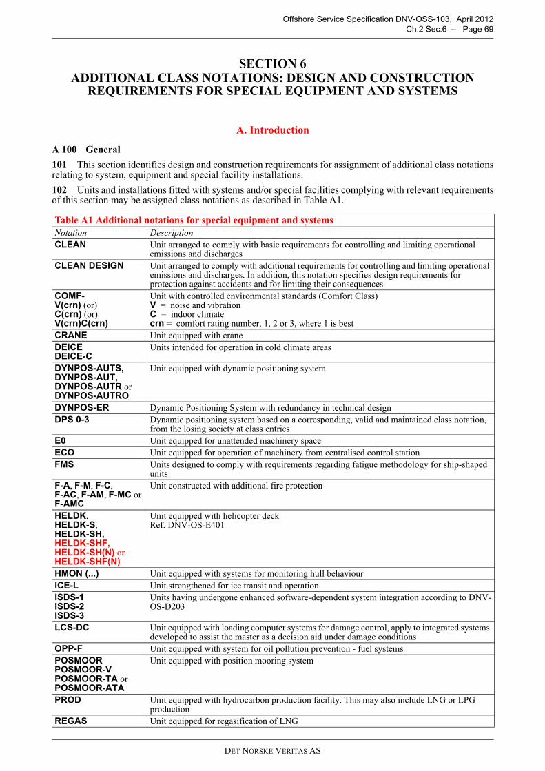
Offshore Service Specification DNV-OSS-103, April 2012Ch.2 Sec.6 – Page 69
SECTION 6ADDITIONAL CLASS NOTATIONS: DESIGN AND CONSTRUCTION
REQUIREMENTS FOR SPECIAL EQUIPMENT AND SYSTEMS
A. Introduction
A 100 General
101 This section identifies design and construction requirements for assignment of additional class notationsrelating to system, equipment and special facility installations.
102 Units and installations fitted with systems and/or special facilities complying with relevant requirementsof this section may be assigned class notations as described in Table A1.
Table A1 Additional notations for special equipment and systemsNotation DescriptionCLEAN Unit arranged to comply with basic requirements for controlling and limiting operational
emissions and dischargesCLEAN DESIGN Unit arranged to comply with additional requirements for controlling and limiting operational
emissions and discharges. In addition, this notation specifies design requirements for protection against accidents and for limiting their consequences
COMF-V(crn) (or) C(crn) (or) V(crn)C(crn)
Unit with controlled environmental standards (Comfort Class)V = noise and vibrationC = indoor climatecrn = comfort rating number, 1, 2 or 3, where 1 is best
CRANE Unit equipped with craneDEICEDEICE-C
Units intended for operation in cold climate areas
DYNPOS-AUTS,DYNPOS-AUT,DYNPOS-AUTR or DYNPOS-AUTRO
Unit equipped with dynamic positioning system
DYNPOS-ER Dynamic Positioning System with redundancy in technical designDPS 0-3 Dynamic positioning system based on a corresponding, valid and maintained class notation,
from the losing society at class entriesE0 Unit equipped for unattended machinery spaceECO Unit equipped for operation of machinery from centralised control stationFMS Units designed to comply with requirements regarding fatigue methodology for ship-shaped
units F-A, F-M, F-C, F-AC, F-AM, F-MC or F-AMC
Unit constructed with additional fire protection
HELDK, HELDK-S, HELDK-SH,HELDK-SHF, HELDK-SH(N) or HELDK-SHF(N)
Unit equipped with helicopter deckRef. DNV-OS-E401
HMON (...) Unit equipped with systems for monitoring hull behaviourICE-L Unit strengthened for ice transit and operation ISDS-1ISDS-2ISDS-3
Units having undergone enhanced software-dependent system integration according to DNV-OS-D203
LCS-DC Unit equipped with loading computer systems for damage control, apply to integrated systems developed to assist the master as a decision aid under damage conditions
OPP-F Unit equipped with system for oil pollution prevention - fuel systemsPOSMOOR POSMOOR-VPOSMOOR-TA or POSMOOR-ATA
Unit equipped with position mooring system
PROD Unit equipped with hydrocarbon production facility. This may also include LNG or LPG production
REGAS Unit equipped for regasification of LNG
DET NORSKE VERITAS AS

Offshore Service Specification DNV-OSS-103, April 2012Ch.2 Sec.6 – Page 70
A 200 Technical reference documents
201 Technical requirements are given by reference to selected:
— DNV offshore standards— DNV recommended practices— other DNV rules and standards— internationally recognised codes and standards.
202 The technical reference documents, which shall be applied, are given in the following subsections andsummarised in Table U1.
A 300 General assumptions
301 DNV may accept alternative solutions found to represent an overall safety level equivalent to that statedin the requirements of this document or referred standards.
302 The requirements stated in this section for additional class notations shall be regarded as supplementaryto those given for assignment of main class and relevant service notations.
B. Position Mooring System
B 100 General
101 POSMOOR notation may be assigned to units fitted with single or spread point mooring systems inaccordance with the requirements of this section.
102 The notation is complemented with the symbols -V, -TA or -ATA as described in Table B1.
103 The notations aim to cover the reliability of the mooring system and equipment, for the purpose ofensuring safe position mooring, and covers the following aspects:
— environmental conditions and loads
SBM Management of safety and environment protection in operationSPM Single point mooringVCS-1VCS-2 VCS-3
Unit equipped with system for control of vapour emission from cargo tanks
VIBR Unit equipped to meet specified vibration level criteria measured at pre-defined positions for machinery, components, equipment and structure
Table A2 Special feature notationsNotation DescriptionBIS Ship-shaped units built for in-water survey of the bottom and related itemsCOAT-1COAT-2
Specification of corrosion prevention in ballast tanks
NON SELF- PROPELLED
A unit for which towing assistance will be required during transit
RECYCLABLE Inventory of Hazardous Materials which addresses prohibited and restricted materials used, and quantifies and locates hazardous materials onboard units which are known to represent a potential hazard to people and the environment(ref. IMO Hong Kong International Convention for the Safe and Environmentally Sound Recycling of Ships)
SUB Strengthened for operation when resting on seabedTMON Tailshaft condition monitoring arrangement
Table B1 POSMOOR class notationsNotation DescriptionPOSMOOR Passive position mooring systemPOSMOOR-V Mooring system designed for positioning in vicinity of other structures POSMOOR-TA Thruster assisted mooring system dependent on manual remote thrust control systemPOSMOOR-ATA Thruster assisted mooring system dependent on automatic remote thrust control system
Table A1 Additional notations for special equipment and systems (Continued)Notation Description
DET NORSKE VERITAS AS

Offshore Service Specification DNV-OSS-103, April 2012Ch.2 Sec.6 – Page 71
— mooring system analysis— thruster assisted mooring— mooring equipment— tests.
B 200 Technical requirements
201 The technical requirements of DNV-OS-E301 shall be complied with for assignment of the POSMOORnotations.
202 Alternatively POSMOOR notations may be granted based on compliance with API RP 2SK.
B 300 Certification of materials and components
301 Certification of equipment shall be in accordance with DNV-OS-E301, Ch.3.
C. Dynamic Positioning Systems
C 100 General
101 The following notations may be assigned to units with dynamic positioning systems: DYNPOS-AUTS,DYNPOS-AUT, DYNPOS-AUTR or DYNPOS-AUTRO according to extent of requirements applied.
102 The various notations depend on the DP-system lay-out and configuration as given in Table C1:
103 The dynamic positioning system includes requirements for the following subsystems, control panels andback-up systems which are necessary to dynamically position the unit:
— power system— controller— measuring system— thruster system— remote thrust control— control panels.
C 200 Technical requirements
201 Technical requirements for the dynamic positioning notations shall be in accordance with the Rules forClassification of Ships, Pt.6 Ch.7.
D. Single Point Mooring (SPM)
D 100 General
101 The additional class notation SPM applies to units fitted with equipment enabling them to be moored tosingle point moorings.
102 The requirements cover the parts of OCIMF’s Recommendations for equipment employed in themooring of ships at single point moorings, applicable for ship-shaped offshore units or installations.
D 200 Technical requirements
201 The requirements of the Rules for Classification of Ships, Pt.5 Ch.3 Sec.15, shall be complied with.
Table C1 Dynamic positioning class notationsNotation DescriptionDYNPOS-AUTS Dynamic positioning system without redundancyDYNPOS-AUT Dynamic positioning system with an independent joystick back-up and a position reference
back-upDYNPOS-AUTR Dynamic positioning system with redundancy in technical design and with an independent
joystick back-upDYNPOS-AUTRO Dynamic positioning system with redundancy in technical design and with an independent
joystick back-up. Plus a back-up dynamic positioning control system in an emergency dynamic positioning control centre, designed with physical separation for components that provide redundancy
DET NORSKE VERITAS AS

Offshore Service Specification DNV-OSS-103, April 2012Ch.2 Sec.6 – Page 72
E. Loading computer
E 100 General
101 Units having installed a system integrated systems developed to assist the master as a decision aid whenthe ship has been subjected to damage and consequent flooding may be given the class notation LCS-DC.
The letters are denoting Loading Computer System Damage Control.
E 200 Technical requirements
201 The requirements of the Rules for Classification of Ships Pt.6 Ch.9 Sec.4 shall be complied with asapplicable.
F. Bow Loading
F 100 General
101 The additional notation BOW LOADING applies to units having a bow loading arrangement satisfyingthe requirements of 200.
F 200 Technical requirements
201 The requirements of the Rules for Classification of Ships, Pt.5 Ch.3 Sec.14, shall be complied with asapplicable.
G. Submerged Turret Loading
G 100 General
101 The additional notation STL applies to units or installations having a submerged turret loadingarrangement satisfying the requirements of 200.
G 200 Technical requirements
201 The requirements of the Rules for Classification of Ships, Pt.5 Ch.3 Sec.14, shall be complied with asapplicable.
H. Hydrocarbon Production Plant
H 100 General
101 Units or installations fitted with offshore hydrocarbon production facilities in compliance with DNVrequirements may be assigned class notation PROD.
102 Where the principle product is LNG the class notation PROD (LNG) may be assigned.
103 Where the principle product is LPG the class notation PROD (LPG) may be assigned
104 Where the plant is intended for vaporisation of LNG, the class notation REGAS may be assigned.
H 200 Technical requirements
201 The requirements for production plants are stated in DNV-OS-E201. Regasification plant may bedesigned in accordance with Classification Note 61.3 and relevant parts of DNV-OS-E201.
H 300 Certification of materials and components
301 Procedures and requirements for classification including certification of equipment shall be inaccordance with DNV-OS-E201, Ch.3.
302 Manufacturers of materials, components and equipment for PROD class shall, prior to construction isstarted, provide the Society with evidence of their capability to successfully carry out fabrication with adequatequality.
Guidance note:Evidence may incorporate successful outcome of construction projects of similar nature.
---e-n-d---of---G-u-i-d-a-n-c-e---n-o-t-e---
DET NORSKE VERITAS AS

Offshore Service Specification DNV-OSS-103, April 2012Ch.2 Sec.6 – Page 73
I. Helicopter Decks
I 100 General101 Units fitted with erected landing platforms for helicopters or landing areas arranged directly on decks ortop of deckhouses may be given the class notation HELDK together with qualifiers as defined in Table I1.
102 The application of the different qualifiers is restricted as follows:
— The qualifier H can only be applied together with the qualifier S. — The qualifier F can only be applied together with the qualifiers SH. — The qualifier (N) can only be applied together with qualifiers SH or SHF.
I 200 Technical requirements201 Technical requirements for HELDK shall comply with DNV-OS-E401, Ch.2, as applicable:
— Sec.1 to Sec.4 for notation HELDK— Sec.5 Additional requirements for qualifier S— Sec.6 Additional requirements for qualifier H— Sec.7 Additional requirements for qualifier F
For addition additional requirements for qualifier (N) see OSS-201, Ch.2, Sec.9.
J. Crane Installations
J 100 General101 CRANE notation may be given to units or installations with permanently installed cranes.102 In addition to certification of the crane, the following is covered:
— supporting structure for the crane, (strengthening of deck structure, pedestal etc.)— devices for locking crane in parked position (unit at sea).
J 200 Technical requirements201 The requirements given in the Rules for Classification of Ships, Pt.6 Ch.1 Sec.3, shall be complied withfor assignment of class notation CRANE.
J 300 Certification of materials and components301 Cranes shall be delivered as DNV certified in accordance with the DNV Standard for Certification No.2.22 “Lifting Appliances”. In agreement with the Society the crane may be certified based on otherinternationally recognised standards.
K. Additional Fire Protection
K 100 General101 Units or installations with additional fire safety measures in accommodation spaces, machinery spacesand cargo spaces may be assigned class notations F-A, F-M, F-C, F-AC, F-AM, F-MC or F-AMC.
Table I1 HELDK class notation
Class notation Description Qualifier Description
HELDK Helicopter deck
<none> Structure
S Additional requirements to ship safety.
H Additional requirements to helicopter safety
F Additional requirements to helicopter facilities
(N) Evaluated with respect to requirements for operation on the Norwegian Continental Shelf (NCS)
DET NORSKE VERITAS AS

Offshore Service Specification DNV-OSS-103, April 2012Ch.2 Sec.6 – Page 74
102 The various notations are related to areas subjected to additional fire protection as given in Table K1.
K 200 Technical requirements201 The requirements as stated in the Rules for Classification of Ships, Pt.6 Ch.4, shall be complied with forassignment of the class notations.
L. Winterization, Cold Climate and Ice Notations
L 100 General101 Units designed or strengthened for operation within particular geographical or environmental areasfound to be in accordance with relevant class rule requirements may be assigned a corresponding optional classnotation.Optional class notations related to cold climate service are given in Ch.1 Sec.3 Table B4.
L 200 Operation of column-stabilised units in ice conditions201 GeneralOffshore units strengthened for occasional navigation and operation in waters with light to heavy first year iceconditions in accordance with this sub-section may be assigned class notation ICE-L as described in Table L1.
202 Technical requirements
1) The ice strengthening requirements given in the Rules for Classification of Ships, Pt.5 Ch.1 Sec.3, shall beapplied as far as relevant and practicable.
2) Propeller nozzles and associated shafts and machinery situated more that 5 m below lowest transit waterline(TWL) are not considered affected by ice loads.
203 Documentation in accordance with A400 shall be submitted for review.
M. Hull Monitoring System
M 100 General101 Units or installations equipped with instrumentation system for monitoring hull behaviour in accordancewith the requirements of this section may be assigned class notation HMON (...) as given in Rules forClassification of Ships Pt.6 Ch.11.102 The system will give warning when stress levels and the frequency and magnitude of accelerationsapproach levels which require corrective action.
M 200 Technical requirements201 Assignment of HMON (...) class notation is based on compliance with the Rules for Classification ofShips, Pt.6 Ch.11.
Table K1 Class notations for additional fire protectionNotation DescriptionF-A Accommodation spaceF-M Machinery spaceF-AM Accommodation and machinery spaceF-C Additional fire protection of cargo spaceF-AC Additional fire protection of accommodation and cargo spaceF-MC Additional fire protection of machinery and cargo spaceF-AMC Additional fire protection of accommodation, machinery and cargo space
Table L1 ICE class notationNotation DescriptionICE-L Strengthened for ice condition operation
DET NORSKE VERITAS AS

Offshore Service Specification DNV-OSS-103, April 2012Ch.2 Sec.6 – Page 75
N. Fatigue Methodology for Ship-Shaped Units
N 100 General101 Ship shaped floating production and storage units may be assigned class notation FMS.102 The requirement for FMS notation is an addition to the fatigue strength requirements for classification.The FMS notation has been introduced for owners or operators who require additional fatigue safety by usinga detailed fatigue methodology for the structures, with increased focus of fatigue critical details during newbuilding phase. The increased safety level will reduce the risk of disruption during production due to repair offatigue damage.103 FMS notation is based on minimum 20 year design fatigue life as default. If the design fatigue life isspecified differently, the specified design fatigue life will be included in brackets, e.g. FMS(30). Theenvironmental data for the transit and offshore sites, which form the basis for the design, will be specified inthe “Appendix to the Classification Certificate”.104 The FMS notation covers design, fabrication and operation of the unit. The specific methodology fordesign and fabrication are included in the DNV-RP-C206 “Fatigue Methodology for Offshore Ships”.Inspection in the operational phase will be included in the in-service inspection program (IIP). The IIP can bebased on a risk based approach.
N 200 Technical requirements201 Assignment of class notation FMS is based on compliance with requirements in DNV-RP-C206.
O. Environmental Notations
O 100 Additional oil pollution prevention measures fuel oil systems101 GeneralUnits arranged and equipped with additional oil pollution prevention measures for the fuel oil system may begiven the class notation OPP-F. 102 Technical requirementsThe requirements given in the Rules for Classification of Ships, Pt.6 Ch.1 Sec.6, shall be complied with forassignment of the class notations.
O 200 CLEAN or CLEAN DESIGN201 GeneralUnits arranged and equipped with the aim to reduce the environmental impact from emissions to air, dischargesto sea, and deliveries to shore from units may be given the additional class notations: CLEAN or CLEANDESIGN.202 Technical requirementsThe requirements given in the Rules for Classification of Ships, Pt.6 Ch.12 Sec.1, shall be complied with forassignment of the class notations.203 DocumentationDrawings, technical information, certificates and operational procedures as specified in the Rules forClassification of Ships Pt.6 Ch.12 Sec.1 C shall be submitted for review.
Guidance note:It should be noted that some of the required documentation is additional to, and different from, documentationnormally considered “Class documentation” as delivered from the newbuilding yard. This is in particular the case foroperational procedures specified in the Rules for Classification of Ships Pt.6 Ch.12 Sec.1 C, Table C2 in that mayrequire input from the owner.
---e-n-d---of---G-u-i-d-a-n-c-e---n-o-t-e---
DET NORSKE VERITAS AS
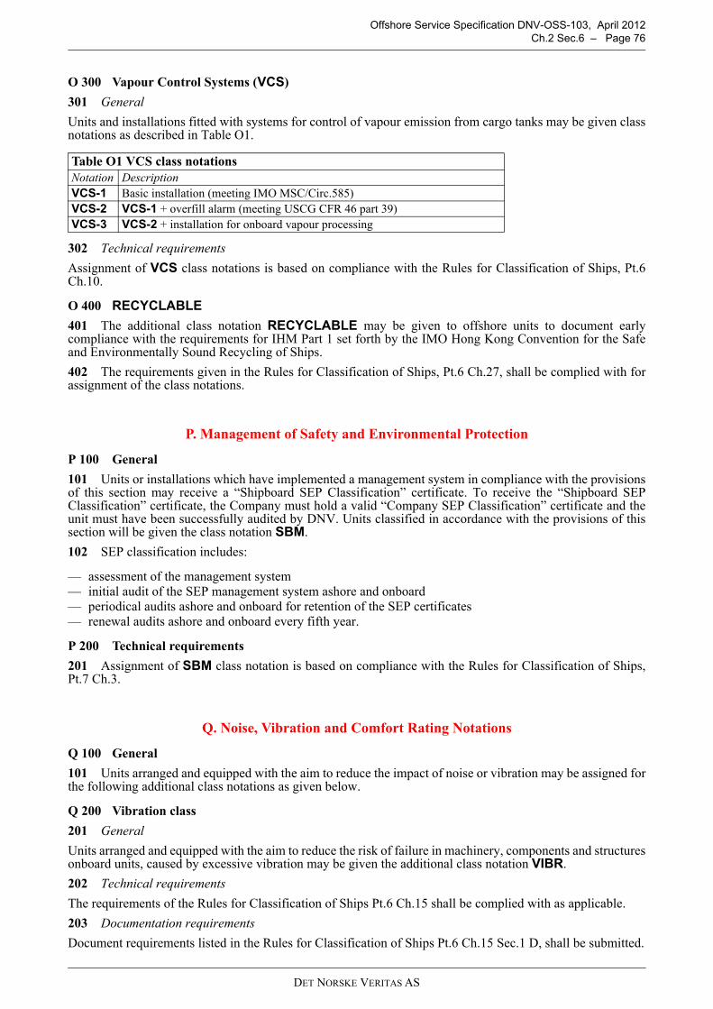
Offshore Service Specification DNV-OSS-103, April 2012Ch.2 Sec.6 – Page 76
O 300 Vapour Control Systems (VCS)
301 General
Units and installations fitted with systems for control of vapour emission from cargo tanks may be given classnotations as described in Table O1.
302 Technical requirements
Assignment of VCS class notations is based on compliance with the Rules for Classification of Ships, Pt.6Ch.10.
O 400 RECYCLABLE
401 The additional class notation RECYCLABLE may be given to offshore units to document earlycompliance with the requirements for IHM Part 1 set forth by the IMO Hong Kong Convention for the Safeand Environmentally Sound Recycling of Ships.
402 The requirements given in the Rules for Classification of Ships, Pt.6 Ch.27, shall be complied with forassignment of the class notations.
P. Management of Safety and Environmental Protection
P 100 General
101 Units or installations which have implemented a management system in compliance with the provisionsof this section may receive a “Shipboard SEP Classification” certificate. To receive the “Shipboard SEPClassification” certificate, the Company must hold a valid “Company SEP Classification” certificate and theunit must have been successfully audited by DNV. Units classified in accordance with the provisions of thissection will be given the class notation SBM.
102 SEP classification includes:
— assessment of the management system — initial audit of the SEP management system ashore and onboard— periodical audits ashore and onboard for retention of the SEP certificates— renewal audits ashore and onboard every fifth year.
P 200 Technical requirements
201 Assignment of SBM class notation is based on compliance with the Rules for Classification of Ships,Pt.7 Ch.3.
Q. Noise, Vibration and Comfort Rating Notations
Q 100 General
101 Units arranged and equipped with the aim to reduce the impact of noise or vibration may be assigned forthe following additional class notations as given below.
Q 200 Vibration class
201 General
Units arranged and equipped with the aim to reduce the risk of failure in machinery, components and structuresonboard units, caused by excessive vibration may be given the additional class notation VIBR.
202 Technical requirements
The requirements of the Rules for Classification of Ships Pt.6 Ch.15 shall be complied with as applicable.
203 Documentation requirements
Document requirements listed in the Rules for Classification of Ships Pt.6 Ch.15 Sec.1 D, shall be submitted.
Table O1 VCS class notationsNotation DescriptionVCS-1 Basic installation (meeting IMO MSC/Circ.585)VCS-2 VCS-1 + overfill alarm (meeting USCG CFR 46 part 39)VCS-3 VCS-2 + installation for onboard vapour processing
DET NORSKE VERITAS AS

Offshore Service Specification DNV-OSS-103, April 2012Ch.2 Sec.6 – Page 77
Q 300 Comfort class
301 General
Units arranged and equipped with the aim to reduce the impact of noise and vibration related to comfort onboard may be assigned for the following additional class notations:
— COMF-V(crn), where crn is a comfort rating number which quantifies the comfort rating of noise andvibration for the unit
— COMF-C(crn), where crn is a comfort rating number which quantifies the comfort rating of the indoorclimate for the unit, or
— COMF-V(crn)C(crn).
302 Technical requirements
The requirements of the Rules for Classification of Ships Pt.5 Ch.12 shall be complied with as applicable.
R. Integrated Software-dependent Systems.
R 100 General
101 Units built and tested in compliance with the requirements of DNV-OS-D203 may be assigned one ofthe optional class notations for integrated software-dependent systems shown in Table R1.
S. Special Feature Notations
S 100 General
101 Special feature notations provide information regarding special design assumptions, arrangements orequipment which is not covered by other class notations. Requirements related to special feature notationscurrently in use are described in this subsection.
S 200 Special feature notation SUB
201 SUB is applicable for column-stabilised units or installations strengthened for operating when resting onthe seabed.
202 Requirements for air gap, safety against overturning stability, local reinforcement of bottom of pontoons,etc. will be specially considered for the “resting on seabed” condition.
S 300 Special feature notation HOT (…°C)
301 This notation applies to storage units or installations intended to carry liquid cargo at a temperaturehigher than 80ºC at atmospheric pressure.
302 The technical requirements in the Rules for Classification of Ships, Pt.3 Ch.1 Sec.14, are to be compliedwith.
S 400 Special feature notation COAT-1 and COAT-2
401 This notation specifies additional requirements for corrosion prevention of tanks.
402 The technical requirements in the Rules for Classification of Ships, Pt.3 Ch.1 Sec.15.
S 500 Tailshaft monitoring - TMON
501 When the following design requirements are fulfilled, the class notation TMON (tailshaft conditionmonitoring survey arrangement) may be obtained:
— the stern tube bearings are oil lubricated— high temperature alarm is fitted on aft stern tube bearing (2 sensors or one easily interchangeable sensor
located in the bearing metal near the surface, in way of the area of highest load, which normally will be thebottom area (5 to 7 o'clock) in the aft third of the bearing)
— where one interchangeable sensor is fitted one spare sensor is to be stored on board— the setting of the stern tube high temperature alarm is normally not to exceed 65°C. Higher alarm set point
may be accepted upon special consideration— the sealing rings in the stern tube sealing box must be replaceable without shaft withdrawal or removal of
propeller
Table R1 ISDS Class notations ISDS[system1,...,system n] Units having undergone enhanced software-dependent system integration for the
system(s) according to DNV-OS-D203.
DET NORSKE VERITAS AS
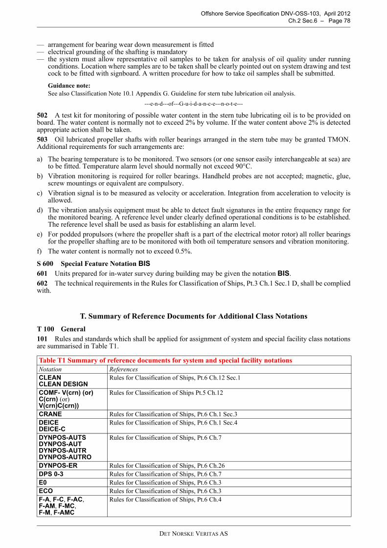
Offshore Service Specification DNV-OSS-103, April 2012Ch.2 Sec.6 – Page 78
— arrangement for bearing wear down measurement is fitted— electrical grounding of the shafting is mandatory— the system must allow representative oil samples to be taken for analysis of oil quality under running
conditions. Location where samples are to be taken shall be clearly pointed out on system drawing and testcock to be fitted with signboard. A written procedure for how to take oil samples shall be submitted.
Guidance note:See also Classification Note 10.1 Appendix G. Guideline for stern tube lubrication oil analysis.
---e-n-d---of---G-u-i-d-a-n-c-e---n-o-t-e---
502 A test kit for monitoring of possible water content in the stern tube lubricating oil is to be provided onboard. The water content is normally not to exceed 2% by volume. If the water content above 2% is detectedappropriate action shall be taken.503 Oil lubricated propeller shafts with roller bearings arranged in the stern tube may be granted TMON.Additional requirements for such arrangements are:
a) The bearing temperature is to be monitored. Two sensors (or one sensor easily interchangeable at sea) areto be fitted. Temperature alarm level should normally not exceed 90°C.
b) Vibration monitoring is required for roller bearings. Handheld probes are not accepted; magnetic, glue,screw mountings or equivalent are compulsory.
c) Vibration signal is to be measured as velocity or acceleration. Integration from acceleration to velocity isallowed.
d) The vibration analysis equipment must be able to detect fault signatures in the entire frequency range forthe monitored bearing. A reference level under clearly defined operational conditions is to be established.The reference level shall be used as basis for establishing an alarm level.
e) For podded propulsors (where the propeller shaft is a part of the electrical motor rotor) all roller bearingsfor the propeller shafting are to be monitored with both oil temperature sensors and vibration monitoring.
f) The water content is normally not to exceed 0.5%.
S 600 Special Feature Notation BIS 601 Units prepared for in-water survey during building may be given the notation BIS.602 The technical requirements in the Rules for Classification of Ships, Pt.3 Ch.1 Sec.1 D, shall be compliedwith.
T. Summary of Reference Documents for Additional Class Notations
T 100 General101 Rules and standards which shall be applied for assignment of system and special facility class notationsare summarised in Table T1.
Table T1 Summary of reference documents for system and special facility notationsNotation ReferencesCLEANCLEAN DESIGN
Rules for Classification of Ships, Pt.6 Ch.12 Sec.1
COMF- V(crn) (or) C(crn) (or) V(crn)C(crn))
Rules for Classification of Ships Pt.5 Ch.12
CRANE Rules for Classification of Ships, Pt.6 Ch.1 Sec.3DEICEDEICE-C
Rules for Classification of Ships, Pt.6 Ch.1 Sec.4
DYNPOS-AUTSDYNPOS-AUTDYNPOS-AUTRDYNPOS-AUTRO
Rules for Classification of Ships, Pt.6 Ch.7
DYNPOS-ER Rules for Classification of Ships, Pt.6 Ch.26DPS 0-3 Rules for Classification of Ships, Pt.6 Ch.7E0 Rules for Classification of Ships, Pt.6 Ch.3ECO Rules for Classification of Ships, Pt.6 Ch.3F-A, F-C, F-AC, F-AM, F-MC,F-M, F-AMC
Rules for Classification of Ships, Pt.6 Ch.4
DET NORSKE VERITAS AS
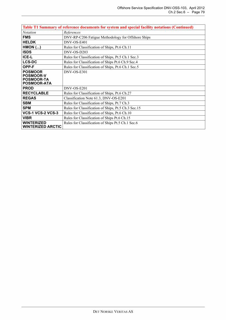
Offshore Service Specification DNV-OSS-103, April 2012Ch.2 Sec.6 – Page 79
FMS DNV-RP-C206 Fatigue Methodology for Offshore ShipsHELDK DNV-OS-E401 HMON (...) Rules for Classification of Ships, Pt.6 Ch.11ISDS DNV-OS-D203ICE-L Rules for Classification of Ships, Pt.5 Ch.1 Sec.3LCS-DC Rules for Classification of Ships Pt.6 Ch.9 Sec.4OPP-F Rules for Classification of Ships, Pt.6 Ch.1 Sec.5POSMOORPOSMOOR-VPOSMOOR-TAPOSMOOR-ATA
DNV-OS-E301
PROD DNV-OS-E201RECYCLABLE Rules for Classification of Ships, Pt.6 Ch.27REGAS Classification Note 61.3, DNV-OS-E201SBM Rules for Classification of Ships, Pt.7 Ch.3SPM Rules for Classification of Ships, Pt.5 Ch.3 Sec.15VCS-1 VCS-2 VCS-3 Rules for Classification of Ships, Pt.6 Ch.10VIBR Rules for Classification of Ships Pt.6 Ch.15WINTERIZEDWINTERIZED ARCTIC
Rules for Classification of Ships Pt.5 Ch.1 Sec.6
Table T1 Summary of reference documents for system and special facility notations (Continued)Notation References
DET NORSKE VERITAS AS

OFFSHORE SERVICE SPECIFICATIONDNV-OSS-103
RULES FOR CLASSIFICATION OF FLOATING LNG/LPGPRODUCTION, STORAGE AND LOADING UNITS
CHAPTER 3
CLASSIFICATION IN OPERATION
CONTENTS PAGE
Sec. 1 General Provisions for Periodical Surveys ........................................................................ 81Sec. 2 General Requirements for Hull and Machinery Surveys................................................... 87Sec. 3 Alternative Survey Arrangements and Surveys Performed by Approved Companies ...... 92Sec. 4 Periodical Survey Extent for Main Class........................................................................... 95Sec. 5 Periodical Survey Extent for Additional Service Notations ............................................ 111Sec. 6 Periodical Survey Extent for Additional Class;
Special Equipment and System Notations ....................................................................... 114Sec. 7 Machinery Alternative Survey Arrangements ................................................................. 129App. A Special Considerations for Conversions .......................................................................... 144App. B Introduction to Offshore Classification ........................................................................... 148
DET NORSKE VERITAS AS

Offshore Service Specification DNV-OSS-103, April 2012Ch.3 Sec.1 – Page 81
SECTION 1GENERAL PROVISIONS FOR PERIODICAL SURVEYS
A. General
A 100 Introduction
101 This section states the periodical survey principles and requirements for retention of class to objectscovered by the provisions of DNV-OSS-103. Requirements are applicable for main class, service notations andadditional class notations unless otherwise stated.
102 The extent of periodical surveying is presented in Sec.4 for main class, Sec.5 for additional servicenotations and Sec.6 for additional system and facility notations.
103 Ship-shaped offshore structures are generally treated as ships with respect to survey of hull andequipment. Exceptions are noted in respective survey requirements.
104 A Memo to Owner (MO) shall be issued stating approved changes to survey procedures and acceptancecriteria, if any. Technical basis for approved changes shall be stated.
105 For column-stabilised and self-elevating units, DNV will develop and maintain an in-service inspectionprogram (IIP) which will contain the structural items to be surveyed to satisfy the requirements of main class,excluding any additional class notations. The IIP constitutes the formal basis for surveying structural itemsunder main class and shall be completed to the satisfaction of attending surveyor before renewal survey can becredited.
106 It is provided that every unit have implemented a maintenance system including machinery system andequipment subject to class (see Sec.7 Table A1). The maintenance system shall ensure that:
— inspections and maintenance are carried out at defined intervals— records of these activities are maintained.
Guidance note:
The maintenance system may be manual or computerised.
---e-n-d---of---G-u-i-d-a-n-c-e---n-o-t-e---
A 200 Survey pre-planning and record keeping
(IACS UR Z15)
201 A specific survey program for renewal surveys and continuous surveys must be worked out in advanceof the renewal survey by the owner in cooperation with the classification society. The survey program shall bein written format. The IIP may be part of the program.
202 Plans and procedures for dry-docking surveys (or underwater inspection in lieu of dry-docking surveyare to be submitted for review in advance of the survey and made available on board. These should includedrawings or forms for identifying the areas to be surveyed, the extent of hull cleaning, non-destructive testinglocations (including NDT methods), nomenclature, and for the recording of any damage or deterioration found.Submitted data, after review by the Society, will be subject to revision if found to be necessary in light ofexperience.
A 300 Accessibility and facilities for surveys on location
301 Annual and special surveys may be carried out on location based on approved procedures outlined in amaintenance system and survey arrangement, without interrupting the function of the unit or installation.
See Ch.2 Sec.3 I for matters which will be taken into consideration for acceptance of surveys to be carried outon location.
B. Periodical Surveys
B 100 General
101 All units shall be subjected to periodical surveys in accordance with requirements of this chapter in orderto confirm that the hull, machinery, equipment and systems remain in satisfactory condition and in compliancewith approval or accepted standards.
DET NORSKE VERITAS AS

Offshore Service Specification DNV-OSS-103, April 2012Ch.3 Sec.1 – Page 82
102 Periodical surveys will belong to one of the following categories according to the level of surveyrequirements:
— annual survey— intermediate survey— complete survey.
The survey required in conjunction with issuance of a new class certificate is denoted:
— renewal survey.
The following specific surveys may be scheduled according to one or more of the above categories:
— bottom survey— propulsion/positioning thruster survey— boiler survey (including steam generator survey)— thermal oil heater survey— survey of optional class notations (voluntary class notations).
103 Periodical surveys shall be carried out at prescribed intervals and within applicable time windows.
A survey may be split in different parts, commenced and progressed within the time window provided all therequirements of the survey are completed by the end of the time window.
The main class intermediate survey can not serve as commencement of the next renewal survey. For concurrentsurveys, the time window may be limited by that of the other survey.
104 The due date of a periodical survey will be established depending upon the survey interval, measuredfrom one of the following events, whichever is relevant:
— date of class assignment— date of commissioning— due date of the previous corresponding survey— date of completion of the previous corresponding survey— date of completion of a major conversion.
A survey may be commenced prior to the defined time window at owner's request. In such a case the due dateof subsequent surveys will be adjusted accordingly.
105 The scope of survey may be extended when compliance with applicable Rules can not be satisfactorilyconfirmed based on extent of surveys as given, or when the surveyor suspects that the ship is not maintainedor handled in accordance with the basis for retention of class.
106 Where substantial corrosion is found, additional thickness measurements shall be taken to confirm theextent of substantial corrosion.
B 200 Postponement of periodical surveys
201 Except for annual and intermediate surveys for main class, the Society may accept to postpone periodicalsurveys in exceptional circumstances and upon consideration in each separate case.
202 Postponement of a periodical survey shall not exceed 3 months and will not affect the survey's next duedate.
203 Postponement of the renewal survey may be granted only upon the owner's written request. Such arequest shall be received by the Society well in advance of the expiry date of the classification certificate. Apostponement of the renewal survey shall normally be based on satisfactory result from a sighting survey withextent equivalent to a main class annual survey.
B 300 Survey of units out of commission
301 Units which have been out of commission, e.g. laid up, for a period of at least 12 months, shall besurveyed and tested before re-entering service. The extent of the surveys and tests will be considered in eachcase depending upon:
— the time the unit has been out of commission— the maintenance and preservative measures taken during lay-up— the extent of surveys carried out during the time out of commission. As a minimum, a sea trial for function
testing of the machinery installation shall be carried out. All overdue surveys shall be completed prior tore-entering service.
302 During lay-up, units shall be subjected to annual survey.
The extent of the annual survey will be reduced compared to main class annual survey, but shall coverwatertight integrity, bilge system, fire hazard and equipment in use.
DET NORSKE VERITAS AS

Offshore Service Specification DNV-OSS-103, April 2012Ch.3 Sec.1 – Page 83
B 400 Survey Schedules
401 Annual survey schedule is as follows:
— The due date in general corresponds to the anniversary date of the class assignment or the expiry of theprevious classification certificate if different.
— The survey shall normally be carried out within a time window of 3 months on either side of the due date— In case a main class annual survey is commenced prior to the defined time window, the survey must be
completed not more than 6 months after the date of commencement. In such cases the anniversary dates forthe subsequent annual surveys will be advanced, corresponding to a date not later than 3 months after thecommencement of the annual survey just carried out.
— An additional main class annual survey may be required when the anniversary date has been advancedunless the expiry date of the classification certificate is also advanced.
402 Intermediate survey schedule is as follows:
— The due date corresponds to the date 2.5 years before the expiry date of the classification certificate.— The survey shall normally be carried out within a time window of 9 months on either side of the due date.— The main class intermediate survey shall be completed concurrently with the second or third main class
annual survey in each period of the classification certificate.— The same surveys and UTM of tanks or spaces can not be credited towards both intermediate and renewal
survey.
403 Complete surveys are denoted:
— Complete survey (2.5 years), or— Complete survey (5 years).— Complete survey schedule is as follows:— The due date corresponds to 2.5 years, or 5 years.
The survey shall normally be carried out within a time window of 9 months before and 6 months after the duedate.
Survey required to be concurrent with the renewal survey shall be completed no later than at the completion ofthe renewal survey.
404 Renewal survey schedule is as follows:
— The due date is set at 5 years interval and corresponds to the expiry date of the classification certificate.— The survey shall normally be completed within a time window of 3 months before the due date.— The survey may be commenced at the fourth annual survey or between the fourth and fifth annual surveys.— In case the survey is commenced more than 15 months before the expiry date of the classification
certificate, the due date of the survey will be advanced to a date not later than 15 months after thecommencement.
— The renewal survey shall be completed concurrently with the last main class annual survey in each periodof the classification certificate.
— The same surveys and UTM of tanks or spaces can not be credited towards both Intermediate and renewalsurvey.
405 Bottom survey schedule is as follows:
a) The due date is set at intervals in accordance with the following:
— two bottom surveys are required during each five-year period of the classification certificate— the interval between any two successive bottom surveys is in no case to exceed 36 months.
b) The survey shall be carried out on or before the due date.Time window is not applicable.
c) One bottom survey shall be carried out in conjunction with the renewal survey, i.e. not more than 15 monthsprior to the expiry date of the classification certificate.
406 Survey of geared and podded thrusters for propulsion, and all DYNPOS/POSMOOR class notationsare scheduled according to complete survey (5 year). Podded thrusters shall also have an annual survey.
407 Survey intervals should in general be as given in Tables B1 and B2.
DET NORSKE VERITAS AS

Offshore Service Specification DNV-OSS-103, April 2012Ch.3 Sec.1 – Page 84
Table B1 Periodical surveys main class. (For survey extent, see Sec.4)
Main character of class
Survey extent and type (as applicable)Survey
interval, years
Survey time window, (See Fig.1)
RemarksWB
(months)WA
(months)
1A1, OI Hull, machinery and equipment
Renewal 5 3 0 (See B400)
Annual 1 3
Intermediate 2-3
1A1, OI Bottom
1A1
Tailshaft with continuous corrosion resistant metallic liner or shaft of corrosion resistant material or shaft with specially approved protection arrangement
5 6 6
Tailshaft with approved oil sealing glands 5 6 6
May be extended to 10 years provided that an intermediate survey is carried out after 5 years with satisfactory result. May be extended to 15 years provided a tailshaft condition monitoring survey arrangement (TMON) has been granted.
Thruster See Sec.4.G
Auxiliary boiler 2.5 6 6
Steam and steam generator 2.5 6 6
Thermal oil heaters 2.5 6 6
Table B2 Periodical surveys, additional class. (For survey extent, see Sec.5 and Sec.6)
Additional class notation Survey extent and type
Survey interval years
Survey time window See Fig.1
RemarksWB
(months)WA
(months)BOWLOADING Bow loading arrangement, Annual 1 3 3
CLEAN, CLEAN DESIGN Environmental class, Annual 1 3 3
To be carried out concurrently with the annual survey main class.WA is 0 when completed concurrently with the renewal survey main class.
COMF-V(crn) or C(crn) or V(crn)C(crn))
Comfort class, Annual 1 3 3
To be carried out concurrently with the annual survey main class.WA is 0 when completed concurrently with the renewal survey main class.
CRANE Shipboard crane, AnnualShipboard crane, complete periodical
15
33
30
DEICE, DEICE-C De-icing and anti-icing system, Annual 1 3 3
DYNPOS-AUTS, DYNPOS-AUT, DYNPOS-AUTR, DYNPOS-AUTRO
Dynamic positioning, Complete periodical 2.5 6 6
See B400
DET NORSKE VERITAS AS

Offshore Service Specification DNV-OSS-103, April 2012Ch.3 Sec.1 – Page 85
E0, ECO Periodically unattended machinery space
Annual Complete periodical
15
33
3 3
F-A, F-M, F-C, F-AC, F-AM, F-MC, F-AMC
Additional fire protection, Complete periodical 2.5 6 6
See B400
FMS Fatigue methodology for ship-shaped units 5 3 0
HELDK Helicopter deck 5 3 0
HMON (...) Hull monitoring system, Annual 1 3 See B400
ICE-L Strengthened for ice conditions 1 3 3
LCS-DC Loading computer for damage controlLNG (or LPG) LOADING UNIT or LNG (or LPG) LOADING INSTALLATION
AnnualComplete periodical
15
33
30
The surveys will be based upon approved operation manual
LNG (or LPG) PRODUCTION UNIT or LNG (or LPG) PRODUCTION INSTALLATION
Annual Complete periodical
15
33
3 See B400
LNG (or LPG) STORAGE UNIT or LNG (or LPG) STORAGEINSTALLATION
AnnualComplete periodical
15
33
3See B400
OPP-F *) Additional oil pollution prevention measures for fuel oil systems 5 3 0
*) No specific survey items. Complete periodical survey considered covered by renewal survey main class.
POSMOOR Position mooring
AnnualIntermediateComplete periodical
12.55
363
36
See B400
See B400
PROD (LNG) or PROD (LPG) Production plant Annual
Complete periodical15
33
3 See B400
REGASLNG Regasification plant
Annual Complete periodical
15
33
3 See B400
SBMSafety and environmental protection (SEP) management system, Complete periodical
5 3 See B400
SPM Arrangement for single point mooring, Annual 1 3 3
STL Arrangement for submerged turret loading, Complete periodical 5 3 3
TMON Tailshaft monitoring, annual 1 6 6
VCS Vapour control systems, Complete periodical 5 3 See B400
VIBR 1 3 3WINTERIZED (design temp. °C) Operating in cold climate 1 3 3
WINTERIZED ARCTIC (design temp. °C)
Operating in cold climate, with add. req. for pollution prevention in vulnerable arctic areas
1 3 3
Table B2 Periodical surveys, additional class. (For survey extent, see Sec.5 and Sec.6) (Continued)
Additional class notation Survey extent and type
Survey interval years
Survey time window See Fig.1
RemarksWB
(months)WA
(months)
DET NORSKE VERITAS AS
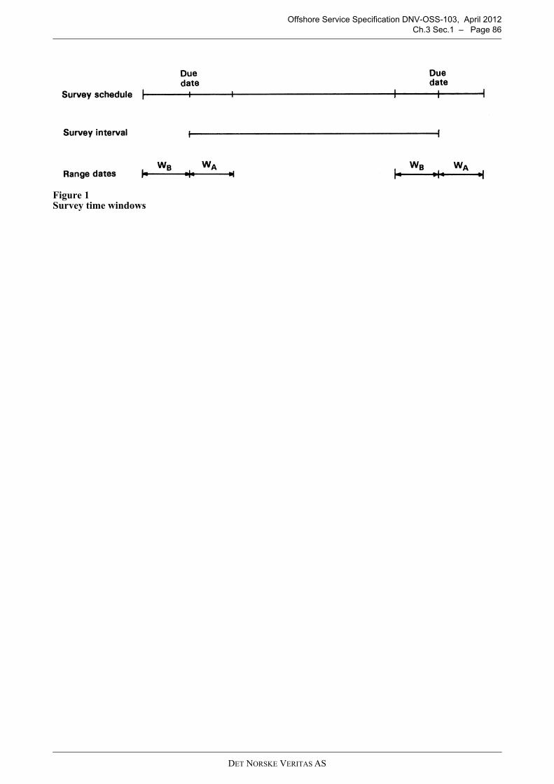
Offshore Service Specification DNV-OSS-103, April 2012Ch.3 Sec.1 – Page 86
Figure 1 Survey time windows
DET NORSKE VERITAS AS

Offshore Service Specification DNV-OSS-103, April 2012Ch.3 Sec.2 – Page 87
SECTION 2GENERAL REQUIREMENTS FOR HULL AND MACHINERY SURVEYS
A. General
A 100 Preparation for survey101 The owner shall provide the necessary facilities for safe execution of surveys.102 Tanks and spaces shall be safe for access, i.e. gas freed, ventilated, cleaned and illuminated.103 For overall and close-up examination, means shall be provided to enable the surveyor to examine thestructure in a safe and practical way, see B100.
B. Requirements for Hull Surveys
B 100 Conditions for survey and access to structures101 In preparation for survey and to allow for a thorough examination, all spaces shall be cleaned includingremoval from surfaces of all loose accumulated corrosion scale. In tanks where soft coatings have been applied,representative areas and those areas where it is obvious that further close-up examination is required shall becleaned free of soft coating.
Guidance note:Spaces should be sufficiently clean and free from water, scale, dirt, oil residues etc. to reveal corrosion, deformation,fractures, damage, or other structural deterioration. However, those areas of structure whose renewal has already beendecided by the owner need only be cleaned and descaled to the extent necessary to determine the limits of the renewedareas. for more detailed information with regard to a tank where soft coatings have been applied, see IACSrecommendation No. 44.
---e-n-d---of---G-u-i-d-a-n-c-e---n-o-t-e---
102 All spaces shall be made safe for access, i.e. gas freed, ventilated and illuminated, and prepared for thesurveyor to examine the structure in a safe and practical way. One or more of the following means for access,acceptable to the surveyor, shall be provided:
— permanent staging and passages through structures— temporary staging and passages through structures— lifts and moveable platforms— hydraulic arm vehicles such as conventional cherry pickers— boats or rafts— portable ladder— other equivalent means.
103 Rafts or boats alone may be allowed for survey of the under deck areas for tanks or spaces, if the depthof the webs is 1.5 m or less.If the depth of the webs is more than 1.5 m, rafts or boats alone may be allowed only:
a) when the coating of the under deck structure is in GOOD condition and there is no evidence of wastage orb) if a permanent means of access is provided in each bay to allow safe entry and exit. This means:
— access direct from the deck via a vertical ladder and a small platform fitted approximately 2 m belowthe deck in each bay or
— access to deck from a longitudinal permanent platform having ladders to deck in each end of the tank.
The platform shall, for the full length of the tank, be arranged in level with, or above, the maximum water levelneeded for rafting of under deck structure. For this purpose, the ullage corresponding to the maximum waterlevel is to be assumed not more than 3 m from the deck plate measured at the midspan of deck transverses andin the middle length of the tank.If neither of the above conditions are met, then staging or “other equivalent means” of access shall be providedfor the survey of the under deck areas.The use of rafts or boats alone does not preclude the use of boats or rafts to move about within a tank during asurvey.
Guidance note:Reference is made to IACS Recommendation No. 39 – Guidelines for the use of Boats or Rafts for Close-up surveys.
---e-n-d---of---G-u-i-d-a-n-c-e---n-o-t-e---
DET NORSKE VERITAS AS

Offshore Service Specification DNV-OSS-103, April 2012Ch.3 Sec.2 – Page 88
Guidance note:Use of remote inspection technique methods to facilitate the required internal examinations, including close-upexaminations and thickness measurements, may be specially considered by the Society. The methods applied shallprovide the information normally obtained from a survey carried out by the surveyor.In order to verify the results, confirmatory close-up examinations and thickness measurements at selected locationsshall be carried out by the surveyor, not using the remote inspection technique method.Proposals for use of remote inspection technique methods shall be submitted to the Society for acceptance in advanceof the survey.
---e-n-d---of---G-u-i-d-a-n-c-e---n-o-t-e---
104 A survey planning meeting shall be held prior to the commencement of any renewal and intermediatesurveys between the attending surveyor(s), the owner's representative in attendance and the thicknessmeasurement / NDT company representative, where involved.
B 200 Survey extent 201 The survey consists of examination, measurements and testing as required for different survey categorieswith the aim to ensure that the hull structure, hull equipment and piping are in satisfactory condition withrespect to corrosion, deformation, fractures, damage or other structural deterioration.
202 When examination or overall examination is required the structure or object is visually examined froma significant distance. In such cases the general maintenance, the condition of protective coating, rust deposits,leakages and structural detachments and damage may be observed and the surveyor may extend the survey asconsidered necessary.203 When close-up examination is specified by the Rules or required by the surveyor the structure or objectis visually examined from a distance normally within reach of hand.Thickness measurements for general assessment and recording of corrosion pattern shall be taken as specifiedby the Rules as part of the survey.
Guidance note:Areas with good coating/original coating intact thickness measurements may be waived. Additional UTM may berequired in other areas where corrosion is observed.
---e-n-d---of---G-u-i-d-a-n-c-e---n-o-t-e---
204 The surveyor may require thickness measurements in any portion of the structure where signs of wastageare evident or in areas where wastage is normally found. The surveyor may extend the scope of the thicknessmeasurements if considered necessary.205 When thickness measurements are specified by the Rules or required by the surveyor the measurementsshall be carried out to an extent sufficient to determine both general and local corrosion levels.Unless carried out by the surveyor himself, thickness measurements shall be carried out by a qualified companyapproved by the Society and witnessed by a surveyor. This requires the surveyor to be on board, while themeasurements are taken, to the extent necessary to control the process.
Where it is required to carry out thickness measurements of structures subject to close-up examination, thesemeasurements shall be carried out simultaneously with the close-up examination.
The surveyor shall review the final thickness measurement report and countersign the cover page.206 Where substantial corrosion, as defined in Ch.3 Sec.4 D207 is found, additional thickness measurementsshall be taken to confirm the extent of substantial corrosion.The additional measurements shall be taken in patterns corresponding to tables given in Sec.4 D depending onship type.These additional thickness measurements shall be carried out before the survey is considered as completed.
207 The examination may be extended also in cases when:
— information is available of defects suffered on similar structure or details in similar tanks/holds or onsimilar ships
— the structure under survey has been approved with reduced scantlings due to an approved corrosion controlsystem.
B 300 Repair of structural damage or deterioration
301 A prompt and thorough repair is a permanent repair completed at the time of survey to the satisfactionof the surveyor, therein removing the need for the imposition of any associated condition of class.
302 Any damage in association with wastage over the allowable limits (including buckling, grooving,detachment or fracture), or extensive areas of wastage over the allowable limits, which affects or, in the opinionof the surveyor, will affect the unit's structural, watertight or weathertight integrity, shall be promptly andthoroughly repaired.
DET NORSKE VERITAS AS

Offshore Service Specification DNV-OSS-103, April 2012Ch.3 Sec.2 – Page 89
303 For locations where adequate repair facilities are not available, consideration may be given to allow theunit to proceed directly to a repair facility. This may require discharging the cargo and or temporary repairs forthe intended voyage.304 Additionally, when a survey results in the identification of significant corrosion or structural defects,either of which, in the opinion of the surveyor, will impair the unit's fitness for continued service, remedialmeasures shall be implemented before the unit continues in service.
C. Requirements for Machinery Surveys
C 100 Maintenance and preparation for survey101 Every unit shall have implemented a maintenance system.The maintenance system shall ensure that:
— inspections and maintenance are carried out at defined intervals— any non-conformity is reported with its possible cause, if known— appropriate corrective action is taken— records of these activities are maintained.
The machinery and systems subject to class shall be maintained in accordance with the maintenance systemimplemented.102 In preparation for survey and to allow for a thorough examination, machinery components and relatedspaces shall be cleaned, including removal from surfaces of loose accumulated corrosion scale, mud and oil-residues. The spaces and components of attention shall have proper access including dismantling as necessary.
C 200 Replacement of Machinery Components201 When machinery components are renewed, such components should in general be delivered inaccordance with requirements as per valid Rules at the time of newbuilding.
Guidance note:For guidance regarding spare parts for units in operation see Rules for Classification of Ships Pt.4 Ch.1 Sec.5 A100.
---e-n-d---of---G-u-i-d-a-n-c-e---n-o-t-e---
C 300 Machinery verification301 If significant repairs are carried out to main or auxiliary machinery, a dock and/or sea trial shall be carriedout as required by the attending surveyor.
Guidance note:
1) Significant repair:
A significant repair is one where the engine is completely dismantled and re-assembled, in cases such as renewalof crankshaft, bedplate, engine entablature renewal. significant repairs will, furthermore, be cases of repairs afterserious damage to the engine after fire or flooding of the engine room resulting from e.g. collision or groundingof the unit.
The following are not defined as significant repairs.
Routine maintenance of the engine; such as:
- unit overhaul (piston, cylinder head, liner)- turbocharger overhaul- bearing inspections- renewal of cracked liners- renewal of cylinder heads- use of new spares parts- use of reconditioned parts- open up and overhaul of units and bearings- welding repair in the thrust bearing ribs.
2) Scope of testing:Main engine:
a) Sea trial: upon complete reassembly after bedplate or crankshaft renewal, testing as for a new engine is required.The service engineer of the manufacturer’s prepared test program should be used by the attending surveyor.
b) Dock trial: generally, the testing should be limited to the following tests, which typically can be carried outalongside:
- start / stop / reversing- local / remote operation- random safety alarms and cut-outs, including emergency stop.
DET NORSKE VERITAS AS

Offshore Service Specification DNV-OSS-103, April 2012Ch.3 Sec.2 – Page 90
Auxiliary engines:Generally, the testing can be done alongside (shipyard or at other wharf), and does not necessarily require a seatrial. Testing as follows is recommended:
- start / stop- local / remote operation- random safety alarms and cut-outs, including over speed and emergency stop- parallel running and load test.
Steering gears:Trial performed alongside is normally sufficient.In certain case (e.g. modifications, insurance and vetting cases) testing at unit’s full speed may be required, forwhich a sea trial will be necessary. Largely handled case by case, calling for surveyor’s experienced assessment.Owners typically will not raise objection related to this issue, and actually are likely to request DNV to attend thesea trial and issue statement thereafter.
---e-n-d---of---G-u-i-d-a-n-c-e---n-o-t-e---
D. Special Provisions for Ageing Units
D 100 General101 Floating Production, Storage and Loading Units with nominal age equal to or higher than documentedfatigue life shall be subject to evaluation for special provisions.102 A fatigue utilisation index (FUI) shall be calculated to characterise units of column-stabilised and self-elevating type. The FUI is defined as the ratio between the effective operational time and the documentedfatigue life.103 Calculation of effective operational time shall be based on recorded operations history. For the purposeof calculating the FUI, the following may be assumed:
— contribution from operation in harsh environment, e.g. North Sea, North Atlantic and Canada, equals actualoperating time in such environment
— contribution from operation in other environments equals one third (1/3) of actual operating time in suchenvironments
— periods of lay-up and yard stay may be disregarded— for self-elevating units; contribution from transit operation.
104 Owner shall submit FUI or historical data allowing for calculation of FUI as part of the planning processprior to renewal survey when the nominal age exceeds the documented fatigue life. 105 Operation of the unit may continue when the FUI exceeds 1.0 provided the required safety level of thevessel is maintained. If no fatigue cracks have been found in a vessel prior to the FUI reaching 1.0, or if anyfindings have been evaluated to have insignificant influence on the fatigue capacity, no special provisions willbe required until such cracks are detected.106 For a vessel with FUI > 1.0 and where cracks have been detected in fatigue sensitive areas, the requiredsafety level is in general considered satisfied either by increasing the inspection frequency (as provided in D200and D300) or by performing a condition based assessment for the vessel, as proposed in the following guidancenotes.
Guidance note:A condition based inspection planning is performed by judging the vessel based on the actual condition rather thanon age in order to maintain the required safety level. In this context a scope according to the following procedureshould be performed:
- Apply the results from a fatigue analysis. The detail level of the analysis will influence the results. Higher detail levelreduces the uncertainties and increases the confidence in the results and hence reduce the inspection frequency.
- Mapping of critical connections w.r.t. fatigue capacity, i.e. ranking of fatigue sensitive details.- Identify details to be modified/upgraded w.r.t. fatigue strength.- Determine required safety level – dependent on consequence and access for inspection- Apply the fatigue results in a risk based analysis (RBI) including historical data from inspections/findings and
inspection quality for preparing the inspection program.- Perform a continuous updating of the inspection plan based on inspection results.The inspection plan obtained from on a condition based approach is highly dependent on the confidence level of theparameters considered. Less confidence increases the probability of failure (PoF) and hence the inspection frequencywill increase.
---e-n-d---of---G-u-i-d-a-n-c-e---n-o-t-e---
107 The Society will issue a MO (Memo to Owner) stating the FUI and agreed compensating measures (seealso D200 and D300) prior to the renewal survey for the 5-year period in which the FUI exceeds 1.0.
DET NORSKE VERITAS AS

Offshore Service Specification DNV-OSS-103, April 2012Ch.3 Sec.2 – Page 91
108 The special provisions for maintaining required safety level focus on the fatigue and corrosionproperties of the hull and supporting structure. Degradation mechanisms due to ageing effects related to otheraspects such as marine systems must also be given due consideration by owner through maintenance, and byDNV surveyors through regular surveys.
109 Associated plans and procedures, i.e. condition based inspection plans applying risk based approach,shall be approved by the Society. The scope of the improvement program will depend on the initial assessmentand owner's plans for further use of the unit.
110 Units which have undergone an assessment and improvement program as outlined above to the Society'ssatisfaction, will be surveyed based on the modified inspection program.
111 When the FUI exceeds 1.0, systematic thickness measurements shall be performed at renewal surveysas specified in Ch.3 Sec.4 D208. Owner shall submit a program for such measurements for approval prior tothe renewal survey.
112 Owner shall document that the corrosion protection of the unit's hull is adequate and in line withconditions assumed in original design when the FUI exceeds 1.0. The corrosion protection system is to bespecially surveyed.
D 200 Column-stabilised units
201 If fatigue cracks have been found in a unit prior to the FUI reaching 1.0, and the findings are locatedwithin fatigue sensitive areas of the unit, the owner shall assess structural details in these areas at latest priorto the renewal survey for the 5-year period in which the FUI will reach 1.0, with the purpose of maintainingthe required safety level for the structure. (i.e. structural modifications for improving the fatigue capacity).
202 The basis for the condition based inspection planning, is documented fatigue lives for the typicalstructural details in combination with the documented as-is condition (inspection history). The procedure asoutlined in D106 is to be followed. A ranking of details starting with the lowest fatigue lives may convenientlybe established See requirements for high level analysis in DNV-OS-C103 Appendix B.
203 Units with FUI > 1.0, previous cracks located in fatigue sensitive areas and which have not beensubjected to an assessment for documenting the condition of the unit, shall be subject to additional NDE atintermediate surveys corresponding to the extent required for renewal survey.
204 The process outlined in 201through 203shall be repeated prior to each successive renewal survey afterthe FUI has reached 1.0 or after the renewal survey then a condition based inspection plan is established.
205 Units with a watertight underwater bracing system, shall have an approved leak detection systemaccording to guidelines issued by the Society.
206 Areas identified for leak detection shall be examined for leaks at least twice monthly when the FUIexceeds 1.0. This is to be confirmed at the annual survey.
D 300 Self-elevating units
301 For the self-elevating units FUIs may be calculated separately and in detail for various parts of the unitsuch as leg nodes, spud cans, jacking gear house and deck structure. The calculations may reflect the variousdegrees of bottom restraints and loading pattern resulting from the deck being fixed at various levels during theoperations history of the unit.
Based on the above calculation a condition based approach, as outlined in D105 above, can be applied for theinspection planning.
Guidance note:The condition based inspection planning can be based on a high level, refined, fatigue analysis as proposed in DNV-RP-C203.
---e-n-d---of---G-u-i-d-a-n-c-e---n-o-t-e---
302 If the condition based approach as outlined in D105 and D301 above is not considered, the inspectionscope is to be increased. In addition to the standard scope of survey outlined in B200, 5% of the areas with FUIexceeding 1.0 shall be subject to NDE at renewal surveys.
303 The additional areas for NDE shall be selected with focus on probability of cracking and consequence ofpossible failures.
304 When operational time (time in operation regardless of environment excluding periods of lay-up andyard-stay) exceed documented fatigue life, the scope for survey of jacking gears as outlined in Sec.4 D209 shallincrease to comprise about 20% of jacking gear units but not less than two units per leg.
D 400 Ship-shaped units
401 Extended survey requirements for ageing units of ship-shaped type with service notation storage unit arecondition-based as per Sec.4 B201.
402 No special provisions are enforced for other service notations.
DET NORSKE VERITAS AS

Offshore Service Specification DNV-OSS-103, April 2012Ch.3 Sec.3 – Page 92
SECTION 3ALTERNATIVE SURVEY ARRANGEMENTS AND SURVEYS
PERFORMED BY APPROVED COMPANIES
A. Alternative Survey Arrangements
A 100 General overview of survey arrangements
101 Alternative survey arrangements may be accepted as an option to applicable periodical surveys for mainclass.
102 The following survey arrangements may be granted upon written request from the owner:
— Hull continuous, a survey arrangement that includes all the unit's hull compartments and structure.— Hull PMS (Planned Maintenance Systems)— Machinery continuous, a survey arrangement based on surveys of the machinery items as detailed in Sec.7
C.— Machinery PMS, a survey arrangement based on a planned maintenance system. The requirements are
detailed in Sec.7 D.— Machinery CM, a survey arrangement that can include selected parts of the machinery, and is not covering
the complete machinery installation onboard. the requirements are detailed in Sec.7 E.— PMS RCM, a survey arrangement based on review of the company management, the RCM analysis and the
implemented maintenance system. The requirements are detailed in Sec.7 G.— Offshore CM (condition monitoring).
A 200 Hull PMS (Planned Maintenance System)
201 Hull PMS is a survey arrangement offered as an integral part of classification compliance for the hullstructure through the alignment and integration of classification requirements with an approved andimplemented planned inspection and maintenance system. The system performance and condition of hullstructure and maintenance work carried out shall be verified by the Society during annual survey and inconnection with renewal survey of the unit.
202 Hull PMS is applicable for units with survey arrangement Hull Continuous.
203 An initial survey shall be carried out onboard the unit in order to verify that the system has beenimplemented in accordance with the approved documentation and that the system is used as intended. It isrequired that the planned maintenance system has been operated for at least 6 months before the initial surveyis carried out.
204 If the conditions for the survey arrangement are not complied with or in case of change of technicalmanagement of the unit, the survey arrangement will be cancelled and substituted by Hull Continuous surveyarrangement.
A 300 Survey arrangement based on Reliability Centred Maintenance (RCM) system
301 A planned maintenance system based on RCM may be accepted by the Society. An approved plannedmaintenance system is a pre-requisite for this survey arrangement. Compliance with the relevant requirementsas given in Sec.7 D is therefore necessary, with the exception of the requirements related to maintenanceintervals.
An internationally recognised standard is to be used as a base for the RCM system, e.g. SAE JA1011 and ISO60300-3-11.
302 The following information is to be submitted to the Society for approval:
a) The RCM analysis in paper or electronic form, should include the following:
— methodology used for selecting systems— decision criteria for ranking criticality— standard used as a baseline (e.g. SAE / ISO)— details of the participants in the analysis, with qualifications.
b) The systems and equipment covered by the analysis. Drawings and documentation may be required as necessary.
c) Equipment manufacturers guidelines for minimum maintenance levels.
d) Details regarding implementation of the RCM analysis into the PM system.
e) Methodology for continuous improvement / refinement of RCM system.
DET NORSKE VERITAS AS

Offshore Service Specification DNV-OSS-103, April 2012Ch.3 Sec.3 – Page 93
Guidance note:Typically the following seven steps are to be taken into account for machinery systems covered by the RCMphilosophy:
— what are the system functions and associated performance standards?— how can the system fail to fulfil these functions?— what can cause a functional failure?— what happens when a failure occurs?— what effect or consequences will a failure have?— what can be done to detect and prevent the failure?— what should be done if a maintenance or proactive task cannot be found?
---e-n-d---of---G-u-i-d-a-n-c-e---n-o-t-e---
303 If condition monitoring of equipment is to be carried out as part of the RCM system, this is to be carriedout in accordance with an approved programme. See DNV classification note 10.2 for further details. Conditionmonitoring of equipment will normally be approved on an individual equipment basis.304 An implementation survey onboard the vessel is required in order to verify that the RCM analysis isproperly implemented into the pm system onboard. It is recommended that the system has been implementedand operated for at least 6 months before the implementation survey is carried out. In order to verify the system and the crew’s general knowledge, the implementation survey is to be carried outduring normal operation. On a successful implementation survey, a certificate for machinery RCM will beissued stating conditions for the survey arrangement and the machinery included in the arrangement.305 To maintain the validity of the survey arrangement machinery RCM, an annual survey of theimplemented system is required. This survey replaces the annual and renewal surveys of machinery forcomponents included in the RCM system. The purpose of this survey is to review and evaluate the previousperiod's maintenance activities and experience.The annual survey shall normally consist of examination of:
— condition monitoring records— maintenance records— assessment of RCM handling onboard— verification that the spares required to be held onboard is in place.
If found necessary by the surveyor, opening or testing of machinery may be required.306 To prolong the validity of the survey arrangement a renewal survey of the implemented RCM systemduring normal operation is required. The purpose of this survey is to verify that:
— procedures for carrying out RCM are followed— the vessel’s crew are familiar with system and handling of results— re-evaluation of maintenance schedules as required.
307 Any modifications to equipment or machinery systems which could impact the RCM system must bedocumented and forwarded to the Society for approval.
B. Surveys by Approved Companies or Service Suppliers
B 100 General101 Parts of the periodical surveys may be carried out by companies approved by DNV. The following surveyparts may be performed by such companies:
— thickness measurements— bottom survey afloat— general NDT— mooring line survey.
B 200 Thickness measurements201 Thickness measurements as part of the periodical surveys shall be carried out by a qualified companyapproved by the Society unless carried out by the surveyor himself.202 Thickness measurements shall normally be carried out by means of ultrasonic test equipment. Theaccuracy of the equipment shall be proven to the surveyor as required.203 A thickness measurement report shall be prepared. The report shall give the location of themeasurements, the thickness measured and the corresponding original thickness. Furthermore, the report shallgive the date when the measurements were carried out, type of measuring equipment, names of personnel andtheir qualifications. The report shall be signed by the operator.
DET NORSKE VERITAS AS

Offshore Service Specification DNV-OSS-103, April 2012Ch.3 Sec.3 – Page 94
B 300 Bottom survey afloat301 An approved company to be used. The results of the survey are to be verified by a DNV surveyor.
B 400 Non-destructive testing 401 Non-destructive testing as part of the periodical surveys shall be carried out by a qualified companyapproved by the Society.
Guidance note:For more information, see Standard for Certification No. 2.9 / Approval Programme No. 402B: “Firms Engaged inNon Destructive Testing (NDT) on Offshore Projects and Offshore Units/Components”.
---e-n-d---of---G-u-i-d-a-n-c-e---n-o-t-e---
B 500 Mooring chain inspections501 Inspection of mooring lines as part of the periodical surveys shall be carried out by a qualified companyapproved by the Society.
Guidance note:For more information, see Standard for Certification No. 2.9 / Approval Programme No. 413: “Service SuppliersEngaged in Renewal Survey Examination of Mooring Chain Intended for Mobile Offshore Units”.
---e-n-d---of---G-u-i-d-a-n-c-e---n-o-t-e---
B 600 Condition monitoring601 Condition monitoring as part of DNV’s periodical surveys of machinery and equipment can be carriedout by a qualified company approved by the Society. This minimizes the requirement to oversee the conditionmonitoring onboard each individual offshore installation.
Guidance note:For more information, see Approval Programme “Service Suppliers Engaged in condition monitoring of machineryonboard. Also see Sec.7 in this chapter.
---e-n-d---of---G-u-i-d-a-n-c-e---n-o-t-e---
DET NORSKE VERITAS AS

Offshore Service Specification DNV-OSS-103, April 2012Ch.3 Sec.4 – Page 95
SECTION 4PERIODICAL SURVEY EXTENT FOR MAIN CLASS
A. General
A 100 Introduction
101 This section presents the standard extent of surveys for retention of main class 1A1 for mobile offshoreunits and OI for floating offshore installations.
102 The requirements for service notations are given in Sec.5, and additional system and special facility classnotations are given in Sec.6.
103 Subsections for tailshaft (F) and thrusters for propulsion (G) are not applicable for OI class.
A 200 Hull survey - general
201 Conditions of protective coating
Where provided, the condition of protective coating of cargo holds, cargo tanks and ballast tanks shall beexamined.
The condition will be rated GOOD, FAIR or POOR as defined in Table A1.
202 For structures where original protective coatings are in GOOD condition, the extent of close-upexamination and thickness measurements may be specially considered. This also applies to tanks of stainlesssteel. If not otherwise specified, the same applies for re-coated structures (by epoxy coating or equivalent,alternatively a type approved coating, e.g. semi-hard), provided that the condition of the protective coating isin GOOD condition and that documentation is available stating that:
— the scantlings were assessed and found satisfactory by a surveyor prior to re-coating— the coating was applied according to the manufacturer's recommendations.
Special consideration as used in this context is taken to mean, as a minimum, that sufficient close-upexamination and thickness measurements are carried out to confirm the actual average condition of thestructure under the protective coating.
A 300 Extent of hull survey
301 The In-service Inspection Program (IIP) for units of column-stabilised and self-elevating types (see Sec.1A105) is developed on the basis of a general, experience-based scope in combination with design andfabrication particulars for the actual unit as well as experience from in-service surveys of units of similar type.
302 The basic scope for development of IIP for units of column-stabilised type is given in Table A2.
303 The basic scope for development of IIP for units of self-elevating type is as given in Table A3.
304 Relevant survey requirements for units of ship-shaped types additional to those stated in the Rules forClassification of Ships are summarised in Table A4.
305 The extent of examination specified in the tables A2 to A4 may be modified based on designdocumentation evaluation, inspection results / crack history and experience with similar units /details.
306 The extent of examination specified in the tables A2 to A4 may be refined by use of RBI / RCMmethodologies.
Table A1 Conditions of protective coatingCorrosion protection system
Is normally to consist of full hard coating supplemented by anodes or full hard coating.
Guidance note:Other coating systems may be considered acceptable as alternatives provided that they areapproved by DNV and applied and maintained in compliance with the manufacturer'sspecification.
---e-n-d---of---G-u-i-d-a-n-c-e---n-o-t-e---
Coating condition “GOOD”
Condition with only minor spot rusting.
Coating condition “FAIR”
Condition with local breakdown at edges of stiffeners and weld connections and/or light rusting over 20% or more of areas under consideration, but less than as defined for POOR condition.
Coating condition “POOR”
Condition with general breakdown of coating over 20% or more of areas or hard scale at 10% or more of areas under consideration.
DET NORSKE VERITAS AS

Offshore Service Specification DNV-OSS-103, April 2012Ch.3 Sec.4 – Page 96
Guidance note:At the 1st Annual or intermediate survey after construction, column-stabilised and self-elevating units may be subjectto examination of major structural components including non-destructive testing, as deemed necessary by the Society.If the Society deems such survey to be necessary, the extent should be agreed to by the Society and the owner orcustomer prior to commencement of the Survey.
Table A2 Column-stabilised Units
Special Areas for Inspection 1) (SP)Connections
TYPE OF SURVEYAS IS RS
INT EXT INT EXT INT EXTV NDT V NDT V NDT V NDT V NDT V NDT
SP1 Horizontal bracing connections A A A A A APontoon to pontoon connection A A A A A
SP2 Vertical diagonal bracing connections B A A A A A
SP3 Columns to pontoon connections X X C ) A X A C 3)
Column to deck connections X X C A X A C 3)
Attachments of:SP5 Crane pedestals and top flange A A A A A A A ASP6 Anchor windlasses X A X A A A C4)
SP7 Anchor chain fairleads C B C A A C4)
SP8 Helideck support X X X C A A XSP9 Other attachment/support
connections X X X X A A X
Primary Areas for Inspection2) (PR)PR1 Horizontal bracings A A A APR2 Vertical diagonal bracings C X C A APR3 Column shell X X C A APR4 Upper hull girders/bulkheads X X X X A A
PR6 Crane pedestal X A A A A APR7 Lifeboat platforms support A A APR8 Helideck support structure X X X A A APR9 Other support structures X X X X A A
A = 100% 5) Specific NDT points will be defined within the specified area. - adjusted base on criticality as highlighted from design.B = 50% 5) C = 25% 5)
X = Spot check 2-5% 5)
V = Visual Inspection including Close Visual Inspection of Special Areas NDT = Non-destructive Testing, normally Magnetic Particle Inspection (MPI) and/or Eddy Current (ECI) of selected stress concentrations and fatigue sensitive details.
1) Special Areas for Inspection (SP) are those sections of the structure which are in way of critical load transfer point, stress concentrations, often special steel selection etc. See also DNV-OS-C101 Ch.1 Sec.4, DNV-OS-C103 Sec.2, B and DNV-OS-C201 Sec.11, B
2) Primary Areas for Inspection (PR) are elements which are essential to the overall structural integrity of the unit. See also DNV-OS-C103 Sec.2, B and DNV-OS-C201 Sec.11, B
3) As a minimum centre bulkheads and corners to be covered
4) May be waived if unit operating on DP
5) - of the total number of these parts.
The inspection extent might be reduced (be less than 100%) if based on design documentation, ref. Ch.3 Sec.4 A305 above.
DET NORSKE VERITAS AS
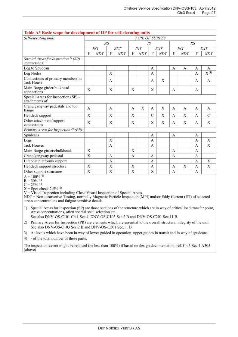
Offshore Service Specification DNV-OSS-103, April 2012Ch.3 Sec.4 – Page 97
Table A3 Basic scope for development of IIP for self-elevating unitsSelf-elevating units TYPE OF SURVEY
AS IS RSINT EXT INT EXT INT EXT
V NDT V NDT V NDT V NDT V NDT V NDTSpecial Areas for Inspection 1) (SP) – connections:Leg to Spudcan A A A A ALeg Nodes X A A X 3)
Connections of primary members in Jack House A A X A A
Main Barge girder/bulkhead connections X X X X A A
Special Areas for Inspection (SP) - attachments of:Crane/gangway pedestals and top flange A A A X A X A A A A
Helideck support X X X C X A X A COther attachment/support connections X X X X X A X A X
Primary Areas for Inspection 2) (PR):Spudcans A A ALegs X A A XJack Houses A A A XMain Barge girders/bulkheads X X A ACrane/gangway pedestal X A A A A ALifeboat platforms support A A A XHelideck support structure X X X A A X A XOther support structures X X X X A AA = 100% 4)
B = 50% 4)
C = 25% 4) X = Spot check 2-5% 4)
V = Visual Inspection including Close Visual Inspection of Special Areas.NDT = Non-destructive Testing, normally Magnetic Particle Inspection (MPI) and/or Eddy Current (ET) of selected stress concentrations and fatigue sensitive details.
1) Special Areas for Inspection (SP) are those sections of the structure which are in way of critical load transfer point, stress concentrations, often special steel selection etc.See also DNV-OS-C101 Ch.1 Sec.4, DNV-OS-C103 Sec.2 B and DNV-OS-C201 Sec.11 B.
2) Primary Areas for Inspection (PR) are elements which are essential to the overall structural integrity of the unit.See also DNV-OS-C103 Sec.2 B and DNV-OS-C201 Sec.11 B.
3) At levels which have been in way of lower guided in operation, upper guides in transit and in way of spudcans.
4) - of the total number of these parts.
The inspection extent might be reduced (be less than 100%) if based on design documentation, ref. Ch.3 Sec.4 A305 (above)
DET NORSKE VERITAS AS

Offshore Service Specification DNV-OSS-103, April 2012Ch.3 Sec.4 – Page 98
B. Annual Survey
B 100 Survey extent
101 The survey will normally cover systems and parts for:
— hull and equipment— machinery and safety systems.— temporary equipment as defined in Ch.1 Sec.1 B200
The survey for the temporary equipment shall only confirm class involvement as specified in Ch.1 Sec.5 B700.
B 200 Hull and equipment for ship-shaped units
201 Survey requirements for hull and hull equipment of ship-shaped units are to be in accordance with TableA4 and Rules for Classification of Ships, Pt.7 Ch.1 Sec.2 B 100 “Hull and Equipment, General - all ships”.
B 300 Structure and equipment for column-stabilised and self-elevating units
301 The survey may be performed on location provided that the structure, including submerged parts, can bethoroughly inspected as specified in the in-service inspection programme. If required, underwater inspectionshall be in accordance with an approved procedure, and using approved personnel and equipment.
302 Units or installations with submerged primary structural members allowing internal access for inspectionmay be omitted from external survey, subject to satisfactory results from the internal survey.
Table A4 Relevant structural survey requirements for ship-shaped offshore unitsShip-shaped units TYPE OF SURVEY
AS IS RSINT EXT INT EXT INT EXT
V NDT V NDT V NDT V NDT V NDT V NDTSpecial Areas for Inspection 1) (SP) – connections:Moonpool openings C A A A A A ATurret A A A A A A ASpecial Areas for Inspection (SP) - attachments of:Crane pedestals and top flange A A A X A X A A A AAnchor windlasses X A X A A A XAnchor chain fairleads C B C A A CHelideck support X X X C X A X A COther attachment/support connections X X X X X A X A XPrimary Areas for Inspection 2) (PR):Crane pedestal X A A A A ALifeboat platforms support A A A XHelideck support structure X X X A A X A XOther support structures X X X X A AA = 100% 3)
B = 50% 3)
C = 25% 3) X = Spot check 2-5% 3)
V = Visual Inspection including Close Visual Inspection of Special Areas.NDT = Non-destructive Testing, normally Magnetic Particle Inspection (MPI) and/or Eddy Current (ECI) of selected stress concentrations and fatigue sensitive details.
1) Special Areas for Inspection (SP) are those sections of the structure which are in way of critical load transfer point, stress concentrations, often special steel selection, etc. See also DNV-OS-C101 Ch.1 Sec.4, DNV-OS-C103 Sec.2 B and DNV-OS-C201 Sec.11 B.
2) Primary Structures (PR) are elements which are essential to the overall structural integrity of the unit.See also DNV-OS-C103 Sec.2 B and DNV-OS-C201 Sec.11 B.
3) - of the total number of these parts.
4) The inspection extent might be reduced (be less than 100%) if based on design documentation, ref. Ch.3 Sec.4 A305 (above)
DET NORSKE VERITAS AS

Offshore Service Specification DNV-OSS-103, April 2012Ch.3 Sec.4 – Page 99
303 Primary structural members which are flooded shall be subject to external survey unless otherwiseagreed. The extent of survey is given in the in-service inspection program, and will comprise visual inspectionof vital parts and may include non-destructive testing of highly stressed areas.304 The means for leakage detection of dry bracings shall be function tested.
305 Internal surfaces in ballast tanks may be subject to survey, including thickness measurements. Thepermissible reduction in thickness is as given for the renewal survey, see also D208.
Condition of protective coating according to A201 to be reported.For areas with general breakdown of the protective coating, close-up examination and thickness measurementsshall be carried out to an extent sufficient to determine both general and local corrosion levels.
306 Accessible and visible parts of the unit's permanent towing arrangement and temporary mooring systemshall be inspected. If the temporary mooring system is part of the mooring system for position keeping onlocation, then accessible and visible parts of the position mooring system shall also be inspected.
307 Items which are important for the reserve buoyancy in connection with stability of the unit shall besurveyed. The survey shall include inspection of external and internal closing appliances, ventilators, air pipes,side scuttles etc., as well as an external inspection of scupper valves and sanitary valves.
308 Remote controls and alarm systems for doors, hatches and watertight dampers shall be surveyed andfunction tested.
309 Guard rails shall be examined.310 For units or installations subjected to annual load line inspections by DNV, the requirements in 307 and309 are considered covered by this inspection.
311 The “Appendix to the classification certificate” and the documents referred to therein, shall be verifiedas kept available onboard the unit.
B 400 Machinery and safety systems for ship-shaped units or installations
401 Survey requirements for machinery and safety systems on ship-shaped units or installations are given inthe Rules for Classification of Ships, Pt.7 Ch.1 Sec.2 C.402 Tank level measurements and helifuel systems shall, however, be surveyed in accordance with offshoreunit requirements, see B503 and B508, respectively.
B 500 Machinery and safety systems for column-stabilised and self-elevating units or installations501 The survey shall include examination of spaces for machinery, boilers and incinerators, and equipmentlocated therein, with particular attention to fire and explosion hazards. As the DNV surveyor deems necessary,running tests and/or opening of machinery, and tests of safety devices and equipment may be required.502 Boilers shall be externally surveyed. The general condition of the boiler including mountings, piping andinsulation shall be ascertained and the surveyor may require opening, removal of insulation etc. if foundnecessary. Safety valves, instrumentation and automation systems shall be tested in operating condition whenfound necessary by the surveyor.
503 The bilge and ballasting system and related subsystems, such as remote valve operation and tank levelindications for column-stabilised units or installations, shall be visually surveyed and tested.504 The brake torques of jacking machinery on self-elevating units shall be checked. Where provided, thefixation rack system shall also be checked.505 For steering gears and/or propulsion thrusters applied for steering purposes, steering functions andalarms shall be tested.
Steering gears for azimuth thrusters, providing the main and/or auxiliary steering function, shall be surveyedas given in Sec.7 Table A1.
506 For units or installations granted a survey arrangement based on an approved planned maintenancesystem (PMS), an annual survey of the PMS is required to prolong the validity of the arrangement. The purposeof this survey is to review and evaluate the previous period's maintenance activities and experience. The annualsurvey shall consist of the following main elements:
a) The maintenance history will be examined in order to verify that the PMS has been operated according tothe intentions and that the system is kept up to date.
b) Evaluation of the maintenance history for main overhaul jobs on the components covered by the continuousmachinery survey (CMS) scheme carried out since last annual survey.
c) Details of corrective actions on components in the CMS scheme shall be made available.
d) If condition monitoring equipment is in use, function tests of this equipment and verification of thecalibration will be carried out as far as practicable and reasonable.
If found necessary by the surveyor, opening or testing of machinery may be required.
DET NORSKE VERITAS AS

Offshore Service Specification DNV-OSS-103, April 2012Ch.3 Sec.4 – Page 100
507 In hazardous areas the following equipment and systems shall be surveyed or tested:
— ventilation systems shall be function tested — the tests shall include emergency stop systems and alarms for lost ventilation— alarms and shutdown functions for pressurised equipment shall be function tested— gas detection equipment shall be function tested— electrical equipment shall be visually inspected.
C. Intermediate Survey
C 100 General101 The survey shall, in general, be carried out as the annual survey, but with extended visual inspection andnon-destructive testing of the structure as given in relevant Rules and in-service inspection programme (whererelevant), see A300.
C 200 Hull and equipment for ship-shaped units201 Survey requirements for hull and hull equipment of ship-shaped units are to be in accordance with TableA4 and Rules for Classification of Ships, Pt.7 Ch.1 Sec.3 B100 “Hull and Equipment, General - all ships”.Ship-shaped offshore units are not subject to EHSR or ESP class notation.
C 300 Structure and equipment for column-stabilised and self-elevating units or installations301 The survey shall, in general, be carried out as the annual survey, but with extended visual inspection andnon-destructive testing of the structure as given in the in-service inspection programme.302 The cathodic protection system shall be surveyed by visual inspection of sacrificial anodes and extent ofcorrosion. Corrosion in welds of vital parts which may be subject to fatigue shall be particularly considered.303 For column-stabilised units or installations, the survey shall, at minimum, cover accessible areas at lightballast draught. 304 For self-elevating units or installations, survey of the full height of the legs is normally required.Potential measurements will also be required if found necessary.305 If the temporary mooring system is part of the mooring system for position keeping on location, then theposition mooring system shall also be inspected. The mooring system shall be function tested during typicalanchor handling operations.
C 400 Machinery and safety systems for ship-shaped units or installations401 Survey requirements for machinery and safety systems on ship-shaped units or installations as are givenin the Rules for Classification of Ships, Pt.7 Ch.1 Sec.3 C.
C 500 Machinery and safety systems for column-stabilised and self-elevating units or installations501 The survey shall generally be carried out as for the annual survey.502 The fire protection arrangement shall be surveyed. For units or installations being inspected by nationalauthorities with respect to fire protection arrangement, the survey for classification may normally beconsidered as covered by this inspection.
D. Renewal Survey, Structure and Equipment
D 100 Hull and equipment of ship-shaped units101 Survey requirements for hull and hull equipment of ship-shaped units are to be in accordance with TableA4 and Rules for Classification of Ships, Pt.7 Ch.1 Sec.4 B100 “Hull and Equipment, General - all ships”.Ship-shaped offshore units are not subject to EHSR or ESP class notation.102 The requirements for close-up examination as per Rules for Classification of Ships, Pt.7 Ch.1 Sec.4Table D.5.1 for single hull oil tankers and Table D6.1 for double hull oil tankers shall be applied in thefollowing cases:
— The ballast tanks have no protective coating or soft coatings.— Tank coatings are in FAIR or POOR condition as defined by A200 of these Rules.— Substantial corrosion is present.
103 The requirements for thickness measurements as per Rules for Classification of Ships, Pt.7 Ch.1 Sec.4Table D.5.2 for single hull oil tankers and Table D6.2 for double hull oil tankers shall be applied in thefollowing cases:
DET NORSKE VERITAS AS

Offshore Service Specification DNV-OSS-103, April 2012Ch.3 Sec.4 – Page 101
— The ballast tanks have no protective coating or soft coatings.— Tank coatings are in FAIR or POOR condition as defined by Sec.4 A200 of these Rules.— Substantial corrosion is present.
104 The following items shall, however, be surveyed in accordance with mobile offshore unit requirements:
— stability (recording for lightweight)— moorings (shall be surveyed according to Sec.6 B, Position Mooring Equipment)— external corrosion— bottom surveys— inspection of sea valves— thruster and tailshaft surveys.
105 Alternative survey arrangements given in D300 may be applied also to ship-shaped units or installations.
D 200 Column-stabilised and self-elevating structures
201 The renewal survey includes the requirements given in B and C. The extent of the survey is given in thein-service inspection programme, and will additionally include the requirements given in 202 to 217.
202 Survey of pipes, valves, couplings, anodes, equipment for level indication, etc. inside tanks and spaces.
203 Tanks shall, as a minimum, be internally surveyed in accordance with Table D1, as far as applicable.
204 Remote level indicating systems for ballast tanks shall be surveyed and function tested.
205 Remote control system for valves in bilge, ballast and cooling water systems shall be surveyed andtested.
206 Remote controls and alarm systems for doors, hatches and watertight dampers shall be surveyed andfunction tested. Spot checks shall be carried out to verify the position indication in the control in situ.
207 Tank bulkheads and tank decks integral with the unit or installation structure shall, as a minimum, behydraulically tested from at least one side to the maximum pressure they can be subjected to in service. Thenumber of tanks to be tested shall be in accordance with Table D1, as far as applicable.
208 Thickness measurements shall be carried out as deemed necessary by the surveyor at the first and secondrenewal surveys after delivery. At the third renewal and subsequent renewals, in addition to the above,mandatory thickness gaugings are to be taken as a minimum in the following areas:
Column Stabilised Units:
— column base tanks which are used for trimming the vessel— main horizontal braces at the connection to column / pontoon or diagonal braces (K-nodes)— selected areas of exposed upper hull where 'box' or 'I' beams receive major concentrated loads— pump room bilge wells.
Table D1 Tank survey and pressure testing 1), 2)
TankAge of unit in years
0-5 5-10 10-15 above 15Sea water 3) all all all allFresh water one one all allFuel, diesel oil one one two halfLubricating oil none none one halfNotes:
1) Tanks of integral type
Guidance note:If a selection of tanks are accepted to be surveyed, then different tanks shall, as far as practicable,be surveyed at each survey, on a rotational basis.Independent tanks within machinery spaces (non-integral, self-supporting tanks which do not formpart of the unit's hull) are normally surveyed as part of the renewal survey for machinery, see E.
---e-n-d---of---G-u-i-d-a-n-c-e---n-o-t-e---
2) If a selection of tanks are accepted to be surveyed, then different tanks shall, as far as practicable, be surveyed at each survey, on a rotational basis.
3) Tanks used as bilge water holding tanks, shall be examined as required for sea water tanks.
DET NORSKE VERITAS AS

Offshore Service Specification DNV-OSS-103, April 2012Ch.3 Sec.4 – Page 102
Self Elevating Units:
— major connections of leg to mat— lattice leg chord at connections to spudcan— spudcan bulkheads at connections to leg chord— leg chords in way of splash zone— load transfer area in way of jack house (external and in way of pre load tanks).
Average corrosion is defined as the average corrosion rate for a typical structural member. Local corrosion is defined as the local corrosion limited by an area of 500 × 500 mm within a plate-field definedby two stiffeners and adjacent web-frames.Average corrosion
— 5% reduction is allowed in “special” areas subject to high fatigue loads. These areas are normally identifiedin the In-Service Inspection Program (IIP)
— 10% reduction is allowed in areas taking part in the global structural strength, or being part of the watertightintegrity of the unit
— 15% reduction is allowed in areas not taking part in the global structural strength and not being part of thewatertight integrity of the unit.
Local corrosion
— 5% reduction is allowed in “special” areas subject to high fatigue loads. These areas are normally identifiedin the In-Service Inspection Program (IIP)
— 15% reduction is allowed for plates in areas taking part in the global structural strength, or being part of thewatertight integrity of the unit
— 20% reduction is allowed in areas not taking part in the global structural strength and not being part of thewatertight integrity of the unit.
Detailed locations for thickness gaugings will be included in the vessels In-service Inspection Programme.209 The jacking systems, including shock pads, shall be examined. A selected number of jacking gear units(about 10%, but not less than one unit per leg) shall be opened up for inspection.210 For self-elevating units or installations, all parts of the legs shall be examined.211 The towing and mooring equipment shall be surveyed as follows:
— all chain lockers and anchor stowage arrangements shall be surveyed— the permanent towing arrangement of the unit shall be surveyed— the temporary mooring systems shall be surveyed— if the temporary mooring systems are part of the mooring system for position keeping on location, the
complete mooring system for position keeping shall be subject to a comprehensive survey. This willinclude thorough visual examination and extensive non-destructive testing of mooring chain or wire rope.This inspection shall include dismantling and non-destructive testing of all joining shackles that have beenin service for more than 5 years
— function testing of the mooring systems shall be performed.
See sub-section L for detailed survey requirements.212 Sea chests and other sea inlets and discharges (above and below the waterline) with valves, includingsanitary valves and scupper valves, shall be opened for survey.Alternative survey methods may be accepted upon special consideration and approved procedures.213 The unit or installation is to undergo a weight or displacement survey and the weight record will bechecked in order to verify the current lightweight and centre of gravity. Where the weight survey indicates adifference from the calculated lightweight in excess of 1% of the operating displacement, an inclining testshould be conducted. For self-elevating units or installations deviations up to 5% of the operating displacementmay be accepted upon special considerations. It is a provision that the weight difference is positioned at themost unfavourable position when calculating the vertical centre of gravity (VCG).The above mentioned requirements may be considered complied with where the national authorities enforcesimilar requirements. In such cases a copy of the report on the weight survey, or on the new inclining test,endorsed by the national authorities, shall be submitted. 214 The presence of required signboards shall be verified.215 The cathodic protection system of the submerged zone shall be surveyed. The efficiency of the systemfor the forthcoming 5-year period shall be confirmed.216 The unit or installation shall be dry docked at the third renewal survey and at each renewal surveythereafter, unless acceptable equivalent alternatives are agreed.See also D300.
DET NORSKE VERITAS AS

Offshore Service Specification DNV-OSS-103, April 2012Ch.3 Sec.4 – Page 103
217 Fixation of major appurtenances to the main structure shall be surveyed. These may typically includecrane pedestals, helicopter decks, lifeboat platforms and heavy deck modules or skids.
D 300 Alternative survey301 Renewal surveys may be carried out on location without interrupting the function of the unit, providedthat they are based on approved procedures outlined in a maintenance system and survey arrangement.See also Ch.2 Sec.3 I for matters that will be taken into consideration for acceptance of surveys on location.302 Provisions regarding fatigue safety factors and corrosion protection shall be in accordance with thefollowing requirements:
— DNV-OS-C102 Appendix A for ship-shaped units— DNV-OS-C103 Appendix A for column-stabilised units— DNV-OS-C104 Appendix A for self-elevating units.
E. Renewal Survey, Machinery and Safety Systems
E 100 General101 Machinery systems and equipment are covered by a survey arrangement if not part of a separate survey.The available machinery survey arrangements are based on the inventory list (see Sec.7 Table A1) establishedfor the unit. The conditions for:
— obtaining and maintaining the survey arrangement, and— the corresponding survey methods to verify that the machinery system is in an acceptable condition is
different for each of the available machinery survey arrangement. If a survey arrangement is not specified,Machinery renewal is set as default.
The following survey arrangements are available:
— machinery renewal, see Sec.7 B— machinery continuous, see Sec.7 C— machinery PMS (Planned Maintenance System), see Sec.7 D— machinery CM (Condition Monitoring), see Sec.7 E— offshore CM (Condition monitoring), see Sec.7 E— PMSRCM (Planned Maintenance System, RCM based), see Sec.7 D.
102 Propulsion systems containing components or elements may change characteristics during the lifetimeand hence influence the torsional behaviour of the system. Such components may be:
— vibration dampers— elastic couplings— speed governor or quick passing through device.
The mentioned components shall be maintained and inspected as approved by DNV or as recommended by themanufacturer. As an alternative to opening up for inspection, measurements may be carried out to confirm the correct dynamicconditions.The torsional vibration measurements shall be carried out and reported to DNV. The results shall be comparedwith the approved limits (torsional vibration calculations).If an elastic coupling is replaced by another type, new torsional vibration calculations shall be submitted forapproval. 103 Auxiliary thrusters shall be examined and tested as follows:
— oil analysis of gear house oil and oil for the CP mechanism— examination of gear and bearings through inspection openings or by other means— examination of external piping systems— examination of bearings, gear and shafts and other relevant parts if any indications of abnormalities are
observed. Satisfactory maintenance according to manufacturer's recommendations to be documented andconsidered as a base for extent of possible opening.Opening to be carried out normally at least every 10 years.Any opening up of a thruster shall be witnessed by a surveyor of the Society.
— function testing of sealing arrangements
DET NORSKE VERITAS AS
Offshore Service Specification DNV-OSS-103, April 2012Ch.3 Sec.4 – Page 104
— function testing of lubrication and hydraulic oil system— function testing of CP mechanism— function testing of thruster unit including alarm system.
Guidance note:It is advised to take oil analysis at regular intervals and always prior to docking in order to ensure that there is no needfor opening of the thruster (e.g. water in the oil).
---e-n-d---of---G-u-i-d-a-n-c-e---n-o-t-e---
104 Temporary equipment is included as long as it is part of the areas and systems covered by class scopeand detailed in the remaining of this chapter. Otherwise the survey shall only confirm class involvement asspecified in Ch.1, Sec.5 B700.
E 200 Electrical installations201 The survey shall comprise examination of the electrical installations with regard to fire and explosionhazards and injury from accidental touching. The survey is also to include testing of correct functioning ofequipment covered by class requirements.202 The insulation resistance of the complete installation shall be measured, and the results presented to thesurveyor. For vessels Survey arrangement PMS and with continuous earth fault monitoring of all distributionsystems and alarm to a continuously manned control station, the following alternative may be accepted:
— Megger test of all generators and main electrical motors— Test of all earth fault monitoring devices— Verification that the vessel has regular maintenance routines for test of earth fault monitoring devices.
203 As far as practicable, the following equipment shall be examined for satisfactory condition:
— main and emergency switchboards— generators— distribution boards— motor starters— electrical motors— converters (e.g. transformers, rectifiers, chargers)— cable installations— enclosures for electrical equipment— lighting equipment— heating equipment— battery installations.
204 The following tests shall be carried out to the extent deemed necessary by the surveyor to ascertain theproper functioning of the equipment:
— generator full load test— generator parallel operation— generator protection relays including non-important load trip, if fitted— generator remote speed control— generator synchronising equipment— power plant interlocking systems— insulation resistance indicating device— emergency generator including switchboards— battery chargers— mechanical ventilation of battery rooms and lockers— navigation lights, with controllers including alarms— electrical motors for essential and important use, e.g. for jacking system at full load— interlocking and/or alarms for pressurised rooms and equipment.
E 300 Instrumentation and automation301 Correct functioning of the various parts of the following systems shall, as far as applicable, be verified:
— alarm and safety system— fire and gas detection system — manual control of machinery— remote control of propulsion machinery— remote control of positioning keeping machinery.
302 It shall be verified that the remote control can be transferred to stand-by manual control in the engineroom in case of power supply failure to the remote control system.303 When cancelling of automatic load reduction and/or automatic stop of engine are provided, thesefunctions shall be demonstrated to the satisfaction of the surveyor.
DET NORSKE VERITAS AS

Offshore Service Specification DNV-OSS-103, April 2012Ch.3 Sec.4 – Page 105
304 Remote shutdown for fuel-oil transfer service pumps and ventilating equipment, together with oil tankoutlet valves where required to be capable of being remotely closed are to be proved satisfactory. Emergencyswitch(s) for all electrical equipment including main and emergency generators, except alarm andcommunication systems and lighting in vital areas such as escape routes and landing platforms, are to be provedsatisfactory (by a combination of testing and review of maintenance records).(IACS UR Z15)
F. Renewal Survey, Tailshaft Survey
F 100 Standard requirements
101 For renewal survey, the tailshaft shall be withdrawn and the following parts examined, where relevant:
— propeller nut and threaded end of tailshaft — cone, key and keyway, including examination of the fore part of the taper and keyway by magnetic particle
inspection method— tailshaft bearing areas— stern tube bushes or bearings. Clearance measurements shall be included— shaftsealing arrangement, including lubricating oil system.
F 200 Alternative survey
201 The following alternative requirements do not apply to tailshafts covered by additional class notationsDYNPOS-AUTS, DYNPOS-AUT, DYNPOS-AUTR and DYNPOS-AUTRO.
202 Subject to 201, an alternative tailshaft survey may be accepted for oil lubricated tailshafts with approvedsealing arrangement, provided that the number of service hours encountered is relatively low, e.g. less than 5000 hours since the last tailshaft survey.
203 At the first renewal survey, the lubricating oil for each of the stern tubes shall be analysed and the resultsforwarded to DNV. Acceptable analysis results, together with satisfactory survey of accessible parts of theshafts including clearance measurements, will normally be considered sufficient.
204 From the fourth renewal survey and onwards, a complete tailshaft survey shall be carried out.
F 300 Tailshaft condition monitoring survey arrangement
301 See Sec.6 Q100 Tailshaft Monitoring.
G. Survey of Geared Thrusters for Main Propulsion and positioning
G 100 Definitions
101 Thrusters for dynamic positioning are thrusters incorporated in systems for dynamic positioning ofoffshore units, where the unit has been granted the additional class notations DYNPOS-AUTS, -AUT, -AUTRor -AUTRO.
102 Thrusters for position mooring are thrusters incorporated in systems for thruster assisted positionmooring of offshore units, where the unit has been granted the additional class notations POSMOOR-TA orPOSMOOR-ATA.
103 Thrusters for propulsion are defined as thrusters which are intended for propulsion or propulsion andsteering of the unit during sea voyage.
G 200 Survey extent
201 Thrusters for main propulsion and positioning shall be subjected to oil samples at regular intervals of notmore that 3 months and analysed by recognized laboratories. The result shall be presented in a way that makesit is easy to read the trends from the previous analyses. Record of results shall be available on board at all times.
A representative oil sample shall be taken before the filters and with the unit in its normal running condition.Oil analysis shall detect iron (Fe) and other solid contamination in addition to possible water content. The watercontent due to condensation is normally not to exceed 0.5%. The oil analysis shall if applicable cover all of thefollowing areas:
— lubrication oil for gears, bearings— sealing boxes— steering gear— propeller.
202 Outboard (wet) parts of the thruster accessible from the outside are covered by the bottom surveys.
DET NORSKE VERITAS AS

Offshore Service Specification DNV-OSS-103, April 2012Ch.3 Sec.4 – Page 106
203 Thrusters for main propulsion and positioning shall be subjected to survey every 5 years. The completesurvey shall include:
1) Evaluation of oil analysis of gear lubrication oil, propeller hydraulic system oil and sealing system oil. See201.
2) Opening up of protection covers.
3) Inspection of power transmission gear (gear clearance to be measured), bearings (axial play to bemeasured), visible parts of shafts and general condition of housing internally.
4) Examination of controllable pitch mechanism oil transmission system and feedback system for wear downand damage.
5) Full stroke ahead and astern to be verified and correct blade position feedback and indication verified.6) Examination of steering column and related sealing and bearing.
7) Running test at MCR.
Provided the scheduled oil sampling has been done (see 201) showing no significant development of particleand / or water contents, the scope described from 2 including 4 can be rescheduled to every alternate completesurvey.
If an approved thrusters Conditioning Monitoring (CM) survey arrangement is in place, opening is requiredonly if any indications of abnormalities are observed.
204 Inboard parts of the thruster accessible from the inside, such as drive motors, shafting system, geartransmissions, pumps and piping systems, alarm, safety and control systems are covered by the main classsurveys of machinery. In addition to geared thrusters this will be applicable for e.g. Voith-Schneider and pumptype thrusters.205 At each overhaul of the thruster unit the following shall be carried out in the presence of a surveyor tothe Society:
— all relevant parts of the components made accessible during overhaul shall be surveyed using adequatemethods, such as visual inspection MPI or DP, wear down measurements
— NDT for sub-surface cracking of the tooth flanks— MPI shall be carried out of gear teeth and at least in way of stress raisers in the shafts— proper assembly of the thruster shall be verified— proper gear mesh shall be documented in same extent as required for new thruster.
At the first complete survey after a successfully overhaul, provided:
— the scheduled oil sampling has been done (see 201) showing no significant development of particle and/orwater contents
— an approved thrusters Conditioning Monitoring (CM) survey arrangement is in place. Ref. Sec.7 E100.
The scope described in 203 from 2 incl.4 can be rescheduled to every alternate complete survey.Mounting of the thruster on board shall be verified and function tested.
If an approved thrusters Conditioning Monitoring (CM) survey arrangement is in place, opening is requiredonly if any indications of abnormalities are observed.
H. Survey of Podded Thrusters for Main Propulsion and positioning
H 100 General
101 The requirements in this sub-section apply to thrusters of podded design, here after denoted pods, forpropulsion and positioning of the unit.
102 Pod survey implies a survey of the pod's internal power transmission elements and driving motorenclosed in the pod, strut and steering column.Pods have two scheduled surveys:
— annual— complete.
For some pod sizes it will be limited access from inside the unit and annual survey should be done to the extentthat is practically possibly. Complete survey might require some dismantling.
103 Parts of the survey may be replaced by an approved condition monitoring arrangement, see ClassificationNote 10.2 Appendix H.
104 At each overhaul, all relevant parts of the components made accessible shall be presented for survey bythe Society, see 203.
DET NORSKE VERITAS AS

Offshore Service Specification DNV-OSS-103, April 2012Ch.3 Sec.4 – Page 107
Assembly and mounting on board shall be verified and tested.
H 200 Scheduled surveys
201 Annual survey
Scope of the annual pod survey by the Society shall include:
— evaluation of lube oil analysis from recognized laboratory— survey of functionality and calibration of onboard control and monitoring system (incl. alarm functions if
fitted for continuous monitoring systems)— review of insulation resistance (megger-test) records— maintenance records for various items, such as alarm tests for bilges, bearing inspections, pod inspections,
maintenance of the slip rings electrical connections, etc— visual inspection of pod motor air cooling system— record of running hours.
202 Complete survey
The complete survey shall include:
— same as for annual— examination of drive motor rotor and stator condition and associated equipment, shafts, and stator fixation
arrangement— internal overall survey, check for cleanliness, oil leaks, general condition— verification of seal tightness— verification of bearing condition (e.g. Boroscopic examination to be carried out)— external survey in dry dock, check housing for cracks, corrosion, damage— verification of seals condition (pod/ship)— verify condition of slewing gears and bearing.
203 At overhaul of the thruster unit the following shall be included in addition to the survey requirementsgiven in 202:
— all relevant parts of the components made accessible during overhaul shall be surveyed using adequatemethods, such as visual inspection and MPI or DP, wear down measurements
— MPI shall be carried out in way of stress raisers in the shafts— proper assembly of the thruster shall be verified.
Mounting of the thruster on board shall be verified and function tested.
I. Boiler Survey
I 100 General
101 Survey of boilers, steam drums, steam generators and/or pipe arrangements shall be carried outaccording to the Rules for Classification of Ships, Pt.7 Ch.1 Sec.5 F.
These requirements are also applicable to steam/thermal oil heated steam generators
J. Thermal Oil Heater Survey
J 100 General
Survey of thermal oil heaters shall be carried out according to the Rules for Classification of Ships, Pt.7 Ch.1Sec.5 G.
K. Survey of the outside of Unit's Bottom and Related Items
K 100 Schedule
101 The outside of the unit's bottom and related items are to be examined two times in any five (5) yearperiod, with an interval not exceeding three (3) years between examinations.
102 Consideration may be given at the discretion of the Society, to any special circumstances justifying anextension of the interval.
DET NORSKE VERITAS AS

Offshore Service Specification DNV-OSS-103, April 2012Ch.3 Sec.4 – Page 108
K 200 Parts to be examined
201 Ship-shaped Units (ship or barge type units)
External surfaces of the hull, keel, stem, stern frame, rudder, nozzles, and sea strainers are to be selectivelycleaned to the satisfaction of the attending surveyor and examined together with appendages, the propeller,exposed parts of stern bearing assembly, rudder pintle and gudgeon securing arrangements, sea chest andstrainers, and their fastenings (as applicable).
Propeller shaft bearing, rudder bearing, and steering nozzle clearances (as applicable) are to be ascertained andreported upon.
202 Self-elevating Units
External surfaces of spudcans, mat, underwater areas of legs, together with their connections as applicable, areto be selectively cleaned to the satisfaction of the attending surveyor and examined.
At each dry-docking survey or equivalent, after renewal survey No. 2, the surveyor is to be satisfied with thecondition of the internal structure of the mat or spudcans. Leg connections to mat and spudcans are to beexamined at each dry-dock survey or equivalent.
203 Column-stabilised Units
External surfaces of underwater areas of columns, bracing and their connections, sea chests, and propulsionunits as applicable, shall be examined.
K 300 Survey planning and record keeping
301 Plans and procedures for underwater inspection shall be submitted for review in advance of the surveyand made available on board. Submitted data, after review by the Society, will be subject to revision if foundto be necessary in light of experience.
Guidance note:The Society may consider alternative methods for providing adequate assurance that a unit's bottom is in a satisfactorycondition at the mid-term class period survey.A survey based on such alternative methods is subject to acceptance by the relevant flag administration.
---e-n-d---of---G-u-i-d-a-n-c-e---n-o-t-e---
L. Survey of Towing, Temporary and Position Mooring Equipment
L 100 Types of survey
101 Annual survey is a visual examination to ascertain the general condition of the relevant items. The surveyis normally carried out on location with the unit at operational draft and the mooring system in use. No specialinspection aids are required and no disruption to the unit’s operation is intended.
102 Intermediate survey is normally carried out on location. No special aids are required. Ref Sec.6 B400.
103 Renewal survey will require appropriate cleaning with good access and adequate lighting, i.e. the specialinspection aids and facilities usually associated with a sheltered water visit.
Alternatively, the owner may opt for a continuous survey by providing an extra mooring line which is regularlyinspected in special facilities onshore and exchanged with lines installed on the unit. This arrangement isnormally noted by an MO which gives the last/next survey date of each mooring line.
L 200 Annual survey
201 Towing, Temporary Equipment are to be subject to visual inspection.
L 300 Intermediate survey
301 Towing, Temporary Equipment are to be subject to visual inspection.
L 400 Renewal survey
401 The towing and mooring equipment shall be surveyed as follows:
— all chain lockers and anchor stowage arrangements shall be surveyed — the permanent towing arrangement of the unit shall be surveyed — the temporary mooring systems shall be surveyed — function testing of the mooring systems shall be performed.
L 500 Anchor chains; acceptance criteria and repair
501 Diameter loss due to abrasion and corrosion
Links or joining shackles with minimum cross-sectional area less than 81% of the original nominal area is to
DET NORSKE VERITAS AS

Offshore Service Specification DNV-OSS-103, April 2012Ch.3 Sec.4 – Page 109
be rejected. The equivalent reduction in diameter is 10%. Two perpendicular measurements are to be taken andthe average compared to the allowable 10% reduction.
502 Missing studs
Missing studs on stud link chain is not acceptable. Links are to be removed or studs are to be refitted using anapproved procedure.
503 Corroded studs
As guidance, if the measured stud cross-sectional area is less than 40% of the nominal link (bar) cross-sectionalarea, links should be removed or studs should be refitted using an approved procedure.
504 Studs secured by fillet welds
Grade 3 chains are sometimes fitted with studs secured by fillet welds. In service the welds may crack. Thefollowing applies:
1) any axial or lateral movement is unacceptable. Links are be removed or studs are to be re-welded using anapproved procedure
2) links with intact fillet welds but with gaps exceeding 3 mm between the stud and the link should be removedor repaired using an approved procedure. This because the stud welds will eventually crack due tovibrations when chain is running over fairlead at speed during anchor handling
3) existing links which are found to have the stud fillet welded at both ends are subject to specialconsideration.
505 Studs secured by press fitting and mechanical locking
With this design of stud there is little prospect of the stud falling out even if it is loose. However, loose studshave caused fatigue at the edge of imprints. The following applies:
1) axial stud movement up to 1 mm is acceptable
2) axial stud movement greater than 2 mm is unacceptable. Links are to be removed or studs are to be pressedusing an approved procedure
3) acceptance of axial stud movement from 1 to 2 mm must be evaluated based on the environmental conditionsof the unit’s location and expected period of time before the chain is again available for inspection
4) lateral movement up to 4 mm is acceptable provided there is no realistic prospect of the stud falling out5) welding of studs is not acceptable.
506 Cracks, gouges, and other surface defects
Defects may be removed by grinding to a depth of 7% of original nominal diameter provided the resultingcross-sectional area is at least 81% (90% for Position Mooring Equipment) of the original nominal area.The resulting grooves are to have a length along the link of approximately six times the depth and a bottomradius of approximately three times the depth. Grooves are to be blended into the surrounding surface to avoidany sharp contours. Complete elimination of defects is to be verified by MT or PT.
507 Gross-distortion
Links showing distortion/ miss-shape are to be rejected.
508 Joining shackle defects and repair
Experience has shown a number of anchors and chains lost due to joining shackle failure. Joining shackle is tobe rejected if cracks and other defects are found on the machined surfaces. In addition, all joining shackles onthat chain which are of the same design and which have an equal or greater service life are also to be consideredcarefully with a view to rejection. Cracks and other defects on the remaining surface may be removed bygrinding.509 Distortion
Shackles showing distortion/ miss-shape are to be rejected.
510 Tapered pins
Tapered pins holding the parts of joining shackles together must make good contact at both ends and the recessof counterbore at the large end of the pin holder should be solidly plugged with a peened lead slug to preventthe pin from working out.511 Replacement of links and joining shackles
Links or shackles beyond repair are to be replaced with joining shackles in compliance with current Rules andguided by the following good marine practice:
1) joining shackles should pass through fairleads and windlasses in the horizontal plane
DET NORSKE VERITAS AS

Offshore Service Specification DNV-OSS-103, April 2012Ch.3 Sec.4 – Page 110
2) since joining shackles have much lower fatigue lives than ordinary chain links as few as possible should beused
3) if a large number of links meet the discard criteria and these links are distributed in the whole length, thechain should be replaced with new chain.
Any other type of replacement links are subject to special approval.
DET NORSKE VERITAS AS

Offshore Service Specification DNV-OSS-103, April 2012Ch.3 Sec.5 – Page 111
SECTION 5PERIODICAL SURVEY EXTENT FOR ADDITIONAL SERVICE
NOTATIONS
A. General
A 100 Introduction
101 This section presents the standard extent of surveys for retention of additional service notationsapplicable to offshore LNG/LPG production and storage units. The requirements shall be applied in additionto those for main class notation presented in Sec.4.
B. LNG or LPG Production and/or LNG or LPG Storage Units and Installations
B 100 Application
101 The requirements in B apply to units or installations with class notations:
LNG or LPG Production Unit or LNG or LPG Production Installation
LNG or LPG Storage Unit or LNG or LPG Storage Installation.
B 200 Survey arrangement
201 Annual and complete periodical surveys may be carried out on location based on an approved plannedmaintenance system without interrupting the function of the unit or installation.
B 300 Annual survey
301 Structures, supporting equipment and heavy modules applied in the production operation shall besurveyed.
302 The following items shall be subjected to a general examination:
— storage tank (LNG/LPG/Condensate) openings and pressure/vacuum valves— produced fluid (LNG/LPG/Condensate) piping systems— pump and compressor rooms— escape routes— fire extinction systems in storage tank and pump/compressor room area— fire extinguishing system associated with transfer systems
303 The following components and systems shall be surveyed and tested for correct functioning as foundnecessary by the surveyor:
— gas detection systems for flammable and toxic gases— fire detection system— storage tank level measurements— general alarm system and communication between control stations.
304 In hazardous areas the following equipment and systems shall be surveyed and tested:
— ventilation system including overpressure alarms— alarms and shutdown for pressurised equipment and rooms— electrical equipment and cables— self-closing gastight doors, air locks, openings and accesses— protection devices for combustion equipment and engines.
305 The emergency shutdown system for:
— wellhead valves and production facilities— all non-essential electrical equipment— all essential electrical equipment
shall be surveyed and function tested. Special attention shall be given to both manual and automatic activation,power supply and alarms.
Where cross connections between piping system for production and safe piping system exist, the means foravoiding possible contamination of the safe system with the hazardous medium shall be surveyed.
DET NORSKE VERITAS AS

Offshore Service Specification DNV-OSS-103, April 2012Ch.3 Sec.5 – Page 112
B 400 Cargo Handling and Containment System – Annual Survey
401 Annual survey extent for LNG/LPG related handling and storage systems, outside the processing plant,should generally follow the requirements given in Rules for Classification of Ships Pt. 7 Ch. 1 Sec. 2 B500 andC 200.
B 500 Complete periodical survey
501 The requirements given in 300 apply with the addition given in 400.
502 For objects having boilers burning crude oil or slop, survey and testing of control equipment includingmonitoring systems and shutdown functions related to the following systems shall be carried out:
— ventilation and gas-tightness, fuel supply line and boiler with boiler front lagging— fuel pumps and heating arrangement— drain pipe ducts and automatic closing drain traps— inert and purging systems— manual and automatic quick closing valves and shutdown systems— boiler hood ventilation system— boiler compartment ventilation— boiler front extinguishing system— pilot burner arrangement— gastight bulkhead penetrations— gas detection system— fuel heater.
503 For objects having turbines, engines or boilers burning gas, survey and testing of the safety and controlequipment and alarm and shutdown functions related to the following systems shall be carried out:
— gas heating arrangement— ventilation arrangement— protection and flame screens— gas freeing and purging systems— manual and automatic shutdown system— gas detection system— pilot flame burner or “fuel floor” arrangement— governor stability switching from gas fuel to oil, or vice versa.
504 Function test of instrumentation and safety devices for equipment and systems in 303 shall be carried out.
505 The fire extinguishing system in or at:
— storage tank (LNG/LPG/Condensate) area— pump/compressor room— engine and boiler room— helicopter deck— transfer system areas
shall be surveyed and tested for correct functioning.
506 It shall be verified that required signboards are in order.
507 The drainage system of hazardous area shall be surveyed.
508 The insulation resistance of the electrical installation in the hazardous area shall be checked.
509 The fireman's outfit shall be surveyed.
510 Industrial equipment included in class according to Ch.2 Sec.3 shall be surveyed. Attention is to be paidto fire and other hazards. Thickness checking of pipework shall be carried out and records reviewed by thesurveyor, as applicable. Hydrostatic testing may be requested by the surveyor.
B 600 Cargo Handling and Containment System – Complete Periodical Survey
601 Complete periodical survey extent for LNG/LPG related handling and storage systems, outside theprocessing plant, should generally follow the requirements given in Rules for Classification of Ships Pt.7 Ch.1Sec.4 B500. Offshore units however have the option of conducting surveys in-situ rather than in drydock.
DET NORSKE VERITAS AS

Offshore Service Specification DNV-OSS-103, April 2012Ch.3 Sec.5 – Page 113
C. LNG/LPG Loading Units and Installations
C 100 Application101 The requirements in B apply to units or installations with class notations:LNG/LPG Loading Unit or LNG/LPG Loading Installation.
C 200 Survey arrangement201 Annual and complete periodical surveys may be carried out on location based on an approved operationmanual.
DET NORSKE VERITAS AS
Offshore Service Specification DNV-OSS-103, April 2012Ch.3 Sec.6 – Page 114
SECTION 6PERIODICAL SURVEY EXTENT FOR ADDITIONAL CLASS;
SPECIAL EQUIPMENT AND SYSTEM NOTATIONS
A. General
A 100 Introduction
101 This section presents the standard extent of surveys for retention of additional system and special facilityclass notations applicable to production and storage units or installations. The requirements for main andservice class notations are presented in Sec.2 and Sec.3.
B. Position Mooring Equipment
B 100 Application
101 The requirements in B apply to units or installations with class notations:
— POSMOOR— POSMOOR-V— POSMOOR-TA— POSMOOR-ATA.
102 If the unit is in DP mode and not in POSMOOR mode at time of survey and hence equipment's/functionality related to the POSMOOR notation is not available for survey/testing a reduced survey scope maybe accepted. Annual, intermediate or complete survey depending on time since last survey is to be carried outbefore the mode is taking into use.
B 200 Types of surveys
201 Annual surveys may be carried out with the unit at operational draft and the mooring system in use. Nospecial inspection aids are required and no disruption to the unit's operation is intended.
202 Intermediate survey may be carried out on location. No special aids are required.
203 Renewal survey will require appropriate cleaning with good access and adequate lighting.
The complete mooring system for position keeping on location is subject to comprehensive survey, includingopening up and NDT of selected parts of windlasses and winches and fairleads.
Critical parts of all mooring chains or wires and accessories will be thoroughly visually examined and subjectedto extensive NDT when required. The extent and type of survey is dependent on the design such as corrosionprotection / allowance and fatigue, see B500, B600 and B700.
For units with permanently locked off chain arrangement, particular attention will be paid to the hanging offarrangement.
204 Mooring lines:
Alternatively, the owner may opt for a continuous survey by providing an extra mooring line, which is regularlyinspected in special facilities onshore and exchanged with lines installed on the unit. This arrangement isnormally noted by an MO which gives the last/next survey date of each mooring line. At each renewal surveyfor the hull, the attending surveyor shall carry out the equivalent of the intermediate survey on each mooringline and renewal survey extent on the other parts of the mooring system, i.e. windlass, fairleads, anchors, etc.which are not covered by the continuous survey cycle.
205 Owners are to ensure that the mooring system can be adequately surveyed. An inspection and survey planshall be submitted to the Society for approval at the commencement of the in-service phase.
The following information shall be submitted to the Society:
— sample chain/wire/fibre rope certificate— sample joining shackle certificate (one of each type of shackle used)— design fatigue life— fatigue life used since new / last inspection— latest inspection reports— history of chain/wire/fibre rope, e.g. inspections, chain/ wire /fibre rope breaks, joining shackles— planned remaining field life— future inspection plans.
DET NORSKE VERITAS AS

Offshore Service Specification DNV-OSS-103, April 2012Ch.3 Sec.6 – Page 115
B 300 Annual survey
301 Accessible and visible parts of the unit's or installation’s mooring system for position keeping on locationshall be inspected.302 The unit or installation log shall be reviewed in order to verify that the unit or installation has beenoperating within the environmental conditions specified for POSMOOR in the “Appendix to the classificationcertificate”. The anchor chain records are also to be reviewed.303 Thruster operation shall be function tested for units or installations with notation POSMOOR-TA orPOSMOOR-ATA.
B 400 Intermediate survey
401 The requirements given in 300 apply.
402 Windlass and fairlead pockets:
Visual inspection of windlass and fairlead pockets. Particular attention to be paid to:
— rate of wear on pockets, including relative rate of wear between links and pockets — mismatch between links and pockets, including improper support of the links in the pockets.
403 Mooring system function testing for units with winches installed:
Function testing of the mooring system. Particular attention to be paid to:
— the function of brakes — the smooth passage of links or wire and joining shackles over the windlass or winch and fairlead — the absence of chain jumping or other irregularities.
404 Units and installations with notation POSMOOR-ATA shall be surveyed as given in C, as far as isapplicable.
B 500 Complete periodical survey of fairleads and winches irrespective of fatigue life factors of the mooring system
501 The requirements given in 400 apply.
502 The fairleads shall be inspected visually and by ROV as far as possible. All fairleads are to be inspectedwith special attention to wear and tear of fairlead wheels and malfunctioning.
503 Visual inspection of windlass and fairlead pockets shall be carried out. Particular attention shall be paidto:
1) Rate of wear on pockets, including relative rate of wear between links and pockets.
2) Mismatch between links and pockets, including improper support of the links in the pockets.
504 Special attention shall be given to the holding ability of the windlass. The chain stopper and the resultantload path to the unit's structure should be inspected and its soundness verified.
505 Special attention shall be given to the holding ability of the winch and the satisfactory operation of thepawls, ratchets and braking equipment. The soundness of the resultant load path to the unit's structure shall beverified.
506 Proper spooling of the wire on the winch drum shall be verified and drums and spooling gear adjustmentsmade if required.
B 600 Complete periodical survey - systems designed before 1996 (no fatigue analysis and corrosion allowance)
601 For mooring systems designed without corrosion protection/allowance and not designed with respect tofatigue the following shall be carried out in addition to B500:
— inspection of the unit’s log and anchor line records— thruster operation is to be function tested. (Units with TA or ATA notation)— dismantling and non-destructive testing of all joining shackles which have been in service for more than 5
years, except for LTM shackles— function testing of windlasses/winches and fairleads, including testing of brake torque— units with notation TA and ATA are also to be inspected according to Sec.6 C Dynamic Positioning System— complete inspection of mooring system including:
— visual examination and extensive non-destructive testing of critical parts of all anchor chains, wire andfibre ropes and accessories
— dimension control of chain and connection elements— inspection of cathodic protection system of sockets.
DET NORSKE VERITAS AS

Offshore Service Specification DNV-OSS-103, April 2012Ch.3 Sec.6 – Page 116
602 The survey of steel wire ropes consists of a 100% visual control, and the following items shall becovered:
— the nature and number of wire breaks— wire breaks at the termination— localised grouping of wire breaks— fracture of strands— reduction of rope diameter including breaking of core— external wear and corrosion— deformation— termination area.
603 It is advised that checkpoints are made for every 100 m. If areas of special interest are detected, thedistance should be significantly reduced. 604 For acceptance/rejection criteria the following standards shall be used as guideline:
— for wire rope: ISO Standard 4309-2004, API RP 2I— for fibre rope: DNV-RP-E304— for chain: Sec.4 K500 and API RP 2I with the following addition: the anchor chains shall be replaced if the
diameter of the chain with the breaking strength used in the design is reduced by 2%.
B 700 Complete periodical survey – fatigue design life factor 3701 A survey scheme as outlined herein will only apply for mooring systems with recommended connectionelements. The scheme applies to all production and/or storage units designed according to:
— DNV MOU Rules Pt.6 Ch.2 Position Mooring (POSMOOR), dated January 1996 (Design life factor 3)— API RP2SK Third Edition, October 2005 (Design life factor 3)— DNV-OS-E301 Position Mooring, dated June 2001 (Design life factor 3).
702 Recommended connection elements in long term mooring systems shall be purpose made elements suchas triplates and D-shackles of Long Term Mooring (LTM) type.703 Assumptions and conditions for acceptance of approach:
— the remaining fatigue life exceeds the expected field life by a factor of 3— loss of one line will not lead to a critical situation for the installation— if any defects are found on the chain/wire during visual inspection, all chains/wires are to be pulled for
visual inspections— chain/wire inspection is carried out under supervision by DNV surveyors results of ROV inspection to be
verified by DNV surveyors— all studs found loose are to be pressed tight— the most heavily loaded (extreme tension) line is to be inspected. If a different line is most heavily utilised
in fatigue, then this line is also to be inspected— no twist shall exist between upper & lower fairlead. Any twists shall be removed — fairlead and winches surveyed according to B500— units with notation TA and ATA are also to be inspected according to Sec.4 C Dynamic Positioning System.
704 All mooring lines shall be inspected offshore by use of ROV within 5 years. At least 2 out of every 8 chain lines (25%) shall be included in visual /MPI inspection at a suitable offshore oronshore facility as follows:
— 100% visual— 100% MPI of joining links— 10% of the links are to have overall MPI (may be reduced for benign waters)— diameter measurements of the chain link every 100th link. The anchor chains shall be replaced if the
diameter of the chain with the breaking strength used in the design is reduced by 2%— 2-neck measurement values to be noted every 100th link (measurement of the two diameters taken at the
neck of the link at the mating surface).
705 All the remaining chain/wires shall be ROV inspected with respect to the following:
— overall visual inspection (including cleaning if necessary)— go/no go gauge on 2 link wear every 100th link— wear and scouring in touch down area— anchors and anchor jewellery— chain/wire attachments to the hull shall be surveyed visually as far as possible, if not accessible by ROV— wear and tear in chain links where the mooring line is locked of in the chain stopper— chain links in the fairlead pockets and close to fairleads shall be given special attention— six strand wire ropes shall be inspected according to B602.
DET NORSKE VERITAS AS

Offshore Service Specification DNV-OSS-103, April 2012Ch.3 Sec.6 – Page 117
706 If the ROV inspection reveals defects that are considered as critical, i.e. cracks, severe pitting and wearand tear, a more detailed inspection including MPI will be required.707 Normally connection elements such as Kenter shackles, pear links, C-links and D-shackle with lockingpin through bow and bolt, and swivels are not accepted in long term mooring systems. However, if suchequipment is accepted installed they shall either be dismantled and subjected to non-destructive testing of allmachined surfaces, or be replaced with new elements at least every 5 years.
B 800 Complete periodical survey – fatigue life factor 5-8 or greater
801 The requirements in B800 are valid for mooring system design according to:
— DNV MOU Rules Pt.6 Ch.2 Position Mooring (POSMOOR) dated January 1996 (design life factor 10)— API RP2SK Third Edition, October 2005 (design life factor 10)— DNV-OS-E301 Position Mooring, dated June 2001 (design life factors 5 - 8).
802 For assumptions and conditions for acceptance of approach, see B704.
803 All mooring lines shall be inspected offshore by use of ROV during a 5 years period as follows:
— 100% overall visual inspection (including cleaning if necessary)— diameter measurements of the chain link every 100th link of at least 1 out of 8 chains lines (12.5%).
The anchor chains shall be replaced when the diameter of the chain with the breaking strength used in thedesign is reduced by 2%. If unexpected wear and tear or corrosion reveals, the diameter measurements shallbe extended. The plan for the extended inspection shall be approved by the surveyor.
— 2-neck measurement values to be noted every 100th link (measurement of the two diameters taken at theneck of the link at the mating surface)
— go/no go gauge on 2 link wear every 100th link— wear and scouring in touch down area— anchors and anchor jewellery if available— chain/wire /fibre rope attachments to the hull shall be surveyed visually as far as possible.
804 Special attention shall by paid to connection elements such as:
— LTM shackles and their bolts and locking devices— wear and tear of connection elements— corrosion with attention to severe pitting— steel wire rope sockets and their cathodic protection system— chain stoppers— wear and tear of chain links in chain stoppers and fairleads— damage to the protection (sheathing) of steel wire rope.
805 If the ROV inspection reveals defects that are considered as critical, i.e. cracks, severe pitting and wearand tear, a more detailed inspection including MPI will be required.
806 Normally connection elements such as kenter shackles, pear links, C-links and D-shackle with lockingpin through bow and bolt, and swivels are not accepted in long term mooring systems. However, if suchequipment is accepted installed they shall either be dismantled and subjected to non-destructive testing of allmachined surfaces, or be replaced with new elements at least every 5 years.
C. Dynamic Positioning System
C 100 General101 These Rules do not include verification of requirements or recommendations in regard to the vesselsoperation or other characteristics.102 The requirements in this sub-section apply to units with class notation:
DYNPOS-AUTS or DYNPOS-AUT or DYNPOS-AUTR or DYNPOS-AUTRO and to units with previouscorresponding class notations.
103 For units with qualifier (A) given as:
DYNPOS-AUTR(A) or DYNPOS-AUTRO(A) notation, also the annual survey shall be carried out in accordance with the requirement for complete survey,as given in C300 as applicable.
104 For class notations with the qualifier (A) an updated FMEA report with a corresponding FMEA testprogram shall be kept onboard, and shall be used as basis for the testing.
105 If the unit is in POSMOOR mode and not in DYNPOS mode at time of survey and hence equipment's/functionality related the DYNPOS notation is not available for survey/testing a reduced survey scope may be
DET NORSKE VERITAS AS
Offshore Service Specification DNV-OSS-103, April 2012Ch.3 Sec.6 – Page 118
accepted. Annual, intermediate or complete survey depending on time since last survey is to be carried outbefore the mode is taking into use.
C 200 Annual survey
201 System maintenance documentation, including information regarding hardware and software changes,shall be reviewed.
Guidance note:This requirement includes, in addition to the DP control system, the joystick control system and other systemsnecessary for performing position keeping, e.g. thruster control system.
---e-n-d---of---G-u-i-d-a-n-c-e---n-o-t-e---
202 The electrical installation in excess of the main class requirements shall be visually inspected, i.e.installations comprising the dynamic positioning system, e.g. controllers and operating stations for DP andindependent joystick, references systems, sensors and mode change system.
203 The technical condition of the DP system shall be verified during the survey.Guidance note:Verification of the technical condition of the DP system denotes testing to verify that the DP system is capable ofpositioning the unit, and thus validating that system functionality is in place.
---e-n-d---of---G-u-i-d-a-n-c-e---n-o-t-e---
Guidance note:Testing should preferably be done during a sea trial. However, in the case where this is inconvenient (e.g. the unit isin the middle of a long term operation) the survey may be performed during regular operations. This may imply thatit may not be possible to test all different operational modes.
---e-n-d---of---G-u-i-d-a-n-c-e---n-o-t-e---
204 If the survey is carried out when the unit is undergoing
regular operations, then tests that possibly can introduce unacceptable risks shall not be performed.
205 Capacity of UPSs and other battery systems serving the DP control system, including its peripherals,shall be verified.
The alarm for loss of charging power shall be verified.Guidance note:If the survey is carried out during regular operations, then the capacity of the batteries need not be proven by testing.
---e-n-d---of---G-u-i-d-a-n-c-e---n-o-t-e---
206 For class notation DYNPOS-AUTRO, normal working condition of the back-up DP control systemshall be verified.
Guidance note:If the survey is carried out during regular operations, then control need not be transferred to the back-up DP controlsystem.
---e-n-d---of---G-u-i-d-a-n-c-e---n-o-t-e---
207 Emergency stop of thrusters from the DP control centre shall be tested. If the survey is carried out whenthe unit is undergoing regular operations, then testing shall not be performed if there is any possibility ofintroducing unacceptable risks.
C 300 Complete survey (5 years)
301 With the unit in DP mode, a sea trial shall be performed.
302 The complete system shall be tested in all operational modes. The testing shall include simulation ofdifferent failure conditions to verify switching of modes, back-up systems and the alarm system.
303 The different modes of thruster control from the DP control centre(s) shall be tested:
— manual control— joystick control (independent joystick, if installed)— DP control— transfer of control.
Manual override i.e. by thruster lever control and independent joystick control shall be demonstrated duringnormal operation and during failure conditions.
304 Emergency stop of DP thrusters from DP control centre to be tested.
DET NORSKE VERITAS AS

Offshore Service Specification DNV-OSS-103, April 2012Ch.3 Sec.6 – Page 119
305 All sensors, peripheral equipment and reference systems shall be tested:
— verify correct operation and adequate accuracy— failure of sensors and reference systems shall be simulated to check the alarm system and the switching
logic— switch-over between reference systems as input to controller shall be carried out to assure that warnings,
alarms and information to operator are satisfactory
Guidance note 1:Due to practicalities some reference systems may be unavailable during the tests. In such cases the testing can beperformed by the crew as soon as possible after survey. When testing is left to the crew this must be recorded in thesurvey report, and a condition of class or memo to owner must be issued. The condition of class or memo to ownercan be deleted based on a signed test report from the master.
---e-n-d---of---G-u-i-d-a-n-c-e---n-o-t-e---
Guidance note 2:The survey of the thruster unit shall be carried out as for thrusters for propulsion and dynamic positioning. Surveysof the thrusters are separate survey elements and these surveys do not need to take place at the same time as the DPsurvey.
---e-n-d---of---G-u-i-d-a-n-c-e---n-o-t-e---
306 Alarm for loss of position and heading out of limit shall be demonstrated.
307 The electrical installation in excess of the main class requirements, shall be visually inspected, i.e.installations comprising the dynamic positioning system, e.g. controllers and operating stations for DP andindependent joystick, references systems, sensors and mode change system.
308 Single failures in thruster control systems including signal wire breaks of thruster command andfeedback signals shall be tested in order to verify safe response on the thrust output. Equivalent testing mayalso be required for rudders controlled by the DP control system.
309 Overload prevention shall be tested.
Guidance note:If it is possible to induce overload by setting out thrust command from the DP control system (e.g. by use of joystickfunction) then the overload protection function (e.g. pitch reduction) shall be tested.
System configuration and/or available power considerations may lead to this test being omitted.
---e-n-d---of---G-u-i-d-a-n-c-e---n-o-t-e---
310 Capacity of UPSs and other battery systems serving the DP control system including it peripherals shallbe verified by testing. Alarm for loss of charging power shall also be verified.
311 For class notations DYNPOS-AUTR and DYNPOS-AUTRO the required redundancy with respect todefined single failures modes shall be verified by redundancy testing.
312 For class notations DYNPOS-AUTR and DYNPOS-AUTRO the FMEA report and FMEA testprogram shall be verified to ensure that they have been updated when alterations have been done.
Guidance note:This requirement is only valid for units with class request after 1 July 2004.
---e-n-d---of---G-u-i-d-a-n-c-e---n-o-t-e---
313 For class notations DYNPOS-AUTR and DYNPOS-AUTRO correct functioning of the ConsequenceAnalysis facility shall be verified as far as possible.
314 For class notation DYNPOS-AUTRO testing shall also be performed on the back-up DP control system.Switchover to back-up shall be tested, and monitoring of back-up control system status on the main controlsystem shall be verified.
D. Single Point Mooring
D 100 Application
101 The requirement in D applies to units with class notation:
SPM.
D 200 Annual survey
201 The annual survey shall be carried out in concurrently with the annual survey for main class.
DET NORSKE VERITAS AS

Offshore Service Specification DNV-OSS-103, April 2012Ch.3 Sec.6 – Page 120
E. Loading Computers for Damage Control
E 100 Application
101 The requirement in E applies to units with class notation:
LCS-DC.
E 200 Annual survey
201 The survey required in the following shall be carried out concurrently with the annual survey for mainclass.
202 It shall be checked that the approved in-service test programme for all sensors has been followed.
F. Production Plant
F 100 Application
101 The requirements in F apply to units or installations with class notation:
PROD (LNG) or PROD(LPG).
F 200 Survey arrangement
201 Annual and complete periodical survey may take account of an approved planned maintenance system.As far as possible disruption of the function of the unit or installation should be minimised.
F 300 Annual survey
301 An overall survey of production related equipment, structures and systems with particular attention tostructural integrity, fire or explosion hazards, safety systems and personnel protection shall be carried out. Ifdeemed necessary by the surveyor running test, NDT, and/or opening up of equipment may be required.
302 For equipment installed subsea at time of annual survey a review of the maintenance manual or test logis an acceptable survey method provided a satisfactory recording system and acceptable maintenanceprocedure exist.
303 Riser system and production or well control components shall be visually surveyed as far as accessible.If deemed necessary by the surveyor pressure testing shall be carried out.
304 Pressure vessels and heat exchangers shall be externally surveyed. Safety valves, instrumentation andsystems on tanks or separators shall be surveyed and tested in operating condition as found necessary by thesurveyor.
305 High pressure or capacity pumps and compressors shall be externally surveyed and function tested asdeemed necessary by the surveyor.
306 Piping systems including flexible pipes shall be surveyed as deemed necessary by the surveyor.
307 Pressure relief and depressurising valves shall be surveyed and tested as deemed necessary by thesurveyor.
308 Riser handling devices, lifting devices for production and related operations, wire ropes, endattachments, and sheaves shall be surveyed. Function testing of safety devices shall be carried out as foundnecessary by the surveyor.
309 Survey of accessible parts of the following structures shall be carried out to confirm structural integrityand condition of securing arrangement:
— flare or vent— pancakes— skids.
310 The process and utility safety systems shall be surveyed during operation and tested for correctfunctioning as found necessary by the surveyor with particular emphasis on:
— shutdown valves— shutdown instrumentation— shutdown sequence and logic— interconnection with emergency shutdown system— regulation or control system— alarm system.
A review of the maintenance manual or test log is an acceptable survey method provided a satisfactoryrecording system and an acceptable maintenance procedure exist.
DET NORSKE VERITAS AS

Offshore Service Specification DNV-OSS-103, April 2012Ch.3 Sec.6 – Page 121
311 Drainage system for produced liquids for hazardous areas shall be surveyed.
312 Water protection system in process area shall be surveyed and function tested as deemed necessary bythe surveyor.
313 Drainage and containment system for cryogenic fluids and spray protection measures shall be surveyed.
F 400 Complete periodical survey
401 The requirements given in 300 apply with the additions given in 402 to 410.
402 Riser joints, flexible pipes and other riser system components to be closely visually surveyed formechanical damage and corrosion. Surface NDT methods shall be used to investigate critical areas for cracks.Thickness measurements and dimensioned checks may be required if found necessary by the surveyor.Satisfactory functioning and pressure integrity shall be confirmed.
403 The production or well control equipment shall be subject to internal inspection to the extent necessaryto reveal current condition. Satisfactory functioning and pressure integrity shall be confirmed.
404 Pressure vessels and heat exchangers shall be subjected to internal surveys. If this is not practical thenuse of thickness measurements may be considered. Examination of related equipment such as valves, pipingand fittings shall be carried out. Pressure testing to rated working pressure shall be carried out.
405 Correct setting of valves shall be confirmed.
406 High pressure or capacity pumps and compressors shall be surveyed by opening up fully or partly asdeemed necessary by the surveyor. Pressure testing to be carried out when relevant and found necessary by thesurveyor.
407 Overhead lifting equipment and lifting devices shall be dismantled to the extent necessary to evaluatecurrent condition. Main loading parts shall be checked by NDT. Thickness measurements as deemed necessaryto be carried out. Wire ropes shall be surveyed.
408 Structural condition of the venting/flaring arrangement shall be surveyed. NDT of main structuralcomponents may be required as deemed necessary by the surveyor.
409 The fixed fire protection systems in process area and hydrocarbon loading/unloading area shall besurveyed and tested for correct functioning.
410 Function test of safety devices and instrumentation listed in 310 shall be carried out.
G. Helicopter Deck
G 100 Application
101 The requirements in G apply to units or installations with class notation (Ref. DNV-OS-E401):
HELDK
G 200 Complete periodical survey
201 All surveys of the helicopter deck arrangement shall be concurrent with the complete periodical surveyof the hull.
202 An overall survey shall be carried out with particular emphasis on the structural integrity of the deck withsupporting structure, and is normally to include examination of the following components and arrangements:
— drainage arrangements— surface protection on wooden decks— safety net— lashing arrangements for the helicopter— arrangements for the prevention of sliding— helicopter deck including support— fire safety installation (for qualifiers S, SH)— communication equipment (for qualifiers S, SH)— obstacles and marking (for qualifiers SH).
H. Crane
H 100 Application
101 The requirements in H apply to units or installations with class notation:
CRANE.
DET NORSKE VERITAS AS

Offshore Service Specification DNV-OSS-103, April 2012Ch.3 Sec.6 – Page 122
H 200 Annual survey
201 The following survey requirements shall be carried out concurrently with the annual survey for mainclass.
202 An overall survey shall be carried out with particular emphasis on structural integrity, includingexamination of:
— wire ropes and end attachments— blocks and sheaves— hooks with accessories— shackles— bearings of boom heel and eyebolt connections— securing arrangement for crane during passages— support structure.
203 The slewing system (slewing bearing or hook rollers) including tightness of bolts shall be examined asrequired by the surveyor.
204 Examination and functional testing of the following shall be performed as found necessary by thesurveyor:
— correct adjustment of brakes— resistance measurement of electrical systems— leakages in hydraulic system— safety devices— emergency stop function— fire extinguisher.
205 The load charts, marking and components certificates shall be verified as available and in order.
H 300 Complete periodical survey
301 Structural parts shall undergo thickness measurements as deemed necessary by the surveyor.
302 The following components shall be dismantled (opened up) and/or checked by MPI (magnetic particleinspection):
— boom heel bearings— fixed sheaves— blocks— axle pin and housing— eyebolt connections— hooks, ring and balls.
The slewing ring shall be opened up, and internal fillets, raceway and bolts shall be subjected to MPI.
Alternatively:
— slewing bearings may be subject to relevant accepted NDT in order to check for defects in fillets andraceways
— crane with approved securing device (retainer) fitted, opening up is not required— at least 50% of the holding down bolts shall be drawn and subjected to MPI.
303 Flatness and condition of bearing mounting flanges shall be checked.
304 Load testing shall be performed as outlined in Form No. CG 2 in the DNV Standard for Certification No.2.22 Lifting Appliances.
I. Additional Fire Protection
I 100 Application
101 The requirements in I apply to units or installations with class notations:
F-A, F-M, F-C
F-AM, F-AC, F-MC, F-AMC
I 200 Complete periodical survey, all F-class notations
201 Fire pumps including emergency fire pump and prime movers shall be surveyed and tested.
202 Fireman's outfit and compressors for charging the air bottles, shall be surveyed.
DET NORSKE VERITAS AS

Offshore Service Specification DNV-OSS-103, April 2012Ch.3 Sec.6 – Page 123
I 300 Complete periodical survey, F-A301 The requirements in 200 apply, with the following additions:
— fire retarding partitions in the accommodation shall be surveyed— hose stations, together with their equipment, in the accommodation, shall be surveyed— automatic fire-detecting and alarm systems including release arrangement for self-closing doors in
passageways, stairways and machinery casings shall be surveyed and tested.
I 400 Complete periodical survey, F-M401 The requirements in 200 apply with the following additions:
— main and local extinguishing systems in engine and boiler rooms including detection and alarmarrangements shall be surveyed and tested. The quantity of extinguishing medium shall be checked
— portable dry powder fire extinguishers, and spare charges shall be checked— hose stations in the engine and boiler rooms together with their equipment shall be surveyed.
I 500 Complete periodical survey, F-C501 The requirements in 200 apply with the following additions:
— smoke detector systems for cargo holds, cargo pump rooms, compressor rooms and other service roomsshall be surveyed and tested
— CO2-systems shall be surveyed and the CO2-quantity verified. Thickness measurements and or pressuretesting of CO2-bottles may be required if found necessary by the surveyor
— foam systems shall be surveyed and the foam quantity verified. Foam forming concentrate shall be analysedevery five years
— dry chemical powder systems shall be surveyed and the powder quantity verified— fire extinguishing systems for deck area shall be tested— portable fire extinguishers for the deck area and cargo holds shall be surveyed. Spare charges shall be checked— hose stations on deck together with their equipment shall be surveyed.
I 600 Complete periodical survey, F-AM601 The requirements in 300 to 400 apply.
I 700 Complete periodical survey, F-AC701 The requirements in 300 and 500 apply.
I 800 Complete periodical survey, F-MC801 The requirements in 400 and 500 apply.
I 900 Complete periodical survey, F-AMC901 The requirements in 300 to 500 apply.
J. Winterization, Cold climate and Ice
J 100 Winterization101 ApplicationThese requirements apply to units with the following class notations: WINTERIZED or WINTERIZED ARTIC.102 Annual surveyAnti-icing and de-icing switchboards shall be surveyed. It shall be verified that the heating load on each circuitis according to relevant marking on the switchboards.103 The equipment for de-icing and anti-icing shall be examined, including the following items:
— heaters — covers — equipment for manual de-icing — radar equipment — heating coils — steam tracing lines.
104 Thermal protection suits including face masks, gloves and boots in sufficient number for all crewmembers to be verified on board.105 The ice search light on wheelhouse top shall be tested.
DET NORSKE VERITAS AS

Offshore Service Specification DNV-OSS-103, April 2012Ch.3 Sec.6 – Page 124
106 For units with class notation WINTERIZED ARCTIC (design temp.) the annual survey requirementsfor class notation CLEAN shall be carried out, see N200.
J 200 Deicing and anti-icing systems201 ApplicationThese requirements apply to units with the following class notations: DEICE or DEICE-C.202 Annual surveyVisual inspection of anti-icing and de-icing switchboards and confirm heating load on each circuit accordingto marking on the switchboards.203 Examination of equipment for de-icing and anti-icing including:
— heaters — covers — equipment for manual de-icing — radar equipment — heating coils — steam tracing lines.
K. Periodically Unattended Machinery Space and Machinery Centralised Operated
K 100 Application101 The requirements in K apply to units or installations with class notations:E0ECO.
K 200 Annual survey201 The surveyor shall verify that systematic maintenance and functional testing of instrumentation has beenperformed and documented. The general condition of the following shall be to the satisfaction of the surveyor:
— installation of instrumentation equipment with regard to electrical and mechanical condition, labels,signboards etc.
— control panels— local indicating instruments.
202 Correct functioning of the following systems shall be verified:
— alarm systems— safety systems— remote control systems— automatic control systems— emergency lighting systems in engine room— communication systems— fire alarm and fire protection systems.
K 300 Complete periodical survey301 The requirements given in 200 apply, subject to the additions given in 302 to 305.302 Correct functioning of the various parts of the following systems shall be verified to the satisfaction ofthe surveyor:
— each alarm system— each safety system— each fire detector— automatic control loops— manual control of machinery.
303 The following manoeuvres shall be undertaken for survey of remote control of propulsion machinery:
— from stop to ahead— from ahead to astern— stop— from stop to astern
DET NORSKE VERITAS AS

Offshore Service Specification DNV-OSS-103, April 2012Ch.3 Sec.6 – Page 125
— stop by operating the emergency device.
304 The surveyor shall verify effective transfer from remote control to stand-by manual control in the engineroom in case of power supply failure to the remote control system.
305 Where provided, cancelling of automatic load reduction and/or automatic stop of engine functions shallbe demonstrated to the satisfaction of the surveyor.
L. Hull Monitoring System
L 100 Application
101 The requirements in L apply to units or installations with class notation:
HMON (...).
L 200 General
201 The purpose of the survey is to ensure the maintenance of the hull monitoring system as specified for theclass notation.
202 The operation manual shall be available to the attending surveyor during periodical surveys. In additionto the manual the following documents shall be available:
— arrangement and layout— test program for software— in-service test program— maintenance procedures.
L 300 Annual survey
301 The operation of the hull monitoring system shall be verified by a DNV surveyor:
— to ensure that the value of the stress as defined is compatible with the output of the loading instrument forthe current condition
— by examination of the recorded data for compliance with the requirements.
302 The monitoring system shall be calibrated annually. The calibration shall be verified by a DNV surveyor.
303 It shall be verified that the following items are available and in order:
— calibration certificates and recommendations for all relevant components of the monitoring system— operations manual.
M. Fatigue Methodology for Ship-Shaped Units
M 100 Application
101 The requirements in M apply to ship-shaped units with class notation:
FMS.
M 200 General
201 The purpose for the survey is to ensure that the fatigue critical details have no indications of fatiguedamage.
202 The fatigue critical areas given in the drawings of fatigue critical areas or in accordance with theinspection program shall be surveyed.
M 300 Annual survey
301 The extent of inspections for annual survey shall be in accordance with the in service inspection program.
M 400 Intermediate survey
401 The extent of inspections for intermediate survey shall be in accordance with the in service inspectionprogram.
M 500 Complete periodical survey
501 The extent of inspections for complete survey shall be in accordance with the in service inspectionprogram
DET NORSKE VERITAS AS

Offshore Service Specification DNV-OSS-103, April 2012Ch.3 Sec.6 – Page 126
N. Environmental notations
N 100 Additional oil pollution prevention measures - fuel oil systems
101 No specific survey requirements. Complete periodical survey is considered covered by renewal surveyof main class.
N 200 CLEAN or CLEAN DESIGN
201 Application
The requirements apply to units with class notations:
CLEAN or CLEAN DESIGN.
202 Annual surveys
The basic requirement is that the unit holds a valid international pollution prevention certificate.
For the oil pollution prevention certificate, the following shall be checked onboard during survey:
— certificates for type approved oily water separating or filtering equipment, process unit and oil contentmeters
— oil record book entries — approved SOPEP manual — means of control of sludge — standard discharge connection.
Additionally, the following shall be examined and tested, as applicable:
— oil filtering equipment (15 ppm) and process unit with alarm — automatic stopping device (15 ppm) — separation of oil fuel and water ballast system — sludge tank and discharge arrangement externally.
203 In addition the following shall be checked or verified as applicable:
— all refrigerant consumption figures — consumption figures for fire fighting substances with global warming potential (GWP) > 0 — garbage record book — oil record books and cargo record book — fuel oil log — NOx emission control equipment log, where applicable — ballast water management log — documentation of antifouling used during dry-dockings since last review.
N 300 Vapour Control Systems (VCS)
301 Application
The requirements in O apply to units or installations with class notations:
VCS-1, VCS-1B
VCS-2, VCS-2B
VCS-3.
302 Complete periodical survey
Requirements for survey of the additional class notations VCS-1 and VCS-2 are considered covered by theRules for units or installations with class notations Storage Unit or Storage Installation.
For VCS-1B and VCS-2B the following instruments and equipment shall be surveyed and tested:
— the means to inert the vapour transfer hose— oxygen analyser with alarms— detonation arrester.
Requirements for survey of the remaining parts of the installation are considered covered by the Rules for unitsor installations with class notations Storage Unit or Storage Installation.
For VCS-3 the details of periodical survey requirements will be specified in the unit’s or installation’s“Appendix to the classification certificate”.
DET NORSKE VERITAS AS

Offshore Service Specification DNV-OSS-103, April 2012Ch.3 Sec.6 – Page 127
O. Safety and Environmental Protection Management System
O 100 Application101 The requirements in O apply to units or installations with class notation: SBM.
O 200 Survey requirements201 Surveys shall be in compliance with the Rules for Classification of Ships, Pt.7 Ch.3.
P. Noise, Vibration and Comfort Rating
P 100 General101 ApplicationThe requirements in P apply to units with the class notations: VIBR and/or COMF.102 GeneralIf major modifications to the vessel, which may influence the vibration conditions onboard, are carried out, newmeasurements may have to be taken in order to maintain the notation. This will be decided by the Society.Otherwise requirements for survey of these additional class notations are considered covered by the renewalsurvey main class.
Q. Special Feature Notations
Q 100 Tailshaft Monitoring101 The requirements in Q apply to units with class notation: Tailshaft Monitoring (TMON).102 GeneralFor oil lubricated tailshafts that are monitored to ascertain the condition of the tailshaft system duringoperation, and that fulfils the design requirements in Ch.2 Sec.6 S500 the Society will not require any specifictime interval between complete tailshaft surveys.In such cases a tailshaft condition monitoring survey arrangement (class notation TMON) will be granted.The class notation is applicable to conventional, podded and thruster propulsion systems. Other arrangementswill be subject to special consideration.Units with more than 3 years since the last tailshaft withdrawal are normally to carry out a complete tailshaftsurvey in connection with the initial TMON implementation survey.
Guidance note:The requirement for a complete survey at TMON implementation may be waived provided the following:
a) Complete records are presented to the Society containing relevant measurements concerning TMON for a periodcovering the last 3 years, showing satisfactory results.
b) Such records shall at least include monthly measurements of stern tube bearing temperatures with correspondingsea water temperatures, oil consumption, water content in oil, and in case of roller bearing, recordings of vibrationor shock pulse measurements or trend analysis.
c) Where fluid film bearings are applied, bearing clearances from last dry docking and wear down measurementstaken since last shaft withdrawal shall be presented.
---e-n-d---of---G-u-i-d-a-n-c-e---n-o-t-e---
103 Annual surveyThe following conditions for TMON operation must be verified during annual survey:
a) On board oil analysis for checking of water content in the stern tube oil shall be performed monthly andrecorded in the TMON record file by the chief engineer/maintenance supervisor.
b) At least two oil samples per year shall be submitted to a recognized laboratory for analysis testing of watercontent, iron, chromium, copper, tin, silicon, natrium and magnesium.
c) The documentation of the laboratory analysis shall be kept on board, and shall contain a conclusionregarding the condition of the oil and its suitability for further use.
d) The report from the oil analysis presented to the surveyor at annual surveys shall be less than three months old.
DET NORSKE VERITAS AS

Offshore Service Specification DNV-OSS-103, April 2012Ch.3 Sec.6 – Page 128
104 Dismantling of propellersDismantling of keyed propellers will be required at intervals of maximum 5 years, and keyless propellers every15 years. The following parts shall be surveyed as applicable:
— propeller nut— tailshaft threaded end— key and cone including examination of the keyway and the fore part of the taper by an approved crack
detection method.
DET NORSKE VERITAS AS

Offshore Service Specification DNV-OSS-103, April 2012Ch.3 Sec.7 – Page 129
SECTION 7MACHINERY ALTERNATIVE SURVEY ARRANGEMENTS
A. General
A 100 General101 Machinery systems and equipment listed in Table A1 shall be surveyed according to one of the fivemachinery survey arrangements if not part of a separate survey.
Table A1 Machinery surveys
Item
Machinery Renewal and Machinery
Continuous
Machinery PMS Machinery CM PMS/RCM
Survey method 1) Main propulsion and DYNPOS
Prime movers
Diesel engine 1 3 3 and 4 5Steam turbines 2) 1 1 4*16) 5Gas turbines See F See F See F See F Electrical main motors, including frequency converters
2 3 3 or 4* 5
Shafting
Thrust-and intermediate shaft including bearings, clutch, couplings and torsional and axial vibration damper
2 3 3 and 4 5
Tailshaft Separate survey Sec.4 F
Separate surveySec.4 F
Separate survey Sec.4 F
Separate survey Sec.4 F
Gears 3)
Shafts, pinions, gear wheels, couplings and bearings, clutch
1 3 3 and 4* 5
Power Take Off /In (PTO/PTI) 1 3 4* 5
Power consumption
Propeller Separate survey Sec.4 G Separate
survey Sec.4 G
Separate survey Sec.4 G
Separate survey Sec.4
G
Thruster, Pods Separate survey Sec.4 G Separate
survey Sec.4 G
Separate survey Sec.4 G
Separate survey Sec.4
G Steering
Power actuating system
Actuator 2 3 3 or 4 5Hydraulic pumps 2 3 3 or 4 5Electric motors 2 3 3 or 4 5Pipes, valves and filters 2 3 3 5
Auxiliary machinery
Prime movers
Diesel engine 1 3 3 and 4 5Turbines 2) 1 3 4* 5Electrical motors, including frequency converters 2 3 3 or 4* 5
Hydraulic motors 2 3 3 5
Thruster Shafts, pinions, gear wheels, couplings and bearings 12) 13) 14) 15)
Separate survey Sec.4 G
Separate survey
Sec.4 G
Separate survey
Sec.4 G
Separate survey
Sec.4 FG Generators 2 3 3 or 4* 5
Shafting Shaft, couplings, clutch and torsional and axial vibration damper
2 3 3 5
DET NORSKE VERITAS AS

Offshore Service Specification DNV-OSS-103, April 2012Ch.3 Sec.7 – Page 130
Gears 3)
Shafts, pinions, gear wheels, couplings and bearings
2 3 4* 5
Power Take Off (PTO) 2 3 4* 5
Sea water cooling system
Pumps, Electrical motor and starter 12 3 4 5
Heat exchangers 1 3 3 or 4 5Pipes, valves and filters 5) 10) 2 3 3 5
Fresh water cooling system
Pumps, electrical motor and starter 2 3 4 5
Heat exchangers 1 3 3 or 4 5Pipes, valves and filters 10) 2 3 3 5
Lubricating oil system
Pumps, electrical motor and starter 2 3 4 5
Heat exchangers 1 3 3 or 4 5Pipes, valves and filters 4) 9) 10) 2 3 3 5
Fuel oil system
Pumps, electrical motor and starter 2 3 4 5
Heat exchangers 1 3 3 or 4 5Pipes, valves and filters 9) 13) 2 3 3 5
Bilge and ballast system
Pumps, Electrical motor and starter 1 or 2 3 4 5
Ejectors/ Educturs 1 3 3 5Pipes, valves and filters inside machinery space 5) 8) 10)
2 3 3 5
Steam system
Boiler, main and auxiliary Separate survey Sec.4 H Separate
survey Sec.4 H
Separate survey Sec.4 H
Separate survey Sec.4
H
Thermal oil Separate survey Sec.4 I Separate survey Sec.4 I
Separate survey Sec.4 I
Separate survey Sec.4
I Heat exchangers 1 3 3 or 4 5Pipes, valves and filters inside machinery space 6) 10)
2 3 3 5
Feed water and condensate system
Pumps, electrical motors and starters 2 3 4 5
Turbines 2) 1 1 4* 5Evaporators and condensers with ejectors 1 3 3 5
Heat exchangers 1 3 3 or 4 5Pipes, valves and filters 10) 2 3 3 5
Compressed air system
Air compressors, piston 2 3 3 or 4* 5Air compressors, screw 2 3 3 or 4 5Emergency compressors 2 3 3 or 4 5Compressed air receivers 7) 1 3 3 5Pipes, valves and filters inside machinery space 10) 2 3 3 5
Table A1 Machinery surveys (Continued)
Item
Machinery Renewal and Machinery
Continuous
Machinery PMS Machinery CM PMS/RCM
Survey method 1)
DET NORSKE VERITAS AS

Offshore Service Specification DNV-OSS-103, April 2012Ch.3 Sec.7 – Page 131
Hydraulic system
Pumps, electrical motor and starter 2 3 4 5
Pipes, valves and filters inside machinery space 10) 2 3 3 5
Controllable pitch propeller oil distribution box 2 3 3 5
Controllable pitch propeller inboard actuators 2 3 3 5
Hydraulic motors 2 3 3 or 4 5Cargo handling systems
Piston pumps Centrifugal pumps Screw pumps
222
333
4*44
555
Electrical motors and starters 2 3 3 and 4 5
Turbines 2) 1 1 4* 5Heat exchangers 1 3 3 or 4 5Pipes, valves and filters 10) 2 3 3 5Gas compressors 1 3 3 or 4* 5Diesel engine 1 3 3 and 4 5
Control, alarms, safety systems and indications
Control systems
Propulsion 2 3 3 5Steering 2 3 3 5Auxiliary machinery 2 3 3 5Cargo handling systems 2 3 3 5
Alarms
Propulsion 2 3 3 5Steering 2 3 3 5Auxiliary machinery 2 3 3 5Cargo handling systems 2 3 3 5
Safety systems
Propulsion 2 3 3 5Steering 2 3 3 5Auxiliary machinery 2 3 3 5Cargo handling systems 2 3 3 5
Indicating systems
Propulsion 2 3 3 5Steering 2 3 3 5Auxiliary machinery 2 3 3 5Cargo handling systems 2 3 3 5
Electrical installations Switchboards 2 3 3 5Distribution board 2 3 3 5Electrical equipment 2 3 3 5Cable installations 2 3 3 5Navigation light controllers 2 3 3 5Mechanical ventilation of battery lockers or rooms 2 3 3 5
Table A1 Machinery surveys (Continued)
Item
Machinery Renewal and Machinery
Continuous
Machinery PMS Machinery CM PMS/RCM
Survey method 1)
DET NORSKE VERITAS AS
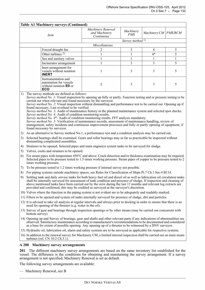
Offshore Service Specification DNV-OSS-103, April 2012Ch.3 Sec.7 – Page 132
A 200 Machinery survey arrangements
201 The different machinery survey arrangements are based on the same inventory list established for thevessel. The difference is the conditions for obtaining and maintaining the survey arrangement. If a surveyarrangement is not specified, Machinery Renewal is set as default.
The following survey arrangements are available:
— Machinery Renewal, see B
Miscellaneous Forced draught fan 2 3 4 5Other turbines 2) 1 1 4* 5Sea and sanitary valves 1 1 1 1Incinerator arrangement 1 3 3 5Inert arrangement for vessels without notation INERT
1 3 3 5
Instrumentation and automation for vessels without notation E0 or ECO
2 3 3 5
1) The survey methods are defined as follows:Survey method No. 1: Visual inspection by opening up fully or partly. Function testing and or pressure testing to be carried out when relevant and found necessary by the surveyor.Survey method No. 2: Visual inspection without dismantling and performance test to be carried out. Opening up if found necessary. Last overhaul to be verified.Survey method No. 3: Audit of maintenance history in the planned maintenance system and selected spot checks.Survey method No. 4: Audit of condition monitoring results.Survey method No. 4*: Audit of condition monitoring results. FFT analysis mandatory. Survey method No. 5: Verification of maintenance records, assessment of maintenance handling, review of management, safety incidents and continuous improvement processes and fully or partly opening of equipment, if found necessary by surveyor.
2) As an alternative to Survey method No.1, a performance test and a condition analysis may be carried out.
3) Selected bearings shall be examined. Gears and roller bearings may as far as practicable be inspected without dismantling complicated assemblies.
4) Strainers to be opened. Selected pipes and main engine(s) system tanks to be surveyed for sludge.
5) Valves, cocks and strainers to be opened.
6) For steam pipes with temperature 450°C and above: Crack detection and/or thickness examination may be required. Selected pipes to be pressure tested to 1.5 times working pressure. Steam pipes of copper to be pressure tested to 2 times working pressure.
7) To be pressure tested to 1.2 times working pressure if internal survey not possible.
8) For piping systems outside machinery spaces, see Rules for Classification of Ships Pt.7 Ch.1 Sec.4 B114.
9) Settling tank and daily service tanks for both heavy fuel oil and diesel oil as well as lubrication oil circulation tanks shall be internally surveyed for assessment of tank condition and presence of sludge. If inspection and cleaning of above mentioned tanks have been carried out by the crew during the last 12 months and relevant log extracts are provided and confirmed, this may be credited as surveyed at the surveyor's discretion.
10) Valves where the function in the piping system is not evident are to be adequately and readably marked.
11) Filters to be opened and system oil tanks internally surveyed for presence of sludge, dirt and particles.
12) It is advised to take oil analysis at regular intervals and always prior to docking in order to ensure that there is no need for opening of the thruster (e.g. water in the oil).
13) Survey of gear and bearings through inspection openings or by other means (may be carried out concurrent with bottom survey).
14) Opening up and Survey of bearings, gear and shafts and other relevant parts if any indications of abnormalities are observed. Satisfactory maintenance according to manufacturer's recommendations to be documented and considered as a base for extent of possible opening. Any opening up of a thruster to be witnessed by a DNV surveyor.
15) Hydraulic oil, lubrication oil, alarm and safety systems are to be surveyed as applicable for respective systems.
16) In addition to the renewal survey for Machinery CM, a limited internal inspection shall be carried out on main steam turbines (ref. CN 10.2 Ch.3.1).
Table A1 Machinery surveys (Continued)
Item
Machinery Renewal and Machinery
Continuous
Machinery PMS Machinery CM PMS/RCM
Survey method 1)
DET NORSKE VERITAS AS
Offshore Service Specification DNV-OSS-103, April 2012Ch.3 Sec.7 – Page 133
— Machinery Continuous, see C— Machinery PMS (Planned Maintenance System), see D— Machinery CM (Condition Monitoring), see E— PMS RCM, see G.
B. Machinery Renewal
B 100 General101 Machinery renewal is the default survey arrangement for machinery.102 Machinery systems and equipment with corresponding survey method for this arrangement see TableA1.
B 200 Annual survey201 Annual survey of the machinery and safety systems shall be carried out according to Sec.4 B400 andB500.
B 300 Renewal survey301 The survey shall include the machinery systems and equipment given in the vessels Inventory List atleast to the extent specified in Table A1.
B 400 Structure and equipment for column-stabilised and self-elevating units401 The survey may be performed on location provided that the structure, including submerged parts, can bethoroughly inspected as specified in the in-service inspection programme. If required, underwater inspectionshall be in accordance with an approved procedure, and using approved personnel and equipment.402 Units or installations with submerged primary structural members allowing internal access for inspectionmay be omitted from external survey, subject to satisfactory results from the internal survey.403 Primary structural members which are flooded shall be subject to external survey unless otherwiseagreed. The extent of survey is given in the in-service inspection program, and will comprise visual inspectionof vital parts and may include non-destructive testing of highly stressed areas.404 The means for leakage detection of dry bracings shall be function tested.405 Internal surfaces in ballast tanks may be subject to survey, including thickness measurements. Thepermissible reduction in thickness is as given for the renewal survey, see also Sec.4 D207.Condition of protective coating according to Sec.4 A201 to be reported.For areas with general breakdown of the protective coating, close-up examination and thickness measurementsshall be carried out to an extent sufficient to determine both general and local corrosion levels. 406 Accessible and visible parts of the unit's permanent towing arrangement and temporary and emergencymooring system shall be inspected. If the temporary mooring system is part of the mooring system for positionkeeping on location, then accessible and visible parts of the position mooring system shall also be inspected.407 Items which are important for the reserve buoyancy in connection with stability of the unit shall besurveyed. The survey shall include inspection of external and internal closing appliances, ventilators, air pipes,side scuttles etc., as well as an external inspection of scupper valves and sanitary valves.408 Remote controls and alarm systems for doors, hatches and watertight dampers shall be surveyed andfunction tested.409 Guard rails shall be examined.410 For units or installations subjected to annual load line inspections by DNV, the requirements in 407 and409 are considered covered by this inspection.411 The “Appendix to the classification certificate” and the documents referred to therein, shall be verifiedas kept available onboard the unit.
B 500 Machinery and safety systems for ship-shaped units or installations501 Survey requirements for machinery and safety systems on ship-shaped units or installations are given inthe Rules for Classification of Ships, Pt.7 Ch.1 Sec.2 C.502 Tank level measurements and helifuel systems shall, however, be surveyed in accordance with offshoreunit requirements, see B503 and B508, respectively.
B 600 Machinery and safety systems for column-stabilised and self-elevating units or installations601 The survey shall include examination of spaces for machinery, boilers and incinerators, and equipmentlocated therein, with particular attention to fire and explosion hazards. As the DNV surveyor deems necessary,running tests and/or opening of machinery, and tests of safety devices and equipment may be required.
DET NORSKE VERITAS AS

Offshore Service Specification DNV-OSS-103, April 2012Ch.3 Sec.7 – Page 134
602 Boilers shall be externally surveyed. The general condition of the boiler including mountings, piping andinsulation shall be ascertained and the surveyor may require opening, removal of insulation etc. if foundnecessary. Safety valves, instrumentation and automation systems shall be tested in operating condition whenfound necessary by the surveyor.603 The bilge and ballasting system and related subsystems, such as remote valve operation and tank levelindications for column-stabilised units or installations, shall be visually surveyed and tested.604 The brake torques of jacking machinery on self-elevating units shall be checked. Where provided, thefixation rack system shall also be checked.605 For steering gears and/or propulsion thrusters applied for steering purposes, steering functions andalarms shall be tested.Steering gears for azimuth thrusters, providing the main and/or auxiliary steering function, shall be surveyedas given in Table A1.606 For units or installations granted a survey arrangement based on an approved planned maintenancesystem (PMS), an annual survey of the PMS is required to prolong the validity of the arrangement. The purposeof this survey is to review and evaluate the previous period's maintenance activities and experience. The annualsurvey shall consist of the following main elements:
a) The maintenance history will be examined in order to verify that the PMS has been operated according tothe intentions and that the system is kept up to date.
b) Evaluation of the maintenance history for main overhaul jobs on the components covered by the continuousmachinery survey (CMS) scheme carried out since last annual survey.
c) Details of corrective actions on components in the CMS scheme shall be made available.d) If condition monitoring equipment is in use, function tests of this equipment and verification of the
calibration will be carried out as far as practicable and reasonable.
If found necessary by the surveyor, opening or testing of machinery may be required.607 In hazardous areas the following equipment and systems shall be surveyed or tested:
— ventilation systems shall be function tested — the tests shall include emergency stop systems and alarms for lost ventilation— alarms and shutdown functions for pressurised equipment shall be function tested— gas detection equipment shall be function tested— electrical equipment shall be visually inspected.
C. Machinery Continuous
C 100 General101 Machinery continuous is a survey arrangement based on surveys during the class period. 102 Machinery systems and equipment with corresponding survey method for this arrangement see TableA1.103 Machinery continuous is operated under the following conditions:
1) The machinery systems are to be surveyed according to Table A1.2) General requirements for intervals for continuous surveys are given in the Rules for Classification of Ships
Pt.7 Ch.1 Sec.8 C.
104 Machinery continuous allows that some machinery systems and equipment are credited based ondocumented maintenance history presented by the chief engineer under the following conditions:
1) The following information shall be available:
— name of the chief engineer— licence number, date of issue and validity— name of the Administration that issued the licence.
The manager shall confirm, through a statement signed by a designated person in the company, the chiefengineers that can carry out surveys based on sub-items 2 to 5. This statement shall be found onboard.Guidance note:A template for such a statement is available from DNV. For the definition of a designated person, see Rules forClassification of Ships Pt.7 Ch.5 Sec.2 A500.
---e-n-d---of---G-u-i-d-a-n-c-e---n-o-t-e---
DET NORSKE VERITAS AS

Offshore Service Specification DNV-OSS-103, April 2012Ch.3 Sec.7 – Page 135
2) Half of all items covered by the vessels inventory list, of which there is more than one, can be surveyed bythe chief engineer.
3) Documented maintenance history shall include extract of engine logbook, maintenance history, wearmeasurements forms, etc.
4) The surveyor can, if found necessary, require a re-survey of items surveyed by the chief engineer.5) All surveys taking place at ports where the Society is represented shall be carried out by surveyors of the
Society.
C 200 Annual survey201 Annual survey of the machinery and safety systems are carried out according to Sec.4 B400 and B500.
C 300 Renewal survey301 Renewal survey is not a part of this survey arrangement.
D. Machinery PMS (Planned Maintenance System)
D 100 General101 a) Machinery PMS is a survey arrangement based on audits of an approved and implemented plannedmaintenance system onboard which shall cover all component surveys in the machinery list for the vessel.
a) The audits shall be part of the main class annual survey.b) The Owner/Manager is responsible for ensuring that the Chief Engineer/Maintenance Supervisor is
qualified to register and carry out maintenance on all class related machinery items.Guidance note:In reference to Res. 741 (18) ISM Code, 1995 STCW A-III as amended.
---e-n-d---of---G-u-i-d-a-n-c-e---n-o-t-e---
c) The Chief Engineer/Maintenance Supervisor shall be the responsible person on board in charge of theMachinery PMS.
d) If the conditions for the survey arrangement are not complied with, or in case of change of technicalmanagement of the vessel, the Survey Arrangement Machinery PMS will be cancelled and substituted bySurvey Arrangement Machinery Continuous or Survey Arrangement Machinery Renewal, as applicable.
102 The Survey Arrangement Machinery PMS shall be operated under the following conditions:
a) The surveyor may credit relevant component surveys in the machinery list based on the recordedmaintenance, except for the following, that shall be surveyed by the Society:
— Main steam piping — feed water piping — Steam turbines for propulsion and power generation — reduction gears in steam driven propulsion plants.
b) Change or a major upgrade of planned maintenance system shall always be notified to the Society and willbe subject to new approval. Guidance note:Major upgrade meaning changes that affects reporting of maintenance on machinery items, or changes that mightimplicate additional training of crew.
---e-n-d---of---G-u-i-d-a-n-c-e---n-o-t-e---
c) Back up of the PMS database, making it possible to restore all data, shall be taken at least once a week. d) The surveyor can, if found necessary, require a re-survey of items reported by the Chief Engineer/
Maintenance Supervisor.e) All damage/break-downs on class related machinery items shall be reported to class and included in the
system.
103 The planned maintenance system onboard shall comply with the following requirements:
a) The system shall be computer based. b) The system shall be able to produce a maintenance history report of all main overhauls carried out for a
specific time period.
DET NORSKE VERITAS AS

Offshore Service Specification DNV-OSS-103, April 2012Ch.3 Sec.7 – Page 136
c) Corrective maintenance shall be possible to be especially identified in the system and traceable. d) The system shall include at least the applicable machinery and equipment listed in Table A1. All these
components shall be identified with their belonging the Society's machinery item code or alternatively thefull name of the component survey according to the machinery list for the specific unit.
e) All main overhaul jobs on class related components shall be identified as class related jobs in themaintenance system.
f) For units with class notation E0 or ECO, the system shall include the periodical testing of control, alarmand safety components and systems required by Ship Rules Pt.6 Ch.3 Sec.1. These jobs shall be especiallyidentified in the system and include test routines and set-points based on Ship Rules Pt.6 Ch.3 Sec.3 TableA1 to Table A10.
g) The system is subject to approval by the Society, either a Type Approved system or non-Type Approvedsystem.
h) Changes to the system (maintenance intervals, job descriptions, etc) shall be traceable and documented andpresented to the attending surveyor at the next annual survey for acceptance. Guidance note:Documentation in order to adjust maintenance intervals, job descriptions etc, may be accepted by attending surveyoron the basis of maintenance reports, wear measurement forms, service letters from maker etc.
---e-n-d---of---G-u-i-d-a-n-c-e---n-o-t-e---
i) The job descriptions for the main overhaul for all the machinery and equipment subject to class shall beavailable either as part of the planned maintenance system and/or as specific reference to makers' manuals.The extent of the job descriptions either within the PMS or in the referred manual, shall be self-explainingto a surveyor. When references to makers' manuals are made, these shall be ready available onboard.
j) Job intervals shall be based on maker's recommendations, adjusted for prevailing operational conditions.Deviations from initial intervals shall only be accepted when documented experience can justify changes. Guidance note:For items with few running hours (compared to makers maintenance recommendations) in one class period (e.g.standby functions), or with no running hours recommendations, calendar-based maintenance are recommended.
---e-n-d---of---G-u-i-d-a-n-c-e---n-o-t-e---
k) The job descriptions and maintenance history shall be in English.
104 The approval process for the Machinery PMS survey arrangement is a two step process: The first step,called “Management Approval”, is a review by the Society of the set-up of the planned maintenance systemprior to the initial survey onboard the first unit in a fleet. The final step is the initial survey onboard eachapplicable unit, see 105. This process applies to each type of planned maintenance system used by themanagement company. The “Management Approval” includes, but is not limited to:
— examination of examples of points 103 a) to k) — document describing how to handle periodical surveys (“User Guide” for the C/E) for the Society.
The “Management approval” is valid until cancelled in writing from the Society.105 An initial survey shall be carried out onboard the unit in order to verify that the system has beenimplemented in accordance with the approved documentation and that the system is used as intended. It isrecommended that the planned maintenance system has been operated for at least 6 months before the initialsurvey is carried out. During the initial survey, it will be verified that:
a) The Chief Engineer/Maintenance Supervisor is familiar with the planned maintenance system and is ableto demonstrate the different functionalities in the system to the attending surveyor.
b) The general condition of the machinery and the machinery systems in the engine room is good. c) All the requirements in 103 except h) are complied with.
Provided the initial survey is carried out with a satisfactory result, the Survey Arrangement Machinery PMSwill be granted and a certificate will be issued stating system name and conditions for the survey arrangementfor the specific unit.
Guidance note:Prior to the initial survey onboard, requirements listed under 105 c) may be carried out in the owner's/ manager'soffice, if found convenient both to the Society and owner/manager. This requires that the onboard database is availablein subject office. Results of this review must be given to the attending surveyor onboard.
---e-n-d---of---G-u-i-d-a-n-c-e---n-o-t-e---
DET NORSKE VERITAS AS

Offshore Service Specification DNV-OSS-103, April 2012Ch.3 Sec.7 – Page 137
106 The components in the machinery list are credited at the first annual survey after their main overhaul iscarried out. This also applies if the maintenance interval is based on running hours and the time between main overhaulsfor this reason exceeds 5 years.107 An annual survey shall be carried out onboard the unit in order to verify that the conditions formaintaining the Survey Arrangement Machinery PMS are complied with.During the annual survey, in addition to 106, the following will be verified:
a) The unit Machinery PMS certificate is valid for present management.b) The Chief Engineer/Maintenance Supervisor is familiar with the planned maintenance system and is able
to demonstrate the different functionalities in the system to the attending surveyor. c) Reasons for overdue/ postponed (deferred) jobs shall be explained.d) General maintenance is satisfactory, including an in depth examination of reported maintenance history
since last annual survey, to the extent deemed necessary by attending surveyor.e) The general condition of the machinery and the machinery systems in the engine room is good.f) The onboard machinery list is reflecting the machinery list of the Society.
Documented changes to the system (maintenance intervals, job descriptions, etc.) shall be presented to theattending surveyor for acceptance.
E. Machinery CM (Condition Monitoring)
E 100 General101 Machinery CM is a survey arrangement based on audits of the implemented and approved conditionmonitoring programme. It is required to be operating according to a condition based maintenance strategy whenapplying for the DNV survey arrangement Machinery CM. Machinery CM allows the manager to adjustmaintenance intervals based on condition monitoring of applicable components onboard his vessels. See alsoClassification Note 10.2.102 The following conditions must be fulfilled before the survey arrangement is valid:
— Approved CM programme (see 200)— Successful implementation survey (see 300)
103 Machinery systems and equipment with corresponding survey method for this arrangement see TableA1.104 In case of change of manager, the survey arrangement is automatically cancelled.
Guidance note:It is required that the applicant is operating according to a condition based maintenance strategy. It is thereforerecommended that an assessment of the condition based maintenance system is performed prior to submission ofapplication.
---e-n-d---of---G-u-i-d-a-n-c-e---n-o-t-e---
E 200 Approval of CM programme201 Following conditions must be fulfilled before applying:
— valid survey arrangement Machinery PMS— condition monitoring strategy successfully implemented onboard— condition monitoring shall be an implemented part of a planned maintenance system— programme for fuel oil bunker analysis to be followed and documented onboard, if applicable— programme for lubricating oil analysis to be followed and documented onboard.
202 Following to be provided and in use onboard:
— computer based diesel engine performance analyser— vibration measuring equipment and software.— when operating on regular ports with intervals no longer than 36 hours, measuring equipment can be shore
based with the operator or the condition monitoring company performing the measurements for shearingbetween ships.
203 Approval of the CM programme is based on a description of the following:
— maintenance strategy
DET NORSKE VERITAS AS

Offshore Service Specification DNV-OSS-103, April 2012Ch.3 Sec.7 – Page 138
— monitoring methods for components, including baseline*— condition monitoring equipment*— implementation of condition monitoring in the planned maintenance system*— training programme/plan — programme for fuel oil bunker analysis, if applicable*— programme for lubricating oil analysis*.
Guidance note:When documentation as required is approved and the vessel is ready for implementation survey, a company approvalletter stating the company’s overall condition based maintenance strategy will be issued. For subsequent vesselswithin the same company, only documentation marked with * is subject to approval.
---e-n-d---of---G-u-i-d-a-n-c-e---n-o-t-e---
E 300 Implementation survey
301 An implementation survey onboard the vessel is required in order to verify that the CM programme isproperly implemented onboard. It is recommended that the CM programme have been implemented andoperated for at least 6 months before the implementation survey is carried out. In order to verify baselinereadings and the crew’s general knowledge, the implementation survey is to be carried out during normaloperation (voyage survey). Provided a successful implementation survey, a certificate for the Machinery CMwill be issued stating conditions for the survey arrangement.
E 400 Annual survey
401 To maintain the validity of the survey arrangement Machinery CM, an annual survey of the implementedcondition monitoring programme is required. This survey replaces the annual and renewal surveys ofmachinery for components included in the condition monitoring scheme. The purpose of this survey is toreview and evaluate the previous period's maintenance activities and experience.
The annual survey shall consist of examination of:
— condition monitoring records— maintenance records— assessment of CM handling onboard.
If found necessary by the surveyor, opening or testing of machinery may be required.
E 500 Renewal survey
501 To prolong the validity of the survey arrangement a renewal survey of the implemented CM programmeduring normal operation (voyage survey) is required. The purpose of this survey is to verify that:
— procedures for taking condition monitoring readings are followed— the vessel’s crew are familiar with recording and handling of results— re-evaluation of baseline data.
F. Gas Turbines
F 100 General
101 The Society accepts that complete gas turbine units, or modules, are taken ashore for complete overhaulby a qualified company.
102 Complete replacement turbines shall be certified. The company performing the work shall be either theoriginal equipment manufacturer (OEM), or OEM-approved, equipped with the recommended common shoptools and special tools and facilities. Attendance of surveyor during overhaul as considered necessary.
103 Documented history regarding maintenance, running hours and preservation during storage for the unitinstalled shall be available for examination.
104 Maintenance of gas turbine rotating components, or components in the gas path, shall be carried outusing only original spare parts, or spare parts accepted by the OEM.
105 Maintenance carried out in the form of module replacement (e.g. hot section change-out), shall utilisereplacement modules that are of identical design and construction, and either possess the appropriate DNVcertification (i.e. originate in another DNV certified engine used for a similar application), or are new andproduced in accordance with type approved design and under a valid manufacturing survey arrangement(MSA). Modules with other origins will normally not be accepted.
106 A written agreement shall be established between the maintenance company and the local DNV stationregarding the practical details surrounding the class surveys and reviews.
DET NORSKE VERITAS AS

Offshore Service Specification DNV-OSS-103, April 2012Ch.3 Sec.7 – Page 139
F 200 Annual survey
201 All ships equipped with gas turbines shall have the maintenance of the gas turbines properlyimplemented in the ship's maintenance system. The maintenance system shall reflect the maintenance activitiesand intervals, as agreed upon, between the operator and the turbine manufacturer, or as necessary.
202 Annual survey consists of external and internal inspection and documentation review of operational andmaintenance records.
203 At each annual survey the extent and criteria specified in Table F1 apply.
204 The survey items may be covered through inspection or overhaul at a service or maintenance centreprovided the requirements defined in 100 are adhered to.
205 Further inspections (i.e. through opening up) and tests can be required at annual survey if indications ofabnormalities are observed.
F 300 Renewal survey
301 Renewal survey involves internal inspection requiring dismantling. The survey intervals should bespecified in each individual case, and conform to the refurbishment or overhaul intervals and extent defined bythe manufacturer. Generally, a DNV surveyor shall witness the inspection or overhaul work, verifying that itis carried out in accordance with the manufacturer's own recommendations and criteria. In special cases anagreement can be made with the Society allowing witnessing to be substituted by a review of maintenance oroverhaul documentation, showing that the unit has been inspected or overhauled in an appropriate mannercomplying with the manufacturer's maintenance recommendations.
302 Renewal survey activities are in general of such a nature that they should be performed at a maintenancedepot. Upon special request to the Society the survey activities may be carried out onboard, provided therequirements defined in F100 are adhered to.
303 Upon completion of onboard overhaul, or installation of overhauled unit or module, the gas turbine shallbe tested. The testing shall cover alarms and shutdown functionality, as well as engine control (i.e. singleengine control, backup control) and general performance. Test procedure shall be agreed with the Society.System behaviour and measured parameters are all to satisfy manufacturer acceptance criteria.
Guidance note:Original operations documentation retained on board will reflect the original manufacturer alarm or acceptance limitsand set points as established through the type approval.
---e-n-d---of---G-u-i-d-a-n-c-e---n-o-t-e---
304 Further inspections can be required at renewal survey if any indications of abnormalities are observed.
G. PMS RCM
G 100 General
101 PMS RCM allows the owner to arrange surveys as part of his planned maintenance system, based onanalysis of applicable functions onboard the vessel. PMS RCM is a survey arrangement based on review of thecompany management, the RCM analysis and the implemented maintenance system. It is required to beoperating according to an RCM analysis or equivalent maintenance strategy and to comply with the MachineryPMS before entering PMSRCM. Condition Monitoring may be implemented. PMSRCM survey arrangementis applicable to main class machinery.
Table F1 Gas turbine annual surveySurvey item Extent Acceptance criteria Remarks
Survey of records Maintenance records check Maintenance activities shall have been carried out in accordance with manufacturer recommendations
Review of maintenance reports
Survey of gas turbine
Visual inspection and boroscope inspections
No indications of wear or degradation, beyond manufacturers acceptance criteria
Boroscope inspection either performed in surveyor presence, or records 1) of boroscope inspection performed within last month to be available
Monitoring, control and emergency shut-down system
System functionality testing Software version(s) to be in accordance with certificate.No deviations in functionality
Spot-checks of functionality. May be performed in combination with machinery and safety systems survey, or E0 survey
1) The report shall describe boroscope extent, findings (if any), and conclusions or evaluation. If inspection is performed in surveyor’s presence, such a report shall be prepared subsequently, and submitted to the Society
DET NORSKE VERITAS AS

Offshore Service Specification DNV-OSS-103, April 2012Ch.3 Sec.7 – Page 140
102 The following conditions must be fulfilled before the survey arrangement is valid:
— approved RCM analysis (see 200) — successful management review (see 200) — successful implementation survey (see 300).
103 Machinery systems and equipment with corresponding survey method for this arrangement see TableA1.
104 In case of change of manager, the survey arrangement is automatically cancelled. Guidance note:It is required that the applicant is operating according to a RCM based maintenance strategy. It is thereforerecommended that an assessment of the RCM based maintenance system is performed prior to submission ofapplication.
---e-n-d---of---G-u-i-d-a-n-c-e---n-o-t-e---
G 200 Approval of RCM based maintenance programme
201 Following conditions must be fulfilled before applying:
— compliance with the specifications for Machinery PMS, except D104— management and organisation in place to support continuous improvement and maintenance of a high
safety level — procedures and systems for performing the RCM analysis.
202 Following to be verified during management review:
— operational and maintenance philosophy and organisation supporting an RCM PMS survey concept. — organisational chart has the necessary resources and responsibilities defined for an RCM PMS strategy to
be supported adequately— a continuous improvement methodology is implemented — adequate skill level on involved personnel.
203 Approval of the analysis is based on the following:
— a Reliability Centred maintenance analysis must have been performed according to IECF 60300-3-11,Application Guide Reliability Centred Maintenance or alike.
— the RCM team must consist of experienced people related to the asset that is analysed. If the asset analysedis a new asset, the analysis process should be performed by the use of substitution of experience fromcomparable assets.
— team members representing all relevant operational and Maintenance discipline (electrical, electronic,mechanical) should have been involved.
— experienced RCM facilitator coming from outside the asset organisation should have been used— a documented and approved RCM methodology is in place describing the RCM analysis methodology
applied, relevant input data, decision logic and risk matrix.— references to documentation used are provided— methodology used for selecting systems— an inventory list, sorted after unit no or tag no that shows the criticality of all units shall be produced.
Guidance note:It is recommended that the analysis is performed on a level in the equipment hierarchy where it is possible to identifya suitable failure management policy. For most system this will typically imply that most of the analysis is performedat the level where individual pumps, racking arms, motors etc can be found.
---e-n-d---of---G-u-i-d-a-n-c-e---n-o-t-e---
204 If condition monitoring of equipment is to be carried out as part of the RCM system, this is to be carriedout in accordance with an approved programme. See DNV-OSS-101 Ch.3 Sec.7 E. Machinery CM for furtherdetails. Condition monitoring of equipment will normally be approved on an individual equipment.
G 300 Implementation survey
301 A survey of the maintenance system is carried out when the RCM based preventive maintenance routineshave been implemented. After approximately 6 months of operation the proper operation of the system issurveyed onboard. In order to verify the crew's general knowledge, the implementation survey is to be carriedout during normal operation (voyage survey). Provided a successful implementation survey, a certificate forthe Machinery PMS RCM will be issued stating conditions for the survey arrangement.
G 400 Annual Survey
401 To maintain the validity of the survey arrangement PMS RCM, an annual survey of the implemented
DET NORSKE VERITAS AS

Offshore Service Specification DNV-OSS-103, April 2012Ch.3 Sec.7 – Page 141
maintenance programme is required, preferably during normal operation. This survey replaces the annual andrenewal surveys of machinery for components included in the PMS RCM scheme. The purpose of this surveyis to review and evaluate the previous period's maintenance activities and to ensure that the system is operatedcorrectly.
The annual survey shall consist of:
— spot check of equipment included in the scheme— verification of maintenance records— assessment of maintenance handling onboard.
If found necessary by the surveyor, opening or testing of machinery may be required.
G 500 Renewal survey
501 To prolong the validity of the survey arrangement a renewal survey of the implemented PMS RCMSurvey arrangement is required. This can be done during normal operation or during renewal survey. Thepurpose of the survey is to ensure that the conditions for approval of the system are still adhered to and that theresults of the maintenance work achieve acceptable results. The following will normally be reviewed, inaddition to scope of annual survey:
— management— safety incidents— continuous improvement processes— functional testing of critical equipment— verification of critical piping and structures.
The survey scope of each of these topics is outlined in G502 to G505.
502 The management of the unit is to be surveyed during renewal survey in order to verify that the basis ofthe survey arrangement is still intact. This will include review of procedures, verification of crew training andinterviews.
Guidance note:During the implementation of PMSRCM a review has been made of several parts of the owner's organization. Duringrenewal survey the same topics will normally be covered as spot checks. However major changes of the organizationcould give rise to an increase in the survey scope.
---e-n-d---of---G-u-i-d-a-n-c-e---n-o-t-e---
503 The review of safety incidents is conducted on a spot check basis. It is to be ensured that maintenancerelated incidents result in traceable improvement actions and that the maintenance work itself is conducted ina safe manner.
504 The systematic continuous improvement effort is to be evaluated during the renewal survey. It is to beverified that the company procedures are complied with. Additionally it must be verified that the effort actuallycauses traceable improvements in the preventive maintenance system.
Guidance note:It is required that the continuous improvement work utilizes input from safety reports, feedback from maintenancepersonnel and analysis of relevant systems. Furthermore the results of the improvement actions shall be evaluated bythe owner in order to ensure that real improvements are achieved.
---e-n-d---of---G-u-i-d-a-n-c-e---n-o-t-e---
505 The functional testing is intended to verify the physical results of the maintenance work by observing thefunction of the equipment.
506 The critical structures are verified by review of NDT jobs in the maintenance system. However, if othertasks have been identified by the RMC analysis for the relevant failure modes, these tasks will normally beaccepted as an alternative to NDT.
H. Offshore CM (Condition Monitoring)
H 100 General
101 Offshore CM is a survey arrangement based on use of an approved service provider for execution ofcondition monitoring. A comprehensive approval process of the service provider is conducted in order to verifythe procedures, competence and resources of the company. The implementation survey and the annual surveyof this arrangement take place onshore or offshore. The survey arrangement is based on compliance with ISO17359 and can be applied to main class machinery.
DET NORSKE VERITAS AS

Offshore Service Specification DNV-OSS-103, April 2012Ch.3 Sec.7 – Page 142
102 The following conditions must be fulfilled before the survey arrangement is valid:
— Approved service provider— Successful implementation survey (see 300)— It is normally required to have survey arrangement PMS implemented, see D.
103 Machinery systems and equipment with corresponding survey method for this arrangement see TableA1.
104 In case of change of manager/owner, the survey arrangement is automatically cancelled. Thearrangement is also cancelled if the service provider loses his approval.
Guidance note:Generally it is necessary to comply with ISO17359 or similarly recognised standard.
---e-n-d---of---G-u-i-d-a-n-c-e---n-o-t-e---
105 In order to facilitate continuous improvement within the service provider organisation the vessel ownermust provide feedback at intervals not exceeding 12 months. Also the user is to inform DNV if the service isnot delivered in a competent way.
H 200 Implementation survey
201 An implementation survey is required in order to verify that the CM programme is properly.
202 Implemented and operated. It shall be demonstrated that the onshore and offshore maintenance andadministrative systems ensure a proper operation of the survey arrangement. The survey normally consists ofan offshore part and an onshore part. The survey should take place when the system has been operating forapproximately 6 months. Based on similar recent survey with the same owner the onshore or offshore surveymay be omitted.
203 Approval of the CM programme is based on a description of the following:
— maintenance strategy— implementation of condition monitoring in the planned maintenance system— training programme/plan for involved crew
If the crew does measurements, certification to ISO category 1 is normally required. — name and address of the appointed service provider— a list of the machinery included in the arrangementdrawings that show the measuring points and an
overview of the installed equipment— communications plan that outlines the owner’s communication with DNV and the service provider— EX certificates are to be provided if equipment is installed in hazardous areas.
Guidance note:The choice of conditioning monitoring strategy has substantial influence on the scope of work of the crew. Forinstance an online system requires another level of involvement than use of handheld measuring equipment. This mustbe reflected in the maintenance system, training manuals etc. It shall be verified that the process complies withISO17359.
---e-n-d---of---G-u-i-d-a-n-c-e---n-o-t-e---
H 300 Annual survey
301 To maintain the validity of the survey arrangement Offshore CM, an annual survey of the implementedcondition monitoring programme is required. Normally the survey takes place onshore, based on submitteddocumentation from the owner. This survey replaces the annual and renewal survey of machinery andcomponents included in the condition monitoring scheme. The purpose of this survey is to ensure that thesystem is operated correctly and that the safety integrity level of the vessel is kept intact. Where more than onevessel follow the same scheme, the annual survey can be based on spot checks of a representative selection ofvessels
The annual survey shall consist of examination of:
— condition monitoring records— maintenance records— CM handling onboard, for instance collection of data and response to recommendations from service
provider— reports and maintenance records from breakdowns.
If it is not properly demonstrated that the system is correctly operated and that it serves to ensure the technicalintegrity level of the asset, opening or testing of machinery may be required.
DET NORSKE VERITAS AS

Offshore Service Specification DNV-OSS-103, April 2012Ch.3 Sec.7 – Page 143
H 400 Approval of service provider401 The approved service provider is granted a general authorisation to carry out condition monitoring inorder to cover the scope of annual and renewal survey of machinery and equipment. This authorisation is validfor three years. In order to obtain this authorisation an audit of the service provider is done. The following shallbe covered:
— compliance between knowledge level and responsibility of involved personnel — routines for informing vessel operator and other relevant stakeholders of potential problems, equipment and
methods for conducting the conditioning monitoring.
Guidance note:Generally it is necessary to comply with ISO17359 and the personnel responsible for the service should be certifiedto ISO level 3 or 4.
---e-n-d---of---G-u-i-d-a-n-c-e---n-o-t-e---
H 500 Renewal audit of service provider501 To prolong the validity of the authorisation an audit of the service provider is arranged. The followingshall be covered:
— handling of quality cases.— handling of non-conformities— handling of fault indications— general compliance with the basis of the approval— review of condition monitoring results — plans for continuous improvement.
Guidance note:Non-conformities refer to the cases where the system has been operated outside the intention in the procedures.Quality cases refer to the cases where the condition monitoring system has failed to reveal defects or where falsefailure indications have been reported.
---e-n-d---of---G-u-i-d-a-n-c-e---n-o-t-e---
H 600 Random audit601 DNV may initiate random audits if deemed necessary. The Supplier shall on request provide access torelevant records, supplier’s people and facilities, for DNV’s auditing personnel.
DET NORSKE VERITAS AS

Offshore Service Specification DNV-OSS-103, April 2012Ch.3 App.A – Page 144
APPENDIX A SPECIAL CONSIDERATIONS FOR CONVERSIONS
A. Basic Principles
A 100 Introduction
101 This appendix has been prepared to make available DNV’s approach for an efficient transfer of existinggas carriers to offshore production and storage units or installations.
A 200 Assumptions
201 DNV assumes that the carrier being proposed for conversion:
— holds a valid class certificate from a recognised classification society— has been assessed and considered suitable for the intended new duty and service life at a specified location.
A 300 Main principles
301 All new systems shall comply with the latest DNV Rules or standards or recognised internationalstandards. Modified systems will normally be accepted based on Rules or standards applicable at the time ofconstruction. Alternative solutions will be considered based on sound engineering principles.
302 Standard and ‘field proven’ equipment may be accepted without being subjected to re-certification, whenequipment certificate (e.g. from a recognised classification society) or other supporting documentationprovides evidence of suitability for intended use.
Guidance note:
Evidence of suitability for intended use of field proven equipment may be documented through records of satisfactoryoperation with identical equipment at similar climatic conditions, environmental and operating parameters for arepresentative number of installations (indication > 10) and period of time (indication > 2 years).
---e-n-d---of---G-u-i-d-a-n-c-e---n-o-t-e---
303 Deviations from requirements applicable to unrestricted worldwide operation will be accommodated, byevaluating fitness for purpose at the specific location. The criteria and limitations for the unit or installation,systems or components will be stated in the “Appendix to the classification certificate”.
304 Approval schemes with terms of reference other than DNV rules or standards will be allowed for specificsystems, when such references are found to give an acceptable safety level equivalent to the rules or standards.
305 Renewal surveys on location, avoiding dry-docking, will be accommodated to the extent feasible.
Guidance note:
Owners are encouraged to consider at the conversion stage the in-service inspection aspects of the unit on location.
The following are areas where small changes made at the conversion stage can contribute to better and more cost-effective follow-up in service:
Overboard valves
- Consider fitting boroscope fittings downstream of the valves.
- Consider how opening/replacing valves can be safely carried out offshore. Attention to be paid to the effect ofclosing a sea chest, or losing the use of a valve.
Thrusters
- Inspection on location, removal if damage is found.
Survey of bottom
- Consider markings to allow identification of location of ROV/diver (see Ch.2 Sec.3 H).
- Consider fitting of hinged sea chest grids.
- Survey of tailshaft systems and rudder systems, e.g. water lubricated rudder bearings should be arranged to allowclearances taken on location.
Mooring systems
- How to survey the part of the system that is close to the hull or the unit.
- How to survey the area past the thrash zone.
- Survey of the SLP/STL connections to the hull and the internals in the hull openings.
---e-n-d---of---G-u-i-d-a-n-c-e---n-o-t-e---
DET NORSKE VERITAS AS

Offshore Service Specification DNV-OSS-103, April 2012Ch.3 App.A – Page 145
B. Class Notations
B 100 Conversions
101 Class notations applicable to conversions will be as given for production and storage units in Ch.1 Sec.3.
C. Technical Guidance for Classification
C 100 General
101 All new or modified structures, systems and components shall comply with the current class Rules inforce at the time of signing the classification contract.
102 All other structures, systems and components will in principle be accepted based on Rules applicable atthe time of construction (when the tanker was first classed), if suitable for the intended purpose.
C 200 Hull and topside structures
201 The following approach should be taken to evaluate the suitability of the hull for the intended operation:
a) Determine the condition of the gas carrier with respect to corrosion and possible reduced scantlings.
b) Identify the static loads acting on the unit as a consequence of its new function:
— total topside loads and load distribution (for longitudinal strength).
c) Identify the environmental loads by applying 1A1 Tanker for Liquefied Gas rules for loads andmotions. Alternatively, if less strict values than above shall be applied, determine hydrodynamic waveloads and motions and accelerations for the relevant location and during transit.
d) Assess hull girder longitudinal strength (buckling and yield) exposed to new static and dynamic loads basedon the actual scantlings of the ship, if less strict values than 1A1 Tanker for Liquefied Gas shall beapplied.Guidance note:In both cases, the NAUTICUS Hull software is an efficient tool for such assessments.
---e-n-d---of---G-u-i-d-a-n-c-e---n-o-t-e---
e) Assess local strength of:
— supporting structure for heavy topside loads— structures in way of mooring— turret structure and interface with the hull as applicable.
f) Determine remaining fatigue life for critical structural details, accounting for the former load history.
g) Propose inspection programme based on required fatigue life and corrosion margins, including safetyfactors and findings during earlier inspections.
h) The site-specific environmental data will be included in the “Appendix to the classification certificate”,with reference to source.
C 300 Hull condition
301 It is envisaged that thickness measurements are available from the evaluation done by or on behalf of theowner in preparation for the conversion. This information together with the renewal survey carried out onboardwill decide the extent of possible steel renewal to:
— bring the hull back to the basic scantlings as applicable for a tanker,
or alternatively
— accept reduced scantlings for a specific location.
C 400 Hull strength in benign environment
401 A new set of stillwater load conditions needs to be defined in order to account for the new function ofthe unit, including global and local loads mentioned above. An existing tanker would comply with the main1A1 class requirements, which imply that the hull girder longitudinal strength is based on the 20 years NorthAtlantic environmental loads (10-8 probability level of exceedance).
402 If the actual site-specific environmental loading is less severe than the 1A1 Tanker for Liquefied Gasrequirements for longitudinal strength, the hull strength may be assessed according to specific acceptancecriteria for benign environment (see DNV-OS-C102).
DET NORSKE VERITAS AS

Offshore Service Specification DNV-OSS-103, April 2012Ch.3 App.A – Page 146
Figure 1 Typical longitudinal strength margins
403 This implies that the global strength may be based on direct calculations of wave bending moments andthe actual scantlings of the hull. Accelerations used for the design of topside structure and connection to thehull may be determined from these direct calculations, as an alternative to the normally more conservative 1A1Tanker for Liquefied Gas requirements.
C 500 Fatigue assessment501 The fatigue capacity for conversions will be considered on a case-by-case basis, and is a function of thefollowing parameters:
— results from survey and assessment of critical details— service history of the vessel and estimated remaining fatigue life— duration of the intended stay on a specific location and environmental conditions.
Guidance note:A simplified method is described in Classification Note 30.7, which is regarded as an efficient way to establish theremaining fatigue life, and the required safety against fatigue damage. The same Classification Note also includesguidance on full stochastic fatigue analysis if this proves to be necessary. The NAUTICUS suite of software can beused to perform the calculations.
---e-n-d---of---G-u-i-d-a-n-c-e---n-o-t-e---
C 600 Topside support structure601 The process deck structure should be designed to applicable class Rules or recognised structural codesor standards. Due consideration shall be given to the flexibility of the topside support structure to the main hullto take care of the movement from the global bending of the unit. Existing hull structure providing support forthe process plant footprints shall be checked against the Rules for Classification of Ships.
C 700 Mooring701 With few exceptions, the usual station-keeping concepts are spread mooring for relatively shallow tointermediate water depths, and single-point mooring for deeper waters. 702 There are basically two approaches for certification of the mooring system design:
— in accordance with class rules; or alternatively— in accordance with recognised international standards (e.g. API RP 2SK).
C 800 Marine systems and equipment801 The marine system piping and equipment are categorised in three groups based on the scope of theconversion work:
a) Not subjected to any alteration, or any effect from the modification of the related systemsThese systems and equipment will be accepted based on requirements for renewal survey.
b) Subjected to alteration and modificationsThese systems will be accepted as long as the modification of the equipment and system is carried out inaccordance with Rules, or recognised international standards. Modification to systems and components
Directcirculationsrequired 1A1 Tanker
strengthrequirementssufficient
Benign environment threshold
20
10
18
100 200
Lpp[m]
Hs[m]
300
DET NORSKE VERITAS AS

Offshore Service Specification DNV-OSS-103, April 2012Ch.3 App.A – Page 147
which are identified as safety critical shall be subject to approval. The modified system shall also undergosatisfactory pressure or function testing as required by the Rules for Classification of Ships, Pt.7, asapplicable for renewal survey.
c) New systems and equipmentNew systems and equipment that are covered by the class scope will be subject to approval based on classrules and/or international standards and shall undergo satisfactory pressure or function testing as applicablebased on the Rules for Classification of Ships, Pt.4 and Pt.7, for acceptance.
C 900 Electrical and instrumentation901 Typical consequences of conversions will be increased power demand and hazardous zone alterations.This requires incorporation of new elements to the existing systems, and obtaining unambiguous areaclassification with matching equipment requirements. Integration of instrumentation for marine applicationswith new process and offloading functions need to be implemented based on a consistent approach. Classrequirements are based on IEC standards (61892 - series). In case of incorporating US based equipment, the hazardous area definitions will need specific attention withparticular focus on Div 1 and fulfilment of Zone 0 and 1 requirements. DNV accept electrical equipment forhazardous areas provided type test certificates issued by a recognised test laboratory or institution supportthese. This also applies to US based UL / FM listed electrical equipment upon evaluation of premises for useand scope of testing. Requirements to electrical installation as per the SOLAS convention applicable to“Liquefied Gas Tankers” may be re-evaluated, taking into account the new intended duty and service.
C 1000 Safety systems and arrangement1001 Safety systems will be subject to approval irrespective of the class scope chosen. The focus will mainlybe on systems that have global impact on the safety of the vessel, and the effect from safety and control systemsbeyond the individual process skid or module.1002 The safety systems include the following:
— hazardous area classification— ignition prevention (review of ‘ex’ equipment suitable for hazardous area)— fire and gas detection system— fixed fire fighting system — emergency shutdown system.
1003 Interface between safety and marine systems will be evaluated to ensure that addition of thehydrocarbon process plant has not compromised the safety and functionality of the marine systems.1004 The arrangement and lay-out of the processing plant should be considered in view of fire and explosionhazards, depending on size and complexity of the plant, as well as location in relation to accommodation,escape, shelter and evacuation facilities. Protection of equipment from operation of the plant should beconsidered, e.g. cranes and lay down areas to be in locations avoiding lifting operations over pressurisedequipment.1005 Due regards should be given to the already built-in safety features required to fulfil the ICLL, SOLASand MARPOL requirements.1006 In addition, special considerations shall be made in case of operational conditions deviating from thedesign conditions, for example operation in cold climate might call for additional heat tracing.
D. Additional Services
D 100 General101 Description of additional DNV services related to conversion projects within the areas of pre-conversion,class transfer, subsea installations, production facilities and in-service support can be found at the DNV website www.dnv.com.
DET NORSKE VERITAS AS

Offshore Service Specification DNV-OSS-103, April 2012Ch.3 App.B – Page 148
APPENDIX B INTRODUCTION TO OFFSHORE CLASSIFICATION
A. Introduction
A 100 Purpose101 This appendix is informative and should not be understood as rule requirements. The appendix explainsthe system of classification, how it works, conditions of validity, and its interaction with statutory control. Thisinformation is to a large extent implied by the Rules, but a brief clarification of the essential points in one placeis considered useful.
B. The Classification System
B 100 The classification process and its limitations101 Classification is a system for safeguarding life and property at sea, and the environment due tooperational consequences. It implies a process of verifying offshore objects against a set of requirements. Therequirements are laid down in the Rules and standards established by DNV. Classification has gainedworldwide recognition as an adequate level of safety and quality.102 Classification implies an activity, in which an offshore unit is surveyed during construction based ondesign approval, tested before being taken into service, and surveyed regularly during its whole operational lifeuntil it is scrapped. The aim is to verify that the required rule standard is built in, observed and maintained.103 Classification is not performed as a substitute for the customer's own quality and safety control andrelated duties, or the customer's obligations to third parties, nor to relieve the customer of any consequences ofdefault. Classification implies that rule requirements are verified at regular intervals. It is the owner'sresponsibility to maintain the unit so as to comply with the Rules at all times.104 DNV keeps complete files on all classed ships and offshore units covering the documentation requiredby the Rules. Reports will not be disclosed to any party, apart from the national authorities involved, withoutthe owner's consent. DNV also undertakes all reporting to national authorities required in connection with thesafety certificates.
B 200 Who needs classification?201 Classification serves as verification system for a number of parties who have special interest in the safetyand quality of offshore units, such as:
— National authorities, who accept units for registry, or let units into their territorial waters, need assurancethat they are safe and represent a minimum hazard to their surroundings.
— Insurance underwriters require offshore units to be classed in order to give insurance.— Owners, who need the technical standard of the Rules as basis for building contracts and to document the
unit's standard when seeking insurance or financing, or when hiring out or selling the unit.— Building yards and sub-contractors use the Rules as a tool for design and construction, as required by their
customer.— Finance institutions use classification as a documented indicator of the unit's value.— Charterers require confirmation of the unit's standard before hire.
B 300 Recognition of DNV301 DNV is recognised as an international classification society by virtue of its position in the maritimeindustry, founded on the following criteria:Independence
— By classing a substantial share of the world fleet and through high equity and financial independence, theeconomic basis for independent decisions in classification matters is ensured.
High technical competence
— Extensive research and development in class related fields sustain a process where the Rules and standardsare continuously extended and improved in pace with new technology and experience gained. Research anddevelopment also contributes to a high level of staff competence.
— Continuous monitoring of a large classed fleet ensures valuable feedback from casualties, damage incidentsand operational experience in general. Analyses of these data are one important source of improvements tothe Rules.
— DNV runs a scheme for training and qualification of its technical personnel to ensure correct, uniformquality of approval and survey work throughout the organisation.
DET NORSKE VERITAS AS

Offshore Service Specification DNV-OSS-103, April 2012Ch.3 App.B – Page 149
Worldwide survey station network
— DNV operates survey stations all over the world. Efficient reporting and information systems support theoperations, and provide service to customers and national authorities.
B 400 Responsibility for safety at sea401 National law institutes national authorities' responsibility for the total safety control of offshore unitsflying the national flag. Classification cannot in any way relieve the national authorities of that responsibility.402 National authorities may use the classification system and DNV's worldwide survey station network astheir executive branch for safety control. The convenience of this arrangement is proved by the fact that DNVhas been delegated extensive authorisation to work and certify on behalf of the majority of the maritime nationsof the world.403 The classification system applied to delegated, statutory work offers the national authorities regularmonitoring of survey and certificate status of offshore units flying their flag. Verification of DNV's workprocess and quality systems may also be carried out. In this way, national control is retained at the discretionof the authority involved.
B 500 Classification of newbuildings501 The builder initiates the process by submitting a request for classification to DNV. In response to a listof documentation issued by DNV for the specific class notations requested, the builder and sub-supplierssubmit drawings, specifications, related technical descriptions and data, including specification of materials asrequired by class, for approval.The builder initiates the process by submitting a request for classification to DNV. In response to a list ofdocumentation issued by DNV for the specific class notations requested, the builder and sub-suppliers submitdrawings, specifications, related technical descriptions and data, including specification of materials asrequired by class, for approval.502 During the building period DNV carries out surveys at the building yard and its suppliers. To assesscompliance with the rules the Society may require additional documentation and carry out an assessment ofyard's processes, systems and personnel related to classification projects. The results of the assessment shouldbe used as a basis to decide on the extent of the involvement of surveyors of the Society. They should be clearlyreflected in the Quality Survey Plan (QSP).The purpose of the surveys is to verify that the construction, components and equipment satisfy the rulerequirements and are in accordance with the approved plans, that required materials are used, and thatfunctional tests are carried out as prescribed by the Rules.503 When DNV is satisfied that the requirements specified for the offshore unit in question have been met,the appropriate class notation will be assigned and confirmed by the issuance of a classification certificate.Provided the requirements for retention of class are complied with, the certificate will normally have a validityof five years.
B 600 Classification in the operational phase601 Compliance with the rule requirements in the operational phase is verified by DNV through a system ofperiodical surveys. The most comprehensive survey is the one carried out in connection with the renewal of thefive-yearly classification certificate. During the five year period the unit undergoes annual and intermediatesurveys covering various parts, equipment and systems, depending on the class assigned.602 In order to confirm retained validity of class, DNV evaluates the extent of possible sustained damage andverifies ensuing repairs. Deferred repairs may be accepted by DNV, but always associated with a maximumtime limit.603 The Rules allow periodical surveys to contain an element of sampling. This sampling must be sufficientto enable the surveyor to obtain a proper assessment of the condition of the unit. This assessment is basedamongst other things on type, age and technical history of the unit.604 Results of the surveys are reported to the owners and to DNV's central office for updating records.Special findings are also recorded and used as basis for updating and development of the Rules.605 The register of vessels classed with DNV is available for supplying information on ship's and offshoreunit's main particulars and details of their classification.
B 700 Owner's duties701 In order to maintain valid class the classification system specifies the following to be observed by theowner:
— The unit has to be competently handled in accordance with the Rules.— The unit has to be maintained to rule standard at all times. Any conditions of class have to be carried out
as specified.— The unit has to undergo prescribed periodical and renewal surveys, as well as surveys of damage, repairs,
conversions and alterations.
DET NORSKE VERITAS AS

Offshore Service Specification DNV-OSS-103, April 2012Ch.3 App.B – Page 150
— The unit has to undergo prescribed periodical and renewal surveys, as well as surveys of damage, repairs,conversions and alterations.
702 To assist the owner in this regard DNV supplies regular status reports on certificates, surveys carried outand becoming due, and possible conditions of class.
C. Remuneration
C 100 Fee system101 Remuneration is normally based on a fee system, in which DNV invoices each type of survey accordingto a basic scale of fees. The basic scale of fees is developed by taking into consideration the amount of workneeded to execute, process and follow up the survey in question, as well as the items surveyed. The fees alsocover investment and development costs of the Rules as well as maintenance of a worldwide survey network,central service support system, etc. Price level and costs vary from country to country and are thereforereflected in the fees charged.
D. Classification Support
D 100 General101 The staff of DNV represents a significant accumulation of knowledge and practical experience inoffshore-related technical fields. This is an asset often drawn on by the industry in matters related toclassification.102 The expertise of DNV is available to the owner at any time when needed in connection with operatingproblems, damage and casualties.
D 200 Pre-contract support201 Co-operation with DNV early in the design stage, before classification is requested and any contract issigned, is usually very beneficial to both yard and owner. Different technical solutions may be evaluated, thuscontributing to a more efficient unit, and ensuring that all safety aspects as specified by the Rules are taken careof. In this way, expensive changes late in a project may be avoided.
D 300 In-service support301 Similar services are given in connection with units in operation. Alternative ways of repairs may beindicated, acceptable distributions of crude cargo and ballast to alleviate overstressing may be computed in caseof damage, stability may be investigated, etc. These are typical examples.
D 400 Limitations401 Two main restrictions prevail on DNV when undertaking classification support work:
— DNV does not carry out complete, conceptual design of offshore units. In cases where DNV has beeninvolved in design support, the plans and calculations must still be independently evaluated by DNV beforebeing accepted for classification purposes.
— Information received from customers in connection with assignment of class is not disclosed and used inclassification support work.
DET NORSKE VERITAS AS