dr. isaiah m. blankson (st: hypersonics: r&t...
TRANSCRIPT

NASA GRC Research in Aerospace Propulsion with Potential
Collaboration Opportunities
Dr. Isaiah M. Blankson(ST: Hypersonics: R&T Directorate)
Great Midwestern Region Space Grant Consortia Meeting.
OAI
September 23 – 25, 2009
1
Outline of Presentation
• Introduction( GRC core competencies in propulsion)
• Airbreathing(0<M<2) Propulsion Research • Hypersonics Propulsion Research• Electric Propulsion … plasma thrusters, etc• Other Propulsion Topics• Opportunities for Collaborative Research• Summary
2
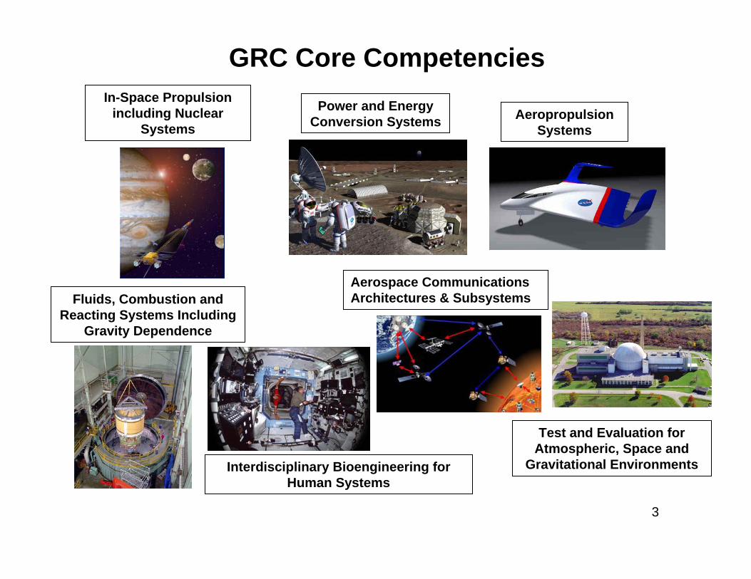
GRC Core CompetenciesPower and Energy
Conversion Systems
Test and Evaluation for Atmospheric, Space and
Gravitational EnvironmentsInterdisciplinary Bioengineering for Human Systems
Fluids, Combustion and Reacting Systems Including
Gravity Dependence
Aerospace Communications Architectures & Subsystems
In-Space Propulsion including Nuclear
SystemsAeropropulsion
Systems
3
4
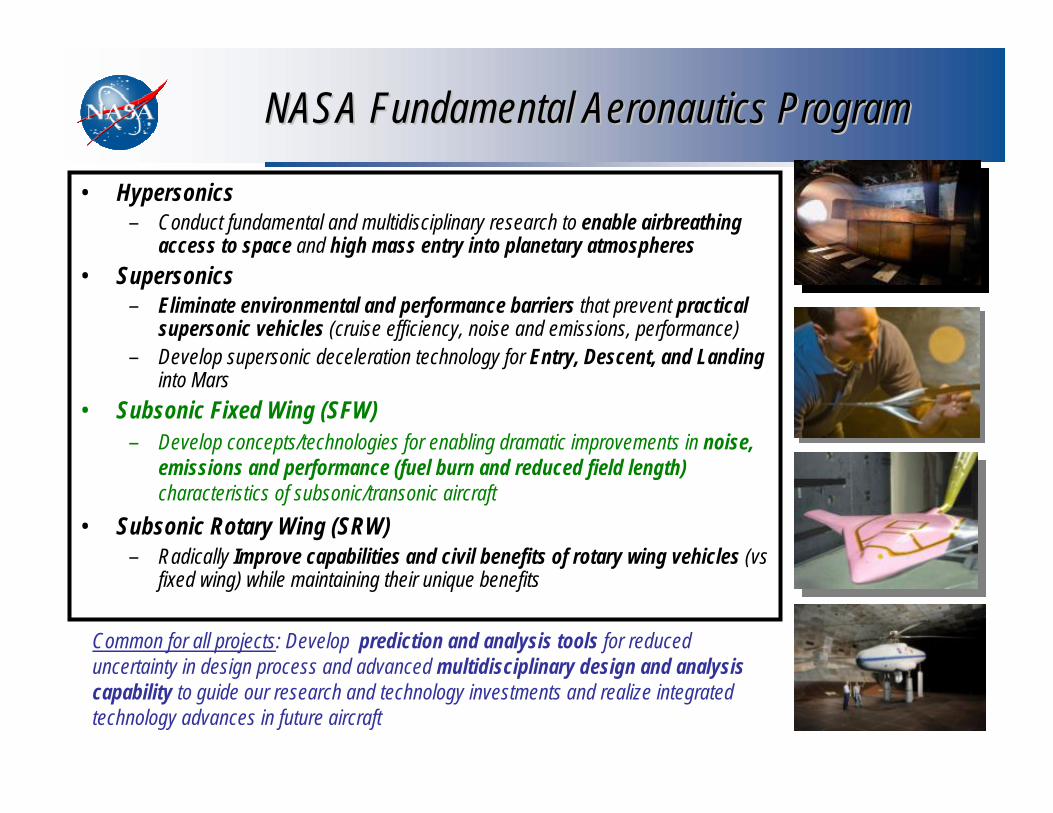
NASA Fundamental Aeronautics ProgramNASA Fundamental Aeronautics Program
• Hypersonics– Conduct fundamental and multidisciplinary research to enable airbreathing
access to space and high mass entry into planetary atmospheres• Supersonics
– Eliminate environmental and performance barriers that prevent practical supersonic vehicles (cruise efficiency, noise and emissions, performance)
– Develop supersonic deceleration technology for Entry, Descent, and Landinginto Mars
• Subsonic Fixed Wing (SFW)– Develop concepts/technologies for enabling dramatic improvements in noise,
emissions and performance (fuel burn and reduced field length)characteristics of subsonic/transonic aircraft
• Subsonic Rotary Wing (SRW)– Radically Improve capabilities and civil benefits of rotary wing vehicles (vs
fixed wing) while maintaining their unique benefits
Common for all projects: Develop prediction and analysis tools for reduced uncertainty in design process and advanced multidisciplinary design and analysis capability to guide our research and technology investments and realize integrated technology advances in future aircraft

1. "Greener Aviation" Technologies – including emission reduction and noise reduction technologies as used in the Federal Aviation Administration's Continuous Low Emissions, Energy and Noise (CLEEN) program, and the European Environmentally Friendly Engine (EFE) program and "Clean Sky" Joint Technology Initiative.2. Alternative Fuels – including biofuels, as promoted by the FAA's Commercial Aviation Alternative Fuels Initiative (CAAFI), and the recent FAA grant to the X Prize Foundation to spur development of renewable aviation fuels and technologies.3. High Speed Flight Technologies – such as supersonic and hypersonic aerodynamics, sonic boom reduction technology, and thermal management aids.4. Efficient Propulsion Technologies – including open rotors and geared turbofans, such as those used in the European DREAM (valiDation Radical Engine Architecture systeMs) program.5. Active Flow Technologies – such as plasma actuators.6. Advanced Materials – such as nanotechnology and composites.7. Active Structures – such as shape memory alloys, morphing, and flapping.8. Health Management – such as monitoring, prognostics, and self-healing.9. Remote Sensing Technologies – including unmanned aerial vehicles and satellites such as thoseused in NASA's Global Earth Observation System of Systems (GEOSS) program.10. Advanced Space Propulsion Technologies – including plasma-based propulsion such as the Variable Specific Impulse Magnetoplasma Rocket, and solar sail technologies.
AIAA Top 10 Emerging Aerospace Technologies of 2009

List of Current and Emerging Propulsion Technologies at GRC
• SFW: Conventional Tube/Wing Architecture with podded installation (geared turbofan, very high bypass ratio, variable area nozzle concepts, etc). Address noise, emission, performance goals.
• Hybrid Wing Body/Blended Wing Body Propulsion. Embedded distributed propulsion systems. (Presents an interesting airframe/propulsion/controls integration issue)
• Distributed Turbo-Electric Propulsion.• Exoskeletal Engine Concept• Constant Volume Combustion: The Pulse Detonation Turbine Engine• Supersonic Propulsion: Mach 1.6-1.8, small business jets overland. Sonic boom mitigation, cruise
emissions, fuel efficiency, noise reduction goals. Commercial jet at Mach1.8-2.0, variable cycle propulsion system, cruise emissions, fuel efficiency, etc
• PDE’s• Supersonic Retropropulsion Technology for Mars Entry, Descent and Landing• Hypersonic propulsion:Combined-cycle (turbo-ram-scram) engines (TBCC)• Hypersonic propulsion: MHD-Controlled Turbojet• RBCC: Trailblazer RBCC Engine Flow-path• Electric Propulsion: Next Generation Ion Engine Thruster Technology, NASA’s Evolutionary
Xenon Thruster (NEXT), HiVHAC• Radioisotope Electric Propulsion (REP):• Chemical Propulsion: Non-toxic Fuels, LOX-Methane, LOX-hydrogen. – (in-situ lunar regolith
resource). • Others: (Aerocapture, Solar Sails, Plasma Sails, Advanced Chemical Fuels Development, Solar
thermal propulsion, etc)6

Subsonic Fixed Wing System Level MetricsSubsonic Fixed Wing System Level Metrics……. technology for improving . technology for improving noisenoise, , emissionsemissions, , & performance& performance
Approach- Enable Major Changes in Engine Cycle/Airframe Configurations - Reduce Uncertainty in Multi-Disciplinary Design and Analysis Tools and Processes - Develop/Test/ Analyze Advanced Multi-Discipline Based Concepts and Technologies
Noise
-60% -75% better than -75%
-33%** -40%** better than -70%
-33% -50% exploit metro-plex* concepts
N+1 (2015)***Generation
Conventional Configurations relative to 1998 reference
N+2 (2020)***Generation
Unconventional Configurations relative to 1998 reference
N+3 (2025)***Generation
Advanced Aircraft Conceptsrelative to user-defined reference
LTO NOx Emissions (below CAEP 6)
Performance:Aircraft Fuel Burn
Performance:Field Length
-32 dB (cum below Stage 4)
-42 dB (cum below Stage 4)
-71dB (cum below Stage 4)
CORNERS OF THE TRADE SPACE
***Technology Readiness Level for key technologies = 4-6** Additional gains may be possible through operational improvements* Concepts that enable optimal use of runways at multiple airports within the metropolitan area

Inlet Flow Distortion Sensitivity and Stability
Tip Leakage Flows in High Pressure Ratio Cores
Combustor/Cooled Turbine Interaction
Endwall Contouring
Turbine Tip Flows
Highly Loaded Low Pressure Turbines
Technologies identified and ranked by NASA-led technical working group (TWG) consisting of representatives from industry, university & government agencies.
Set of white papers prepared by TWG
Top-Ranked Turbomachinery Technology Challenges
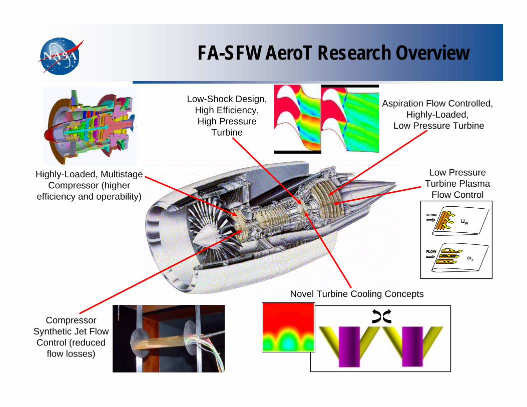
FA-SFW AeroT Research Overview
Highly-Loaded, Multistage Compressor (higher
efficiency and operability)
Low-Shock Design, High Efficiency, High Pressure
Turbine
Aspiration Flow Controlled, Highly-Loaded,
Low Pressure Turbine
Compressor Synthetic Jet Flow Control (reduced
flow losses)
Low Pressure Turbine Plasma
Flow Control
FLOW
ωz
FLOW
ωz
UW
FLOW
UW
FLOW
Novel Turbine Cooling Concepts

B-B
A-A
A A
B B
FLOW
X
Z
Experimental Study on Flow Control over a Blade by Acoustic Excitation (Synthetic Jets)
Typical Stator Wake Loss Reductionas a Function of Increasing Momentum Coefficient
Synthetic Jet in Axial Compressor stator blade
-25.0%
-20.0%
-15.0%
-10.0%
-5.0%
0.0%
0.000000 0.002000 0.004000 0.006000 0.008000 0.010000 0.012000
M o ment um C o ef f icient
Momentum Coefficient
Loss
Red
uctio
n
10% to 20% reduction in aerodynamic loss achieved with zero net mass flow devices
Turbomachinery Flow Control Development
Mean velocity contours:

INSULATOR
ELECTRODE
ELECTRODE
DBD PLASMA
Electrode perpendicular to flow
Active Flow Control via
Oscillating wall jet
FLOW
UW
Electrode parallel to flow
Active Flow Control via
Streamwise vortices
FLOW
ωz
Flow Control Using Dielectric Barrier Discharge Plasma Actuators – Round 1 NRAs
Advantages of GDP actuators:• Pure solid state device • Simple, no moving parts• Flexible operation, good for varying
operating conditions • Low power• Heat resistance – w/ proper materials
APPLIED VOLTAGE
“WIND”
2.7 5.3 8.0 10.7
10
20
30
40
Force, mN/m
Bias Voltage, p-to-p, kV
PRR
, kH
z
0
1.500
3.000
4.500
6.000
7.500
9.000
10.50
12.00
0 10 20 30 40 50
0
1
2
3
4
5
6
7
8
9
10
11
12
Bias Voltage, p-to-p, kV
Forc
e, m
N/m
PRR, kHz
1.4 2.7 4.0 5.3 6.7 8.0 9.3 10.7 11.0
Princeton Nanosecond Pulsing NRALarge force induced with voltage bias
Force Versus Pulse Repetition Rate & Bias

Blended Wing Body (BWB) Aircraft: Aerodynamic and Propulsion Benefits and Challenges (I)
CURRENT ARCHITECTURE:Blended Wing Body with Boundary-Layer Ingestion Inlets/Nacelles: Reduced ram drag, lower wetted area, lower structural weight, etc
Anticipated Benefits:Large aerodynamic efficiency (L/D)
Reduced Noise
Reduced fuel burn benefits to HWB aircraft with embedded engines implies reduced emissions.
Challenges:No Tail: stability and control a critical issue ((statically unstable and may need active flight control (B2))
Non-circular fuselage cross-section
Inlet Flow Distortion problems
Propulsion/Airframe Integration: Engines mounted above upper surface near trailing edge. Interactions between WING, ENGINES, and CONTROL surfaces introduce design complexity.
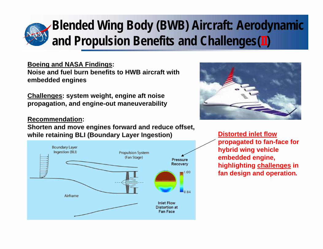
Blended Wing Body (BWB) Aircraft: Aerodynamic and Propulsion Benefits and Challenges(II)
Distorted inlet flow propagated to fan-face for hybrid wing vehicle embedded engine, highlighting challenges in fan design and operation.
Boeing and NASA Findings:Noise and fuel burn benefits to HWB aircraft with embedded engines
Challenges: system weight, engine aft noise propagation, and engine-out maneuverability
Recommendation:Shorten and move engines forward and reduce offset, while retaining BLI (Boundary Layer Ingestion)

14
Core/Combustor TechnologyLow NOx combustor concepts for high OPR environmentIncrease thermal efficiency without increasing NOx emissions
• Improved fuel-air mixing to minimize hot spots that create additional NOx• Lightweight liners to handle higher temperatures associated with higher OPR• Fuel Flexibility
• DoD HEETE Program is developing higher OPR compressor technology…. ERA will focus on new combustor technology for reduced NOx formation
Injector Concepts• Partial Pre-Mixed• Lean Direct Multi-Injection
Enabling Technology• lightweight CMC liners• advanced instability controls
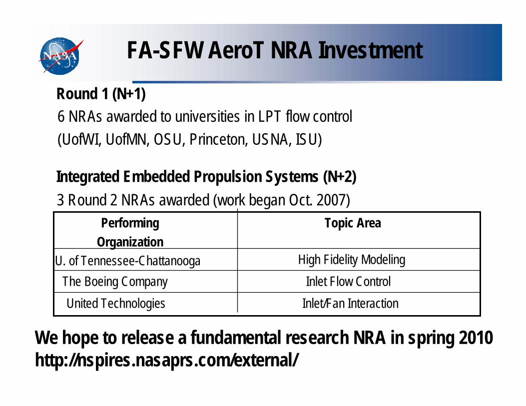
FA-SFW AeroT NRA Investment
6 NRAs awarded to universities in LPT flow control (UofWI, UofMN, OSU, Princeton, USNA, ISU)
Integrated Embedded Propulsion Systems (N+2)
Inlet/Fan InteractionUnited TechnologiesInlet Flow ControlThe Boeing Company
High Fidelity ModelingU. of Tennessee-Chattanooga
Topic AreaPerformingOrganization
3 Round 2 NRAs awarded (work began Oct. 2007)
Round 1 (N+1)
We hope to release a fundamental research NRA in spring 2010http://nspires.nasaprs.com/external/

Airbreathing Hypersonic Propulsion
• Hypersonic Propulsion (Turbine‐Based Combined Cycle (TBCC) Propulsion, Mode Transition, Bleed Modeling, Aero‐servo‐thermoelastic issues in hypersonics, Fuels, etc
16

Propulsion Technical Challenges• Design and Analysis Tool Development
– Improvement and validation in the areas of: 1) CFD tools concentrating on RANS modeling addressing combustion, LES, and other algorithms emphasizing combustion physics (steady and unsteady), 2) engineering level performance and design tools concentrating on cycle performance tools, scaling techniques, and system weight algorithms, and 3) multidisciplinary tools including conjugate problems in aerodynamics, heat transfer, and mechanical loads.
• Fundamental Propulsion Physics & Modeling– Acquire comprehensive data sets for the development of physical models, relevant to problems unique to hypersonic propulsion-
aerodynamic physics and analysis, e.g. turbulent combustion, flame holding and ignition. • Propulsion Materials & Structures
– Improve life and durability, achieve weight and volume reduction of structural components and enhance life prediction tools for high-speed propulsion systems.
• Propulsion / Airframe/ Controls Integration– Address the integrated performance, control and coupled-design issues of the entire propulsion-airframe entity inclusive of
ground to flight performance extrapolation techniques.• Scramjet / Ramjet Propulsion
– Improve the characterization of: (a) fuel-air mixing, flame holding, ignition and turbulent flame propagation (in relevant scramjet and ramjet environments), (b) the mode transition mechanisms, control thereof and relevant fluid-dynamics of airbreathing propulsion inclusive of shock interactions, (c) the quantification of hypervelocity propulsive physics, with particular emphasis on the ultra-high-speed performance aspects of the scramjet, inclusive of LOX addition.
• High–Mach Turbine Propulsion– Quantify and address the critical technical barriers of high-Mach turbine flow path inclusive of those pertaining to the inlet,
variable cycle turbine engine, after-burner / hyper-burner, nozzle, and the interactions between these components. • Turbine Based Combined Cycle Propulsion AND Mode Transition
– Address issues associated with the integration of a turbine engine with an adjacent scramjet flowpath in a turbine-based combined-cycle (TBCC) propulsion system inclusive of vehicle integration.
• Rocket Based Combined Cycle Propulsion– Address challenges associated with the high degree of integration of the rocket component with the airbreathing flowpath to
improve performance, system structural efficiency and thrust-to-weight. Explore the integration of advanced rocket cycles. • Advanced Concepts
– Explore advanced hypersonic propulsion concepts including, but are not limited to, magnetohydrodynamics, novel combustor designs, advanced thermal management, advanced sensor development, advanced engine controls, and advanced fuels.
17

THE TECHNOLOGY OF “INTEGRATION”• AIRFRAME-PROPULSION-CONTROLS INTEGRATION: The need to carefully
integrate the propulsion system with the vehicle airframe for optimum overall performance is a fundamental requirement of air-breathing hypersonic vehicles.
• The “technology of integration” is of unique significance in the development of hypersonic vehicles where each component affects every other component. Unfortunately, engineering practice usually leads to a subdivision by components in the design, development, and manufacturing processes; so that the “technology of integration” is not well-advanced. Consequently, the development of a hypersonic vehicle requires an investigation and demonstration of an integrated design.
• Thermal management and structural integration are other aspects of the integration problem. Thermal management is critical to defining a practical hypersonic vehicle concept since the fuel is usually the only hest sink available at hypersonic speed.
• PAI is a highly non-linear phenomenon. There are some vehicle design issues that are sufficiently complex and dependent in some unknown way on scale that they may not be reliably resolved even by combining test results from a number of separate facilities.
• CRITICAL TECHNOLOGIES IN AIRFRAME/PROPULSION INTEGRATION(1) MISSION/CONFIGURATION CONSTRAINTS (Alternate Concepts)(2) FLOW-PATH OPTIMIZATION(3) INSTALLED PERFORMANCE ASSESSMENT
18

19Hypersonic FY10 workshop July 21-23, 2009
High Mach Turbine
Dual Inlet
ScramjetInlet Bleed Pipes
Facility Strut Mount
High Mach Turbine
Dual Inlet
ScramjetInlet Bleed Pipes
Facility Strut Mount
High Mach Turbine
Dual Inlet
ScramjetInlet Bleed Pipes
Facility Strut Mount
Hypersonic Project
TBCC Technology Development
(I) TBCC Propulsion System Development
(II) MODE TRANSITION for TBCC Engines – a dynamicphenomenon. (From Turbojet to Ram/Scram and return)
www.nasa.gov 20
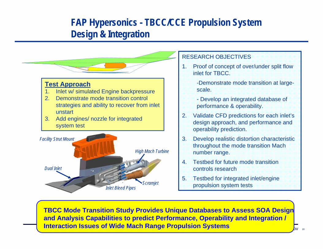
RESEARCH OBJECTIVES
1. Proof of concept of over/under split flow inlet for TBCC.
-Demonstrate mode transition at large-scale.
- Develop an integrated database of performance & operability.
2. Validate CFD predictions for each inlet’s design approach, and performance and operability prediction.
3. Develop realistic distortion characteristic throughout the mode transition Mach number range.
4. Testbed for future mode transition controls research
5. Testbed for integrated inlet/engine propulsion system tests
TBCC Mode Transition Study Provides Unique Databases to Assess SOA Design and Analysis Capabilities to predict Performance, Operability and Integration / Interaction Issues of Wide Mach Range Propulsion Systems
Test Approach1. Inlet w/ simulated Engine backpressure2. Demonstrate mode transition control
strategies and ability to recover from inlet unstart
3. Add engines/ nozzle for integrated system test
High Mach Turbine
Dual Inlet
ScramjetInlet Bleed Pipes
Facility Strut Mount
FAP Hypersonics - TBCC/CCE Propulsion System Design & Integration
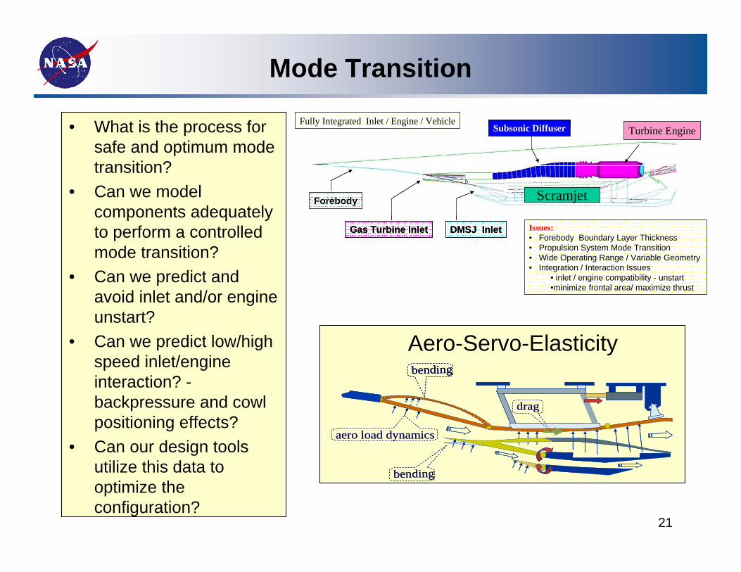
Mode Transition
• What is the process for safe and optimum mode transition?
• Can we model components adequately to perform a controlled mode transition?
• Can we predict and avoid inlet and/or engine unstart?
• Can we predict low/high speed inlet/engine interaction? -backpressure and cowl positioning effects?
• Can our design tools utilize this data to optimize the configuration?
21
Forebody
Gas Turbine Inlet DMSJ Inlet
Subsonic Diffuser
Forebody
Gas Turbine Inlet DMSJ Inlet
Subsonic Diffuser
Issues:• Forebody Boundary Layer Thickness• Propulsion System Mode Transition• Wide Operating Range / Variable Geometry• Integration / Interaction Issues
• inlet / engine compatibility - unstart•minimize frontal area/ maximize thrust
Fully Integrated Inlet / Engine / Vehicle
Scramjet
Turbine Engine
aero load dynamics
bending
bending
drag
aero load dynamics
bendingbending
bending
drag
Aero-Servo-Elasticity
October 7-9, 2008 FAP Annual Meeting - Hypersonics Project 22
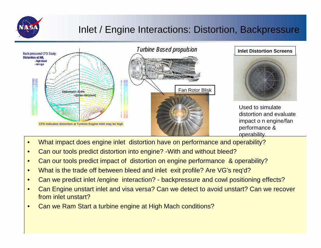
BackBack--pressured CFD Study: pressured CFD Study: Distortion at M4,Distortion at M4,
-- high bleedhigh bleed-- no no v.g.sv.g.s
CFD indicates distortion at Turbine Engine Inlet may be high
Distortion=~8.6%Distortion=~8.6%=[(max=[(max--min)/min)/aveave]]
BackBack--pressured CFD Study: pressured CFD Study: Distortion at M4,Distortion at M4,
-- high bleedhigh bleed-- no no v.g.sv.g.s
CFD indicates distortion at Turbine Engine Inlet may be high
BackBack--pressured CFD Study: pressured CFD Study: Distortion at M4,Distortion at M4,
-- high bleedhigh bleed-- no no v.g.sv.g.s
BackBack--pressured CFD Study: pressured CFD Study: Distortion at M4,Distortion at M4,
-- high bleedhigh bleed-- no no v.g.sv.g.s
CFD indicates distortion at Turbine Engine Inlet may be high
Distortion=~8.6%Distortion=~8.6%=[(max=[(max--min)/min)/aveave]]
Inlet Distortion ScreensTurbine Based propulsion Turbine Based propulsion
Fan Rotor Blisk
• What impact does engine inlet distortion have on performance and operability? • Can our tools predict distortion into engine? -With and without bleed?• Can our tools predict impact of distortion on engine performance & operability? • What is the trade off between bleed and inlet exit profile? Are VG's req'd?• Can we predict inlet /engine interaction? - backpressure and cowl positioning effects?• Can Engine unstart inlet and visa versa? Can we detect to avoid unstart? Can we recover
from inlet unstart?• Can we Ram Start a turbine engine at High Mach conditions?
Used to simulate distortion and evaluate impact o n engine/fan performance & operability.
Inlet / Engine Interactions: Distortion, Backpressure

ELECTRIC PROPULSION
23
24

25
26

27
28

29
NOVEL AIRBREATHING ENGINE CONCEPTS
(1) EXOSKELETAL ENGINE
(2) MHD-TURBOJET ENERGY BYPASS ENGINE
(MHD-CONTROLLED TURBOJET)
30

EXOSKELETAL ENGINE CONCEPT (ESE)
• Consist of a DRUM ROTOR with rotating blades mounted inside serving the usual functions of fan, compressor, and turbine.
• Rotor blades are carried in COMPRESSION by the rotating outer casing.• Eliminates the shafts and discs and creates an OPEN channel along engine centerline
- - a unique feature that may be exploited for a variety of purposes.• Drum rotor design driven by ability to use light-weight materials, CMC materials for
higher temperatures. • Opportunities for research in basic design rules and an understanding of design
methods for this concept. Identify technology barriers that must be resolved to enable the ESE.
• Many potential advantages: Significant reduction in overall system weight with a corresponding increase in thrust to weight ratio, elimination of bore stresses in rotating components, increased HCF life for blades, enhanced containment capabilities for greater safety of aircraft and passengers, etc
• USES of CENTER DUCT: (1) Ramjet Duct – translating center-body for operation to Mach 5. Somewhat similar to J-58 (SR-71) turbine bypass system. Research and simulation opportunities in inlet operation, mode transition, (2) PDE (3) Noise reduction – inverted velocity profile. Preliminary analysis has begun to quantify the benefits. This is an area of research that invites further study.(4) Fuel Storage - cruise missile application 31

EXOSKELETAL ENGINE CONCEPT: Cutaway Views
32

33
3/2000 Rapid Prototype -Solano
Sleeve Bearings

34
8/2001 Rapid Prototype -Blaser
Ball Bearings

35
2/2001 Rapid Prototype –Blaser
Ball Bearings

Ramjet Only
Turbojet & RamjetTurbojet Only
Turbojet InletCompressor
Burner
Turbine
Ramjet Burner Ramjet Nozzle
Turbojet NozzleTurbojet Exhaust Duct & Afterburner
Ramjet Mode (Mach 3 – 5)
Figure 1: Exoskeletal Mach 5 Turboramjet Concept
Diameter-------------22 inchesLength--------------112 inches
Inlet Maximum AreasTurbojet-------------130 sq inRamjet---------------364 sq in
Fig: 1a
Fig: 1b
36

“The New Kid on the Block”PLASMA/MHD Flow Control/Propulsion
2 TYPES OF PLASMA:
(1) WEAKLY-IONIZED PLASMA (WINP)These are artificially generated COLD plasmas via various methods(Fast Ionization Wave (FIW) method). Electron temperature about 1-2 eV (up to 30,000K), Gas temperature about 600K (max), etc. Plasma can be highly localized in flow-field.
(2) REENTRY PLASMAS (Nature’s mandate)Generally fully-ionized in shock layer (gas-cap) of reentry vehicles. Gas temperatures to 20,000K (Apollo 13, Mach 35 at start of entry).
GRC Interests and Efforts:
(1)Plasma Assisted Ignition and Combustion
(2)Hydrocarbon Fuel Reforming
(3)MHD-Controlled turbojet ( Magnetogasdynamic Power Extraction and Flow Conditioning in a Gas Turbine) 37

General Arrangement of MHD-Controlled turbojet
High-Speed Propulsion
GOAL: Extend the operating range of a jet engine to Mach 738
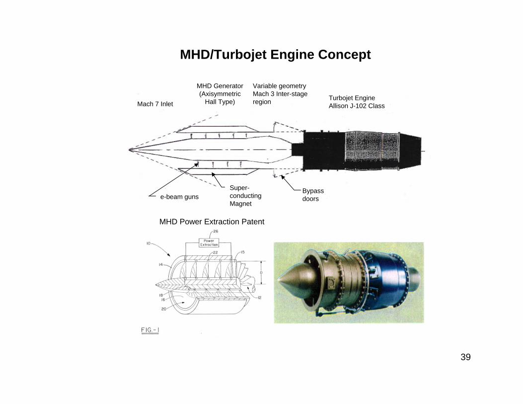
Mach 7 Inlet
MHD Generator (Axisymmetric
Hall Type)
Variable geometry Mach 3 Inter-stage region Turbojet Engine
Allison J-102 Class
Super-conducting Magnet
e-beam gunsBypass doors
MHD/Turbojet Engine Concept
MHD Power Extraction Patent
39
0
200
400
600
800
1000
1200
1400
0 0.2 0.4 0.6 0.8 1 1.2
Entropy (kJ)
Tem
pera
ture
(K)
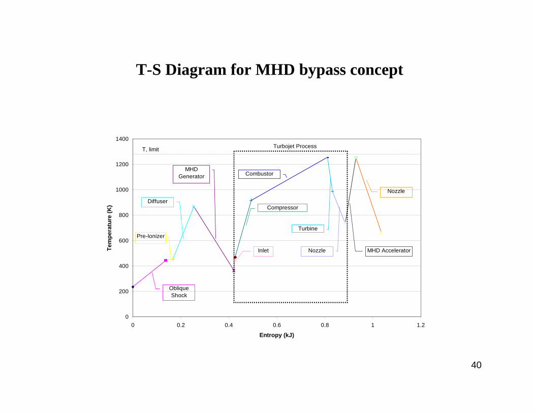
Oblique Shock
MHD Generator
Diffuser
Pre-Ionizer
Nozzle
MHD AcceleratorNozzle
Turbine
Combustor
Compressor
Inlet
Turbojet ProcessT, limit
T-S Diagram for MHD bypass concept
40

Annular Hall Type MHD Generator for Use with a Turbojet
(Based on Hall Thruster Design for Space: E-beam Ionization, or pulsed FIW techniques ~ preferred)
US patent (6,696,774 B1; 2004). Issued to GRC (Blankson and Schneider).
41

Preliminary ResultsMHD Bypass Engine Application –OSU Evaluation
•OSU quasi-1D, nonequilibrium MHD air flow code used
•Ionization by uniformly distributed e-beam
•Realistic E-beam power 0.11 MW (20 keV electron beam, 0.2 mA/cm2)
•10 Tesla magnetic field
0.0 0.2 0.4 0.6 0.8 1.0 1.2 1.41.0
1.5
2.0
2.5
3.0
E-beam power, MW
Exit Mach number
0.0 0.2 0.4 0.6 0.8 1.0 1.2 1.40
2
4
6
8
10
E-beam power, MW
Power, MW
Electric power output
Kintetic energy reduction
•Substantial reduction in the kinetic energy of supersonic flow is possible
•50% Conversion of kinetic energy to electrical power predicted 42
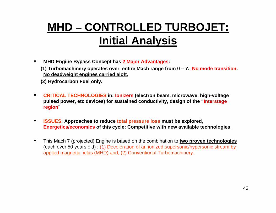
MHD – CONTROLLED TURBOJET: Initial Analysis
• MHD Engine Bypass Concept has 2 Major Advantages: (1) Turbomachinery operates over entire Mach range from 0 – 7. No mode transition. No deadweight engines carried aloft.
(2) Hydrocarbon Fuel only.
• CRITICAL TECHNOLOGIES in: Ionizers (electron beam, microwave, high-voltage pulsed power, etc devices) for sustained conductivity, design of the “Interstage region”
• ISSUES: Approaches to reduce total pressure loss must be explored, Energetics/economics of this cycle: Competitive with new available technologies.
• This Mach 7 (projected) Engine is based on the combination to two proven technologies(each over 50 years old) : (1) Deceleration of an ionized supersonic/hypersonic stream by applied magnetic fields (MHD) and, (2) Conventional Turbomachinery.
43

Opportunities for Research (Plasma/MHD)!• Innovative research needed to continue advances in component development as well as to be able
to control the hypersonic environment within, on and near the vehicle, e.g. thermal management systems.
• New design variables for the 21st Century based on our ability to exploit: flowfield electrical and magnetic properties, take advantage of interdisciplinary synergies
--- Plasma Devices (plasma and applied electromagnetic fields). Vehicle control using plasmas. Shock-wave control.
--- MHD (Magnetohydrodynamic) Flow manipulation (Russian AJAX). Ability to extract energy from flowfield and use it as an asset, not a liability.
• High Energy-Density Fuels for airbreathing engines.• Dramatically lighter, more durable, high temperature TPS (thermal protection systems).• Control of boundary layer transition: use of non-conventional methods.• Develop Accurate and Efficient Simulation of Hypersonic flows with Plasma/MHD/Chemistry.
Nonequilibrium molecular multi-temperature (no-thermal) plasma flow models (computational code) incorporating key processes of charged species production and removal, a master equation for the vibrational levels of diatomic molecules, a Boltzmann equation for plasma electrons, and a Poisson equation for the electric field. Ohm’s law to include, ion slip effects, Hall currents, and electron pressure gradients.
44

NASA Glenn University Student & Faculty Opportunities
LERCIP (Lewis' Educational and Research Collaborative Internship Program)
Undergraduate & Graduate Students
January 31 Application Deadline
MUST (Motivating Undergraduates in Science & Technology Program)
Focused on engaging students from underserved and underrepresented groups
February 2 Application Deadline
GSRP (Graduate Student Research Program)
January 31 Application Deadline
USRP (Undergraduate Student Research Program)
January 31 Application Deadline (summer session)
February 29 Application Deadline (fall session)
October 22 Application Deadline (spring session)
NGFFP (NASA Glenn Faculty Fellowship Program)
February 15 Application Deadline
http://www.nasa.gov/offices/education/programs/index.html

46

Summary and Conclusions• GRC is aligned with and focused on achieving NASA mission success.
• GRC has a unique combination of talented people and one-of-a-kind facilities & tools, well aligned to our eight interdisciplinary core competencies.
• Our core competencies have positioned us to strategically encourage and accommodate further partnerships and investment.
• NUMEROUS COLLABORATIVE RESEARCH OPPORTUNITIES EXIST.
• Opportunities exist in Aero and Space, across the Mach number range.
47

BACKUP SLIDES
48
MHD Energy Bypass with a Conventional Turbojet:MAGNETOGASDYNAMIC POWER EXTRACTION AND FLOW CONDITIONING FOR A GAS TURBINE
(In partnership with Ohio State University.) !!!
This Mach 7 (projected) Engine (an AJAX-like development) is based on the combination to two proven technologies(each over 50 years old) : (1) Deceleration of an artificially-ionized supersonic/hypersonic stream by applied magnetic fields (MHD) and, (2) Turbomachinery.
Note that the turbomachine operates over the entire Mach number range (0-7) (ie. no dead-weights, no mode-transition!).
Additional Information is available at:(1) AIAA Paper 2003-6922, presented at 12th AIAA International Space Planes and
Hypersonic Systems Conference, 15-19 December, 2003/Norfolk, VA.(2) S.N.B. Murthy and I.M. Blankson, “MHD Energy Bypass for Turbojet-Based
Engines”, IAF-00-5-5-05, presented at 51st International Astronautical Congress, October 2-6, 2000, Rio de Janeiro, Brazil
(3) “Magnetogasdynamic Power Extraction and Flow Conditioning for a Gas Turbine”, AIAA Paper 2003-4289 (Also NASA/TM – 2003-212612).
(4) US Patent (6,696,774 B1, 2004) Magnetogasdynamic Power Extraction and Flow Conditioning in a Gas Turbine. (Issued to Blankson and Schneider) 49
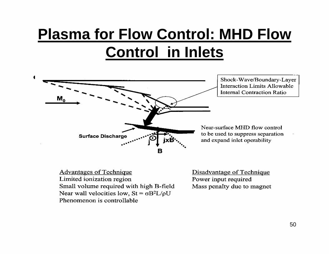
Plasma for Flow Control: MHD Flow Control in Inlets
• (U)
50

Plasma Assisted Combustion(Ignition, Combustion, Fuel Reforming).
• Minimize energy required for ignition and flame stabilization, expand combustion limits
• Provide volumetric ignition (off-wall)• Thermal vs Non-equilibrium processes• Various mechanisms are being investigated: plasma jet generators,
microwave torches, pulsed nanosecond discharges, RF discharges, microwave assisted combustion, surface microwaves, subcrirical microwaves, etc.
Ideal Scramjet
51
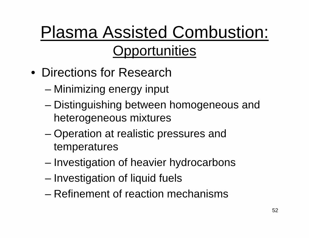
• Directions for Research– Minimizing energy input – Distinguishing between homogeneous and
heterogeneous mixtures– Operation at realistic pressures and
temperatures– Investigation of heavier hydrocarbons– Investigation of liquid fuels– Refinement of reaction mechanisms
Plasma Assisted Combustion: Opportunities
52

MHD/PLASMA: POTENTIAL APPLICATIONS
• Turbomachinery-based MHD Energy bypass engines: extends the operating range of gas-turbines to Mach 7. (Energy Extraction)
• Jet noise reduction• Aerodynamic drag and heat transfer reduction of aerospacecraft• Localized control of hypersonic separated flows, flow control of hypersonic
inlets, mitigation of off-design issues for airbreathers, etc• Rearrangement of thermal and mechanical loads on structural elements of
aircraft • Steering/maneuvering of aircraft by electromagnetic forces and moments• Sonic boom mitigation• Control of high altitude (rarefied environment) vehicles: replacement of RCS with
plasma actuators.• CEV: Applications in Martian atmosphere• CEV: Lunar dust mitigation and control• PLASMA-ASSISTED IGNITION/COMBUSTION• SPACE SITUATIONAL AWARENESS:Track/ID unknown reentry vehicle from
EM signature• ANTI-RADAR CLOAKING• Protection against RF MICROWAVE radiation
53

OBJECTIVES:(1) Establish the feasibility and demonstrability of kinetic energy bypass from the inlet air stream
of a jet engine. This energy bypass is accomplished using weak ionization of the inlet stream by an external means and MHD interaction with the ionized gas. The engine consists of an existing commercial or military jet engine preceded by an MHD power extractor. The jet engine may be a turbojet (e.g. Allison J-102) or a ramjet, individually, or in various combined configurations. The MHD power generator is a novel GRC invention (Patent pending). The resulting engine is a revolutionary power-plant capable of flight at Mach 7.
(2) Develop a MHD CE/SE code capable of computing viscous compressible MHD flows with real-gas effects. The CE/SE method requires no special treatment to maintain the divergence-free condition on the magnetic field. (Regarding the methodologies used for solving MHD equations, the finite difference and the finite volume methods based on the flux-vector splitting or the approximate Riemann solvers occupy the dominant position. The main difficulty in these methods is the imposition of the divergence-free condition div B = 0 for the magnetic field, which results in a loss of the hyperbolicity of the ideal MHD equations. Violating the div B = 0 constraint leads to loss of momentum and energy conservation.)
(3) Ultimate goal is to establish a competitive capability in MHD/Plasma Technology for aerospace applications.
54

Cycle Model of Turbofan Engine with MHD
55

Experimental Method for Conducting an Engine Test
56

FUTURE PLASMA/MHD RESEARCH
• Innovative research needed to continue advances in component development as well as to be able to control the hypersonic environment within, on and near the vehicle, eg. thermal management systems.
• New design variables for the 21st Century will be based on our ability to exploit: flowfield electrical and magnetic properties, take advantage of interdisciplinary synergies
--- Plasma Devices (plasma and applied electromagnetic fields). Vehicle control using plasmas. Shock-wave control.
--- MHD (Magnetohydrodynamic) Flow manipulation (Russian AJAX). Ability to extract energy from flowfield and use it as an asset, not a liability.
• High Energy-Density Fuels for airbreathing engines• Dramatically lighter, more durable, high temperature TPS (thermal protection systems).• Control of boundary layer transition.• IONIZER – research into more efficient, low cost and low-weight ionizers. • Applications of MHD to Reentry Vehicle Control – Extreme high temperatures and heat transfer
rates in shock layer of blunt-nosed hypersonic vehicle.• Ionization and subsequent conductivity of air in shock layer –natural to consider electromagnetic
control of this class of flows.• Prior analytical work indicates: a magnetic field applied to this conductive shock layer could use the
Lorentz force to increase drag (by opposing fluid motion) of vehicle, and by slowing the flow near the surface, reduce heat transfer and skin friction.
• Old Proposed Example – MAGNETIC FLAP on Apollo capsule – electromagnetic coil used to produce lift and control moments. 57

MAGNETOGASDYNAMIC POWER EXTRACTION:
OSU Nonequilibrium Flow Code
•Master equation for vibrational populations of N2 and O2
•Boltzman equation for electrons
•Nonequilibrium air chemistry including ion-molecule reactions
•Nonequilibrium electron kinetics (ionization, recombination, andattachment)
•One-dimensional gas dynamics
•Generalized Ohm’s law
•Validated by comparing with electric discharge, shock tube, and MHD experiments
Details in AIAA 2003-4289 58
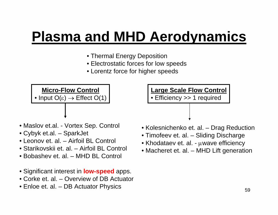
Plasma and MHD Aerodynamics
Micro-Flow Control• Input O(ε) → Effect O(1)
Large Scale Flow Control• Efficiency >> 1 required
• Thermal Energy Deposition• Electrostatic forces for low speeds• Lorentz force for higher speeds
• Maslov et.al. - Vortex Sep. Control• Cybyk et.al. – SparkJet• Leonov et. al. – Airfoil BL Control• Starikovskii et. al. – Airfoil BL Control• Bobashev et. al. – MHD BL Control
• Significant interest in low-speed apps.• Corke et. al. – Overview of DB Actuator• Enloe et. al. – DB Actuator Physics
• Kolesnichenko et. al. – Drag Reduction• Timofeev et. al. – Sliding Discharge• Khodataev et. al. - µwave efficiency• Macheret et. al. – MHD Lift generation
59

MHD Energy Bypass with a Conventional Turbojet:MAGNETOGASDYNAMIC POWER EXTRACTION AND FLOW CONDITIONING FOR A GAS TURBINE
(In partnership with Ohio State University.) !!!
This Mach 7 (projected) Engine (an AJAX-like development) is based on the combination to two proven technologies(each over 50 years old) : (1) Deceleration of an artificially-ionized supersonic/hypersonic stream by applied magnetic fields (MHD) and, (2) Turbomachinery.
Note that the turbomachine operates over the entire Mach number range (0-7) (ie. no dead-weights, no mode-transition!).
Additional Information is available at:(1) AIAA Paper 2003-6922, presented at 12th AIAA International Space Planes and
Hypersonic Systems Conference, 15-19 December, 2003/Norfolk, VA.(2) S.N.B. Murthy and I.M. Blankson, “MHD Energy Bypass for Turbojet-Based
Engines”, IAF-00-5-5-05, presented at 51st International Astronautical Congress, October 2-6, 2000, Rio de Janeiro, Brazil
(3) “Magnetogasdynamic Power Extraction and Flow Conditioning for a Gas Turbine”, AIAA Paper 2003-4289 (Also NASA/TM – 2003-212612).
(4) US Patent (6,696,774 B1, 2004) Magnetogasdynamic Power Extraction and Flow Conditioning in a Gas Turbine. (Issued to Blankson and Schneider) 60

61
Technology Maturation Perspective on SFW and ERA ProjectsTechnology Maturation Perspective on SFW and ERA Projects
TRL NASA Definition (NPR 7120.8)
9 Actual system flight proven through successful mission operations
8 Actual system completed and “flight qualified”through test and demonstration
7 System prototype demonstrated in operational environment
6 System/sub-system model or prototype demonstrationin relevant environment
5 Component and/or breadboard validation in relevant environment
4 Component and/or breadboard test in laboratory environment
3 Analytical and experimental critical function,and/or characteristic proof-of-concept
2 Technology concept and/or application formulated
1 Basic principles observed and reported
ERAProject
SFW Project(other fundamental)

62
Propulsion Airframe Integration
Lord, Sepulveda, et al
Fuel Burn Fuel Burn
Fan Diameter
Noise
(Higher FPR) (Lower FPR)Low
High
Noise
TSFC
Fuel Burn
GTFAdv GTF~ 2018
Weight& Drag
Turbofan
PAI Challenges Increase
UHB Installation that minimizes or avoids performance penaltiesIncreased size of system may drive need for alternate configurations
• Increasingly large diameters present increasingly difficult installations for conventional low wingconfigurations, and may require alternate configurations/installations to take advantage ofpropulsive efficiency
…. significant vehicle level trade space to explore

Proposed Task ApproachApproach; The overall objective requires the accomplishment of several tasks: (2-year research and 2-year build and test follow-on).1. CE/SE MHD Code development for multidimensional flows.2. CE/SE MHD Code development incorporating viscous and real-gas flows.3. Conduct cycle analyses to establish the operating conditions for a jet engine cycle, that are optimal for kinetic energy
transfer from inlet air to a downstream location in the engine.4. Establish a model for a jet engine with energy bypass for determining the design and operating conditions in which the
thrust-to-weight ratio, thrust per unit mass of fuel consumption, and effectiveness of energy utilization are maximized;
5. Establish the resulting engine thrust to weight ratio and thermodynamic efficiency, using electrical conductivity, magnet mass, and MHD energy conversion as some of the parameters. Conduct a preliminary design for the scheme.
6. Conduct laboratory scale tests to experimentally establish the efficiency of the MHD conversion of the kinetic energy of the externally ionized gas in the proposed scheme.
7. Outline a method of conducting a test on a jet engine for demonstrating and assessing the performance of a MHD energy bypass system incorporated into a jet engine. The jet engine under consideration is the existing Allison J-102
Relationship to Other Work and CollaborationsA preliminary assessment of this concept has shown feasibility. Major efforts are needed in the design of the ionizer. Theconcept is a novel approach for optimum design of combined-cycle engines that incorporate turbomachinery and MHD.This is essential to aeronautics and especially to Glenn Research Center because of the incorporation of turbine engine cycles into this integrated turbine-MHD configuration. The Power and On-board Propulsion Division has numerous programs in electric propulsion for in-space applications as well. This research is directly related to ongoing work in NASA and industry (see attachment) to develop both low-cost alternatives for access-to-space, and novel concepts for high Mach number propulsion an airframes exploiting MHD and plasmas. OSU: model and calculation scheme on a parametric basis for the interaction between a weakly ionized air stream and anapplied magnetic field, when the ionization is undertaken with different means (e.g. High – energy microwaves, electron beam,) SANDIA: Microwave ionization technology. IVTAN (Russia) Pulsed Microwave ionization.
63

Proposed Work for FY2003 –FY2006 (I)
• Year 1- Make improvements to CE/SE Code for viscous and 3-D flows and Test
MHDcodes using known results.
– Incorporate Boltzman and Poisson solvers in CNPD code– Develop master equations for vibrational levels of air– It is desired to develop in-house, a numerical capability (CFD code) to
simulate the above phenomena under a single code platform that combines electromagnetics and classical and real gas dynamics.
– Refine operating conditions for a MHD bypass turbo-jet cycle. – Development of INLET system for Bypass Engine from Mach 0 – 7.– In phase-I of this work we intend to study MHD interactions with inlet
processes in a simple two-dimensional or axi-symmetric geometries using CE/SE code.
– To formulate the technical conditions for the feasibility of the MHD Bypass engine cycle that incorporates a gas turbine powerplant. 64

APPLICATIONS SPECTRUM
TurbineEngines
Aircraft & Missiles• Mach 0-3
Today
TurbineEngines
Aircraft & Missiles• Mach 0-3
Today
Combined Cycle Engines (Cruise) w/Hydrocarbon/HydrogenPowered Scramjets
Hypersonic Intercept•Interceptor Mach 10+•100,000 ft Cruise
Mid-Term
LRC
Combined Cycle Engines (Accelerator)w/Hydrogen Powered Scramjets
Access to Space• Aircraft Mach 8-15• Orbit Flexibility• Increased Payload• 100,000 ft Cruise
Far-TermNear-Term
LRC
Fast Response Standoff Weapon• Rapid Response• Standoff (100’s of miles)• Mach 5-8 Scramjets• Mach 0-5 Turbine Accelerators
Turbine Accelerators
Hydrocarbon Scramjets
LRC
Rapid Strike / Recce Aircraft• Rapid Global Response• Increase Sortie Rate• Mach 5-10
NASA Spinoff Capabilities Naturally Support DoD Applications
65

Exoskeletal Engine Cutaway View
66

A FEW CHARACTERISTICS OF THE HYPERSONIC FLOW FIELD
• Definition of Hypersonic Flow: ----- Mach number(Velocity Energy/Temperature Energy) ~ M squared
• Energy in the Flowfield --- KE of Space Shuttle at Reentry =1/20th Energy of Hiroshima Bomb. KE is dissipated in about 15 minutes (ballistic entry). Could exploit “lifting reentry” but requires higher L/D.
• High stagnation temperatures, high heat transfer to vehicles, Viscous interaction, shock-boundary layer interaction… ( stagnation Enthalpy curve, Edney’s chart, X-15 Pylon)
• Real-gas effects (M > 8): Changes in gas characteristics around vehicles, changes in chemical constituents of air
• NEW PARADIGMS: (1) Speed, Global Range from CONUS– Airbreathing vehicles (Mach 0 - 10+?)– Transatmospheric options (Mach to 25)
(2) Thermal management for slender air-breathing vehicles.67

WHAT’S NEW! RESEARCH AND DEVELOPMENT FOR SUSTAINED AIRBREATHING HYPERSONIC FLIGHT
• COMPONENT OPERABILITY OVER ENTIRE MISSION MACH RANGE.
• Long-duration hypersonic flight for slender lifting vehicles.• Aerothermal load prediction methods and validation. Prediction of complex
shock-wave systems, shock/boundary layer interactions, wake interactions, flow separation interactions evolving spatially and temporary.
• Six -degree-of-freedom dynamic motion - hypersonic vehicle maneuverability and agility. Vortex dynamics under high-enthalpy, viscous non-equilibrium chemically reacting conditions. Unsteady aerodynamics characteristics of maneuvering hypersonic flight vehicles.
Boundary-layer transition - a critical aspect of hypersonic flight vehicle design.
68
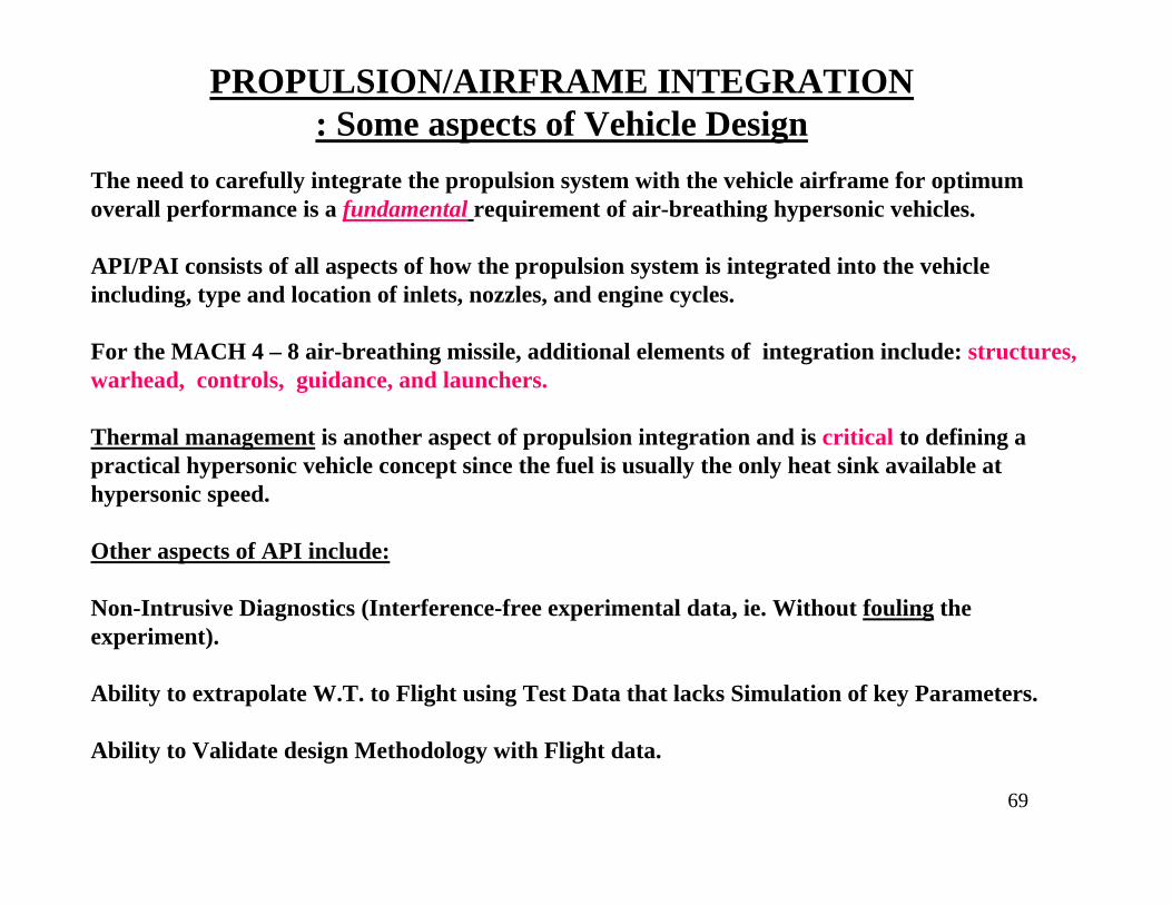
PROPULSION/AIRFRAME INTEGRATION: Some aspects of Vehicle Design
The need to carefully integrate the propulsion system with the vehicle airframe for optimum overall performance is a fundamental requirement of air-breathing hypersonic vehicles.
API/PAI consists of all aspects of how the propulsion system is integrated into the vehicle including, type and location of inlets, nozzles, and engine cycles.
For the MACH 4 – 8 air-breathing missile, additional elements of integration include: structures, warhead, controls, guidance, and launchers.
Thermal management is another aspect of propulsion integration and is critical to defining a practical hypersonic vehicle concept since the fuel is usually the only heat sink available at hypersonic speed.
Other aspects of API include:
Non-Intrusive Diagnostics (Interference-free experimental data, ie. Without fouling the experiment).
Ability to extrapolate W.T. to Flight using Test Data that lacks Simulation of key Parameters.
Ability to Validate design Methodology with Flight data.
69

70
Propulsion system improvements require advances in propulsor and core technologies
Alan EpsteinPratt & Whitney Aircraft
Core Improvements(direct impact on LTO NOx)
Propulsor improvements
Propulsion SystemsPropulsion Systems

71
Propulsor TechnologyPropulsor TechnologyUltra high bypass ratio propulsorDucted v Unducted trade, noise v efficiency
Concepts• Ducted UHB
• short inlets, laminar flow nacelles• SMA variable area nozzle• soft vane, over-the-rotor treatment
• Unducted UHB (Open Rotor)• increased rotor spacing, lower blade count
• Embedded for boundary layer ingestion• inlet flow control, distortion tolerant fan
Challenges• Open Rotor - reduced noise whilemaintaining high propulsive efficiency
• Ducted UHB - nacelle weight & drag withincreasing diameter
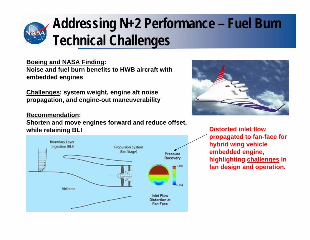
Addressing N+2 Performance – Fuel Burn Technical Challenges
Distorted inlet flow propagated to fan-face for hybrid wing vehicle embedded engine, highlighting challenges in fan design and operation.
Boeing and NASA Finding:Noise and fuel burn benefits to HWB aircraft with embedded engines
Challenges: system weight, engine aft noise propagation, and engine-out maneuverability
Recommendation:Shorten and move engines forward and reduce offset, while retaining BLI

APPROACH: COUPLED GROUND-TEST (HTF), THEORETICAL WORK, AND FLIGHT-TEST
INTEGRATION-IN- STEPS: INTERACTIONS TESTING: Build-up Methodology, 5 Configurations to be tested (combustor, combustor+isolator, combustor+isolator+inlet, combustor+isolator+inlet+nozzle , … complete engine(vehicle).
TURBO-RAM TRANSITION.
SCRAMJET SCALING: -- issue is lack of a set of scaling parameters for scram engine components and engine as a fully integrated system.
ANALYTICAL AND COMPUTATIONAL METHODS DEVELOPMENT FOR PAI
FLIGHT PERFORMANCE: use of full scale flight - test article.73

MOTIVATION ( Vehicle Scaling,..)
(II) The “technology of integration” is of unique significance in the development of hypersonic vehicles where each component affects every other component. Unfortunately, engineering practice usually leads to a subdivision by components in the design, development, and manufacturing processes; so that the “technology of integration” is not well-advanced.
Consequently, the development of a hypersonic vehicle requires an investigation and demonstration of an integrated design.
(I) There exists a critical need for an airbreathing hypersonic research vehicle that can be used to demonstrate integrated aerodynamic, propulsion, and structural technologies for hypersonic vehicle design and to develop a research database for reducing the risk involved in the development of operational hypersonic vehicles. (Ideally an air-breathing X-15, X-43 is first step)
74

75
Turbo-electric Distributed Propulsion
75
76
N+1
N+3
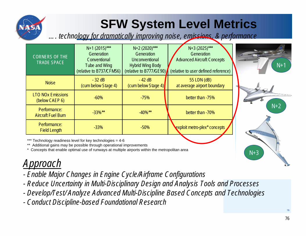
Approach- Enable Major Changes in Engine Cycle/Airframe Configurations - Reduce Uncertainty in Multi-Disciplinary Design and Analysis Tools and Processes - Develop/Test/ Analyze Advanced Multi-Discipline Based Concepts and Technologies- Conduct Discipline-based Foundational Research
SFW System Level Metrics…. technology for dramatically improving noise, emissions, & performance
N+2
CORNERS OF THETRADE SPACE
N+1 (2015)***Generation
Conventional Tube and Wing
(relative to B737/CFM56)
N+2 (2020)*** Generation
Unconventional Hybrid Wing Body
(relative to B777/GE90)
N+3 (2025)***Generation
Advanced Aircraft Concepts
(relative to user defined reference)
Noise - 32 dB (cum below Stage 4)
- 42 dB (cum below Stage 4)
55 LDN (dB) at average airport boundary
LTO NOx Emissions(below CAEP 6) -60% -75% better than -75%
Performance:Aircraft Fuel Burn -33%** -40%** better than -70%
Performance: Field Length -33% -50% exploit metro-plex* concepts
*** Technology readiness level for key technologies = 4-6** Additional gains may be possible through operational improvements* Concepts that enable optimal use of runways at multiple airports within the metropolitan area
76

77
Fuel Burn and Emission:• 2 large engine cores and multiple motor-driven fans give very high bypass ratio.• Higher propulsive efficiency via spanwise BLI and wake fill-in• High engine core inlet pressure recovery
Field Length:• Direct spanwise powered lift using low pressure fan air
Noise:• Low community noise due to low pressure fans, airframe shielding, climb & descent profile• Low core jet exhaust noise • Low cabin noise due to remote location of propulsion systems
The turboelectric approach contributes to every corner of the NASA’s SFW ‘N+3’ trade
space!
Turboelectric Distributed Propulsion / HWB advantages
77

78
Possible advantages of using a turboelectric drive system on an arbitrary “platform”
• Decoupling of the propulsive device from the power-producing device -> High performance and design flexibility
• High EBPR -> High fuel efficiency
• Speed of the power turbine shaft in the turbine engine is independent of the propulsor shaft speed. -> Electrical system as a gearbox with an arbitrary gear ratio
• Minimal engine core jet noise due to maximum energy extraction
• Symmetric thrust with an engine failure
• Asymmetric fan thrust using fast response electric motors
• Cryogenic H2 as fuel and cooling fluid for superconducting system 78

79
Turbo-electric Distributed Propulsion Vehicle (N3-X)
N2A
N3-X
CESTOL
SAX-4079
8080
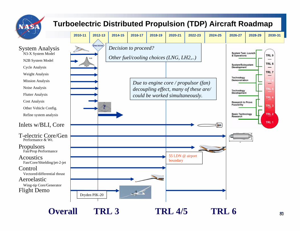
Turboelectric Distributed Propulsion (TDP) Aircraft Roadmap
System Analysis
Inlets w/BLI, Core
T-electric Core/Gen
Propulsors
Acoustics
Control
Aeroelastic
Flight Demo
TRL 6TRL 4/5TRL 3Overall
N3-X System Model
N2B System Model
Cycle Analysis
Weight Analysis
Mission Analysis
Noise Analysis
Flutter Analysis
Cost Analysis
Other Vehicle Config.
Refine system analysis
Performance & Wt.
Fan/Prop Performance
Fan/Core/Shielding/jet-2-jet
Vectored/differential thrust
Wing-tip Core/Generator
~19
4 feet
~19
4 feet
55 LDN @ airport boundary
Dryden PIK-20
Due to engine core / propulsor (fan) decoupling effect, many of these are/ could be worked simultaneously.
Decision to proceed?
Other fuel/cooling choices (LNG, LH2,..)
??
2010-11 2012-13 2014-15 2016-17 2018-19 2020-21 2022-23 2024-25 2026-27 2028-29 2030-31
DecisionDecision

Ioffe Institute Ballistic Range Tests Showing Effects of Weak IonizationVelocity = 2000 m/s
Without Pre-ionization
With Pre-ionization
81

National Aeronautics and Space Administration
www.nasa.gov 82
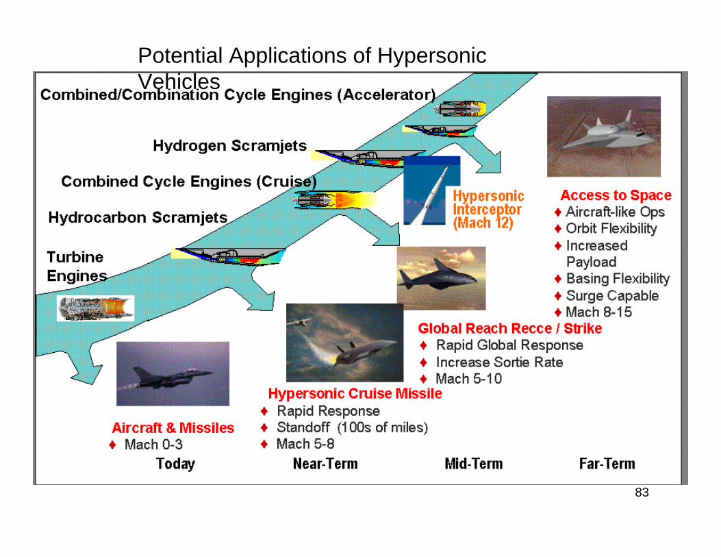
Potential Applications of Hypersonic Vehicles
83

Air-breathing Hypersonics Research Issues
CH4+3/2 CO2CH4+3/2 CO2-->CO+ 2H2O>CO+ 2H2OCO+1/2O2 CO+1/2O2 -->CO2>CO2Kf=1.2x10e10 Kb=5x10e8Kf=1.2x10e10 Kb=5x10e8SiH4 + 5O2 SiH4 + 5O2 --> SiO2 + > SiO2 + 4H2O4H2O
Engine/airframe integrationHigh efficiency inletStarting/unstartingUnsteady flows
Finite-rate chemistryFuel selection and handlingPiloting and enhancersNozzle reactionsEngine/attitude coupling
Engine selection - combined cyclesInternal flowsFuel injection and mixingMultimode operation
Leading edge physicsShock locationOff-design aerodynamicsSharp leading edge heatingAdvanced materialsBoundary layers (transition, etc.)
Aircraft/Spacecraft maneuvering and reentry
Downrange, in Mm
Alt.In km
Trajectory selectionPeriodic cruiseMulti-stagingOff-design optimizationTransonic dragLanding/takeoff
CFD: External/Internal FlowsValidation above M=8
Hypersonic Stability and Control
Structural Concepts and ActiveCooling.
Materials: long-life, high temperature,re-usable. TPS.
Airbreathing propulsion: scramjet performanceflowpath optimizationinstalled performanceengine/airframe integration
TEST FACILITIES !!!!!!!
84
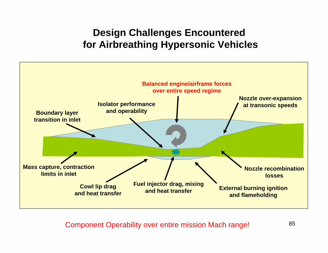
Mass capture, contractionlimits in inlet
Cowl lip dragand heat transfer
Isolator performanceand operabilityBoundary layer
transition in inlet
Balanced engine/airframe forcesover entire speed regime
Nozzle over-expansionat transonic speeds
Nozzle recombinationlosses
Fuel injector drag, mixingand heat transfer External burning ignition
and flameholding
Design Challenges Encountered for Airbreathing Hypersonic Vehicles
Component Operability over entire mission Mach range! 85

PROPULSION/ AIRFRAME/CONTROLS INTEGRATION ISSUES ADDRESSED AT NASA
Being worked in R & T base program• Ground effects at take off• Transonic drag, base drag reduction• Forebody design; flow uniformity, boundary layer transition• Nozzle design; flow chemistry, 3-D effects• Static/ dynamic stability, controls effectiveness• Off-design effects; reduced power, inlet unstart• Installed performance prediction
– test techniques, powered models– nose-to-tail analysis using CFD
• Forebody/ nozzle integrated propulsion tests86

Flow Path OptimizationValidity/ accuracy of numerical methods is key factor (especially atconditions of maximum sensitivity)
Forebody/ inlet interactions– Forebody performance (non-isothermal wall)– Forebody sensitivity (pitch, yaw, drag)– B/L state; Shock/ B-L-interaction.Internal engine flowfield– Inlet distortion– B/L entering combustor– Non-uniformity and chemistry of flow exiting combustorNozzle/ afterbody interaction– Engine exhaust stream influence on aftbody– Assessment and control of aftbody performance.
87

Installed Performance Assessment
• Maximum sensitivity/uncertainty at:– Transonic speed– Hypersonic powered flight M > 5
• Ground effects at takeoff (for canister-mounted vehicles)• Powered configuration testing
– Usually done with small subscale models
• Scaling of ground data to flight ((viscous flows, chemistry (real gas effects, etc.))– Ground-test vehicle and flight vehicle are same size and shape
88

National Aeronautics and Space Administration
www.nasa.gov 89

90

Subsonic/Supersonic Propulsion Research
Collaboration Opportunities in the NASA Collaboration Opportunities in the NASA Subsonic Fixed Wing ProjectSubsonic Fixed Wing Project
Subsonic and Supersonic Propulsion (Gas turbine research (new topics such as Weakly‐ionized Plasmas to turbine blades), Exoskeletal Engine Concept, Embedded propulsion, Distributed Propulsion, Turboelectric Propulsion…
Application of Weakly‐ionized Plasmas (plasmas in aero and space, plasma aero flow control, plasma‐assisted ignition and combustion, fuel reforming by plasma,…
91
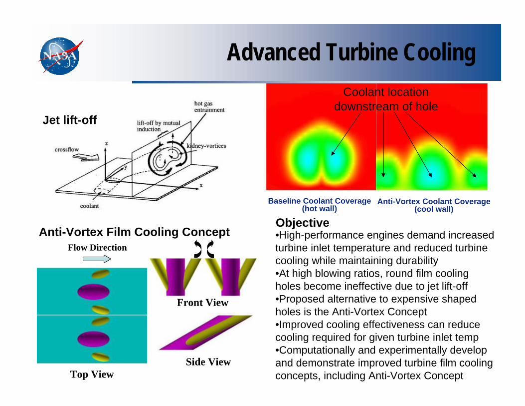
Advanced Turbine Cooling
Objective•High-performance engines demand increased turbine inlet temperature and reduced turbine cooling while maintaining durability•At high blowing ratios, round film cooling holes become ineffective due to jet lift-off•Proposed alternative to expensive shaped holes is the Anti-Vortex Concept•Improved cooling effectiveness can reduce cooling required for given turbine inlet temp•Computationally and experimentally develop and demonstrate improved turbine film cooling concepts, including Anti-Vortex Concept
Jet lift-off
Top View
Flow Direction
Front View
Side View
Anti-Vortex Film Cooling Concept
Baseline Coolant Coverage(hot wall)
Anti-Vortex Coolant Coverage(cool wall)
Coolant locationdownstream of hole

93
FAP Hypersonic: Propulsion Technology Integration: TBCC Dual Integrated Inlet Mode Transition
Test Approach (GRC 10x10 wind Tunnel)1. Inlet w/ simulated Engine backpressure2. Demonstrate mode transition control
strategies and ability to recover from inlet unstart
3. Add engines/ nozzle for integrated system test
High Mach Turbine
Dual Inlet
Facility Strut Mount
Test Approach (GRC 10x10 wind Tunnel)1. Inlet w/ simulated Engine backpressure2. Demonstrate mode transition control
strategies and ability to recover from inlet unstart
3. Add engines/ nozzle for integrated system test
High Mach Turbine
Dual Inlet
Facility Strut Mount
Test Approach (GRC 10x10 wind Tunnel)1. Inlet w/ simulated Engine backpressure2. Demonstrate mode transition control
strategies and ability to recover from inlet unstart
3. Add engines/ nozzle for integrated system test
High Mach Turbine
Dual Inlet
Facility Strut Mount
High Mach Turbine
Dual Inlet
Facility Strut Mount
Activities:Develop multi-disciplinary technology critical to enable Turbine-Based Combined-Cycle (TBCC) propulsion systems for
application to Highly Reusable, Reliable Launch Systems (HRRLS)TBCC propulsion system integration issues addressed by design and fab of proof of concept over/under TBCC propulsion system (Mach 7 design with transition from Mach 3-4) to be tested in GRC 10x10Database of TBCC dual-integrated inlet performance and operability including definition of engine inlet distortion for various bleed, ramp, cowl, and backpressure over the Mach range of 2-4.Controlled Inlet Mode Transition from Turbine to Scramjet Engine flowpathsTestbed for Integrated inlet/engine testing and mode transition controls developmentTBCC Integrated turbine engine technology/ database for start-up, shutdown, and re-lightEngine design and analysis codes (inclusive of CFD w/ bleed models, engineering-level tools, and control models)
IMPACTFirst full-scale inlet mode transition study
• engine inlet distortions quantified• enables quantification of parametrics on bleed, performance, and distortion to validate tools
First TBCC mode transition w/ actual turbine engine installed• engine and inlet operability addressed• controlled mode tranisition studie
Schedule / Milestones:2009 4th QTR: High Mach Turbine Engine SLS test w/ integrated nozzle2009 4th QTR: Inlet Model installation into GRC 10x10 facilty 2010 1st QTR: Complete parametric inlet characterization2010 3rd QTR: Complete inlet system ID tests (unsteady) for control models 2011 4th QTR: Demonstrate controlled mode transition w/ simulated engines2012 3rd QTR: Demonstrate controlled mode transition w/ turbine engine

Plum Brook Station
Location: Cleveland, OhioCivil Service FTE: o ~ (1750)On-Site Contractors: o ~ (1200)Total Area: 350 Acres
Location: Sandusky, OhioCivil Service FTE: 15On-site Contractors: 75 Total Area: 6400 Acres
Glenn – Two Campuses Working Together to Achieve NASA’s Mission
Lewis Field Main Campus
Combined current replacement value is $2 to $3 billion dollars94

National Aeronautics and Space Administration
www.nasa.gov
FY12FY10 FY13FY11FY09FY08
Hypersonic Project: TBCC Discipline Roadmap
FY12FY10 FY13FY11FY09 FY14Fiscal-Year
TBCC Design, Analysis & Dynamic models
TBCC Dyn. Sim. Model Dev. (Spiritech)
Mode Transitioning forDual Flow TBCC
TBCC Integrated Flowpath Tech.CCE Mode Transition Testing Inlet Mode Transition
w/ control
Controls Modeling, Development & Demonstration
Inlet Characterization
TBCC Component Technology
Fan Operability & Inlet Distortion Compare Distortion CFD to Data
TBCC Bleed modeling 15 x 15 bleed experiments
Bleed modelenhancement
Fully Integrated TBCC
Inlet Dynamics Test
RELEVANT MILESTONES FROM CONTROLS DISCIPLINE
Inlet Engine Mode Transition w/ control
Combined Cycle Propulsion System Design Tools& Dynamic models validated
Combined Cycle Propulsion Inlet Design Tools Evaluated
Pre-test Predictionsw/distortion)
Validated Bleed Model
Engine SLS) w/ CCE Nozzle
Assess Flowpath Integration Tools for TBCC ASSESS Design and
Dynamic Models)
Assess Mode Transition Process
Altitude direct Connect
Engine (s) test
95
96
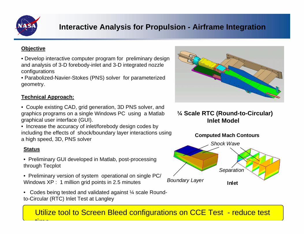
Interactive Analysis for Propulsion - Airframe Integration
¼ Scale RTC (Round-to-Circular)Inlet Model
Computed Mach Contours
InletBoundary Layer
Shock Wave
Separation
Computed Mach Contours
InletBoundary Layer
Shock Wave
Separation
Status
• Preliminary GUI developed in Matlab, post-processing through Tecplot
• Preliminary version of system operational on single PC/ Windows XP : 1 million grid points in 2.5 minutes
• Codes being tested and validated against ¼ scale Round-to-Circular (RTC) Inlet Test at Langley
Objective
• Develop interactive computer program for preliminary design and analysis of 3-D forebody-inlet and 3-D integrated nozzle configurations• Parabolized-Navier-Stokes (PNS) solver for parameterized geometry.
Technical Approach:
• Couple existing CAD, grid generation, 3D PNS solver, and graphics programs on a single Windows PC using a Matlab graphical user interface (GUI).• Increase the accuracy of inlet/forebody design codes by including the effects of shock/boundary layer interactions using a high speed, 3D, PNS solver
Utilize tool to Screen Bleed configurations on CCE Test - reduce test time

97
• Bleed modeling is critical aspect of the CFD simulation of the low-speed flowpath.
• Objective is to be able to predict bleed rates and plenum pressures.
• Bleed model should capture the spatial variation of the bleed rates over the bleed region due to pressure variations.
• Bleed model should capture the variation of the bleed rates due to interaction of the terminal shock. This is especially important for the throat bleed regions.
• The variation in the bleed rate with back-pressure is what creates the “knee” in the inlet characteristic cane curve.
• Bleed model should be capable of simulating constant-pressure and fixed-exit bleed plenums.
• CFD simulations will explore the role of bleed and the need for control of bleed during inlet mode transition.
Bleed ModelingBleed Modeling