implementation and statistical analysis of a …ee.bradley.edu/projects/proj2002/diffgps/final...
TRANSCRIPT
1
Implementation and Statistical Analysis of a Differential GPS system
Final Document
5-21-02
Project Engineers:
Jon Kerr Jim Connor
Project Advisor: Dr. In Soo Ahn
Abstract: Global Positioning System (GPS) is a satellite based navigation system. A user’s three-dimensional position can be determined worldwide by receiving signals from satellites orbiting about the earth. Availability of GPS signals to military and civilian sectors has spawned numerous ways to harness the power of precise position determination into air, land and maritime navigation. Positioning accuracy degrades when line-of-sight to the satellites is not established due to local terrain, urban canyons, tunnels, and other forms of interference. Ionospheric delays of the satellite signals also reduce the positioning accuracy of the system. To solve these problems, a reference station with a known position may be used to process the same set of satellites a mobile station sees. The reference station then broadcasts correction information to the mobile station for aiding the position fix. Such a scheme is called differential GPS (DGPS). This senior project has established a local reference station on top of Jobst Hall on the Bradley University campus, which sends error correction information to a mobile station. The mobile station uses this information to remove position errors common to both stations – reference and mobile. The accuracy of this system is down to the centimeter level. Statistical analysis of this system includes computation of circular error probability (CEP) and dilution of precision in terms of a number of available satellites. Statistical analysis can help users understand what factors cause position accuracy degradation. The overall configuration of the system, signal processing and statistical analysis will be presented and discussed. We hope that future senior projects will be able to control GPS guided autonomous vehicles more accurately by utilizing DGPS.

2
Table of Contents:
Section number and Title Page #
I. Introduction 3
II. Functional Description Figure 1 – Functional Description
3 3
III. System Block Diagram Figure 2 – Overall System Block Diagram
4 4
IV. Project Goals 5
V. Software Implementation Figure 3 – Software flow chart
5 5
VI. Equipment list 6
VII. Conclusions Figure 4 – DGPS Data Figure 5 – DGPS Scatter Plot Figure 6 – GPS Steady State Figure 7 – Dilution of Precision Figure 8 – DGPS vs GPS Table 1 – DGPS vs GPS
6 7
8
8
9
10
10
VIII. Recommendations 11
IX. Further Research 11
Appendix A: Procedure 12
Appendix B: Standards and References 14
Appendix C: Software Code 16
Appendix D: GPS Glossary 25
Appendix E: NovAtel Data Sheet 32
3
I. Introduction: The implementation of a differential GPS system was needed because normal GPS is not accurate enough for application that would like to be accomplished on Bradley University Campus. In order to accomplish DGPS, two GPS units are required, a reference station and a remote station. A reference station with a known position sends error correction data to a mobile unit wirelessly through a radio link. This DGPS system consists of two Novatel RT-20 receivers and two Freewave Radios. On the remote side, there is a laptop computer, which collects data from the GPS receiver. After the data is collected, it is then analyzed using Matlab. This system was defined, designed and implemented to fulfill the capstone project required in the Undergraduate Electrical Engineering program at Bradley University. The deliverables for the project include: • A functional description • A system block diagram • Data specifications for equipment used • A timeline for completion of project goals The system was implemented in the laboratory. The resulting system consisted of a master GPS unit capable of communicating error correction to a slave GPS unit. II. Functional Description:
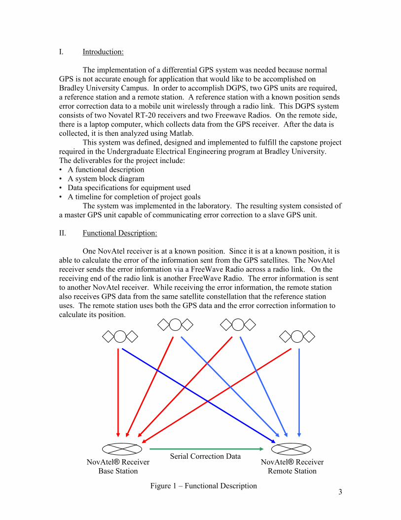
One NovAtel receiver is at a known position. Since it is at a known position, it is able to calculate the error of the information sent from the GPS satellites. The NovAtel receiver sends the error information via a FreeWave Radio across a radio link. On the receiving end of the radio link is another FreeWave Radio. The error information is sent to another NovAtel receiver. While receiving the error information, the remote station also receives GPS data from the same satellite constellation that the reference station uses. The remote station uses both the GPS data and the error correction information to calculate its position.
NovAtel® Receiver
Base Station
Serial Correction Data NovAtel® Receiver Remote Station
Figure 1 – Functional Description

4
III. System Block Diagram:
Figure 2 – Overall System Block Diagram
Commands are sent to the reference station using Windows HyperTerminal to set up differential positioning mode. Then the reference station logs differential corrections and sends them out via the wireless link. The mobile station is set up to receive the corrections transmitted from the reference station. A computer then captures the data and processes it using Matlab. Commands Used To configure reference station • fix position latitude, longitude, height • log com1 rtcm3 ontime 1 • log com1 rtcm59 ontime 1 • log com1 rtcm ontime 1 To configure mobile station • accept com2 rt20 • log com1 p20a ontime 1 • log com1 dopa ontime 1 RTCM3 is the reference station parameters. This command tells the base mobile station the reference station’s exact location, and which satellites it is using in its position calculation. RTCM59 allows the mobile station to access the carrier phase, which is how
Reference
Station
RF
modem
RF
modem
Mobile
Station
Computer
Matlab
Dat
Commands
Binary data stream

5
centimeter level accuracy is achieved. RTCM contains selected information from all of these corrections and is used as a safety in case there are errors in one of the other two corrections. The only time that the mobile station will use RTCM is when the other two contain corrupted data. On the mobile side, ACCEPT RT20 simply accepts the three RTCM commands from the reference station. LOG P20A logs the position and satellite information and the LOG DOPA logs the dilution of precision. IV. Project Goals The goals of this project are to use the equipment available to create a differential GPS system. DGPS removes the following GPS errors:
�Ionosphere 0-30 meters Mostly Removed �Troposphere 0-30 meters All Removed �Signal Noise 0-10 meters All Removed �Ephemeris Data 1-5 meters All Removed �Clock Drift 0-1.5 meters All Removed �Multipath 0-1 meters Not Removed �SA 0-70 meters All Removed One the system is functional, data will be taken and processed in Matlab to examine the overall performance. Both GPS modes will be investigated, stand alone GPS and differential GPS. Statistical analysis will be performed on the systems to determine what factors affect the accuracy and how accurate differential GPS can get. V. Software Implementation: The goal of the software is to view the collected data in the form of a scatter plot and to view the data separated by latitude, longitude, and height. The satellite switching also needs to be plotted. Also, average position calculations and CEP values are desired.
Open and read log file
Convert latitude and longitude to local coordinates (meters)
Calculate CEP
Plot graphs
Calculate and display mean values
Figure 3 – Software flow chart
6
There are three types of log files used in this project. They are POSA, P20A, and DOPA. POSA is just position information. P20A is position and satellite information. DOPA is dilution of precision information. The user is prompted to choose which log file is being used. • R = input('What type of log file is it? 1=POSA 2=P20A 3=P20A and DOPA ') Next, an input dialog box pops up and prompts the user to enter the file name of the log file being used. • file = INPUTDLG('Enter the File name','Enter GPS log file to open') Finally a text read function extracts all the desired information from the log file and puts the information in array form. • [time lat long height] = textread(file, ' %*s %f %*[^\n]', 'delimiter',',') The latitude and longitude coordinates are in decimal form in the log file. In order to interpret these values, they need to be converted in the local coordinate system, which is North, East, and Down. Using the Earths Shape and spherical coordinate conversion equations, the NED coordinates are obtained. To calculate the CEP, a radius of a circle where half of the points lie within must be found. To do this, the distance from the average position to all the point is found. This distance is compared to an incrementing radius. Starting at a 1mm radius, the program calculates how many points are inside the circle. If half are not inside, then the radius is incremented by 1mm. The program calculated how many points are inside that circle and determines if half of the points are in that circle. The program continues with this process until it finds a radius where half the points lie inside its circle. To display the mean values, the decimal longitude and latitude need to be converted to degrees, minutes, and seconds. This is done using simple calculations and the average values of the latitude, longitude, and height are displayed. See appendix C for the Matlab software listing. VI. Equipment list: 12 VDC batteries + connection wires made for GPS receiver and radios (4) Novatel RT20 Receiver (2) Freewave Wireless Modem (2) Laptop Computer (1) VII. Conclusions: At the end of the Spring 2002 Semester the system consisted of two GPS units operating together to make a DGPS system with accuracy in the centimeter level. The

7
project met the projected goals, and the desired accuracy was obtained. We were able to achieve greater position accuracy using the DGPS method.
Figure 4 – DGPS Data
This graph, shown in Figure 4, shows the number of satellites used in the position fix and the position in terms of East, North, and height. The graph shows that the GPS receiver took about 16 minutes to reach a steady state, where the position varies little, and the satellite constellation remains relatively stable.
16 min
8
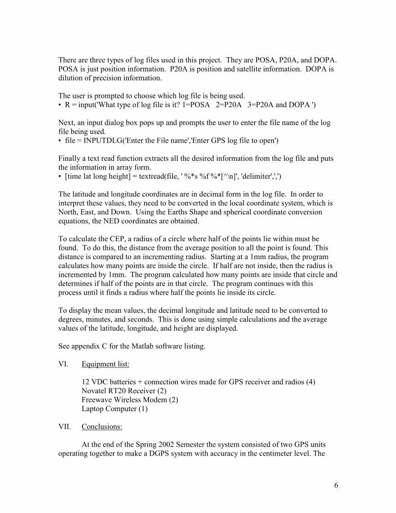
Figure 5 – DGPS Scatter Plot
Figure 5 shows the scatter plot of Figure 4. The long trailing action is due to the fact that the GPS receiver does not use the differential correction until it collects enough data. After the system uses the corrections, the position converges to a position in the centimeter level of accuracy, as seen in Figure 6.
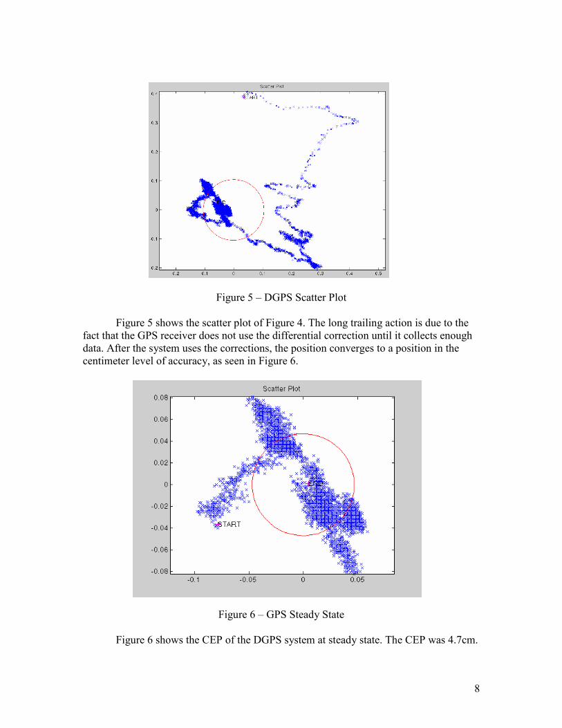
Figure 6 – GPS Steady State
Figure 6 shows the CEP of the DGPS system at steady state. The CEP was 4.7cm.
9
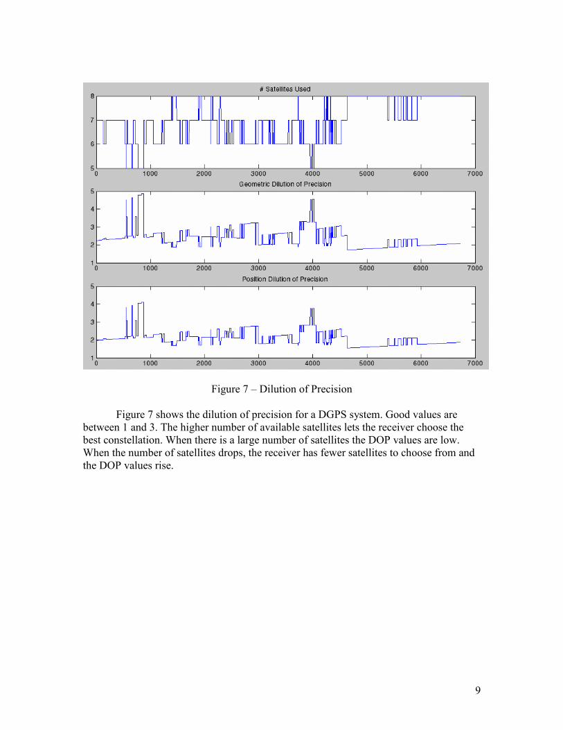
Figure 7 – Dilution of Precision
Figure 7 shows the dilution of precision for a DGPS system. Good values are between 1 and 3. The higher number of available satellites lets the receiver choose the best constellation. When there is a large number of satellites the DOP values are low. When the number of satellites drops, the receiver has fewer satellites to choose from and the DOP values rise.
10
GPS/DGPS Comparisons
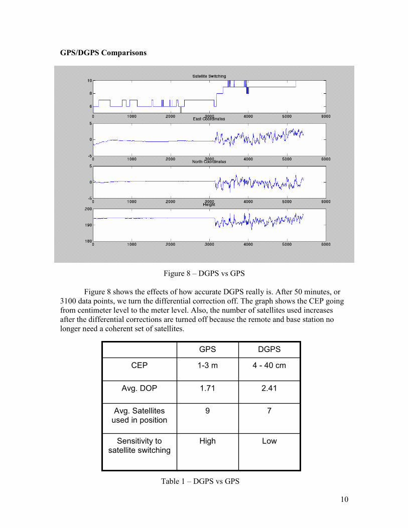
Figure 8 – DGPS vs GPS
Figure 8 shows the effects of how accurate DGPS really is. After 50 minutes, or 3100 data points, we turn the differential correction off. The graph shows the CEP going from centimeter level to the meter level. Also, the number of satellites used increases after the differential corrections are turned off because the remote and base station no longer need a coherent set of satellites.
7 9 Avg. Satellites used in position
Low High Sensitivity to satellite switching
2.41 1.71 Avg. DOP
4 - 40 cm 1-3 m CEP
DGPS GPS
Table 1 – DGPS vs GPS
11
VIII. Recommendations: Two types of antennas were used with the GPS receivers. One antenna was a NovAtel brand and worked well. The other was a Magnavox antenna and did not perform as well as the NovAtel antenna. It could take as long as ten minutes to receive any satellite information. It is suggested that another NovAtel antenna is purchased to replace the Magnavox antenna currently being used. For the project this semester, each time the reference station was set up, all the equipment had to be taken to the roof of Jobst Hall and configured. This was a time consuming process. It is suggested that a permanent reference station is built somewhere on top of Jobst Hall. The reference station should have a constant power source instead of using batteries and the station should be able to transmit corrections as needed. IX. Further Research: This year’s project specification transmitted the differential corrections at one speed, once every second. There is a spec for each type of differential correction on how fast it must be sent to the remote station. The range is usually no longer than 30 seconds. A variable update rate is desired. The NovAtel RT-20 has preliminary support of a relatively new correction standard, the RTCA standard. It is supposed to have better error detection and performance. It is expected to perform better. When the remote station is moving, the position accuracy varies. The consistency of the position should be measured. A path should be traced out with the remote station, and the different paths can be plotted on top of each other. This will show the feasibility of using the system to control a vehicle.
12
Appendix A Procedure [Procedure to operate two NovAtel RT-20 GPS receivers in a differential mode.]
SET UP BASE STATION
• Attach GPS antenna to one GPS NovAtel receiver
• Plug in 12V battery to the GPS NovAtel receiver
• Attach antenna to the radio modem
• Plug in battery for one radio modem
• Attach serial modem cable (with proper adapters) from the radio modem serial port to COM2 on the GPS receiver. The gender bender adaptor and null modem adaptor are necessary to connect the modem to the GPS receiver because of different hardware configurations
• Attach a laptop computer to COM1 on the GPS receiver via a serial cable.
• On the laptop, open up Windows HyperTerminal or some equivalent serial protocol program.
• Choose any name for the connection label
• Choose Connect using: COM1 or whatever COM port your laptop is using
• Choose Bits per Second: 9600
• You are now connected to the GPS receiver
• Type version and hit enter to verify the connection. The receiver will echo the version and model number to the screen. This is one of only about three commands that will actually echo characters to the screen. It’s helpful in determining a successful connection
Now input commands to the receiver to setup a differential base station:
• Type fix position LAT LONG HEIGHT Ex: fix position 40.699037 –89.6171221 192.345
• Type log com2 rtcm3 ontime 1
• Type log com2 rtcm59 ontime 1
• Type log com2 rtcm ontime 1
• No confirmation will appear if correct but if a wrong command is entered in a error message will appear
• Unplug the laptop from COM1
• The differential base station is now ready and sending correction data through the GPS receiver’s COM2 port
13
SET UP REMOTE STATION
• Attach GPS antenna to one GPS NovAtel receiver
• Plug in 12V battery to the GPS NovAtel receiver
• Attach antenna to the radio modem
• Plug in battery for one radio modem
• Attach serial modem cable (with proper adapters) from the radio modem serial port to COM2 on the GPS receiver. The gender bender adaptor and null modem adaptor are necessary to connect the modem to the GPS receiver because of different hardware configurations
• Attach a laptop computer to COM1 on the GPS receiver via a serial cable.
• On the laptop, open up Windows HyperTerminal or some equivalent serial protocol program.
• Choose any name for the connection label
• Choose Connect using: COM1 or whatever COM port your laptop is using
• Choose Bits per Second: 9600
• You are now connected to the GPS receiver
• Type version and hit enter to verify the connection. The receiver will echo the version and model number to the screen. This is one of only about three commands that will actually echo characters to the screen. It’s helpful in determining a successful connection
Now input commands to the receiver to setup a differential remote station:
• Type accept com2 rt20
• Type log com1 p20a ontime 1. (In place of p20a, you can put any type of log file you want to record. See manual for types.)
• The HyperTerminal screen should start to output the log data
Now capture the log file data to a text file on your computer:
• Go to Transfer in the HyperTerminal
• Go to Capture Text…
• Choose the file you want to output the log to and hit start
• Remote station is now ready, receiving corrections, and outputting the log file
14
Appendix B Standards/References RTCM STANDARDS REFERENCE
For detailed specifications of RTCM, refer to RTCM SC104 Version 2.1 of "RTCM Recommended Standards For Differential NAVSTAR GPS Service", January 3, 1994 Radio Technical Commission for Maritime Services 655 15th Street NW, Suite 300 Washington, D.C. 20005 U.S.A. Telephone: 202-639-4006 Fax: 202-347-8540 website: http://www.navcen.uscg.mil/dgps/dgeninfo
RTCA STANDARDS REFERENCE
For copies of the Minimum Aviation System Performance Standards DGNSS Instrument Approach System: Special Category-I (SCAT-I), contact: RTCA, Incorporated 1140 Connecticut Avenue N.W., Suite 1020 Washington, D.C. 20036-4001 U.S.A. Telephone: 202-833-9339 Fax: 202-833-9434 website: http://www.rtca.org
GPS SPS SIGNAL SPECIFICATION REFERENCE
For copies of the Interface Control Document (ICD)-GPS-200, contact: ARINC Research Corporation 2551 Riva Road Annapolis, MD 21401-7465 Telephone: 410-266-4000 Fax: 410-266-4049 website: http://www.arinc.com
NMEA REFERENCE
National Marine Electronics Association, NMEA 0183 Standard for Interfacing Marine Electronic Devices, Version 2.00, January 1, 1992 NMEA Executive Director P.O. Box 50040 Mobile, Alabama 36605 U.S.A. website: http://www.nmea.org
GEODETIC SURVEY OF CANADA
Geodetic Survey of Canada 615 Boothe Street Ottawa, Ontario K1A 0E9 Telephone: (613) 995-4410 Fax: (613)995-3215 website: http://www.geod.emr.ca

15
U.S. NATIONAL GEODETIC SURVEY
NGS Information Services 1315 East-West Highway Station 9244 Silver Springs, MD 20910-3282 Telephone: (301)713-2692 Fax: (301)713-4172 website: http://www.ngs.noaa.gov Website addresses may be subject to change however they are accurate at the time of publication.

16
Appendix C Software Code % GPSmain.m % Author: Jim Connor ([email protected]) % 03/05/2002 % Program reads a log file produced by the NovAtel RT20 % receiver and imports data into the Matlab workspace % The program then graphs the scatter plot in NED coordinates % and calculates the CEP. Also displays the mean coordinates R = input('What type of log file is it? 1=POSA 2=P20A 3=P20A and DOPA '); % Input dialog box to enter the GPS log file to open % Format is filename.txt Ex: GPSlog2.txt file = INPUTDLG('Enter the File name','Enter GPS log file to open'); file=char(file); % the file must be a character array to work % Textread opens the file, pulls out information, and stores it in % the four arrays. See 'help textread' for programming format if R==1 [time lat long height] = textread(file, ' %*s %*d %f %f %f %f %*[^\n]', 'delimiter',','); elseif R==2 [time sat lat long height rt20stat stat] = textread(file, ' %*s %*d %f %*f %d %f %f %f %*f %*f %*f %*f %*f %*f %d %d %*[^\n]', 'delimiter',','); else GPSDOP; end GPSConvert %Changes Longitude and Latitude coordinates to NED coordinates GPSCEP %Calls file that calculates the CEP GPSPlot %Plots the scatter plot GPSCalculate %Displays CEP and mean LAT, LONG and Height
17
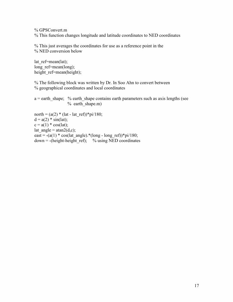
% GPSConvert.m % This function changes longitude and latitude coordinates to NED coordinates % This just averages the coordinates for use as a reference point in the % NED conversion below lat_ref=mean(lat); long_ref=mean(long); height_ref=mean(height); % The following block was written by Dr. In Soo Ahn to convert between % geographical coordinates and local coordinates a = earth_shape; % earth_shape contains earth parameters such as axis lengths (see % earth_shape.m) north = (a(2) * (lat - lat_ref))*pi/180; d = a(2) * sin(lat); c = a(1) * cos(lat); lat_angle = atan2(d,c); east = -(a(1) * cos(lat_angle).*(long - long_ref))*pi/180; down = -(height-height_ref); % using NED coordinates
18
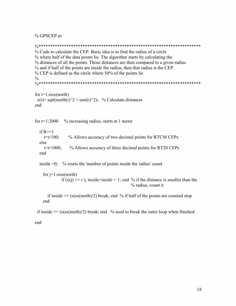
% GPSCEP.m %********************************************************************** % Code to calculate the CEP. Basic idea is to find the radius of a circle % where half of the data points lie. The algorithm starts by calculating the % distances of all the points. Those distances are then compared to a given radius % and if half of the points are inside the radius, then that radius is the CEP. % CEP is defined as the circle where 50% of the points lie % %********************************************************************** for i=1:size(north) x(i)= sqrt(north(i)^2 + east(i)^2); % Calculate distances end for r=1:2000 % increasing radius, starts at 1 meter if R==1 r=r/100; % Allows accuracy of two decimal points for RTCM CEPs else r=r/1000; % Allows accuracy of three decimal points for RT20 CEPs end inside =0; % resets the 'number of points inside the radius' count for j=1:size(north)
if (x(j) <= r ), inside=inside + 1; end % if the distance is smaller than the % radius, count it
if inside >= (size(north)/2) break; end % if half of the points are counted stop end if inside >= (size(north)/2) break; end % used to break the outer loop when finished end
19
% GPSPlot.m % The scatter plot is then plotted and the graph is held so the CEP circle can be drawn plot(east,north,'x'),title('Scatter Plot') axis equal hold; % Plots Start and End points plot(east(1),north(1),'m*') text(east(1),north(1),'START') plot(east(size(east)),north(size(north)),'m*') text(east(length(time)),north(length(time)),'END') % This code plots a red circle of radius r, previosly calculated, on top of the scatter plot % There has to be a more efficient way to draw transparent circles in MATLAB! Let me know. n = 50; th = linspace(0,2*pi,n); rr = r * ones(1,n); [xx,yy] = pol2cart(th,rr); plot(xx,yy,'r') if R==1 figure(2),... subplot(311),plot(east),title('East Coordinates'),... subplot(312),plot(north),title('North Coordinates'),... subplot(313),plot(height),title('Height') elseif R==2 figure(2),... subplot(411),plot(sat),title('Satellite Switching'),... subplot(412),plot(east),title('East Coordinates'),... subplot(413),plot(north),title('North Coordinates'),... subplot(414),plot(height),title('Height'),... figure(3),... subplot(211),plot(rt20stat),title('Correction Status - 0=best 8=worst'),... subplot(212),plot(stat),title('Differential Corrections - 2=DGPS 1=Normal') else figure(2),... subplot(411),plot(sat),title('Satellite Switching'),... subplot(412),plot(east),title('East Coordinates'),... subplot(413),plot(north),title('North Coordinates'),...
20
subplot(414),plot(height),title('Height'),... figure(3),... subplot(211),plot(rt20stat),title('Correction Status - 0=best 8=worst'),... subplot(212),plot(stat),title('Differential Corrections - 2=DGPS 1=Normal') figure(4) subplot(311),plot(sats),title('# Satellites Used') subplot(312),plot(gdop),title('Geometric Dilution of Precision') subplot(313),plot(pdop),title('Position Dilution of Precision') figure(5) subplot(311),plot(htdop),title('Horizontal Position and Time Dilution of Precision') subplot(312),plot(hdop),title('Horizontal Dilution of Precision') subplot(313),plot(tdop),title('Time Dilution of Precision') end
21
% GPSCalculate.m % The rest of the code is processing for display in the MATLAB command window % The data I chose to display is CEP and mean LAT, LONG and Height CEP=sprintf(' %f %c',r,'m'); CEP disp('The mean Latitude, Longitude and Height are:') if(lat_ref>0) dirLat='N';else dirLat='S';end % Chose correct direction lat_ref=abs(lat_ref); deg=floor(lat_ref); min=(lat_ref-deg)*60; % Calculate DD MM SS from the decimal value sec=(min -floor(min))*60; Lat=sprintf(' %d %d %f %c',deg,floor(min),sec,dirLat); % Display Latitude Lat if(long_ref>0) dirLong='E';else dirLong='W';end % Chose correct direction long_ref=abs(long_ref); deg=floor(long_ref); min=(long_ref-deg)*60; % Calculate DD MM SS from the decimal value sec=(min -floor(min))*60; Long=sprintf(' %d %d %f %c',deg,floor(min),sec,dirLong); % Display Longitude Long Height=sprintf(' %f %c',height_ref,'m'); % Display height above sea level Height
22
% DOP.m % Dilution of Precision % Author: Jon Kerr and Jim Connor % 04/16/2002 % This Program reads a log file produced by the NovAtel RT20 % receiver and imports data into the matlab workspace % The log file must contain the P20A log and the DOPA log % This function seperates the two formats into temp files so the % textread function can extract the data in the workspace FID=fopen(file,'r'); % Opens file FID2=fopen('temp1.txt','w'); while feof(FID)==0, line=fgetl(FID); length1=max(size(line)); if length1>30 if line(2)=='P' if line(3)=='2' if line(4)=='0' fprintf(FID2,'%s\n',line); end end end end end fclose(FID); fclose(FID2); FID=fopen(file,'r'); FID2=fopen('temp2.txt','w'); while feof(FID)==0, line=fgetl(FID); length1=max(size(line)); if length1>30 if line(2)=='D' if line(3)=='O' if line(4)=='P' fprintf(FID2,'%s\n',line); end
23
end end end end fclose(FID); fclose(FID2); [time sat lat long height rt20stat stat] = textread('temp1.txt', ' %*s %*d %f %*f %d %f %f %f %*f %*f %*f %*f %*f %*f %d %d %*[^\n]', 'delimiter',','); [gdop pdop htdop hdop tdop sats] = textread('temp2.txt', ' %*s %*d %*f %f %f %f %f %f %f %*[^\n]', 'delimiter',',');
24
% Earth_shape.m % used for coordinate conversion function y = earth_shape() % Contains earth parameters [major-axis, minor-axis, ellipticity, % eccentricity, sidereal rate] Re = 6378137.0; % semi-major axis (equatorial) radius in meters Rp = 6356752.3142; % semi-minor axis (polar) radius in meters ellipticity = (Re-Rp)/Re; % ellipticity eccentricity = sqrt(ellipticity*(2-ellipticity)); Omega = 7.292115167e-5; y = [Re, Rp, ellipticity, eccentricity, Omega];
25
Appendix D GPS Glossary ASCII A 7-bit wide serial code describing numbers, upper and lower case characters, special and non-printing characters. Typically used for textual data. Acquisition The process of locking onto a satellite’s C/A code and P code. A receiver acquires all available satellites when it is first powered up, then acquires additional satellites as they become available and continues tracking them until they become unavailable. Address Field For sentences in the NMEA standard, the fixed length field following the beginning sentence delimiter "$" (HEX 24). For NMEA approved sentences, composed of a two character talker identifier and a three character sentence formatter. For proprietary sentences, composed of the character "P" (HEX 50) followed by a three character manufacturer identification code. Almanac A set of orbit parameters that allows calculation of approximate GPS satellite positions and velocities. The almanac is used by a GPS receiver to determine satellite visibility and as an aid during acquisition of GPS satellite signals. Almanac Data A set of data which is downloaded from each satellite over the course of 12.5 minutes. It contains orbital parameter approximations for all satellites, GPS to universal standard time (UTC) conversion parameters, and single frequency ionospheric model parameters. Anti-Spoofing Denial of the P-code by the Control Segment is called Anti-Spoofing. It is normally replaced by encrypted Y-code, [see P-Code and Y-Code] Attenuation Reduction of signal strength Azimuth The horizontal direction of a celestial point from a terrestrial point, expressed as the angular distance from 000° (reference) clockwise through 360°. The reference point is generally True North, but may be Magnetic North, or Relative (ship's head). Bearing The horizontal direction of one terrestrial point from another terrestrial point, expressed as the angular distance from a reference direction, usually measured from 000° at the reference direction clockwise through 360°. The reference point may be True North, Magnetic North, or Relative (ship's head). Carrier The steady transmitted RF signal whose amplitude, frequency, or phase may be modulated to carry information. Carrier Phase The number of integer carrier phase cycles between the user and the Ambiguity satellite at the start of tracking. (Sometimes ambiguity for short) Carrier Phase These are “accumulated doppler range” (ADR) measurements. They contain Measurements the instantaneous phase of the signal (modulo 1 cycle) plus some arbitrary number of integer cycles. Once the receiver is tracking the satellite, the integer number of cycles correctly accumulates the change in range seen by the receiver. When a “lock break” occurs, this accumulated value can jump an arbitrary integer number of cycles (this is called a cycle slip). Checksum By NMEA standard, a validity check performed on the data contained in the sentences, calculated by the talker, appended to the message, then recalculated by the listener for comparison to determine if the message was received correctly. Required for some sentences, optional for all others. Circular Error Circular error probable; the radius of a circle such that 50% of a set of events Probable (CEP) occur inside the boundary. Coarse Acquisition A pseudorandom string of bits that is used primarily by commercial GPS (C/A) Code receivers to determine the range to the transmitting GPS satellite. The 1023
26
chip C/A code repeats every 1 ms giving a code chip length of 300 m which, is very easy to lock onto. Communication A method established for message transfer between a talker and a listener Protocol which includes the message format and the sequence in which the messages are to be transferred. Also includes the signaling requirements such as bit rate, stop bits, parity, and bits per character. Control Segment The Master Control Station and the globally dispersed Reference Stations used to manage the GPS satellites, determine their precise orbital parameters, and synchronize their clocks. Coordinated This time system uses the second-defined true angular rotation of the Earth Universal Time measured as if the Earth rotated about its Conventional Terrestrial Pole. (UTC) However, UTC is adjusted only in increments of one second. The time zone of UTC is that of Greenwich Mean Time (GMT). Course The horizontal direction in which a vessel is to be steered or is being steered; the direction of travel through the air or water. Expressed as angular distance from reference North (either true, magnetic, compass, or grid), usually 000° (north), clockwise through 360°. Strictly, the term applies to direction through the air or water, not the direction intended to be made good over the ground [see Track]. Differs from heading. Course Made Good The single resultant direction from a given point of departure to a subsequent (CMG) position; the direction of the net movement from one point to the other. This often varies from the track caused by inaccuracies in steering, currents, cross-winds, etc. This term is often considered to be synonymous with Track Made Good, however, Course Made Good is the more correct term. Course Over The actual path of a vessel with respect to the Earth (a misnomer in that Ground (COG) courses are directions steered or intended to be steered through the water with respect to a reference meridian); this will not be a straight line if the vessel's heading yaws back and forth across the course. Cross Track Error The distance from the vessel’s present position to the closest point on a great (XTE) Circle line connecting the current waypoint coordinates. If a track offset has been specified in the GPSCard SETNAV command, the cross track error will be relative to the offset track great circle line. Cycle Slip When the carrier phase measurement jumps by an arbitrary number of integer cycles. It is generally caused by a break in the signal tracking due to shading or some similar occurrence. Dead Reckoning The process of determining a vessel’s approximate position by applying (DR) from its last known position a vector or a series of consecutive vectors representing the run that has since been made, using only the courses being steered, and the distance run as determined by log, engine rpm, or calculations from speed measurements. Destination The immediate geographic point of interest to which a vessel is navigating. It may be the next waypoint along a route of waypoints or the final destination of a voyage. Differential GPS A technique to improve GPS accuracy that uses pseudorange errors at a (DGPS) known location to improve the measurements made by other GPS receivers within the same general geographic area. Dilution of A numerical value expressing the confidence factor of the position solution Precision (DOP) based on current satellite geometry. The lower the value, the greater the confidence in the solution. DOP can be expressed in the following forms. GDOP - uncertainty of all parameters (latitude, longitude, height, clock offset) PDOP - uncertainty of 3D parameters (latitude, longitude, height) HTDOP - uncertainty of 2D and time parameters (latitude, longitude, time) HDOP - uncertainty of 2D parameters (latitude, longitude) VDOP - uncertainty of height parameter TDOP - uncertainty of clock offset parameter Doppler The change in frequency of sound, light or other wave caused by movement
27
of its source relative to the observer. Doppler Aiding A signal processing strategy, which uses a measured Doppler shift to help a receiver smoothly track the GPS signal, to allow more precise velocity and position measurement. Double-Difference A mathematical technique comparing observations by differencing between receiver channels and then between the reference and rover receivers. Double-Difference Carrier phase ambiguities which are differenced between receiver channels Carrier Phase and between the reference and rover receivers. They are estimated when Ambiguity a double-difference mechanism is used for carrier phase positioning. (Sometimes double-difference ambiguity or ambiguity, for short) Earth-Centred- This is a coordinate-ordinate system which has the X-coordinate in the Earth-Fixed (ECEF) earth's equatorial plane pointing to the Greenwich prime meridian, the Z-axis pointing to the north pole, and the Y-axis in the equatorial plane 90° from the X-axis with an orientation which forms a right-handed XYZ system. Elevation The angle from the horizon to the observed position of a satellite. Ellipsoid A smooth mathematical surface which represents the earth’s shape and very closely approximates the geoid. It is used as a reference surface for geodetic surveys, refer to the MATCHEDPOS log in user manual Volume 2, Command and Log Reference.
Ellipsoidal Height Height above a defined ellipsoid approximating the surface of the earth. Ephemeris A set of satellite orbit parameters that are used by a GPS receiver to calculate precise GPS satellite positions and velocities. The ephemeris is used in the determination of the navigation solution and is updated periodically by the satellite to maintain the accuracy of GPS receivers. Ephemeris Data The data downlinked by a GPS satellite describing its own orbital position with respect to time. Epoch Strictly a specific point in time. Typically when an observation is made. Field A character or string of characters immediately preceded by a field delimiter. Fixed Ambiguity Carrier phase ambiguity estimates which are set to a given number and held Estimates constant. Usually they are set to integers or values derived from linear combinations of integers. Fixed Discrete Carrier phase ambiguities which are set to values which are members of a Ambiguity predetermined set of discrete possibilities, and then held constant.
Estimates
Fixed Field A field in which the number of characters is fixed. For data fields, such fields are shown in the sentence definitions with no decimal point. Other fields which fall into this category are the address field and the checksum field (if present). Fixed Integer Carrier phase ambiguities, which are set to integer values and then held Ambiguity constant.
Estimates
Flash ROM Programmable read-only memory. Floating Ambiguity Ambiguity estimates which are not held to a constant value, but are allowed Estimates to gradually converge to the correct solution. Geometric Dilution [See DOP]
of Precision (GDOP)
Geoid The shape of the earth if it were considered as a sea level surface extended continuously through the continents. The geoid is an equipotential surface coincident with mean sea level to which at every point the plumb line (direction in which gravity acts) is perpendicular. The geoid, affected by local gravity disturbances, has an irregular shape. Geodetic Datum The reference ellipsoid surface that defines the coordinate system. Geostationary A satellite orbit along the equator that results in a constant fixed position over a particular reference point on the earth’s surface. (GPS satellites are not geostationary.)
28
Global Positioning Full name is NAVSTAR Global Positioning System. A space-based radio System (GPS) Positioning system which provides suitably equipped users with accurate position, velocity and time data. GPS provides this data free of direct user charge worldwide, continuously, and under all weather conditions. The GPS constellation consists of 24 orbiting satellites, four equally spaced around each of six different orbital planes. The system is being developed by the Department of Defence under U.S. Air Force management. Great Circle The shortest distance between any two points along the surface of a sphere or ellipsoid, and therefore the shortest navigation distance between any two points on the Earth. Also called Geodesic Line. Handshaking Predetermined hardware or software activity designed to establish or maintain two machines or programs in synchronization. Handshaking concerns the exchange of messages or packets of data between two systems with limited buffers. Hardware handshaking uses voltage levels or pulses in wires to carry the handshaking signals. Software handshaking uses data units (e.g. ASCII characters) carried by some underlying communication medium. Horizontal Dilution [See DOP]
of Precision (HDOP)
Horizontal and Time [See DOP]
Dilution of Precision
(HTDOP)
Heading The direction in which a vessel points or heads at any instant, expressed in degrees 000° clockwise through 360° and may be referenced to True North, Magnetic North, or Grid North. The heading of a vessel is also called the ship's head. Heading is a constantly changing value as the vessel oscillates or yaws across the course due to the effects of the air or sea, cross currents, and steering errors. Integer Ambiguity Carrier phase ambiguity estimates which are only allowed to take on integer Estimates values. Iono-Free Carrier A linear combination of L1 and L2 carrier phase measurements which Phase Observation provides an estimate of the carrier phase observation on one frequency with the effects of the ionosphere removed. It provides a different ambiguity value (non-integer) than a simple measurement on that frequency. Kinematic The user’s GPS antenna is moving. In GPS, this term is typically used with precise carrier phase positioning, and the term dynamic is used with pseudorange positioning. L1 Frequency The 1575.42 MHz GPS carrier frequency which contains the course acquisition (C/A) code, as well as encrypted P-code, and navigation messages used by commercial GPS receivers. L2 Frequency The 1227.60 MHz. secondary GPS carrier frequency, containing only encrypted P-code, used primarily to calculate signal delays caused by the ionosphere. Lane A particular discrete ambiguity value on one carrier phase range measurement or double difference carrier phase observation. The type of measurement is not specified (L1, L2, L1-L2, iono-free) Local Observation An observation set, as described below, taken by the receiver on which the Set software is operating as opposed to an observation taken at another receiver (the reference station) and transmitted through a radio link. Local Tangent A coordinate system based on a plane tangent to the ellipsoid’s surface at the Plane user’s location. The three coordinates are east, north and up. Latitude, longitude and height positions operate in this coordinate system. Low-latency A position solution which is based on a prediction. A model (based on Solution previous reference station observations) is used to estimate what the observations will be at a given time epoch. These estimated reference station observations are combined with actual measurements taken at the remote station to provide a position solution.
29
Magnetic Bearing Bearing relative to magnetic north; compass bearing corrected for deviation. Magnetic Heading Heading relative to magnetic north. Magnetic Variation The angle between the magnetic and geographic meridians at any place, expressed in degrees and minutes east or west to indicate the direction of magnetic north from true north. Mask Angle The minimum GPS satellite elevation angle permitted by a particular receiver design. Satellites below this angle will not be used in position solution. Matched Observations from both the reference station and the local receiver Observation which have been matched by time epoch, contain the same satellites, and are Set Pair corrected for any known offsets. Measurement The square of the standard deviation of a measurement quantity. The Error Variance standard deviation is representative of the error typically expected in a measured value of that quantity. Measurement The point in time at which a GPSCard takes a measurement.
Time Epoch
Multipath Errors GPS positioning errors caused by the interaction of the GPS satellite signal and its reflections. Non-Volatile A type of memory device that retains data in the absence of a power supply.
Memory
Null Field By NMEA standard, indicates that data is not available for the field. Indicated by two ASCII commas, i.e., ",," (HEX 2C2C), or, for the last data field in a sentence, one comma followed by either the checksum delimiter "*" (HEX 2A) or the sentence delimiters <CR><LF> (HEX 0D0A). [Note: the ASCII Null character (HEX 00) is not to be used for null fields.] Obscuration Term used to describe periods of time when a GPS receiver’s line-of-sight to GPS satellites is blocked by natural or man-made objects. Observation Any measurement. The two observations used in NovAtel’s RTK algorithms are the pseudorange measurement and the carrier phase measurement. Observation Set A set of GPSCard measurements taken at a given time which includes one time for all measurements, and the following for each satellite tracked: PRN number, pseudorange or carrier phase or both, lock time count, signal strength, and tracking status. Either L1 only or L1 and L2 measurements are included in the set. The observation set is assumed to contain information indicating how many satellites it contains and which ones have L1-only and which ones have L1/L2 pairs. Origin Waypoint The starting point of the present navigation leg, expressed in latitude and longitude. Parallel Receiver A receiver that monitors four or more satellites simultaneously with independent channels. Parity The even or odd quality of the number of ones or zeroes in a binary code. Parity is often used to determine the integrity of data especially after transmission. Perigee The point in a body’s orbit at which it is nearest the earth. P-Code Precise code or protected code. A pseudorandom string of bits that is used by GPS receivers to determine the range to the transmitting GPS satellite. Pcode is replaced by an encrypted Y-code when Anti-Spoofing is active. Ycode is intended to be available only to authorized (primarily military) users. [See Anti-Spoofing, C/A Code and Y-Code] PDOP Position Dilution of Precision [See DOP] Precise Positioning The GPS positioning, velocity, and time service which is available on a Service (PPS) continuous, worldwide basis to users authorized by the U.S. Department of Defence (typically using P-Code). PRN Number A number assigned by the GPS system designers to a given set of pseudorandom codes. Typically, a particular satellite will keep its PRN (and hence its code assignment) indefinitely, or at least for a long period of time.
30
It is commonly used as a way to label a particular satellite. Pseudolite An Earth-based transmitter designed to mimic a satellite. May be used to transmit differential corrections. Pseudorange The calculated range from the GPS receiver to the satellite determined by taking the difference between the measured satellite transmit time and the receiver time of measurement, and multiplying by the speed of light. Contains several sources of error. Pseudorange Measurements made using one of the pseudorandom codes on the GPS Measurements signals. They provide an unambiguous measure of the range to the satellite including the effect of the satellite and user clock biases. Receiver Channels A GPS receiver specification which indicates the number of independent hardware signal processing channels included in the receiver design. Reference Satellite In a double difference implementation, measurements are differenced between different satellites on one receiver in order to cancel the correlated errors. Usually one satellite is chosen as the “reference”, and all others are differenced with it. Reference Station The GPS receiver which is acting as the stationary reference. It has a known position and transmits messages for the rover receiver to use to calculate its position. Relative Bearing Bearing relative to heading or to the vessel. Remote/ Rover The GPS receiver which does not know its position and needs to receive Receiver measurements from a reference station to calculate differential GPS positions. (The terms remote and rover are interchangeable.) Residual In the context of measurement, the residual is the misclosure between the calculated measurements, using the position solution and actual measurements. Root Mean Square A probability level of 68%.
(RMS)
Route A planned course of travel, usually composed of more than one navigation leg. RT-20 NovAtel’s Double Differencing Technology for real-time kinematic (RTK) carrier phase floating ambiguity resolution. Radio Technical An organization which developed and defined a message format for Commission for differential positioning. See Appendix H on Page 137 for further Aeronautics information.
(RTCA)
Radio Technical An organization which developed and defined the SC-104 message format Commission for for differential positioning. See Appendix H on Page 137 for further Maritime Services information.
(RTCM)
Real-Time A type of differential positioning based on observations of carrier phase. In Kinematic (RTK) this document it is also used with reference to RT-2 and RT-20. Selected Waypoint The waypoint currently selected to be the point toward which the vessel is travelling. Also called "to" waypoint, destination or destination waypoint. Selective The method used by the United States Department of Defence to control Availability (SA) access to the full accuracy achievable by civilian GPS equipment (generally by introducing timing and ephemeris errors). Sequential Receiver A GPS receiver in which the number of satellite signals to be tracked exceeds the number of available hardware channels. Sequential receivers periodically reassign hardware channels to particular satellite signals in a predetermined sequence. Spherical Error The radius of a sphere, centred at the user’s true location, that contains 50 Probable (SEP) percent of the individual three-dimensional position measurements made using a particular navigation system. Spheroid Sometimes known as ellipsoid; a perfect mathematical figure which very closely approximates the geoid. Used as a surface of reference for geodetic
31
surveys. Standard A positioning service made available by the United States Department of Positioning Defence which is available to all GPS civilian users on a continuous, Service (SPS) worldwide basis (typically using C/A Code). Space Vehicle ID Sometimes used as SVID. A unique number assigned to each satellite for (SV) identification purposes. The ‘space vehicle’ is a GPS satellite. TDOP Time Dilution of Precision [See DOP] Three-Dimensional The number of hours-per-day when four or more satellites are available with Coverage acceptable positioning geometry. Four visible satellites are required to determine location and altitude. Three-Dimensional Navigation mode in which altitude and horizontal position are determined (3D) Navigation from satellite range measurements. Time-To-First-Fix The actual time required by a GPS receiver to achieve a position solution. (TTFF) This specification will vary with the operating state of the receiver, the length of time since the last position fix, the location of the last fix, and the specific receiver design. Track A planned or intended horizontal path of travel with respect to the Earth rather than the air or water. The track is expressed in degrees from 000° clockwise through 360° (true, magnetic, or grid). Track Made Good The single resultant direction from a point of departure to a point of arrival or subsequent position at any given time; may be considered synonymous with Course Made Good. True Bearing Bearing relative to true north; compass bearing corrected for compass error. True Heading Heading relative to true north. Two-Dimensional The number of hours-per-day with three or more satellites visible. Three Coverage visible satellites can be used to determine location if the GPS receiver is designed to accept an external altitude input. Two-Dimensional Navigation mode in which a fixed value of altitude is used for one or more (2D) Navigation position calculations while horizontal (2D) position can vary freely based on satellite range measurements. Undulation The distance of the geoid above (positive) or below (negative) the mathematical reference ellipsoid (spheroid). Also known as geoidal separation, geoidal undulation, geoidal height. Update Rate The GPS receiver specification which indicates the solution rate provided by the receiver when operating normally. UTC [See Coordinated Universal Time] VDOP Vertical Dilution of Precision [See DOP] Variable Field By NMEA standards, a data field which may or may not contain a decimal point and which may vary in precision following the decimal point depending on the requirements and the accuracy of the measuring device. World Geodetic An ellipsoid designed to fit the shape of the entire Earth as well as possible System 1984 with a single ellipsoid. It is often used as a reference on a worldwide basis, (WGS84) while other ellipsoids are used locally to provide a better fit to the Earth in a local region. GPS uses the centre of the WGS-84 ellipsoid as the centre of the GPS ECEF reference frame. Waypoint A reference point on a track. Wide Lane A particular integer ambiguity value on one carrier phase range measurement or double difference carrier phase observation when the difference of the L1 and L2 measurements is used. It is a carrier phase
observable formed by subtracting L2 from L1 carrier phase data: Φ’ = Φ1 -
Φ2. The corresponding wavelength is 86.2 cm Y-Code An encrypted form of P-Code. Satellites transmit Y-Code in replace of PCode when Anti-Spoofing is in effect. [See P-Code and Anti-Spoofing]

32
Appendix E NovAtel RT-20 Data Sheet