installation manual for aerocet cargo …aerocet.com/wp-content/uploads/2017/06/a-10014.pdf265...
TRANSCRIPT

ISSUE DATE:
PO Box 2119 PAGE 265 Shannon Lane 1 of 14
6/07/1994 INCORPORATED Priest River ID 83856 FILE NO. REVISION DATE: TITLE: 206 Cargo Pod Installation Manual
A-10014
3/10/2009 REVISION: 2
INSTALLATION MANUAL
FOR
AEROCET CARGO PACK
ON CESSNA 206 SERIES AIRPLANES
This Installation Manual is a necessary part of an FAA Approved data package for STC #SA00096SE, providing requirements for the acceptable installation of the Aerocet 206 Cargo Pack.

ISSUE DATE:
PO Box 2119 PAGE 265 Shannon Lane 2 of 14
6/07/1994 INCORPORATED Priest River ID 83856 FILE NO. REVISION DATE: TITLE: 206 Cargo Pod Installation Manual
A-10014
3/10/2009 REVISION: 2
LOG OF REVISIONS PAGE
REV.
PAGES AFFECTED
DESCRIPTION
FAA APPROVED
DATE
I/R ALL Initial Release
1 ALL Added Cover Page 4/20/2006 Style change to Title Block, updated Company address
Added Section “G” Added Figure “6” Updated Parts Listing Updated Figures 1-5 with current
hardware and specific model call-outs with regard to Models 206H and T206H
2 ALL Changed Rivnut part number, NAS1329S3K130, was NAS1329S3K140, page 3, PART LISTING, and Page 11, FIGURE 3, illustration
3/10/2009

ISSUE DATE:
PO Box 2119 PAGE 265 Shannon Lane 3 of 14
6/07/1994 INCORPORATED Priest River ID 83856 FILE NO. REVISION DATE: TITLE: 206 Cargo Pod Installation Manual
A-10014
3/10/2009 REVISION: 2
CARGO POD C-206
KIT PARTS LIST
QUANTITY PART NUMBER PART NAME 1 10-10010 Pod Shell
32 MS27039-1-13 Screw 32 MS35335-32 Washer 32 NAS1149F0332P Washer 20 NAS1329S3K80 Rivnut 7 NAS1329S3K130 Rivnut 4 NAS1329S3K180 Rivnut
10 NAS1329S06K120 Rivnut 20’ R860064 Seal 1 10-20017-1 Placard 1 10-20017-2 Placard 1 10-20022 Placard 1 10-20029 Cargo Pack Placard Cessna T206H 1 10-20030 Cargo Pack Placard Cessna 206H 1 1213509-1 (Cessna Part) Baffle-Inbd-LH (thru U20601604) 1 1213509-2 (Cessna Part) Baffle-Inbd-RH (thru U20601604) 1 1213509-3 (Cessna Part) Baffle-Outbd-LH (thru U20601604) 1 1213509-4 (Cessna Part) Baffle-Outbd-RH (thru U20601604) 1 10-20010-L * Baffle-Outbd-LH (thru U20601605 & on) 1 10-20010-R * Baffle-Outbd-RH (thru U20601605 & on) 1 10-20012-L * Baffle-Inbd-LH (thru U20601605 & on) 1 10-20012-R * Baffle-Inbd-RH (thru U20601605 & on) 2 10-20015 * Link 1 10-20027** Fairing 1 10-20028** Fairing 1 1200641-13 (Cessna Part) Fairing 1 1200641-14 (Cessna Part) Fairing 2 10-20020 Seal
* Not necessary for 206H and T206H Models ** MK206-53-01-2 is an alternate part number for 10-20025. 1200641-13 and 1200641-14 are alternate part numbers for 10-20027 and 10-20028.

ISSUE DATE:
PO Box 2119 PAGE 265 Shannon Lane 4 of 14
6/07/1994 INCORPORATED Priest River ID 83856 FILE NO. REVISION DATE: TITLE: 206 Cargo Pod Installation Manual
A-10014
3/10/2009 REVISION: 2
CARGO POD C-206
KIT PARTS LIST (Cont’d)
QUANTITY PART NUMBER PART NAME 4 MS21069-L3 Nutplate 4 MS35207-261 Screw
12 AN525-1032R6 Screw 10 MS35206-230 Screw 12 MS21042-3 Nut 2 AN316-4R Nut 4 NAS1329S3K230 Rivnut 2 ¼” Stainless AN742-10 * Clamp 2” 306-4 Aeroquip * Low Pressure Hose 7” ¼” OD 5052-0 * Aluminum Tube 1 MS35489-7 * Grommet 1 10-20025 ** Exhaust Extension T206H “Kit” 1 MK206-53-01-2 (Cessna Part) ** Exhaust Extension T206H “Kit”
* Not necessary for 206H and T206H Models ** MK206-53-01-2 is an alternate part number for 10-20025. 1200641-13 and 1200641-14 are alternate part numbers for 10-20027 and 10-20028.

ISSUE DATE:
PO Box 2119 PAGE 265 Shannon Lane 5 of 14
6/07/1994 INCORPORATED Priest River ID 83856 FILE NO. REVISION DATE: TITLE: 206 Cargo Pod Installation Manual
A-10014
3/10/2009 REVISION: 2
CHANGE IN WEIGHT AND BALANCE WEIGHT INCREASE 35.0 POUNDS (NET CHANGE) ARM 51.0 INCHES RESULTANT MOMENT 1785.0 POUND-INCHES INDEX 1.632 1. DESCRIPTION OF INSTALLATION
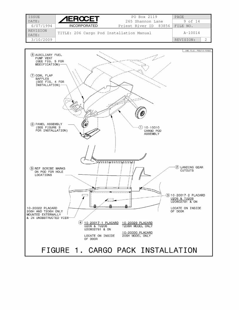
A. (Refer to Figure 1) Installation of this kit consists of:
1) Removing two existing nose gear access panel assemblies and modifying them according to Figure 2.
2) Modifying auxiliary fuel pump vent if pump installed in fuselage area.
3) Positioning cargo pack, drilling attaching holes, and installing rivnuts in fuselage skin.
4) Attaching cargo pack to fuselage with screws.
5) Modifying cowl flaps by adding baffles and/or extensions (some come modified).
2. INSTALLATION INSTRUCTIONS
A. (Refer to Figures 1 & 3) Installation of Nose Gear Access Panel Assemblies.
1) Remove existing panel assemblies and modify according to Figure 2. Prime with zinc chromate. Using existing screws, install modified assemblies according to Figures 1 and 3.
NOTE: Modified panel assemblies will permit servicing nose gear strut without removing cargo pack.
B. (Refer to Figure 5) Modification of Auxiliary Fuel Pump Vent. (Applicable only to serial numbers U20601605 through U20601618 and U20601633 and on when auxiliary fuel pump is located in fuselage.) (NOT APPLICABLE TO 206H AND T206H MODELS)
1) Remove existing vent tube drain from aircraft. 2) Install tube (1), line (4) and grommet (5) with connecting hose (2) and clamps (3).
C. (Refer to Figure 3) Installation of Cargo Pack Assembly.
1) Determine centerline of pack assembly (7) and mark on outside of pack on the aft
end. Centerline at forward end is determined by location of nose gear drag brace trough in pack assembly.
2) Mark centerline of aircraft on bottom fuselage skin across the station 100 area.

ISSUE DATE:
PO Box 2119 PAGE 265 Shannon Lane 6 of 14
6/07/1994 INCORPORATED Priest River ID 83856 FILE NO. REVISION DATE: TITLE: 206 Cargo Pod Installation Manual
A-10014
3/10/2009 REVISION: 2
3) Before fitting cargo pack, loosen lower wing lift strut fairings and slide them about 12” up; lift strut out of the way.
4) Place pack assembly (7) under the aircraft and align cutouts (2, Figure 1) with
landing gear springs. Position drag brace trough under nose gear drag brace. While pack assembly is being held in position, place a board crosswise under pack (7) and, using a jack, support the entire pack assembly firmly against fuselage. Be careful not to exert enough pressure to deform or spread edges of cargo pack.
5) Check centerline of pack assembly (7) with centerline marked on lower fuselage
skin. Check position of existing holes locations on pod (5, Figure 1) in cargo pack with fuselage skin below the door sills. Holes should align with lower rivet line on both sides of aircraft. Adjust pack fore and aft so that holes fall between rivets as shown in Figure 1.
6) When pack assembly (7) is positioned correctly, drill thirty-one #10 (.193) holes
through pack and fuselage, using hole locations scribed into the pack as a guide. CAUTION: Use a drill stop or some other device to assure that the drill does not go beyond the rivnut depth.
7) Remove pack assembly and enlarge #10 holes in fuselage to ¼” and cut slots as
shown (use a Rivet key punching tool if available). Install Rivets (8), (10), and (11) in fuselage skin.
8) Apply seal (2) to cargo pack (7) holding in place with masking tape. If a sealer caulk
is necessary, assure that it is non-corrosive to aluminum.
9) Attach pack assembly to fuselage using screws and washers (9). Use an ice pick to put holes in the seal for the fasteners.
D. (Refer to Figure 3) Installation of Seals and Fairings
1) Cement seals (3) to inboard side of fairings (5) and (12) using contact cement. Cut-
out area in seals should be centered in relation to rectangular openings in fairings, with split end of seal aft.
2) Split aft ends of fairings to match split ends of seals, place fairings over landing gear
springs, and position so bead at top of fairing matches bead edge of cargo pack. Using holes in fairings as a guide, drill five #26 (.147) holes in each side of cargo pack.
3) Remove fairings and enlarge #26 holes in cargo pack to #12 (.189). Install Rivnuts
(6) in cargo pack and reattach fairings, using screws (4).
4) Clean fairings (5 and 12) and prime with zinc chromate primer.

ISSUE DATE:
PO Box 2119 PAGE 265 Shannon Lane 7 of 14
6/07/1994 INCORPORATED Priest River ID 83856 FILE NO. REVISION DATE: TITLE: 206 Cargo Pod Installation Manual
A-10014
3/10/2009 REVISION: 2
E. (Refer to Figure 4) Cowl Flap Modification (Models 206, P206, U206 and Stationair)
(NOT APPLICABLE TO 206H AND T206H MODELS)
1) Disconnect cowl flap controls (4) and install links (7) and checknuts (9). Retain existing checknuts (6) on cowl flap control as shown. Cessna supplied links (#1213626-1) can be substituted for (7).
2) With cowl flap control in closed position, adjust cowl flaps (by turning links) until cowl
flap is 1.05” open at aft end. Openings to be measured between centerline of cowl flap at projected aft edge to lower firewall. Tighten checknuts (6) and (9).
3) Position baffles (1, 2, 3 & 5) with forward end of flange resting on flange of existing
baffles, aft end of baffle aligning with aft end of existing baffle, and lower corner of angular cutoff aligning with upper aft corner of existing baffle. Use Cessna part # 1213509-1, 2, 3, 4 for aircraft serial numbers through U20601604. Use Aerocet part #10-20010-R, L and Aerocet part #10-20012-R, L for aircraft serial numbers U20601605 and on. Cessna baffles #1213687-1, 2, 3, 4 may be substituted for the Aerocet baffle parts #10-20010 and #10-20012.
4) Using holes in baffles as a guide, drill twelve #10 (.193) holes in existing baffles.
Deburr holes and secure new baffles to existing baffles with screws (11) and (10). Options to substitute with rivets as shown in (11).
5) Adjust clearance of cowl flap baffles. Clearance between baffles and edge of cutout
in engine cowl should be 1/8” (.125). Adjust by hand, bending baffles. Check for clearance with engine drain tubes.
6) Check cowl flap travel. Cowl flaps should be 1.05” open when control is in “closed”
position and approximately 6.00” open when control is in “open” position.
F. (Refer to Figure 3) Cowl Flap Modification (Model TP206 & TU206) (NOT APPLICABLE TO 206H AND T206H MODELS)
NOTE: Baffles (1, 2, 3 & 5) are not required on turbocharged aircraft 1) Disconnect cowl flap controls (4) and install links (7) and checknuts. Retain existing
checknuts (6) on cowl flap control as shown.
2) With cowl flap control in closed position, adjust cowl flaps (by turning links) until cowl flap is 2.50” open at aft end. Tighten checknuts (6) and (9).
3) Check cowl flap travel. Cowl flaps should be 2.50” open when control is in “closed”
position, and approximately 8.00” open when control is in “open” position.

ISSUE DATE:
PO Box 2119 PAGE 265 Shannon Lane 8 of 14
6/07/1994 INCORPORATED Priest River ID 83856 FILE NO. REVISION DATE: TITLE: 206 Cargo Pod Installation Manual
A-10014
3/10/2009 REVISION: 2
G. Model T206H Airplane Exhaust Pipe Extension Installation
1) For Model T206H, also install exhaust pipe extension as follows:
a) Using Aerocet Part #10-20021 or Cessna Part #1250999-1 Exhaust Extension as
a template, drill four (4) Number 29 (0.136 inch diameter) holes in exhaust pipe.
NOTE: Extension must be flush with the exhaust pipe. It may be necessary to grind off approximately 1.5 inches of bead on exhaust pipe or reshape exhaust pipe in order to provide tight fit.
b) Attach extension using MS51861-34C Screws.
ISSUE DATE:
PO Box 2119 PAGE 265 Shannon Lane 9 of 14
6/07/1994 INCORPORATED Priest River ID 83856 FILE NO. REVISION DATE: TITLE: 206 Cargo Pod Installation Manual
A-10014
3/10/2009 REVISION: 2

ISSUE DATE:
PO Box 2119 PAGE 265 Shannon Lane 10 of 14
6/07/1994 INCORPORATED Priest River ID 83856 FILE NO. REVISION DATE: TITLE: 206 Cargo Pod Installation Manual
A-10014
3/10/2009 REVISION: 2

ISSUE DATE:
PO Box 2119 PAGE 265 Shannon Lane 11 of 14
6/07/1994 INCORPORATED Priest River ID 83856 FILE NO. REVISION DATE: TITLE: 206 Cargo Pod Installation Manual
A-10014
3/10/2009 REVISION: 2

ISSUE DATE:
PO Box 2119 PAGE 265 Shannon Lane 12 of 14
6/07/1994 INCORPORATED Priest River ID 83856 FILE NO. REVISION DATE: TITLE: 206 Cargo Pod Installation Manual
A-10014
3/10/2009 REVISION: 2

ISSUE DATE:
PO Box 2119 PAGE 265 Shannon Lane 13 of 14
6/07/1994 INCORPORATED Priest River ID 83856 FILE NO. REVISION DATE: TITLE: 206 Cargo Pod Installation Manual
A-10014
3/10/2009 REVISION: 2

PO Box 2119 ISSUE PAGE DATE: 265 Shannon Lane 14 of 146/07/1994 INCORPORATED Priest River ID 83856 FILE NO.
REVISION DATE: TITLE: 206 Cargo Pod Installation Manual
A-10014
3/10/2009 REVISION: 2