integrated access control and security … hardware manual.pdfintegrated access control and security...
TRANSCRIPT

Integrated Access Control and
Security Management System
HARDWARE MANUAL
new generation
building security

AxiomV™
Hardware Guide RBH Access Technologies Inc.
Copyright Notice
Copyright© 1995-2013 by RBH Access Technologies Inc.
All rights reserved Worldwide. Printed in Canada. This publication has been provided
pursuant to an agreement containing restrictions on its use. No part of this book may be
copied or distributed, transmitted, stored in a retrieval system, or translated into any
human or computer language, in any form or by any means, electronic, mechanical,
magnetic, manual, or otherwise, or disclosed to third parties without the express written
consent of RBH Access Technologies Inc., Brampton, Ontario, Canada.
Trademark
AxiomV™
is the trademark of RBH Access Technologies Inc. Windows is a trademark
of Microsoft Corporation. All other product names mentioned herein are the property of
their respective owners. Use of a term in this book should not be regarded as affecting
the validity of any trademark or service mark.
Disclaimer
This book is provided as is, without warranty of any kind, either express or implied,
including but not limited to performance, merchantability, or fitness for any particular
purpose. Neither RBH Access Technologies Inc. nor its dealers or distributors shall be
liable to any person or entity with respect to any liability, loss, nor damage, caused, or
alleged to have been caused directly or indirectly by this information. Further RBH
Access Technologies Inc. reserves the right to revise this publication, and to make
changes to the content hereof from time to time, without the obligation of RBH Access
Technologies Inc. to notify any person or organization of such revision or changes.
RBH ACCESS TECHNOLOGIES INC. 2 Automatic Road, Suite 108
Brampton, Ontario
CANADA
L6S 6K8
Tel: (905) 790-1515
Fax: (905) 790-3680
Email: [email protected]
WWW: www.rbh-access.com
RBH Access Technologies Inc. AxiomV™
Hardware Guide
i
C o n t e n t s
CHAPTER 1 INTRODUCING AXIOMV™
.................................................................. 1
CHAPTER 2 NETWORK CONTROLLER (NC-100) ................................................ 4 CONNECTION DETAILS ................................................................................................................................ 5
Power...................................................................................................................................................... 5 Host Interface ......................................................................................................................................... 5 C-NET CH1 and CH2 ............................................................................................................................. 6 D-NET CH1 and CH2 ............................................................................................................................ 6 Auxiliary Output ..................................................................................................................................... 6 Earth ....................................................................................................................................................... 6
DIP SWITCH SETTINGS ................................................................................................................................ 6 Controller Addressing ............................................................................................................................ 7 Master Controller ................................................................................................................................... 7 Slave Controller...................................................................................................................................... 7 Direct Connect........................................................................................................................................ 7 Computer Port Baud Rate Selection (Master Only) ............................................................................... 8 RS485 4 Wire Interface Selection (Master Only) ................................................................................... 8
PANEL RESET .............................................................................................................................................. 8 PC CONNECTION ......................................................................................................................................... 8 RS232 CONNECTION ................................................................................................................................... 9
Cable Specification ................................................................................................................................. 9 Maximum Cable Length ......................................................................................................................... 9
RS485 CONNECTION ................................................................................................................................. 10 Cable Specification ............................................................................................................................... 10 Maximum Cable Length ....................................................................................................................... 10
NC-100 NETWORKS .................................................................................................................................. 11 C-NET (CONTROLLER NETWORK) ............................................................................................................ 11
C-NET Cable ........................................................................................................................................ 13 C-NET Maximum Cable Length ........................................................................................................... 13
STATUS LED'S ........................................................................................................................................... 13 Computer/ Modem Port ........................................................................................................................ 13 C-NET LEDs ......................................................................................................................................... 13 D-NET LEDs ........................................................................................................................................ 13 Run LED ............................................................................................................................................... 13 Diagnostic LEDs 1 and 2 ..................................................................................................................... 13
D-NET DEVICE NETWORK ........................................................................................................................ 14 D-NET Maximum Cable Length ........................................................................................................... 16 D-NET Cable ........................................................................................................................................ 16 D-NET Termination .............................................................................................................................. 16
CLEARING NC-100 MEMORY .................................................................................................................... 17
CHAPTER 3 READER CONTROLLER (RC-2) ....................................................... 18 CONNECTION DETAILS .............................................................................................................................. 20
Output 1 A/B (Terminals 1, 2, 3) .......................................................................................................... 20 Output 2 A/B (Terminals 4, 5, 6) .......................................................................................................... 20 Output 3 A/B (Terminal 7) .................................................................................................................... 20 Output 4 A/B (Terminal 8) .................................................................................................................... 20 Auxiliary Power Output (Terminals 9, 10) ........................................................................................... 20 Reader A/B (Terminals 11 To 20) ......................................................................................................... 20 Inputs 1, 2, 3, And 4 A/B (Terminals 21 To 26) .................................................................................... 20 Lock Power DC Output (Terminals 27, 28 Side A) .............................................................................. 20 Lock AC Power Input (Terminals 29, 30 Side A) ................................................................................. 20 Main AC Power (Terminals 27, 28 Side B) .......................................................................................... 21 Powering From DC .............................................................................................................................. 21
AxiomV™
Hardware Guide RBH Access Technologies Inc.
ii
Backup Battery (Red and Black Leads) ................................................................................................ 21 Fire Release Input (Terminals 29, 30 Side B) ...................................................................................... 21 Tamper.................................................................................................................................................. 21
DIP SWITCH SETTINGS .............................................................................................................................. 22 RC-2 Addressing ................................................................................................................................... 22
STATUS LED'S ........................................................................................................................................... 22 Run ....................................................................................................................................................... 22 AC High ................................................................................................................................................ 22 AC Low ................................................................................................................................................. 22 Battery Trouble ..................................................................................................................................... 22 Reader Fuse .......................................................................................................................................... 23 Auxiliary Fuse ...................................................................................................................................... 23 Lock Fuse ............................................................................................................................................. 23 D-NET LED's ........................................................................................................................................ 23
BATTERY TEST .......................................................................................................................................... 23 BATTERY PROTECTION .............................................................................................................................. 23 INPUTS ...................................................................................................................................................... 24
RTE Request to Exit (Input 1A, 1B) ...................................................................................................... 24 Door Contact (Input 2A, 2B) ................................................................................................................ 24
INPUT CIRCUIT TYPES ............................................................................................................................... 25 OUTPUTS ................................................................................................................................................... 28
Switching Inductive Devices (Locks, Bells) .......................................................................................... 28 DEFAULT OUTPUT OPERATION .................................................................................................................. 29
Lock Output (Relay Outputs 1A, 1B) .................................................................................................... 29 Forced / Tamper (Relay Outputs 2A, 2B) ............................................................................................. 30 Door Held Open (Electronic Outputs 3A, 3B) ...................................................................................... 31 Alarm Shunt (Electronic Outputs 4A, 4B) ............................................................................................ 32
ACCESS POINT OPERATING MODES ........................................................................................................... 33 Two Person (Escort) ............................................................................................................................. 33 High Security ........................................................................................................................................ 33 Unlocked ............................................................................................................................................... 33 Tamper.................................................................................................................................................. 33 Lockout Alarm ...................................................................................................................................... 33 Door Held Open Warning .................................................................................................................... 33 Door Held Open Alarm ........................................................................................................................ 33 Keypad / Reader Combination ............................................................................................................. 33 Access Granted ..................................................................................................................................... 33 Access Denied ....................................................................................................................................... 33
READER CONNECTION DIAGRAMS ............................................................................................................. 34 Cable Specification ............................................................................................................................... 34 Maximum Cable Length ....................................................................................................................... 34 Cable Specification ............................................................................................................................... 35 Maximum Cable Length ....................................................................................................................... 35 Cable Specification ............................................................................................................................... 36 Maximum Cable Length ....................................................................................................................... 36 Cable Specification ............................................................................................................................... 37 Maximum Cable Length ....................................................................................................................... 37
CHAPTER 4 INPUT/OUTPUT CONTROLLER (IOC-16) ...................................... 38 CONNECTION DETAILS .............................................................................................................................. 39
Auxiliary Power Output ........................................................................................................................ 39 Backup Battery (Red and Black Lead) ................................................................................................. 39 AC Power ............................................................................................................................................. 39 Powering From DC .............................................................................................................................. 39 Fire Release Input (Terminals) ............................................................................................................. 39 Tamper.................................................................................................................................................. 39
RBH Access Technologies Inc. AxiomV™
Hardware Guide
iii
DIP SWITCH 1 SETTINGS ........................................................................................................................... 40 IOC-16 Addressing ............................................................................................................................... 40
STATUS LED'S ........................................................................................................................................... 41 Run ....................................................................................................................................................... 41 AC High ................................................................................................................................................ 41 AC Low ................................................................................................................................................. 41 Battery Trouble ..................................................................................................................................... 41 Auxiliary Fuse ...................................................................................................................................... 41 Network LEDs ...................................................................................................................................... 41
BATTERY TEST .......................................................................................................................................... 41 BATTERY PROTECTION .............................................................................................................................. 41
Input / Output Selection ........................................................................................................................ 42 INPUTS ...................................................................................................................................................... 43 OUTPUTS ................................................................................................................................................... 43
Switching Inductive Devices (Locks, Bells) .......................................................................................... 44 Fail Safe Output Operation .................................................................................................................. 44 Elevator Control ................................................................................................................................... 44
CHAPTER 5 NRC2000 & NURC2000......................................................................... 47 WIRING ..................................................................................................................................................... 48 MODIFICATION .......................................................................................................................................... 49
CHAPTER 6 PC-100 ..................................................................................................... 50 POWER: ..................................................................................................................................................... 50 LEDS ........................................................................................................................................................ 50
NC-100 SPECIFICATION ............................................................................................. 52
RC-2 SPECIFICATION ................................................................................................. 53
IOC-16 SPECIFICATION ............................................................................................. 54
NRC-2000 SPECIFICATION ........................................................................................ 55
NURC-2000 SPECIFICATION ..................................................................................... 56
PC-100 SPECIFICATION ............................................................................................. 57
CABLE SPECIFICATION ............................................................................................ 58 PC To Controller .................................................................................................................................. 58 C-NET: (NC-100 to NC-100)................................................................................................................ 58 D-NET: (NC-100 to RC-2, IOC-16) ..................................................................................................... 58 RC-2 to Reader: .................................................................................................................................... 58 Input / Output Port Circuit Loop:......................................................................................................... 58
INDEX .............................................................................................................................. 59

Chapter 1 Introducing AxiomV
™
RBH Access Technologies Inc. AxiomV™
Hardware Guide
1
C h a p t e r 1
I n t r o d u c i n g A x i o m V™
The RBH AxiomV™
System combines access control, building management, and
security monitoring in a highly integrated and expandable package. AxiomV™
Security Management Software runs on a standard IBM compatible PC and is
designed for use in installations ranging from simple two door systems to
complex systems covering multiple sites and containing thousands of access
points and tens of thousands of cardholders.
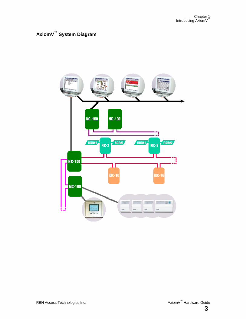
The system can monitor over 1,000 networked controller units (NC-100) with
each controller capable of monitoring eight card readers and 320 input/output
points. Remote site monitoring capability is 4,096 readers and 65,535
input/output points. Local site capacity exceeds 8,000 readers and 250,000
input/output points. A minimum configuration consists of a PC, a single
controller unit (NC-100) and a single reader controller (RC-2) that allows
connection of two card readers, eight inputs and eight outputs.
The PC is used for data entry, setting up the database, and monitoring activity on
the system. Once the database is downloaded to the controllers, the PC is not
required for system operation. Should the PC be powered down, the NC-100
controller will perform all access and other control functions, including logging
up to 100,000 events. When the connection is restored, the log is reported to the
PC.
AxiomV™
Security Management software runs on all standard PC networks. On
a networked PC system, all control functionality and system monitoring is
available at all PCs. Networked systems are usually necessary on larger
installations where a single operator can not handle the volume of incoming
messages.
The AxiomV™
system hardware consists of a number of different networks. The
controller network (C-NET) links up to fifteen controller units to a single port
on the PC. This network can be directly connected to a serial port on the PC in
which case a separate serial port is required for each network. Controller
number one in the network is designated the master and is connected to the PC
and all other controllers are referred to as slaves.
All controllers in the network are connected together in a fault tolerant, high
speed Arcnet LAN. Arcnet is a highly reliable networking architecture and is
widely used in industrial control applications. This LAN module transfers data
at speeds of 156k bits/second to 2.5M bits/second and when wired in a ring is
immune to a single point of attack. The network will continue to operate
normally with a single short or a cut on any inter- controller connection.
The controllers use a powerful Motorola 32-bit micro controller and come
standard with 256k bytes of RAM. A plug in memory expansion board allows
the memory to be expanded to 16 Megabytes. All RAM is battery backed by a
Chapter 1 Introducing AxiomV
™
AxiomV™
Hardware Guide RBH Access Technologies Inc.
2
replaceable lithium battery. A built in watchdog circuit monitors the operation
of the controller and performs a system reset if an out of control situation is
detected.
Each controller has a second local network (D-NET) for connection to card
reader controllers (RC-2) and input/output boards (IOC-16). This RS485
network operates at 38400 bits/second and is also wired in a fault tolerant ring
providing protection from a single point of failure. Devices can be placed on the
local network up to 3000 feet (1000 meters) apart and the network supports up to
twenty devices (up to four RC-2s and up to sixteen IOC-16s). The controller
polls each device on the network and processes any data reported such as access
verification requests and input status changes.
A RC-2 (Reader Controller) supports two access points. Each RC-2 can
monitor two reader or reader/keypad units; eight input points and control eight
output points. Inputs and outputs are programmable for dedicated access point
functions such as door contact, request to exit button and door lock or can be
used as general purpose I/O.
All operating information including times, facility codes, card formats and other
parameters are stored locally in non-volatile memory in the RC-2. If
communication is lost with the controller, the RC-2 can be programmed to
operate in facility code mode where access is granted upon presentation of a
valid facility code only. The system reverts to normal operation when
communication resumes with the controller.
IOC-16 (Input/Output Controller) devices have sixteen ports, each configurable
as an input or output. Outputs are programmable as normally energized or
normally de-energized and a fire panel input facilitates fail-safe operation.
Seven input configurations are provided ranging from simple normally closed
contacts to two EOL loops for high security applications.
The system architecture utilized by AxiomV™
is extremely powerful, flexible,
and expandable. As new devices are developed for the system, compatibility
will be maintained with existing network devices, ensuring continued
possibilities for system upgrading and expansion.
Chapter 1 Introducing AxiomV
™
RBH Access Technologies Inc. AxiomV™
Hardware Guide
3
AxiomV™
System Diagram
Chapter 2 NC-100
AxiomV™
Hardware Guide RBH Access Technologies Inc.
4
C h a p t e r 2
N e t w o r k C o n t r o l l e r ( N C - 1 0 0 )
The AxiomV™
access control system consists of one or more network controllers
(NC-100). All information required by the controller is downloaded from the
PC and stored locally in battery backed flash memory. This information includes
configuration data, cardholder records, access levels, schedules, and all other
records necessary for the operation of the system. The controller operates
independent of the PC and all decision-making is performed locally, even in the
event of total power loss.
The NC-100 contains a powerful 32-bit micro-controller and has a base RAM
configuration of 256k, expandable to 16M. Advanced features including 32-bit
processing, built in high speed LAN interface, Flash RAM, and fault tolerant
design make the NC-100 one of the most powerful and versatile controllers
currently available.
Chapter 2 NC-100
RBH Access Technologies Inc. AxiomV™
Hardware Guide
5
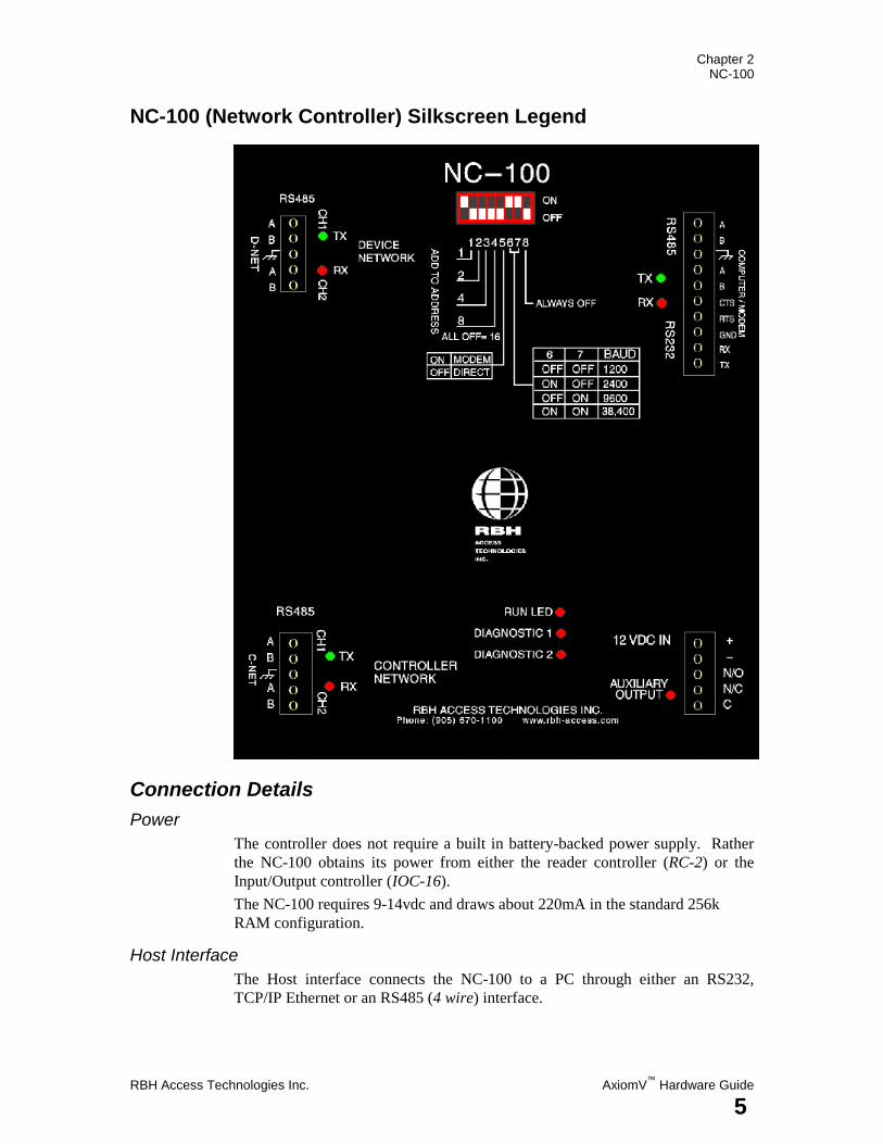
NC-100 (Network Controller) Silkscreen Legend
Connection Details
Power
The controller does not require a built in battery-backed power supply. Rather
the NC-100 obtains its power from either the reader controller (RC-2) or the
Input/Output controller (IOC-16).
The NC-100 requires 9-14vdc and draws about 220mA in the standard 256k
RAM configuration.
Host Interface
The Host interface connects the NC-100 to a PC through either an RS232,
TCP/IP Ethernet or an RS485 (4 wire) interface.
Chapter 2 NC-100
AxiomV™
Hardware Guide RBH Access Technologies Inc.
6
C-NET CH1 and CH2
The C-NET (Controller Network) connects NC-100 controllers together on a
high-speed bi-directional fault tolerant network. CH2 on the master controller
connects to CH1 on the next NC-100 on the network and so on. CH2 on the last
controller in the network is wired back to CH1 on the first controller to form a
ring (see C-NET diagram on page 14).
D-NET CH1 and CH2
D-NET (Device Network) connects local device controllers (RC-2, IOC-16) to
the NC-100 controller on a high-speed bi-directional fault tolerant network.
Connect CH2 on the NC-100 to CH1 on the first device controller, and connect
CH2 on this device controller to CH1 on the next device controller on the D-
NET and so on. Connect CH2 on the last device controller back to CH1 of the
NC-100 to complete the ring (see the D-NET diagram on page17).
Auxiliary Output
This is a dry contact relay output rated for 2A@30vdc that does not have a valid
use at this time.
Earth
The controller contains several layers of protection against induced high voltage
transients from static discharge, lightning, and power line spikes. In order for
this protection to be fully effective, a good connection to earth ground is
essential. Wire this connection to a metal cold water pipe or similar structure.
Do not connect directly to the AC earth. Use 16 AWG or heavier cable and keep
the length as short as possible (less than 50 feet [15meters]).
Although the NC-100 has three possible ground connection points, the ground
connections are normally made at the PC. This leaves the ground connections at
the C-NET and D-NET ports available for cable shield connections.
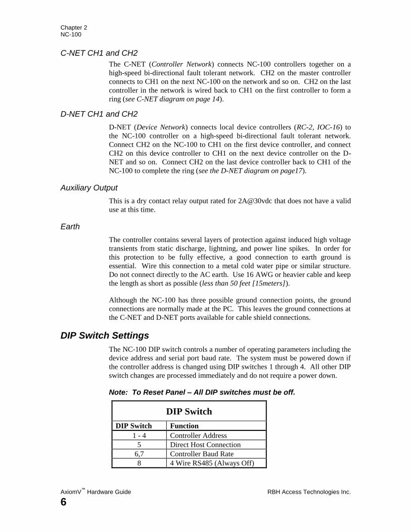
DIP Switch Settings
The NC-100 DIP switch controls a number of operating parameters including the
device address and serial port baud rate. The system must be powered down if
the controller address is changed using DIP switches 1 through 4. All other DIP
switch changes are processed immediately and do not require a power down.
Note: To Reset Panel – All DIP switches must be off.
DIP Switch
DIP Switch Function
1 - 4 Controller Address
5 Direct Host Connection
6,7 Controller Baud Rate
8 4 Wire RS485 (Always Off)
Chapter 2 NC-100
RBH Access Technologies Inc. AxiomV™
Hardware Guide
7
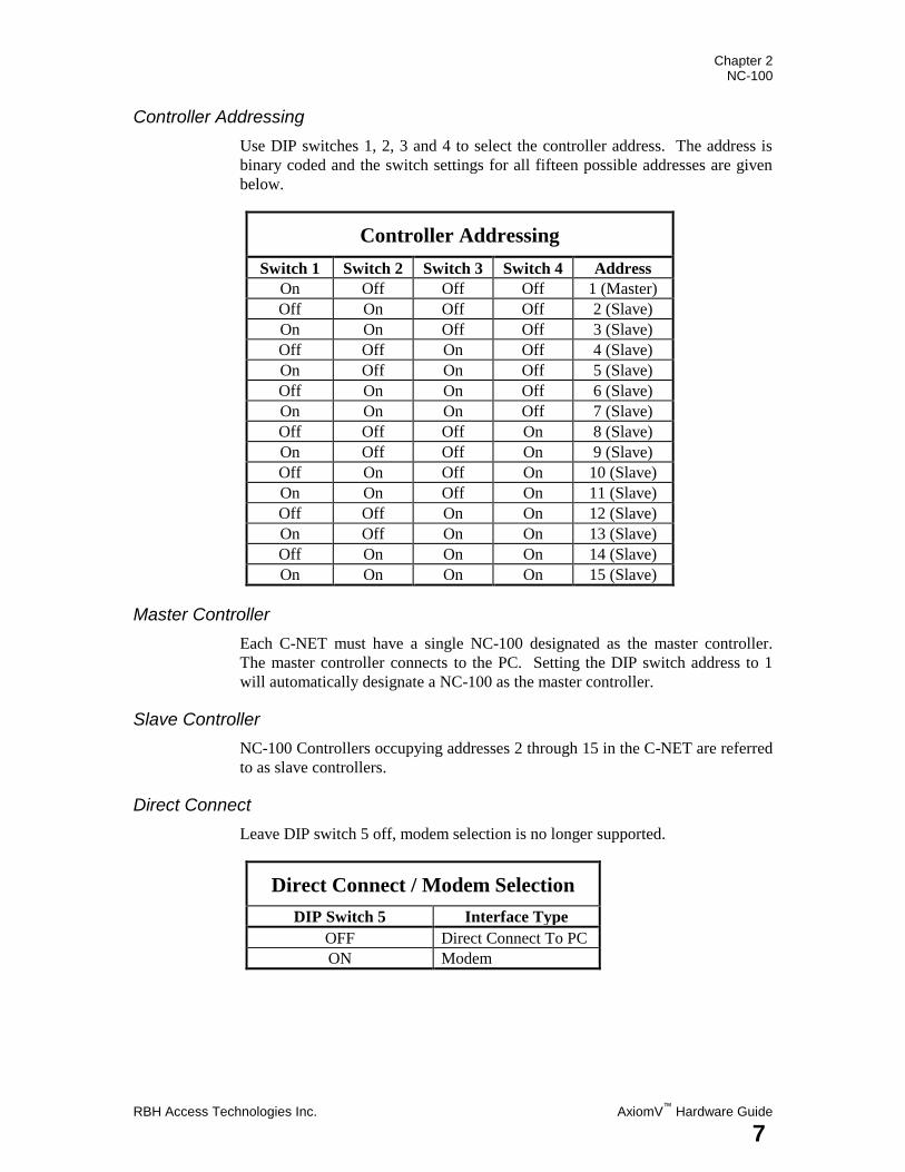
Controller Addressing
Use DIP switches 1, 2, 3 and 4 to select the controller address. The address is
binary coded and the switch settings for all fifteen possible addresses are given
below.
Controller Addressing
Switch 1 Switch 2 Switch 3 Switch 4 Address
On Off Off Off 1 (Master)
Off On Off Off 2 (Slave)
On On Off Off 3 (Slave)
Off Off On Off 4 (Slave)
On Off On Off 5 (Slave)
Off On On Off 6 (Slave)
On On On Off 7 (Slave)
Off Off Off On 8 (Slave)
On Off Off On 9 (Slave)
Off On Off On 10 (Slave)
On On Off On 11 (Slave)
Off Off On On 12 (Slave)
On Off On On 13 (Slave)
Off On On On 14 (Slave)
On On On On 15 (Slave)
Master Controller
Each C-NET must have a single NC-100 designated as the master controller.
The master controller connects to the PC. Setting the DIP switch address to 1
will automatically designate a NC-100 as the master controller.
Slave Controller
NC-100 Controllers occupying addresses 2 through 15 in the C-NET are referred
to as slave controllers.
Direct Connect
Leave DIP switch 5 off, modem selection is no longer supported.
Direct Connect / Modem Selection
DIP Switch 5 Interface Type
OFF Direct Connect To PC
ON Modem
Chapter 2 NC-100
AxiomV™
Hardware Guide RBH Access Technologies Inc.
8
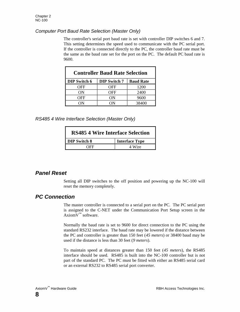
Computer Port Baud Rate Selection (Master Only)
The controller's serial port baud rate is set with controller DIP switches 6 and 7.
This setting determines the speed used to communicate with the PC serial port.
If the controller is connected directly to the PC, the controller baud rate must be
the same as the baud rate set for the port on the PC. The default PC baud rate is
9600.
Controller Baud Rate Selection
DIP Switch 6 DIP Switch 7 Baud Rate
OFF OFF 1200
ON OFF 2400
OFF ON 9600
ON ON 38400
RS485 4 Wire Interface Selection (Master Only)
RS485 4 Wire Interface Selection
DIP Switch 8 Interface Type
OFF 4 Wire
Panel Reset
Setting all DIP switches to the off position and powering up the NC-100 will
reset the memory completely.
PC Connection
The master controller is connected to a serial port on the PC. The PC serial port
is assigned to the C-NET under the Communication Port Setup screen in the
AxiomV™
software.
Normally the baud rate is set to 9600 for direct connection to the PC using the
standard RS232 interface. The baud rate may be lowered if the distance between
the PC and controller is greater than 150 feet (45 meters) or 38400 baud may be
used if the distance is less than 30 feet (9 meters).
To maintain speed at distances greater than 150 feet (45 meters), the RS485
interface should be used. RS485 is built into the NC-100 controller but is not
part of the standard PC. The PC must be fitted with either an RS485 serial card
or an external RS232 to RS485 serial port converter.
Chapter 2 NC-100
RBH Access Technologies Inc. AxiomV™
Hardware Guide
9
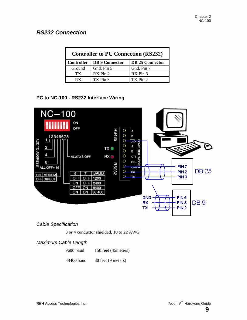
RS232 Connection
Controller to PC Connection (RS232)
Controller DB 9 Connector DB 25 Connector
Ground Gnd. Pin 5 Gnd. Pin 7
TX RX Pin 2 RX Pin 3
RX TX Pin 3 TX Pin 2
PC to NC-100 - RS232 Interface Wiring
Cable Specification
3 or 4 conductor shielded, 18 to 22 AWG
Maximum Cable Length
9600 baud 150 feet (45meters)
38400 baud 30 feet (9 meters)
Chapter 2 NC-100
AxiomV™
Hardware Guide RBH Access Technologies Inc.
10
RS485 Connection
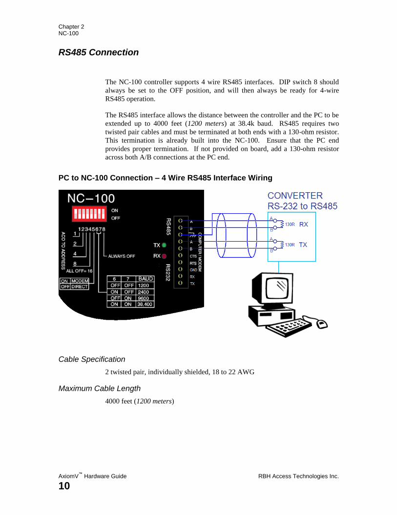
The NC-100 controller supports 4 wire RS485 interfaces. DIP switch 8 should
always be set to the OFF position, and will then always be ready for 4-wire
RS485 operation.
The RS485 interface allows the distance between the controller and the PC to be
extended up to 4000 feet (1200 meters) at 38.4k baud. RS485 requires two
twisted pair cables and must be terminated at both ends with a 130-ohm resistor.
This termination is already built into the NC-100. Ensure that the PC end
provides proper termination. If not provided on board, add a 130-ohm resistor
across both A/B connections at the PC end.
PC to NC-100 Connection – 4 Wire RS485 Interface Wiring
Cable Specification
2 twisted pair, individually shielded, 18 to 22 AWG
Maximum Cable Length
4000 feet (1200 meters)
Chapter 2 NC-100
RBH Access Technologies Inc. AxiomV™
Hardware Guide
11
NC-100 Networks
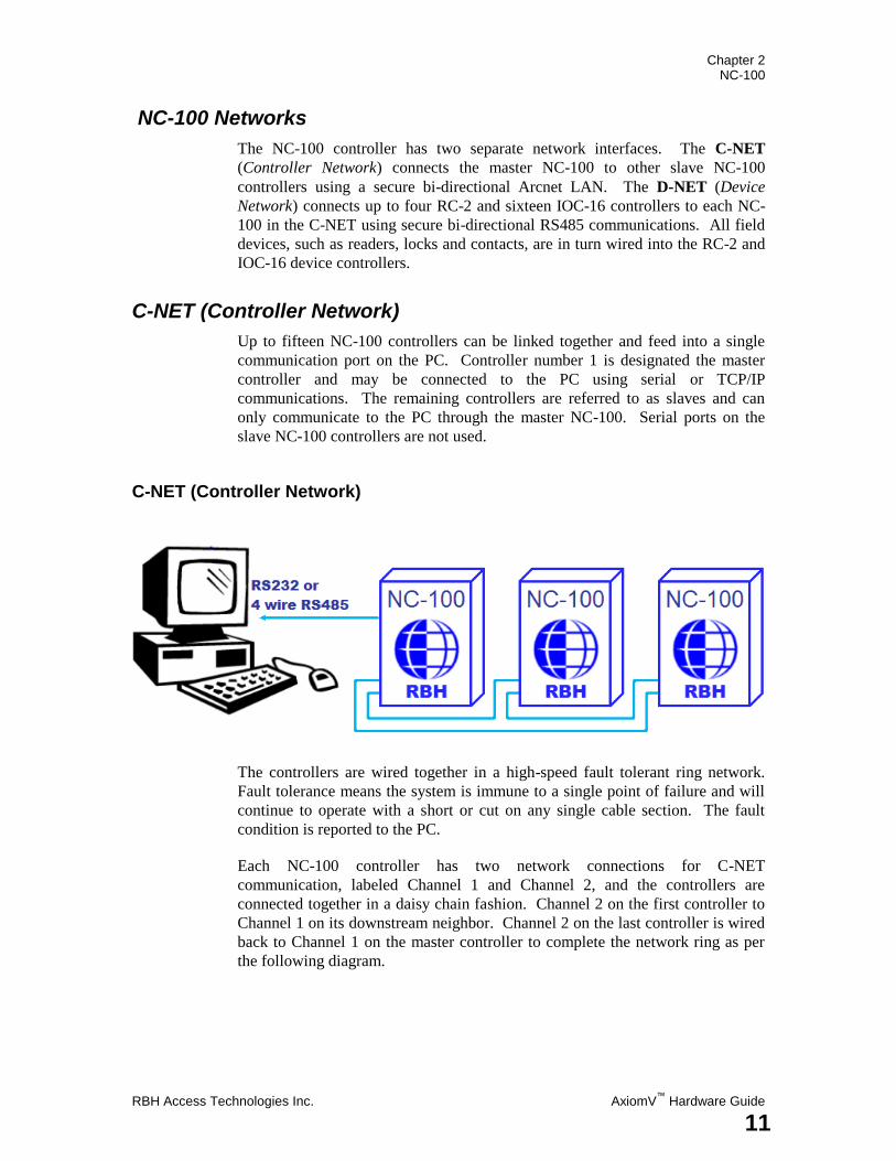
The NC-100 controller has two separate network interfaces. The C-NET
(Controller Network) connects the master NC-100 to other slave NC-100
controllers using a secure bi-directional Arcnet LAN. The D-NET (Device
Network) connects up to four RC-2 and sixteen IOC-16 controllers to each NC-
100 in the C-NET using secure bi-directional RS485 communications. All field
devices, such as readers, locks and contacts, are in turn wired into the RC-2 and
IOC-16 device controllers.
C-NET (Controller Network)
Up to fifteen NC-100 controllers can be linked together and feed into a single
communication port on the PC. Controller number 1 is designated the master
controller and may be connected to the PC using serial or TCP/IP
communications. The remaining controllers are referred to as slaves and can
only communicate to the PC through the master NC-100. Serial ports on the
slave NC-100 controllers are not used.
C-NET (Controller Network)
The controllers are wired together in a high-speed fault tolerant ring network.
Fault tolerance means the system is immune to a single point of failure and will
continue to operate with a short or cut on any single cable section. The fault
condition is reported to the PC.
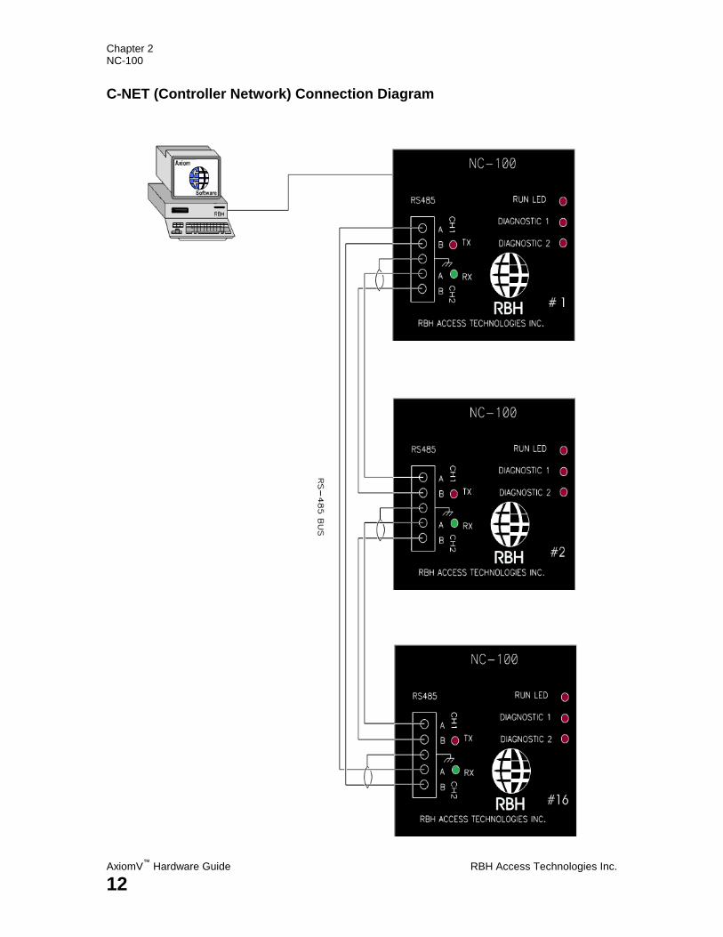
Each NC-100 controller has two network connections for C-NET
communication, labeled Channel 1 and Channel 2, and the controllers are
connected together in a daisy chain fashion. Channel 2 on the first controller to
Channel 1 on its downstream neighbor. Channel 2 on the last controller is wired
back to Channel 1 on the master controller to complete the network ring as per
the following diagram.
Chapter 2 NC-100
AxiomV™
Hardware Guide RBH Access Technologies Inc.
12
C-NET (Controller Network) Connection Diagram
Chapter 2 NC-100
RBH Access Technologies Inc. AxiomV™
Hardware Guide
13
C-NET Cable
Use 20 to 22 AWG shielded stranded twisted pair cable for all C-NET
connections.
C-NET Maximum Cable Length
The maximum distance for any link in the C-NET ring is 2500 feet (760 meters)
and the total ring length cannot exceed 10000 feet (3000 meters).
Status LED's
Computer/ Modem Port
The computer port has two LEDs to show the flow of data between the NC-100
controller and PC. The red RX LED flashes when the controller receives data.
The green TX LED flashes when the controller transmits data. If the controller
is connected directly to the PC, the status LED flashes continuously.
C-NET LEDs
The inter-controller network (C-NET) has two status LEDs. The red RX LED
flashes when data is received from another controller. The green TX LED
flashes when the controller transmits data. On a properly functioning system the
C-NET LEDs flash continuously and may appear to be on all the time.
D-NET LEDs
The device-controller network (D-NET) has two status LEDs. The red RX LED
flashes when data is received from a network device (RC-2, IOC-16). The green
TX LED flashes when data is transmitted by the NC-100 to any device controller
on the D-NET. On a properly functioning system the D-NET LEDs flash
continuously and may appear to be on all the time.
Run LED
The run LED flashes every half-second and indicates the system is running
normally.
Diagnostic LEDs 1 and 2
These LEDs are used for factory diagnostics only.
1 – Flashes when receiving a message from other controller.
2 – Flashes in normal mode (sending messages to other controllers).
Chapter 2 NC-100
AxiomV™
Hardware Guide RBH Access Technologies Inc.
14
D-NET Device Network
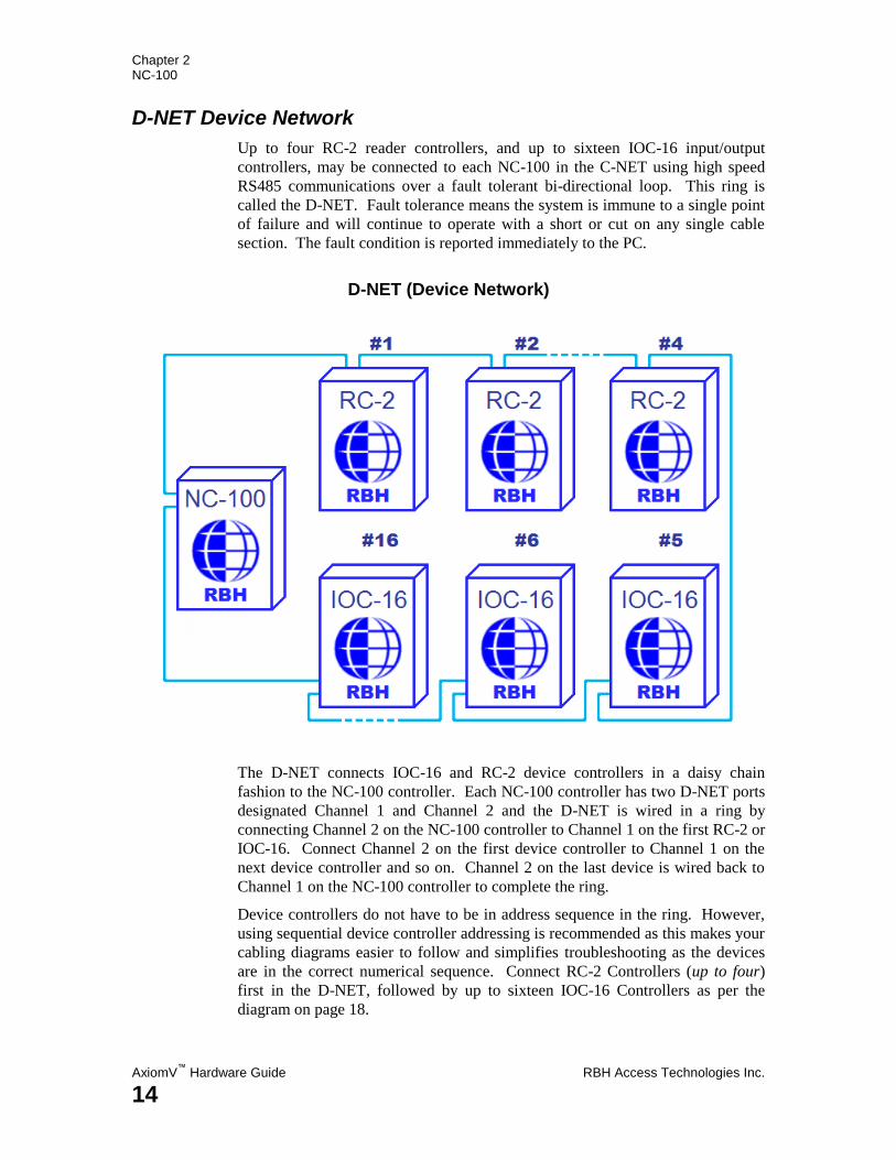
Up to four RC-2 reader controllers, and up to sixteen IOC-16 input/output
controllers, may be connected to each NC-100 in the C-NET using high speed
RS485 communications over a fault tolerant bi-directional loop. This ring is
called the D-NET. Fault tolerance means the system is immune to a single point
of failure and will continue to operate with a short or cut on any single cable
section. The fault condition is reported immediately to the PC.
D-NET (Device Network)
The D-NET connects IOC-16 and RC-2 device controllers in a daisy chain
fashion to the NC-100 controller. Each NC-100 controller has two D-NET ports
designated Channel 1 and Channel 2 and the D-NET is wired in a ring by
connecting Channel 2 on the NC-100 controller to Channel 1 on the first RC-2 or
IOC-16. Connect Channel 2 on the first device controller to Channel 1 on the
next device controller and so on. Channel 2 on the last device is wired back to
Channel 1 on the NC-100 controller to complete the ring.
Device controllers do not have to be in address sequence in the ring. However,
using sequential device controller addressing is recommended as this makes your
cabling diagrams easier to follow and simplifies troubleshooting as the devices
are in the correct numerical sequence. Connect RC-2 Controllers (up to four)
first in the D-NET, followed by up to sixteen IOC-16 Controllers as per the
diagram on page 18.

Chapter 2 NC-100
RBH Access Technologies Inc. AxiomV™
Hardware Guide
15
Device Controller Address Assignment
Address Device Controller
1 – 4 RC-2
5 – 20 IOC-16
D-NET (Device Network) Connection Diagram
Chapter 2 NC-100
AxiomV™
Hardware Guide RBH Access Technologies Inc.
16
D-NET Maximum Cable Length
The maximum distance for any link in the ring is 3000 feet (900 meters) and the
total ring length cannot exceed 15,000 feet (4600 meters).
D-NET Cable
Use 20 to 22 AWG shielded twisted pair cable for all D-NET connections.
Shielded cable is recommended to minimize problems that can arise in
electrically noisy environments. In addition, shielded cable may be necessary to
prevent the network from interfering with signals on other cables in the same
trunk.
D-NET Termination
There are some controllers/devices that do not have termination built into the
unit. These devices are: UNC500, PC100, and SafeSuite. In most cases,
termination is not needed because the devices are connected to other devices on
the network that will have termination built in. Units which terminate
automatically are the NC100, RC2, and IOC16. The NRC and NURC (trimmed
down replacements for the RC-2) can be terminated using jumpers JP2, JP3, and
JP4 or JP1, JP2, and JP3 (respectfully). All three jumpers must be ON.
SafeSuite units are normally installed with Riser boards which have termination
on each leg of the 485 connections so nothing else needs to be done to terminate
these units. PC100s will normally be added to networks which have terminated
devices such as RC2s or IOC16s. If possible, always put a device that can be
terminated at the start and end of the line. For example; if you have a system
where the PC100 is mixed with NRCs or NURCs, make sure that PC100 is not
the last device. This will allow you to set the jumpers on the NRC or NURC for
termination on the first and last device. Because the UNC does not have
termination jumpers, the first device connected to the UNC500 will have
termination as will the last device on that DNET.
Chapter 2 NC-100
RBH Access Technologies Inc. AxiomV™
Hardware Guide
17
Clearing NC-100 Memory
The NC-100 battery backed RAM can be completely cleared by the following
process.
1. Power down the controller.
2. Set all eight DIP switches to OFF.
3. Power up the controller.
4. Wait until the two diagnostic LEDs flash rapidly.
5. Power down the controller and set the DIP switches to configure the
controller.
6. Reapply power to the controller.
Clearing the RAM in this manner is only necessary in the rare occasion where
RAM is completely corrupted and the system is unable to communicate with the
PC.
Chapter 3 RC-2
AxiomV™
Hardware Guide RBH Access Technologies Inc.
18
C h a p t e r 3
R e a d e r C o n t r o l l e r ( R C - 2 )
Each RC-2 monitors two readers or reader/keypad units as well as eight inputs
and controls eight outputs. RBH recommends that RC-2‟s be used for dedicated
access point operation. However in certain instances inputs and outputs may be
individually configured for general I/O purposes.
The RC-2 has two sides, labeled A and B, and each side implements an
independent access point. Typically an access point includes a reader, door
contact, request to exit button and programmable outputs for lock, forced entry,
door held open and alarm shunt.
Each RC-2 includes two built in power supplies. The 1Amp reader power
supply provides both 5 and 12 volt DC power for reader devices. An additional
1Amp@12volts is available on the auxiliary power output to power other devices
such as motion detectors and warning devices. The system requires a 40 or 80
VA transformer and a rechargeable backup battery.
A separate 12/24-volt power supply is provided for powering door locks.
The RC-2 performs extensive system status monitoring and provides a high
degree of local feedback on system status for the technician. AC power, battery
voltage, reader, and auxiliary fuses are all monitored. Status LEDs indicate the
status of all inputs and outputs, AC fault, low voltage, fuse blown,
communication activity, and run information.
Chapter 3 RC-2
RBH Access Technologies Inc. AxiomV™
Hardware Guide
19
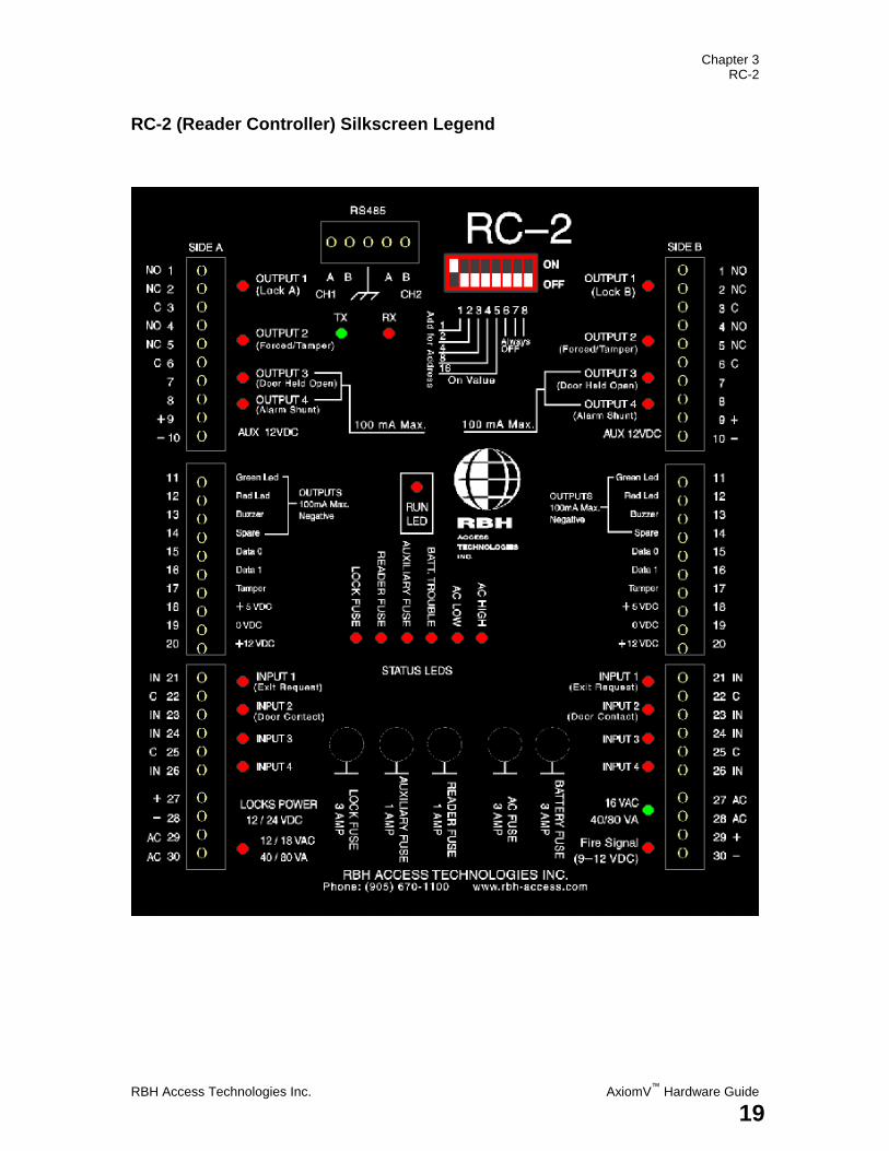
RC-2 (Reader Controller) Silkscreen Legend
Chapter 3 RC-2
AxiomV™
Hardware Guide RBH Access Technologies Inc.
20
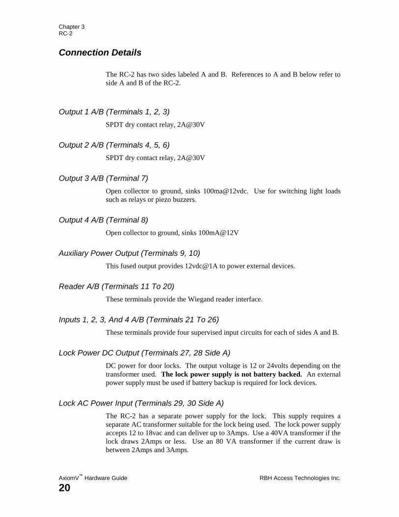
Connection Details
The RC-2 has two sides labeled A and B. References to A and B below refer to
side A and B of the RC-2.
Output 1 A/B (Terminals 1, 2, 3)
SPDT dry contact relay, 2A@30V
Output 2 A/B (Terminals 4, 5, 6)
SPDT dry contact relay, 2A@30V
Output 3 A/B (Terminal 7)
Open collector to ground, sinks 100ma@12vdc. Use for switching light loads
such as relays or piezo buzzers.
Output 4 A/B (Terminal 8)
Open collector to ground, sinks 100mA@12V
Auxiliary Power Output (Terminals 9, 10)
This fused output provides 12vdc@1A to power external devices.
Reader A/B (Terminals 11 To 20)
These terminals provide the Wiegand reader interface.
Inputs 1, 2, 3, And 4 A/B (Terminals 21 To 26)
These terminals provide four supervised input circuits for each of sides A and B.
Lock Power DC Output (Terminals 27, 28 Side A)
DC power for door locks. The output voltage is 12 or 24volts depending on the
transformer used. The lock power supply is not battery backed. An external
power supply must be used if battery backup is required for lock devices.
Lock AC Power Input (Terminals 29, 30 Side A)
The RC-2 has a separate power supply for the lock. This supply requires a
separate AC transformer suitable for the lock being used. The lock power supply
accepts 12 to 18vac and can deliver up to 3Amps. Use a 40VA transformer if the
lock draws 2Amps or less. Use an 80 VA transformer if the current draw is
between 2Amps and 3Amps.
Chapter 3 RC-2
RBH Access Technologies Inc. AxiomV™
Hardware Guide
21
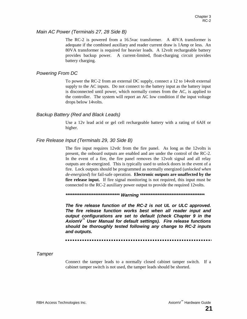
Main AC Power (Terminals 27, 28 Side B)
The RC-2 is powered from a 16.5vac transformer. A 40VA transformer is
adequate if the combined auxiliary and reader current draw is 1Amp or less. An
80VA transformer is required for heavier loads. A 12volt rechargeable battery
provides backup power. A current-limited, float-charging circuit provides
battery charging.
Powering From DC
To power the RC-2 from an external DC supply, connect a 12 to 14volt external
supply to the AC inputs. Do not connect to the battery input as the battery input
is disconnected until power, which normally comes from the AC, is applied to
the controller. The system will report an AC low condition if the input voltage
drops below 14volts.
Backup Battery (Red and Black Leads)
Use a 12v lead acid or gel cell rechargeable battery with a rating of 6AH or
higher.
Fire Release Input (Terminals 29, 30 Side B)
The fire input requires 12vdc from the fire panel. As long as the 12volts is
present, the onboard outputs are enabled and are under the control of the RC-2.
In the event of a fire, the fire panel removes the 12volt signal and all relay
outputs are de-energized. This is typically used to unlock doors in the event of a
fire. Lock outputs should be programmed as normally energized (unlocked when
de-energized) for fail-safe operation. Electronic outputs are unaffected by the
fire release input. If fire signal monitoring is not required, this input must be
connected to the RC-2 auxiliary power output to provide the required 12volts.
******************************* Warning *************************************
The fire release function of the RC-2 is not UL or ULC approved.
The fire release function works best when all reader input and
output configurations are set to default (check Chapter 9 in the
AxiomV™
User Manual for default settings). Fire release functions
should be thoroughly tested following any change to RC-2 inputs
and outputs.
Tamper
Connect the tamper leads to a normally closed cabinet tamper switch. If a
cabinet tamper switch is not used, the tamper leads should be shorted.
Chapter 3 RC-2
AxiomV™
Hardware Guide RBH Access Technologies Inc.
22
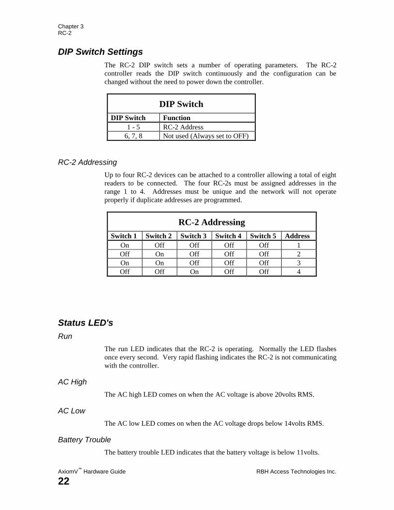
DIP Switch Settings
The RC-2 DIP switch sets a number of operating parameters. The RC-2
controller reads the DIP switch continuously and the configuration can be
changed without the need to power down the controller.
DIP Switch
DIP Switch Function
1 - 5 RC-2 Address
6, 7, 8 Not used (Always set to OFF)
RC-2 Addressing
Up to four RC-2 devices can be attached to a controller allowing a total of eight
readers to be connected. The four RC-2s must be assigned addresses in the
range 1 to 4. Addresses must be unique and the network will not operate
properly if duplicate addresses are programmed.
RC-2 Addressing
Switch 1 Switch 2 Switch 3 Switch 4 Switch 5 Address
On Off Off Off Off 1
Off On Off Off Off 2
On On Off Off Off 3
Off Off On Off Off 4
Status LED's
Run
The run LED indicates that the RC-2 is operating. Normally the LED flashes
once every second. Very rapid flashing indicates the RC-2 is not communicating
with the controller.
AC High
The AC high LED comes on when the AC voltage is above 20volts RMS.
AC Low
The AC low LED comes on when the AC voltage drops below 14volts RMS.
Battery Trouble
The battery trouble LED indicates that the battery voltage is below 11volts.
Chapter 3 RC-2
RBH Access Technologies Inc. AxiomV™
Hardware Guide
23
Reader Fuse
The reader fuse LED indicates the 1Amp reader fuse is blown. This fuse is
blown if the reader 5 or 12volt output is overloaded.
Auxiliary Fuse
The auxiliary fuse LED indicates the 1Amp auxiliary fuse is blown.
Lock Fuse
LED on indicates the lock fuse is blown.
D-NET LED's
The local-controller network has two status LEDs. The red RX LED flashes
when data is received from the controller. The green TX LED flashes when data
is transmitted by the RC-2. Normally the status LEDs flash continuously.
Battery Test
A dynamic battery test is performed under scheduled control. During the test a
1Amp load is switched across the battery and the voltage is monitored. At the
end of the test a pass or fail message is reported to the PC. The frequency and
duration of the test are programmable from the AxiomV™
software. Typically
the battery is tested once every day and the test duration is thirty seconds.
Battery Protection
The backup battery is protected from deep discharge and possible irreversible
damage during a prolonged ac power failure. The battery voltage is continuously
monitored and will disconnect if the voltage drops below 10 volts.
Chapter 3 RC-2
AxiomV™
Hardware Guide RBH Access Technologies Inc.
24
Inputs
The RC-2 has eight fully supervised inputs, four on side A and four on side B.
Each input is individually programmable from the PC. The RC-2 employs
digital filtering to eliminate the effect of interference on the input loops and
verifies all loop changes before reporting to the controller. Loop resistance is
continuously monitored using a built in eight bit analog to digital converter and
can be viewed from the PC, providing the service technician with a valuable
diagnostic tool and allowing marginal circuit loops to be detected and repaired
before a full blown fault develops.
Each input has four states: Restore, Alarm, Trouble, and Illegal. Trouble is
reported if a short or break is detected on a supervised circuit and illegal is
reported if the measured loop resistance lies between valid states. For example,
if the circuit type is programmed as „2 resistor normally closed‟, 1k represents a
restored state and 2k represents an alarm state. If the loop resistance changes by
more than 15% but not enough to enter the next state, an illegal state is reported.
RTE Request to Exit (Input 1A, 1B)
The RTE input is connected to a push button mounted on the door or to a motion
detector mounted near the door. A normally open or normally closed button can
be used and the circuit type can be programmed from the PC. Activating the
RTE input will unlock the door. The RTE can be disabled by time zone. This
input can be used as a general purpose input if RTE operation is not required. If
not used, leave the default RTE settings in the AxiomV™
software configuration.
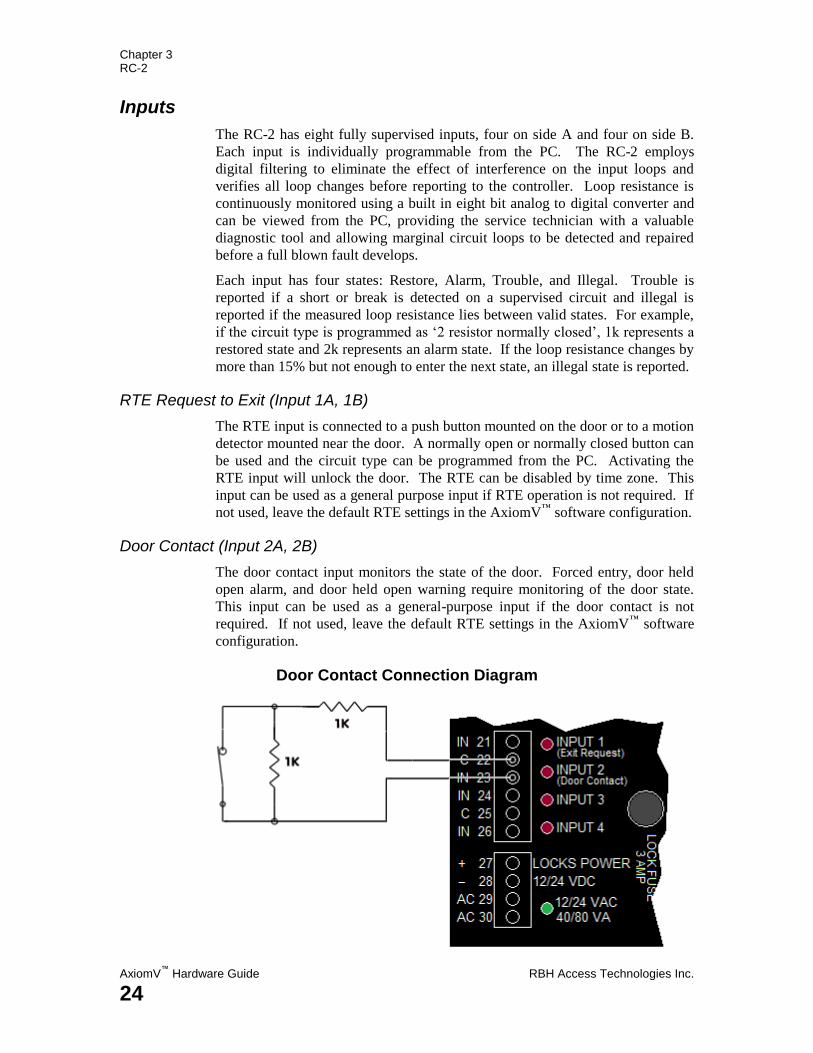
Door Contact (Input 2A, 2B)
The door contact input monitors the state of the door. Forced entry, door held
open alarm, and door held open warning require monitoring of the door state.
This input can be used as a general-purpose input if the door contact is not
required. If not used, leave the default RTE settings in the AxiomV™
software
configuration.
Door Contact Connection Diagram
Chapter 3 RC-2
RBH Access Technologies Inc. AxiomV™
Hardware Guide
25
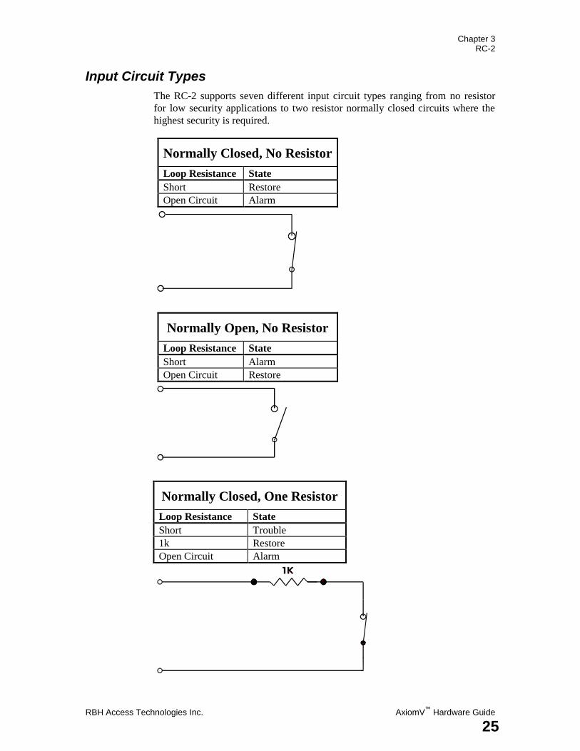
Input Circuit Types
The RC-2 supports seven different input circuit types ranging from no resistor
for low security applications to two resistor normally closed circuits where the
highest security is required.
Normally Closed, No Resistor
Loop Resistance State
Short Restore
Open Circuit Alarm
Normally Open, No Resistor
Loop Resistance State
Short Alarm
Open Circuit Restore
Normally Closed, One Resistor
Loop Resistance State
Short Trouble
1k Restore
Open Circuit Alarm
Chapter 3 RC-2
AxiomV™
Hardware Guide RBH Access Technologies Inc.
26
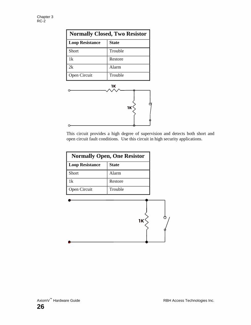
Normally Closed, Two Resistor
Loop Resistance State
Short Trouble
1k Restore
2k Alarm
Open Circuit Trouble
This circuit provides a high degree of supervision and detects both short and
open circuit fault conditions. Use this circuit in high security applications.
Normally Open, One Resistor
Loop Resistance State
Short Alarm
1k Restore
Open Circuit Trouble
Chapter 3 RC-2
RBH Access Technologies Inc. AxiomV™
Hardware Guide
27
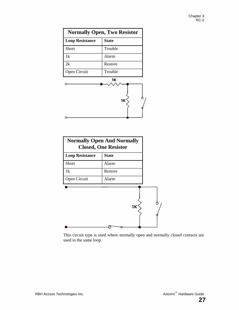
Normally Open, Two Resistor
Loop Resistance State
Short Trouble
1k Alarm
2k Restore
Open Circuit Trouble
Normally Open And Normally
Closed, One Resistor
Loop Resistance State
Short Alarm
1k Restore
Open Circuit Alarm
This circuit type is used where normally open and normally closed contacts are
used in the same loop.
Chapter 3 RC-2
AxiomV™
Hardware Guide RBH Access Technologies Inc.
28
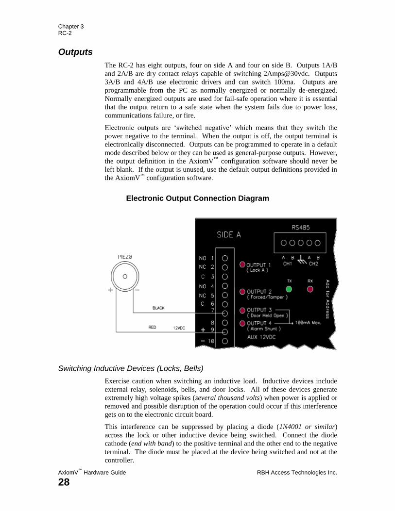
Outputs
The RC-2 has eight outputs, four on side A and four on side B. Outputs 1A/B
and 2A/B are dry contact relays capable of switching 2Amps@30vdc. Outputs
3A/B and 4A/B use electronic drivers and can switch 100ma. Outputs are
programmable from the PC as normally energized or normally de-energized.
Normally energized outputs are used for fail-safe operation where it is essential
that the output return to a safe state when the system fails due to power loss,
communications failure, or fire.
Electronic outputs are „switched negative‟ which means that they switch the
power negative to the terminal. When the output is off, the output terminal is
electronically disconnected. Outputs can be programmed to operate in a default
mode described below or they can be used as general-purpose outputs. However,
the output definition in the AxiomV™
configuration software should never be
left blank. If the output is unused, use the default output definitions provided in
the AxiomV™
configuration software.
Electronic Output Connection Diagram
Switching Inductive Devices (Locks, Bells)
Exercise caution when switching an inductive load. Inductive devices include
external relay, solenoids, bells, and door locks. All of these devices generate
extremely high voltage spikes (several thousand volts) when power is applied or
removed and possible disruption of the operation could occur if this interference
gets on to the electronic circuit board.
This interference can be suppressed by placing a diode (1N4001 or similar)
across the lock or other inductive device being switched. Connect the diode
cathode (end with band) to the positive terminal and the other end to the negative
terminal. The diode must be placed at the device being switched and not at the
controller.
Chapter 3 RC-2
RBH Access Technologies Inc. AxiomV™
Hardware Guide
29
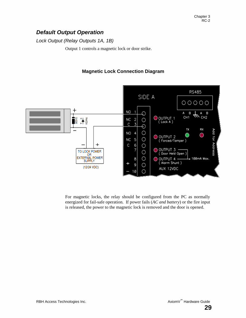
Default Output Operation
Lock Output (Relay Outputs 1A, 1B)
Output 1 controls a magnetic lock or door strike.
Magnetic Lock Connection Diagram
For magnetic locks, the relay should be configured from the PC as normally
energized for fail-safe operation. If power fails (AC and battery) or the fire input
is released, the power to the magnetic lock is removed and the door is opened.
Chapter 3 RC-2
AxiomV™
Hardware Guide RBH Access Technologies Inc.
30
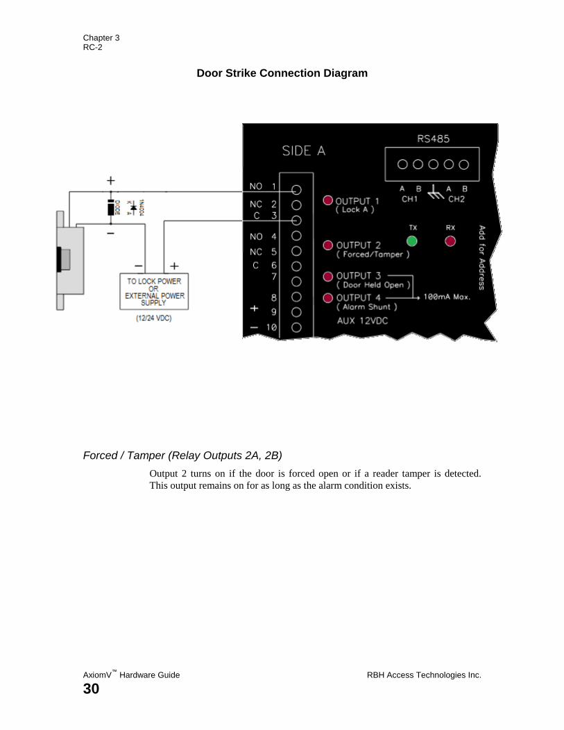
Door Strike Connection Diagram
Forced / Tamper (Relay Outputs 2A, 2B)
Output 2 turns on if the door is forced open or if a reader tamper is detected.
This output remains on for as long as the alarm condition exists.
Chapter 3 RC-2
RBH Access Technologies Inc. AxiomV™
Hardware Guide
31
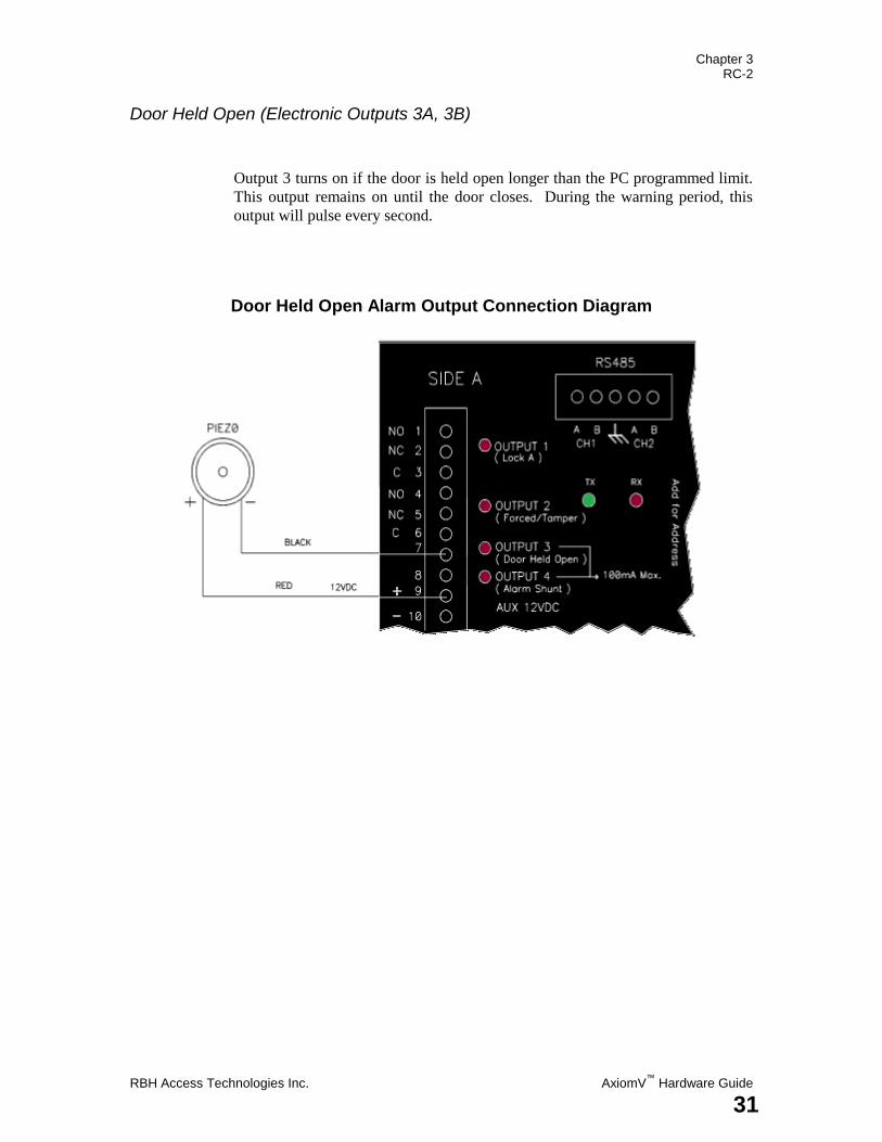
Door Held Open (Electronic Outputs 3A, 3B)
Output 3 turns on if the door is held open longer than the PC programmed limit.
This output remains on until the door closes. During the warning period, this
output will pulse every second.
Door Held Open Alarm Output Connection Diagram
Chapter 3 RC-2
AxiomV™
Hardware Guide RBH Access Technologies Inc.
32
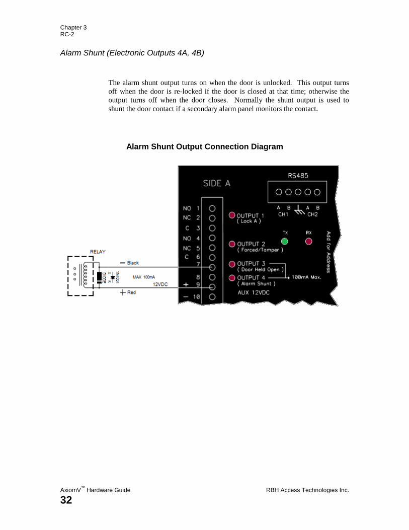
Alarm Shunt (Electronic Outputs 4A, 4B)
The alarm shunt output turns on when the door is unlocked. This output turns
off when the door is re-locked if the door is closed at that time; otherwise the
output turns off when the door closes. Normally the shunt output is used to
shunt the door contact if a secondary alarm panel monitors the contact.
Alarm Shunt Output Connection Diagram
Chapter 3 RC-2
RBH Access Technologies Inc. AxiomV™
Hardware Guide
33
Access Point Operating Modes
Two Person (Escort)
The Red LED flashes slowly.
In Escort mode, two valid cards are required for access. The reader Buzzer
beeps rapidly after the first card is presented. A second valid card must be
presented within ten seconds for access to be granted.
High Security
The Red LED flashes quickly.
In high security mode, only cardholders with high security clearance are allowed
access.
Unlocked
The green LED turns on to indicate the door is unlocked.
Tamper
The Buzzer sounds continuously.
Lockout Alarm
The Buzzer beeps rapidly.
A lockout alarm occurs when a user-defined number of „Access Denied‟
messages occur. These messages can include „Invalid Card Number‟, „No
Access at this Time‟, „No Access at this Reader‟, or „Invalid PIN Code‟.
Door Held Open Warning
The Buzzer beeps slowly.
Door Held Open Alarm
The Buzzer beeps rapidly.
Keypad / Reader Combination
The Buzzer emits a short beep every second after a card is presented, until a PIN
is entered.
Access Granted
The Buzzer emits one long beep and the green LED turns on for the duration of
the unlock time.
Access Denied
The Buzzer emits two short beeps and the red LED flashes twice.
Chapter 3 RC-2
AxiomV™
Hardware Guide RBH Access Technologies Inc.
34
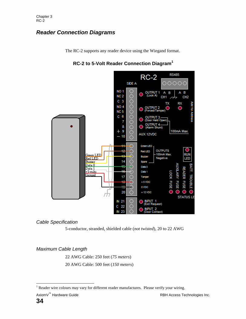
Reader Connection Diagrams
The RC-2 supports any reader device using the Wiegand format.
RC-2 to 5-Volt Reader Connection Diagram1
Cable Specification
5-conductor, stranded, shielded cable (not twisted), 20 to 22 AWG
Maximum Cable Length
22 AWG Cable: 250 feet (75 meters)
20 AWG Cable: 500 feet (150 meters)
1 Reader wire colours may vary for different reader manufactures. Please verify your wiring.
Chapter 3 RC-2
RBH Access Technologies Inc. AxiomV™
Hardware Guide
35
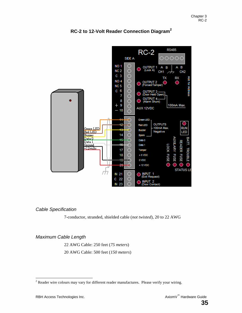
RC-2 to 12-Volt Reader Connection Diagram2
Cable Specification
7-conductor, stranded, shielded cable (not twisted), 20 to 22 AWG
Maximum Cable Length
22 AWG Cable: 250 feet (75 meters)
20 AWG Cable: 500 feet (150 meters)
2 Reader wire colours may vary for different reader manufactures. Please verify your wiring.

Chapter 3 RC-2
AxiomV™
Hardware Guide RBH Access Technologies Inc.
36
RC-2 to 24-Volt Reader Connection Diagram3
Cable Specification
6-conductor, stranded, shielded cable (not twisted), 20 to 22 AWG
Maximum Cable Length
22 AWG Cable: 250 feet (75 meters)
20 AWG Cable: 500 feet (150 meters)
3 Reader wire colours may vary for different reader manufactures. Please verify your wiring.
Chapter 3 RC-2
RBH Access Technologies Inc. AxiomV™
Hardware Guide
37
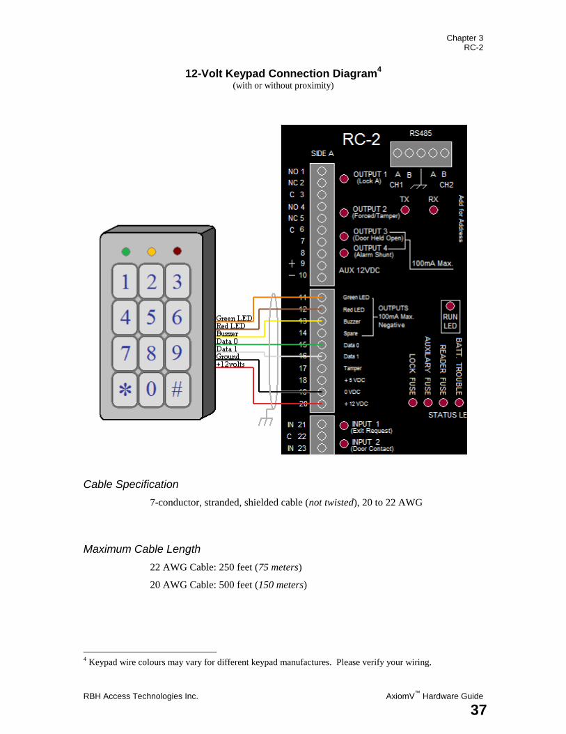
12-Volt Keypad Connection Diagram4
(with or without proximity)
Cable Specification
7-conductor, stranded, shielded cable (not twisted), 20 to 22 AWG
Maximum Cable Length
22 AWG Cable: 250 feet (75 meters)
20 AWG Cable: 500 feet (150 meters)
4 Keypad wire colours may vary for different keypad manufactures. Please verify your wiring.
Chapter 4 IOC-16
AxiomV™
Hardware Guide RBH Access Technologies Inc.
38
C h a p t e r 4
I n p u t / O u t p u t C o n t r o l l e r ( I O C - 1 6 )
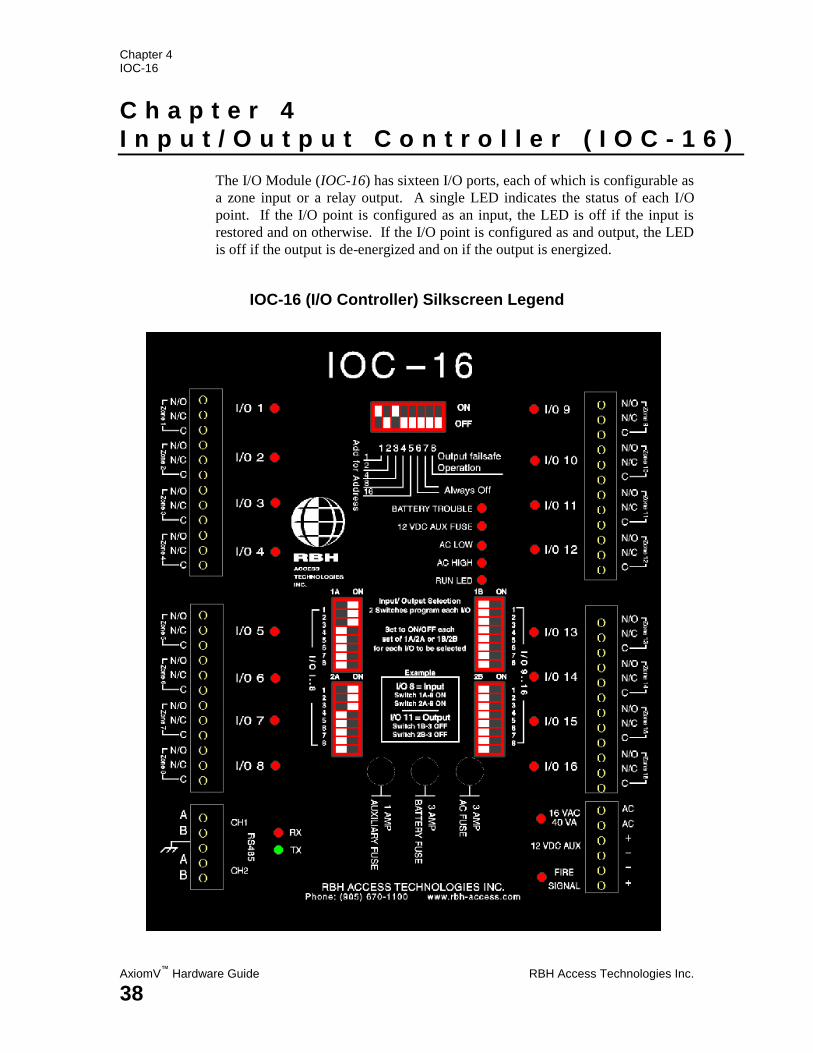
The I/O Module (IOC-16) has sixteen I/O ports, each of which is configurable as
a zone input or a relay output. A single LED indicates the status of each I/O
point. If the I/O point is configured as an input, the LED is off if the input is
restored and on otherwise. If the I/O point is configured as and output, the LED
is off if the output is de-energized and on if the output is energized.
IOC-16 (I/O Controller) Silkscreen Legend
Chapter 4 IOC-16
RBH Access Technologies Inc. AxiomV™
Hardware Guide
39
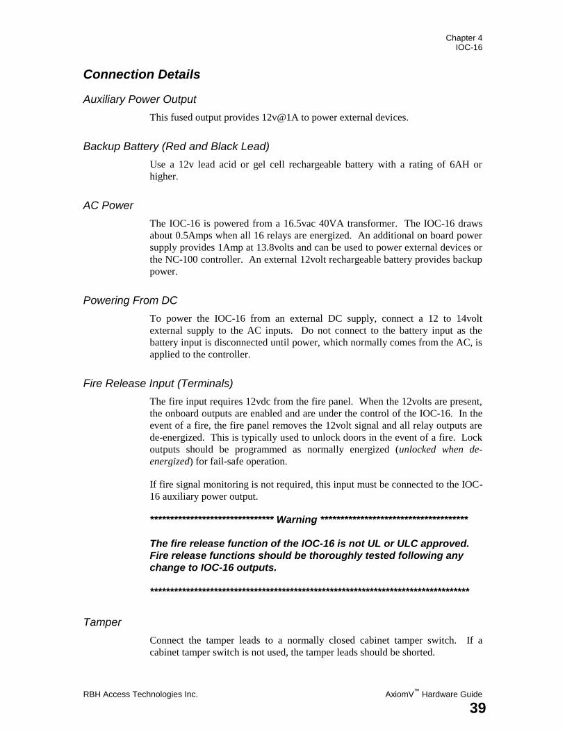
Connection Details
Auxiliary Power Output
This fused output provides 12v@1A to power external devices.
Backup Battery (Red and Black Lead)
Use a 12v lead acid or gel cell rechargeable battery with a rating of 6AH or
higher.
AC Power
The IOC-16 is powered from a 16.5vac 40VA transformer. The IOC-16 draws
about 0.5Amps when all 16 relays are energized. An additional on board power
supply provides 1Amp at 13.8volts and can be used to power external devices or
the NC-100 controller. An external 12volt rechargeable battery provides backup
power.
Powering From DC
To power the IOC-16 from an external DC supply, connect a 12 to 14volt
external supply to the AC inputs. Do not connect to the battery input as the
battery input is disconnected until power, which normally comes from the AC, is
applied to the controller.
Fire Release Input (Terminals)
The fire input requires 12vdc from the fire panel. When the 12volts are present,
the onboard outputs are enabled and are under the control of the IOC-16. In the
event of a fire, the fire panel removes the 12volt signal and all relay outputs are
de-energized. This is typically used to unlock doors in the event of a fire. Lock
outputs should be programmed as normally energized (unlocked when de-
energized) for fail-safe operation.
If fire signal monitoring is not required, this input must be connected to the IOC-
16 auxiliary power output.
******************************* Warning *************************************
The fire release function of the IOC-16 is not UL or ULC approved.
Fire release functions should be thoroughly tested following any
change to IOC-16 outputs.
********************************************************************************
Tamper
Connect the tamper leads to a normally closed cabinet tamper switch. If a
cabinet tamper switch is not used, the tamper leads should be shorted.
Chapter 4 IOC-16
AxiomV™
Hardware Guide RBH Access Technologies Inc.
40
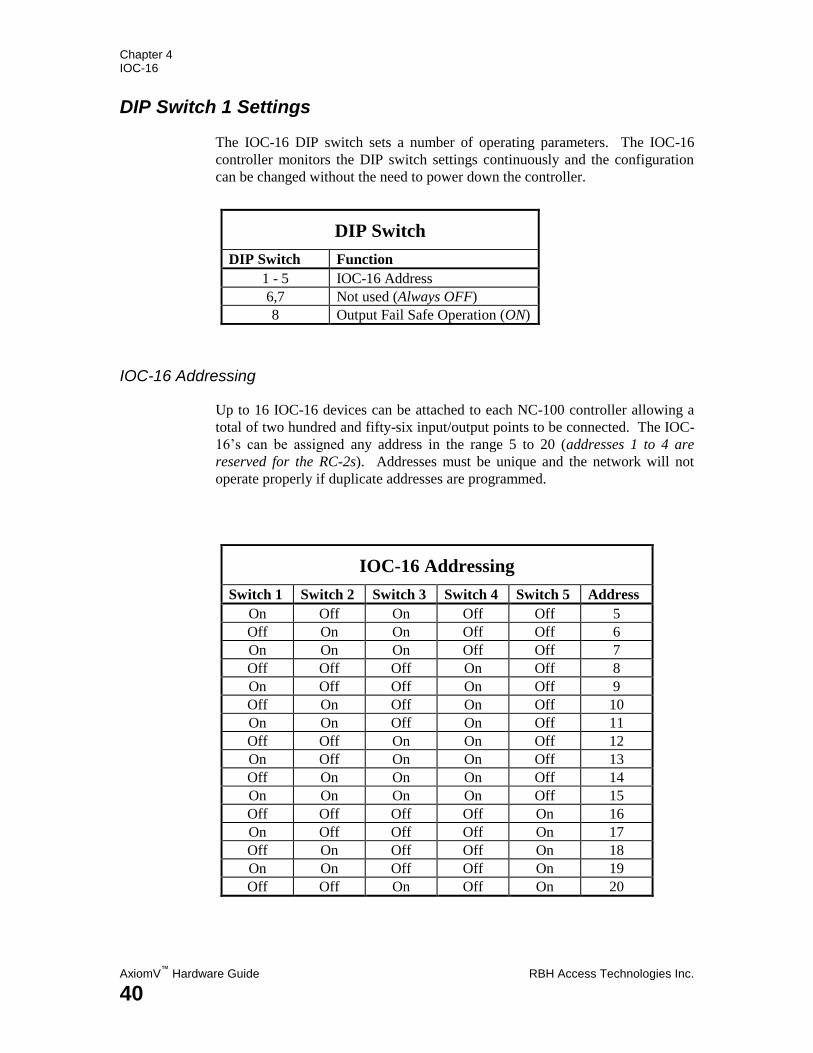
DIP Switch 1 Settings
The IOC-16 DIP switch sets a number of operating parameters. The IOC-16
controller monitors the DIP switch settings continuously and the configuration
can be changed without the need to power down the controller.
DIP Switch
DIP Switch Function
1 - 5 IOC-16 Address
6,7 Not used (Always OFF)
8 Output Fail Safe Operation (ON)
IOC-16 Addressing
Up to 16 IOC-16 devices can be attached to each NC-100 controller allowing a
total of two hundred and fifty-six input/output points to be connected. The IOC-
16‟s can be assigned any address in the range 5 to 20 (addresses 1 to 4 are
reserved for the RC-2s). Addresses must be unique and the network will not
operate properly if duplicate addresses are programmed.
IOC-16 Addressing
Switch 1 Switch 2 Switch 3 Switch 4 Switch 5 Address
On Off On Off Off 5
Off On On Off Off 6
On On On Off Off 7
Off Off Off On Off 8
On Off Off On Off 9
Off On Off On Off 10
On On Off On Off 11
Off Off On On Off 12
On Off On On Off 13
Off On On On Off 14
On On On On Off 15
Off Off Off Off On 16
On Off Off Off On 17
Off On Off Off On 18
On On Off Off On 19
Off Off On Off On 20
Chapter 4 IOC-16
RBH Access Technologies Inc. AxiomV™
Hardware Guide
41
Status LED's
Run
The run LED indicates that the IOC-16 is operating. Normally the LED flashes
once every second. Very rapid flashing indicates the IOC-16 is not
communicating with the NC-100 controller.
AC High
The AC high LED comes on when the AC voltage is above 20volts RMS.
AC Low
The AC low LED comes on when the AC voltage drops below 14volts RMS.
Battery Trouble
The battery trouble LED indicates that the battery voltage is below 11volts.
Auxiliary Fuse
The auxiliary fuse LED indicates the 1Amp auxiliary fuse is blown.
Network LEDs
The local-controller network has two status LEDs. The red RX LED flashes
when data is received from the controller. The green TX LED flashes when data
is transmitted by the IOC-16. Normally the status LEDs flash continuously.
Battery Test
A dynamic battery test is performed under scheduled control. During the test a
1Amp load is switched across the battery and the voltage is monitored. At the
end of the test a pass or fail message is reported to the PC. The frequency and
duration of the test are programmable from the PC. Typically the battery is
tested once every day and the test duration is thirty seconds.
Battery Protection
The backup battery is protected from deep discharge and possible irreversible
damage during a prolonged ac power failure. The battery voltage is continuously
monitored and disconnected if the voltage drops below 10volts.
Chapter 4 IOC-16
AxiomV™
Hardware Guide RBH Access Technologies Inc.
42
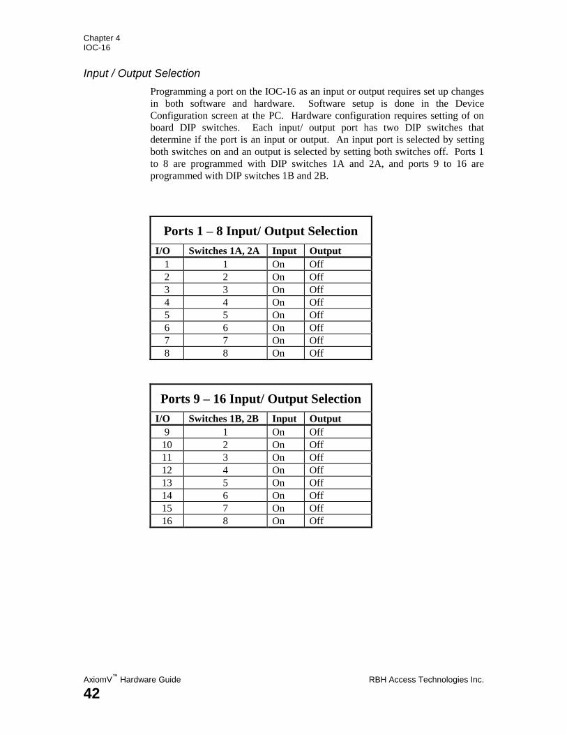
Input / Output Selection
Programming a port on the IOC-16 as an input or output requires set up changes
in both software and hardware. Software setup is done in the Device
Configuration screen at the PC. Hardware configuration requires setting of on
board DIP switches. Each input/ output port has two DIP switches that
determine if the port is an input or output. An input port is selected by setting
both switches on and an output is selected by setting both switches off. Ports 1
to 8 are programmed with DIP switches 1A and 2A, and ports 9 to 16 are
programmed with DIP switches 1B and 2B.
Ports 1 – 8 Input/ Output Selection
I/O Switches 1A, 2A Input Output
1 1 On Off
2 2 On Off
3 3 On Off
4 4 On Off
5 5 On Off
6 6 On Off
7 7 On Off
8 8 On Off
Ports 9 – 16 Input/ Output Selection
I/O Switches 1B, 2B Input Output
9 1 On Off
10 2 On Off
11 3 On Off
12 4 On Off
13 5 On Off
14 6 On Off
15 7 On Off
16 8 On Off
Chapter 4 IOC-16
RBH Access Technologies Inc. AxiomV™
Hardware Guide
43
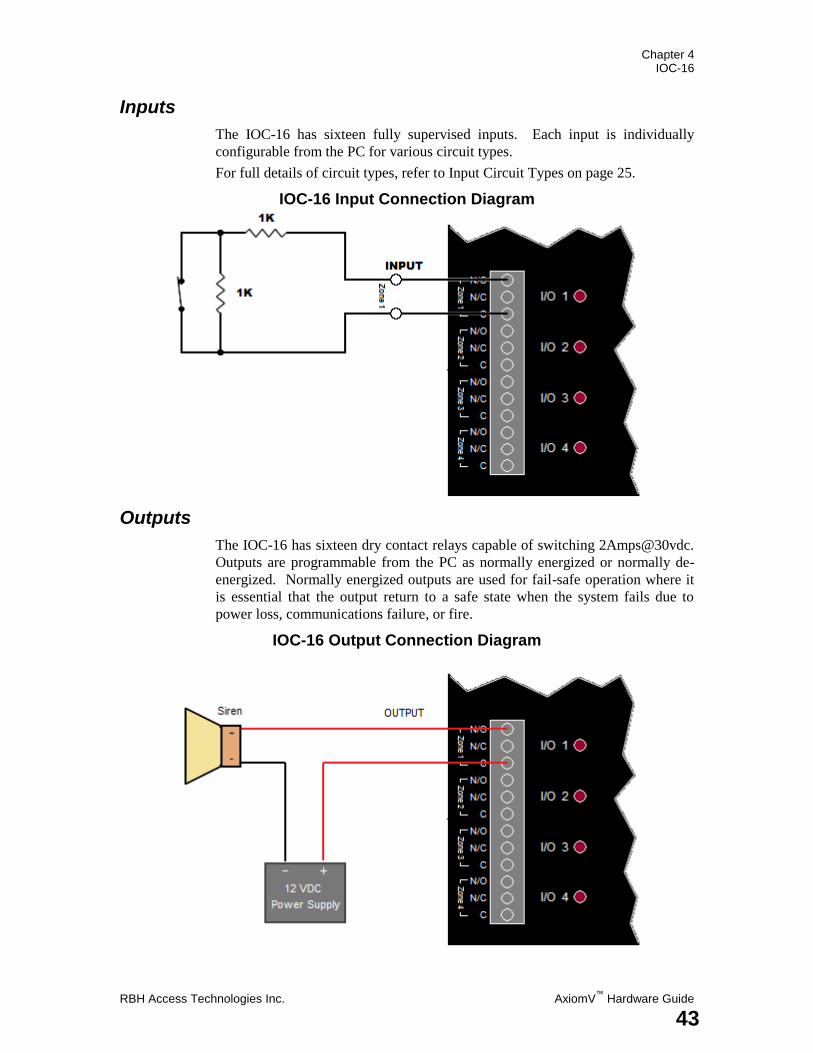
Inputs
The IOC-16 has sixteen fully supervised inputs. Each input is individually
configurable from the PC for various circuit types.
For full details of circuit types, refer to Input Circuit Types on page 25.
IOC-16 Input Connection Diagram
Outputs
The IOC-16 has sixteen dry contact relays capable of switching 2Amps@30vdc.
Outputs are programmable from the PC as normally energized or normally de-
energized. Normally energized outputs are used for fail-safe operation where it
is essential that the output return to a safe state when the system fails due to
power loss, communications failure, or fire.
IOC-16 Output Connection Diagram
Chapter 4 IOC-16
AxiomV™
Hardware Guide RBH Access Technologies Inc.
44
Switching Inductive Devices (Locks, Bells)
Exercise caution when switching an inductive load. Inductive devices include
external relay, solenoids, bells, and door locks. All of these devices generate
extremely high voltage spikes (several thousand volts) when power is applied or
removed and possible disruption of the operation could occur if this interference
gets on to the electronic circuit board.
This interference can be suppressed by placing a diode (1N400x or similar)
across the lock or other inductive device being switched. Connect the diode
cathode (end with band) to the positive terminal and the other end to the negative
terminal. The diode must be placed at the device being switched and not at the
controller.
Fail Safe Output Operation
The IOC-16 can operate in fail-safe mode by setting DIP switch 8 to ON. In fail-
safe mode, all outputs are de-energized if the IOC-16 looses communication with
the NC-100 controller. If the IOC-16 is used for elevator control, program all
outputs as normally energized. All floors will then be enabled if the board
looses power or communication or if the fire alarm input is released.
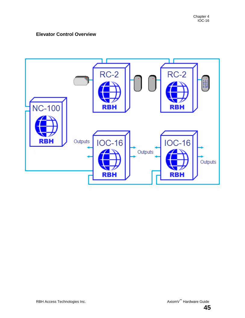
Elevator Control
AxiomV™
provides extensive elevator access control capability. A standard
reader or keypad is mounted in the elevator cabin(s). Upon presentation of a
valid code by a user, the system enables all floors that the user is authorized to
access. The user access level determines the floors and time periods during
which access is allowed. Turning on a relay output on the IOC-16 controller
enables floor access. The relay outputs are wired to the elevator control
interface board provided by the Elevator Company. A single IOC-16 controls up
to sixteen floors and up to sixteen IOC-16s can be connected to a single NC-100
controller.
A single input on the RC-2 can be configured as a floor reset input for each
elevator cabin. This input is connected to an output from the elevator that trips
when a floor is selected. All floors currently enabled will be disabled when this
input trips. This feature increases the security of the elevator control, as the
possibility of a second unauthorized person pressing a button from the previous
person‟s selection is eliminated. As soon as the first person selects a floor, all
other floors selections are canceled.
Chapter 4 IOC-16
RBH Access Technologies Inc. AxiomV™
Hardware Guide
45
Elevator Control Overview
Chapter 4 IOC-16
AxiomV™
Hardware Guide RBH Access Technologies Inc.
46
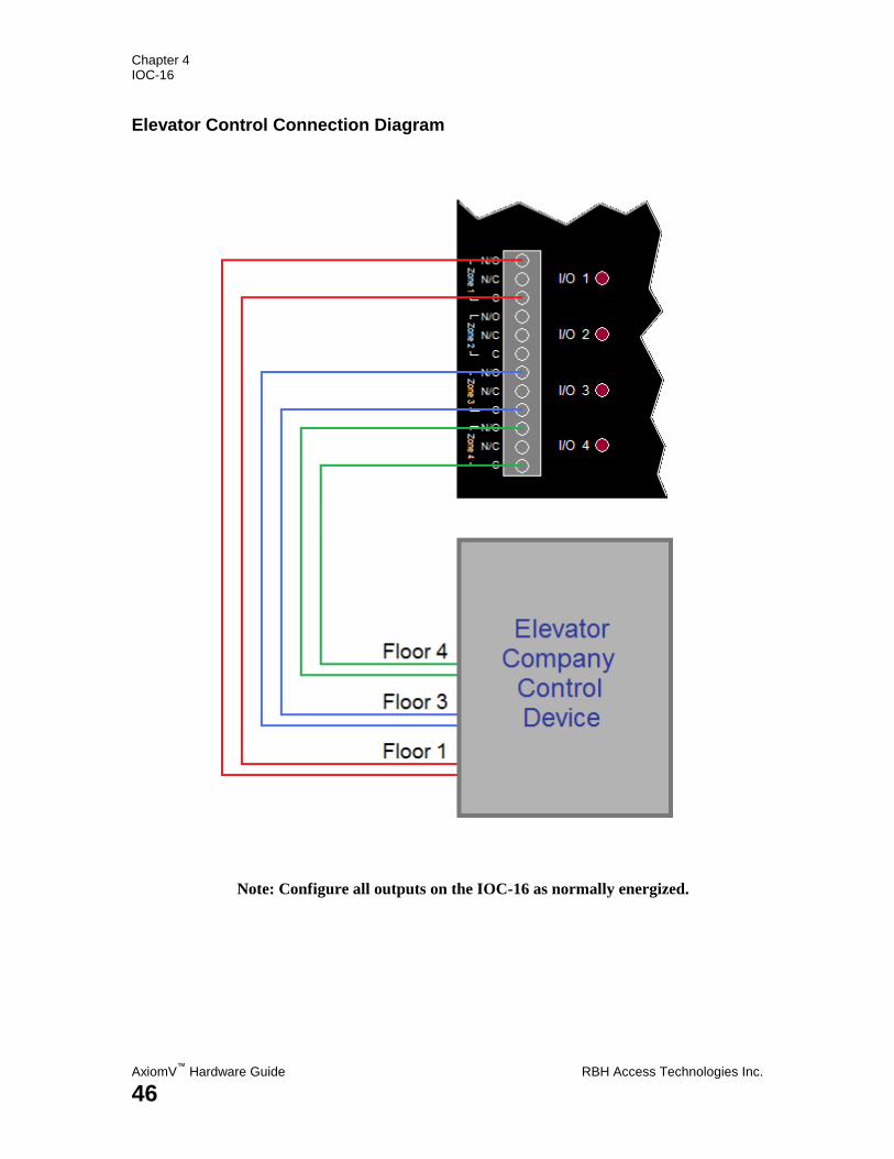
Elevator Control Connection Diagram
Note: Configure all outputs on the IOC-16 as normally energized.
Chapter 4 IOC-16
RBH Access Technologies Inc. AxiomV™
Hardware Guide
47
C h a p t e r 5
N R C 2 0 0 0 & N U R C 2 0 0 0
Chapter 5 NRC-NURC
AxiomV™
Hardware Guide RBH Access Technologies Inc.
48
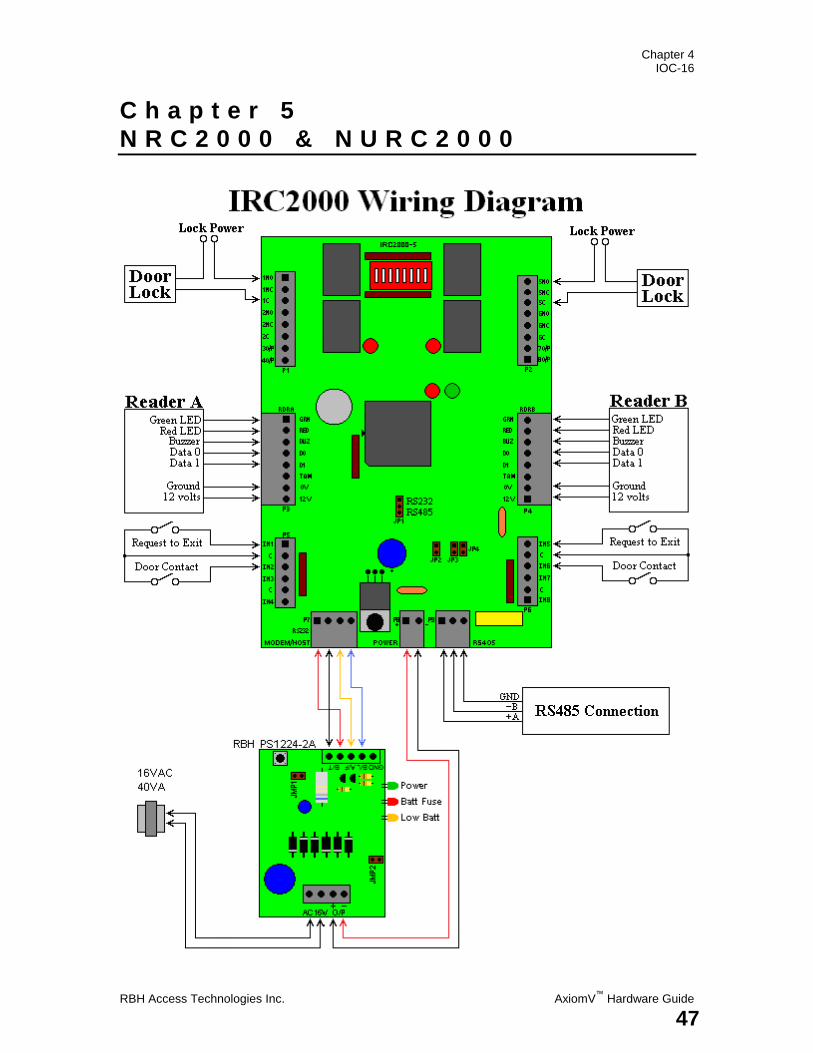
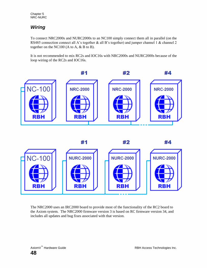
Wiring
To connect NRC2000s and NURC2000s to an NC100 simply connect them all in parallel (on the
RS485 connection connect all A‟s together & all B‟s together) and jumper channel 1 & channel 2
together on the NC100 (A to A, & B to B).
It is not recommended to mix RC2s and IOC16s with NRC2000s and NURC2000s because of the
loop wiring of the RC2s and IOC16s.
The NRC2000 uses an IRC2000 board to provide most of the functionality of the RC2 board to
the Axiom system. The NRC2000 firmware version 3 is based on RC firmware version 34, and
includes all updates and bug fixes associated with that version.
Chapter 4 IOC-16
RBH Access Technologies Inc. AxiomV™
Hardware Guide
49
Modification
Due to the lack of internal power supply and fewer I/O lines the NRC2000 does not provide the
following functionality:
1) Reader Tamper – the reader tamper inputs can be used to monitor AC failure and low
battery. Reader “A” tamper is used for AC voltage detection and should be shorted to
ground to avoid “AC FAIL” message, if the power supply modifications are not done.
Reader “B” tamper is used for battery voltage detection and should be left open to avoid
the “BATTERY FAIL” message, if the power supply modifications are not done.
2) Cabinet Tamper – always reports normal.
3) Fuse monitoring – due to lack of power supply – always normal
4) Dual RS485 redundant communications – has only a single channel so must be wired
differently!
Technical bulletin TB53 will show how to modify the IRC2000 board and how to
connect to the power supply to monitor for ‘Battery Low’ and ‘AC Failure’.
Chapter 5 NRC-NURC
AxiomV™
Hardware Guide RBH Access Technologies Inc.
50
C h a p t e r 6
P C - 1 0 0
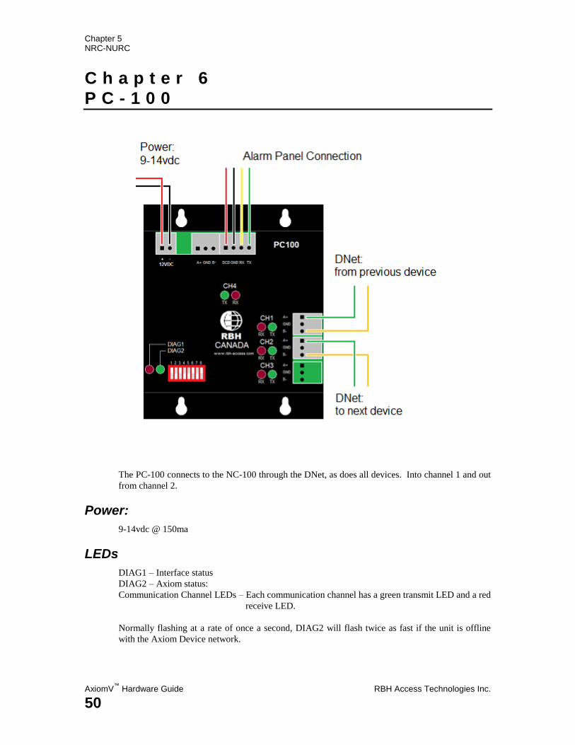
The PC-100 connects to the NC-100 through the DNet, as does all devices. Into channel 1 and out
from channel 2.
Power:
9-14vdc @ 150ma
LEDs
DIAG1 – Interface status
DIAG2 – Axiom status:
Communication Channel LEDs – Each communication channel has a green transmit LED and a red
receive LED.
Normally flashing at a rate of once a second, DIAG2 will flash twice as fast if the unit is offline
with the Axiom Device network.

RBH Access Technologies Inc. AxiomV™
Hardware Guide
51
S p e c i f i c a t i o n s

Appendix 1 Specification Sheets
AxiomV™
Hardware Guide RBH Access Technologies Inc.
52
N C - 1 0 0 S p e c i f i c a t i o n
Controller Power Requirements: 9 – 12vdc (Available from RC-2 or IOC-16)
Current Consumption: 220mA (256k RAM version)
Processor: 32 bit Motorola micro controller
Flash ROM: Download firmware upgrades from the PC to NC-100
Memory: 256k, expandable to 16M bytes of RAM
System Capacities: NC-100’s per C-NET Network Maximum of 15
RC-2 Controllers per NC-100 4 (8 card readers) IOC-16 Controllers per NC-100 16 (320 Inputs or Outputs) Cardholder No.’s per NC-100 10,000 standard, expand to 500,000 Event Log per NC-100 5,000 standard, expand to 100,000
Clock/RAM backup battery: 3v Lithium battery
C-NET (NC-100 to NC-100): Network Type ARCNET LAN Communications Speed 156k up to 2.5Mb per second Circuit Type Ring (short or open circuit protection)
D-NET (NC-100 to RC-2 and IOC-16): Network Type RS485 High Speed Network Ports Two fully supervised RS485 ports Communications speed 38400 bits/second Circuit Type Ring (short or open circuit protection)
Local PC & Remote Communications: Type RS232, TCP/IP Ethernet, RS485 4 wire Serial Port Speed Programmable, 1200 to 38,400 baud
Real Time Clock: Built-in as standard
Watch Dog Circuit: Built-in as standard
Housing dimensions: H 9.75in x W 6.875in x D 3.25in (25 x 18 x 10 cm)
Operating temperature: 0 to 70C (35 - 150F)
Operating Humidity: 20 to 80% RH (non-condensing)
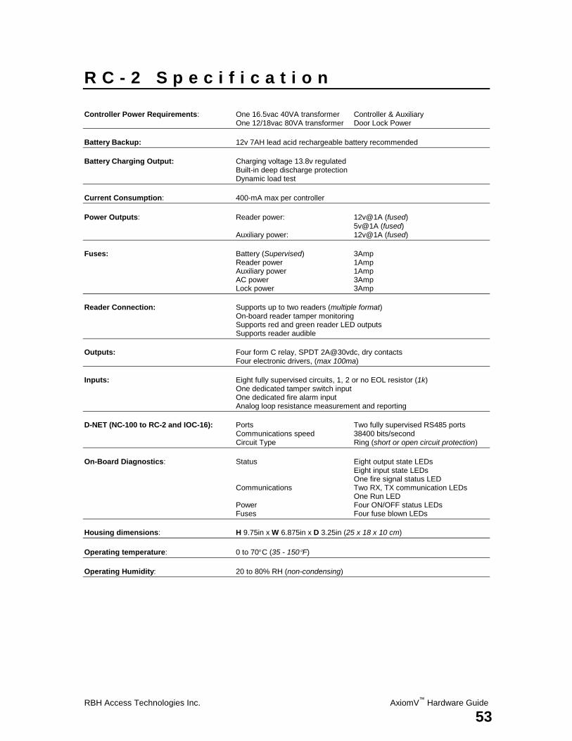
RBH Access Technologies Inc. AxiomV™
Hardware Guide
53
R C - 2 S p e c i f i c a t i o n
Controller Power Requirements: One 16.5vac 40VA transformer Controller & Auxiliary One 12/18vac 80VA transformer Door Lock Power
Battery Backup: 12v 7AH lead acid rechargeable battery recommended
Battery Charging Output: Charging voltage 13.8v regulated Built-in deep discharge protection Dynamic load test
Current Consumption: 400-mA max per controller
Power Outputs: Reader power: 12v@1A (fused)
5v@1A (fused) Auxiliary power: 12v@1A (fused)
Fuses: Battery (Supervised) 3Amp Reader power 1Amp Auxiliary power 1Amp AC power 3Amp Lock power 3Amp
Reader Connection: Supports up to two readers (multiple format) On-board reader tamper monitoring Supports red and green reader LED outputs Supports reader audible
Outputs: Four form C relay, SPDT 2A@30vdc, dry contacts
Four electronic drivers, (max 100ma)
Inputs: Eight fully supervised circuits, 1, 2 or no EOL resistor (1k) One dedicated tamper switch input One dedicated fire alarm input Analog loop resistance measurement and reporting
D-NET (NC-100 to RC-2 and IOC-16): Ports Two fully supervised RS485 ports Communications speed 38400 bits/second Circuit Type Ring (short or open circuit protection)
On-Board Diagnostics: Status Eight output state LEDs Eight input state LEDs One fire signal status LED Communications Two RX, TX communication LEDs One Run LED Power Four ON/OFF status LEDs Fuses Four fuse blown LEDs
Housing dimensions: H 9.75in x W 6.875in x D 3.25in (25 x 18 x 10 cm)
Operating temperature: 0 to 70C (35 - 150F)
Operating Humidity: 20 to 80% RH (non-condensing)
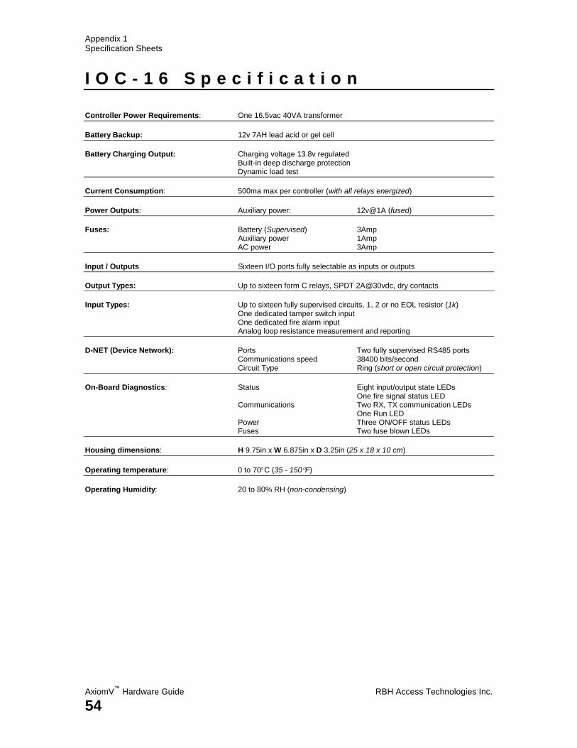
Appendix 1 Specification Sheets
AxiomV™
Hardware Guide RBH Access Technologies Inc.
54
I O C - 1 6 S p e c i f i c a t i o n
Controller Power Requirements: One 16.5vac 40VA transformer
Battery Backup: 12v 7AH lead acid or gel cell
Battery Charging Output: Charging voltage 13.8v regulated Built-in deep discharge protection Dynamic load test
Current Consumption: 500ma max per controller (with all relays energized)
Power Outputs: Auxiliary power: 12v@1A (fused)
Fuses: Battery (Supervised) 3Amp Auxiliary power 1Amp AC power 3Amp
Input / Outputs Sixteen I/O ports fully selectable as inputs or outputs
Output Types: Up to sixteen form C relays, SPDT 2A@30vdc, dry contacts
Input Types: Up to sixteen fully supervised circuits, 1, 2 or no EOL resistor (1k) One dedicated tamper switch input One dedicated fire alarm input Analog loop resistance measurement and reporting
D-NET (Device Network): Ports Two fully supervised RS485 ports Communications speed 38400 bits/second Circuit Type Ring (short or open circuit protection)
On-Board Diagnostics: Status Eight input/output state LEDs One fire signal status LED Communications Two RX, TX communication LEDs One Run LED Power Three ON/OFF status LEDs Fuses Two fuse blown LEDs
Housing dimensions: H 9.75in x W 6.875in x D 3.25in (25 x 18 x 10 cm)
Operating temperature: 0 to 70C (35 - 150F)
Operating Humidity: 20 to 80% RH (non-condensing)
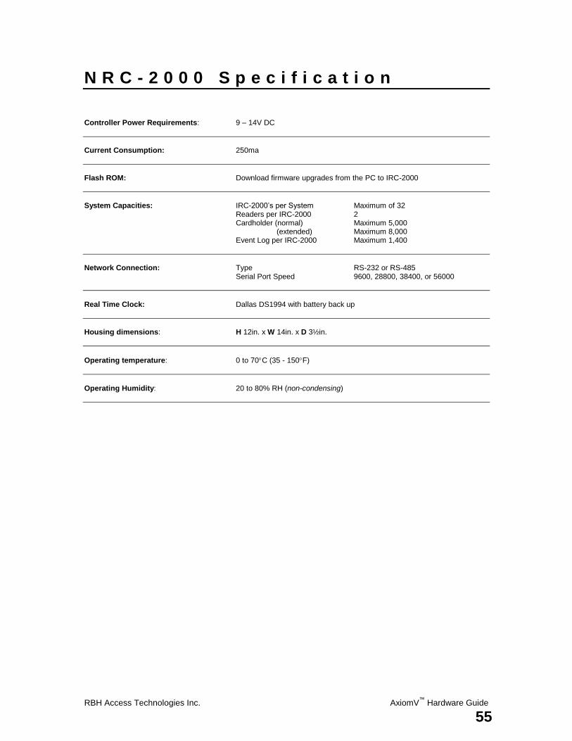
RBH Access Technologies Inc. AxiomV™
Hardware Guide
55
N R C - 2 0 0 0 S p e c i f i c a t i o n
Controller Power Requirements: 9 – 14V DC
Current Consumption: 250ma
Flash ROM: Download firmware upgrades from the PC to IRC-2000
System Capacities: IRC-2000’s per System Maximum of 32 Readers per IRC-2000 2 Cardholder (normal) Maximum 5,000 (extended) Maximum 8,000 Event Log per IRC-2000 Maximum 1,400
Network Connection: Type RS-232 or RS-485 Serial Port Speed 9600, 28800, 38400, or 56000
Real Time Clock: Dallas DS1994 with battery back up
Housing dimensions: H 12in. x W 14in. x D 3½in.
Operating temperature: 0 to 70C (35 - 150F)
Operating Humidity: 20 to 80% RH (non-condensing)

Appendix 1 Specification Sheets
AxiomV™
Hardware Guide RBH Access Technologies Inc.
56
N U R C - 2 0 0 0 S p e c i f i c a t i o n
Controller Power Requirements: 9 – 14V DC
Current Consumption: 200ma
Flash ROM: Download firmware upgrades from the PC to URC-2000.
System Capacities: URC-2000’s per System Maximum of 32 Readers per URC-2000 2 Cardholder Maximum 3,000 Event Log per URC-2000 Maximum 1,400
Network Connection: Type RS-485 Serial Port Speed 9600, 28800, 38400, or 56000
Real Time Clock: Dallas DS1994 with battery back up
Board dimensions: H 3in. x W 6½in.
Operating temperature: 0 to 70C (35 - 150F)
Operating Humidity: 20 to 80% RH (non-condensing)
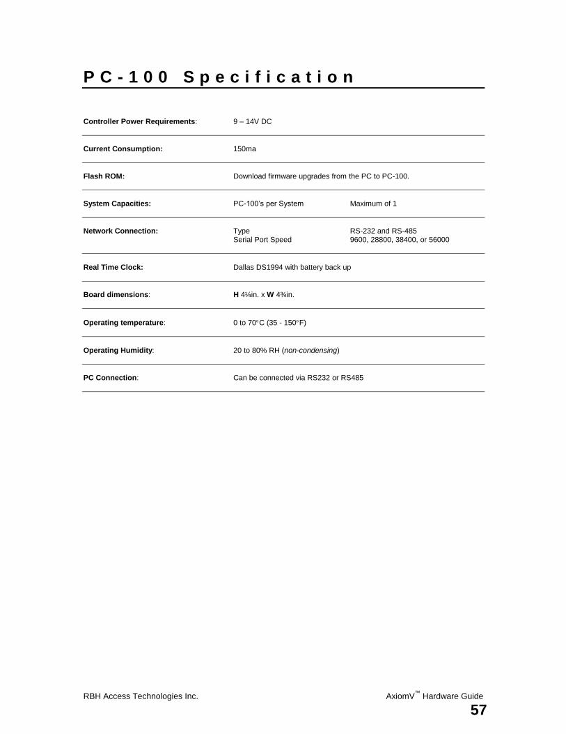
RBH Access Technologies Inc. AxiomV™
Hardware Guide
57
P C - 1 0 0 S p e c i f i c a t i o n
Controller Power Requirements: 9 – 14V DC
Current Consumption: 150ma
Flash ROM: Download firmware upgrades from the PC to PC-100.
System Capacities: PC-100’s per System Maximum of 1
Network Connection: Type RS-232 and RS-485 Serial Port Speed 9600, 28800, 38400, or 56000
Real Time Clock: Dallas DS1994 with battery back up
Board dimensions: H 4¼in. x W 4¾in.
Operating temperature: 0 to 70C (35 - 150F)
Operating Humidity: 20 to 80% RH (non-condensing)
PC Connection: Can be connected via RS232 or RS485
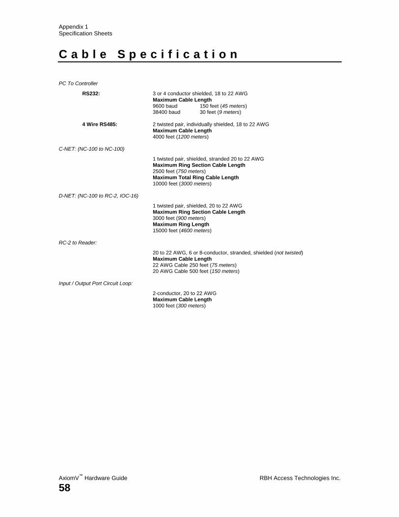
Appendix 1 Specification Sheets
AxiomV™
Hardware Guide RBH Access Technologies Inc.
58
C a b l e S p e c i f i c a t i o n
PC To Controller
RS232: 3 or 4 conductor shielded, 18 to 22 AWG
Maximum Cable Length
9600 baud 150 feet (45 meters) 38400 baud 30 feet (9 meters)
4 Wire RS485: 2 twisted pair, individually shielded, 18 to 22 AWG
Maximum Cable Length
4000 feet (1200 meters) C-NET: (NC-100 to NC-100)
1 twisted pair, shielded, stranded 20 to 22 AWG
Maximum Ring Section Cable Length
2500 feet (750 meters)
Maximum Total Ring Cable Length
10000 feet (3000 meters)
D-NET: (NC-100 to RC-2, IOC-16)
1 twisted pair, shielded, 20 to 22 AWG
Maximum Ring Section Cable Length
3000 feet (900 meters)
Maximum Ring Length
15000 feet (4600 meters)
RC-2 to Reader:
20 to 22 AWG, 6 or 8-conductor, stranded, shielded (not twisted)
Maximum Cable Length
22 AWG Cable 250 feet (75 meters) 20 AWG Cable 500 feet (150 meters)
Input / Output Port Circuit Loop:
2-conductor, 20 to 22 AWG
Maximum Cable Length
1000 feet (300 meters)
Index
RBH Access Technologies Inc. AxiomV™
Hardware Guide
59
I n d e x
AA Access Denied --------------------------------------- 33
Access Granted -------------------------------------- 33
Access Point Operating Modes ------------------ 33
Alarm Shunt ------------------------------------------ 32
Alarm Shunt Output - Connection Diagram --- 32
Auxiliary Output -------------------------------------- 6
BB Backup Battery
IOC16 ---------------------------------------------- 39
RC2 ------------------------------------------------- 21
Battery Test
IOC16 ---------------------------------------------- 41
RC2 ------------------------------------------------- 23
CC Clearing NC-100 Memory ------------------------ 17
C-Net -------------------------------------------------- 11
Connection Diagram ---------------------------- 13
Maximum Cable Length ------------------------ 13
Connection Details
IOC16 ---------------------------------------------- 39
NC100 ------------------------------------------------ 5
RC2 ------------------------------------------------- 20
Connection Diagram
C-Net ----------------------------------------------- 13
D-Net ----------------------------------------------- 15
Door Contact -------------------------------------- 24
Door Held Open ---------------------------------- 31
Door Strike ---------------------------------------- 30
Electronic Output -------------------------------- 28
Elevator Control ---------------------------------- 46
Magnetic Lock ------------------------------------ 29
RC2 to 12 volt Keypad -------------------------- 37
RC2 to 12 volt Reader -------------------------- 35
RC2 to 24 volt Reader -------------------------- 36
RC2 to 5 volt Reader ---------------------------- 34
Controller Network --------------------------------- 11
DD Default Output Operation ------------------------- 29
Device Network ------------------------------------- 14
Diagnostic LEDs ------------------------------------ 13
DIP Switch Settings
IOC16 ---------------------------------------------- 40
NC100 ----------------------------------------------- 6
RC2 ------------------------------------------------- 22
D-Net -------------------------------------------------- 14
Connection Diagram ---------------------------- 15
Maximum Cable Length ----------------------- 16
Termination --------------------------------------- 16
Door Contact ---------------------------------------- 24
Connection Diagram ---------------------------- 24
Door Held Open ------------------------------------ 31
Door Held Open Alarm --------------------------- 33
Connection Diagram ---------------------------- 31
Door Held Open Warning ------------------------ 33
Door Strike - Connection Diagram ------------- 30
EE Electronic Output - Connection Diagram ------ 28
Elevator Control ------------------------------------ 44
Connection Diagram ---------------------------- 46
Elevator Control Overview ----------------------- 45
FF Fire Release Input
IOC16 ---------------------------------------------- 39
RC2 ------------------------------------------------- 21
Forced / Tamper ------------------------------------ 30
HH High Security Mode-------------------------------- 33
II Input / Output Selection --------------------------- 42
Input Circuit Types --------------------------------- 25
Input/Output Controller --------------------------- 38
Inputs
IOC16 ---------------------------------------------- 43
RC2 ------------------------------------------------- 24
Interface Wiring
RS232 ------------------------------------------------ 9
RS485 ---------------------------------------------- 10
Introducing AxiomV --------------------------------- 1
IOC16 ------------------------------------------------- 38
Backup Battery ----------------------------------- 39
Battery Test --------------------------------------- 41
Connection Details ------------------------------ 39
DIP Switch Settings ----------------------------- 40
Appendix 1 Specification Sheets
AxiomV™
Hardware Guide RBH Access Technologies Inc.
60
Fire Release Input -------------------------------- 39
Inputs ----------------------------------------------- 43
Outputs --------------------------------------------- 43
Silkscreen Legend ------------------------------- 38
Status LED's -------------------------------------- 41
Switching Inductive Devices ------------------ 44
Tamper --------------------------------------------- 39
KK Keypad / Reader Combination ------------------- 33
LL Lock Output ------------------------------------------ 29
Lockout Alarm -------------------------------------- 33
MM Magnetic Lock - Connection Diagram --------- 29
Master Controller ------------------------------------- 7
Maximum Cable Length
C-NET ---------------------------------------------- 13
D-NET---------------------------------------------- 16
Reader ---------------------------------------------- 34
Modification
NRC2000 ------------------------------------------ 49
NN NC100 --------------------------------------------------- 4
Connection Details -------------------------------- 5
DIP Switch Settings ------------------------------- 6
Panel Reset ------------------------------------------ 8
Silkscreen Legend --------------------------------- 5
Status LED's -------------------------------------- 13
NC-100 Networks ----------------------------------- 11
Network Controller ----------------------------------- 4
NRC2000 --------------------------------------------- 47
Wiring ---------------------------------------------- 48
NURC2000 ------------------------------------------- 47
Wiring ---------------------------------------------- 48
OO Outputs
IOC16 ---------------------------------------------- 43
RC2 ------------------------------------------------- 28
PP Panel Reset --------------------------------------------- 8
PC Connection----------------------------------------- 8
PC-100 ------------------------------------------------ 50
Specification -------------------------------------- 57
Port Baud Rate Selection --------------------------- 8
RR RC2 ---------------------------------------------------- 18
Backup Battery ----------------------------------- 21
Battery Test --------------------------------------- 23
Connection Details ------------------------------ 20
DIP Switch Settings ----------------------------- 22
Fire Release Input ------------------------------- 21
Inputs ----------------------------------------------- 24
Outputs -------------------------------------------- 28
Silkscreen Legend ------------------------------- 19
Status LED's -------------------------------------- 22
Switching Inductive Devices ------------------ 28
Tamper --------------------------------------------- 21
Reader
Maximum Cable Length ----------------------- 34
Reader - Connection Diagrams ------------------ 34
Reader Controller----------------------------------- 18
Request To Exit ------------------------------------- 24
RS232
Connection ------------------------------------------ 9
Interface Wiring ----------------------------------- 9
RS485
Connection ---------------------------------------- 10
Interface Wiring --------------------------------- 10
RTE --------------------------------------------------- 24
SS Silkscreen Legend
IOC16 ---------------------------------------------- 38
NC100 ----------------------------------------------- 5
RC2 ------------------------------------------------- 19
Slave Controller -------------------------------------- 7
Specification
Cable ----------------------------------------------- 58
IOC16 ---------------------------------------------- 54
NC100 --------------------------------------------- 52
NRC-2000 ----------------------------------------- 55
NURC-2000 -------------------------------------- 56
PC-100 --------------------------------------------- 57
RC2 ------------------------------------------------- 53
Status LED's
IOC16 ---------------------------------------------- 41
NC100 --------------------------------------------- 13
RC2 ------------------------------------------------- 22
Switching Inductive Devices
IOC16 ---------------------------------------------- 44
Index
RBH Access Technologies Inc. AxiomV™
Hardware Guide
61
RC2 ------------------------------------------------- 28
System Diagram --------------------------------------- 3
TT Tamper ------------------------------------------------ 33
IOC16 ---------------------------------------------- 39
RC2 ------------------------------------------------- 21
Termination ------------------------------------------ 16
Two Person Mode ---------------------------------- 33
UU Unlocked Mode ------------------------------------- 33
WW Wiring
NRC2000/ NURC2000 ------------------------- 48