military antenna solutions - short, medium & long … n t e nnas. com an amphenol company...
TRANSCRIPT
w w w . c s a n t e n n a s . c o m
An Amphenol CompanyC&S ANTENNAS
Lightweight Manportable HF Broadband Antennas
FANLITE™
Military Antenna Solutions
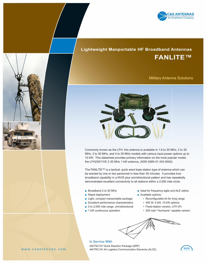
Commonly known as the LFH, this antenna is available in 1.6 to 30 MHz, 2 to 30 MHz, 3 to 30 MHz, and 4 to 30 MHz models with various input power options up to 10 kW. This datasheet provides primary information on the most popular model, the LFH230/1/VE 2 30 MHz 1 kW antenna, (NSN 5985-01-342-9592).
The FANLITE™ is a tactical, quick erect base station type of antenna which can be erected by one or two personnel in less than 30 minutes. It provides true broadband capability in a NVIS plus omnidirectional pattern and has repeatedly demonstrated excellent connectivity to all stations within a 2,000 mile circle.
■ Broadband 2 to 30 MHz■ Rapid deployment■ Light, compact manportable package■ Excellent performance characteristics■ 0 to 2,000 mile range, omnidirectional■ 1 kW continuous operation
In Service WithAN/TSC107 Quick Reaction Package (QRP)AN/TRC181 Air Logistics Communication Elements (ALCE)
■ Ideal for frequency-agile and ALE radios■ Available options:
• Reconfi gurable kit for long range• 400 W, 4 kW, 10 kW options• Fixed-station version, LFH (P)• 200 mph “Hurricane” capable version
NVISNVIS
FANLITE™ Manportable Theater Range HF Antenna
2w w w . c s a n t e n n a s . c o m
tel: +1.828.324.2454 | fax: +1.828.324.2072
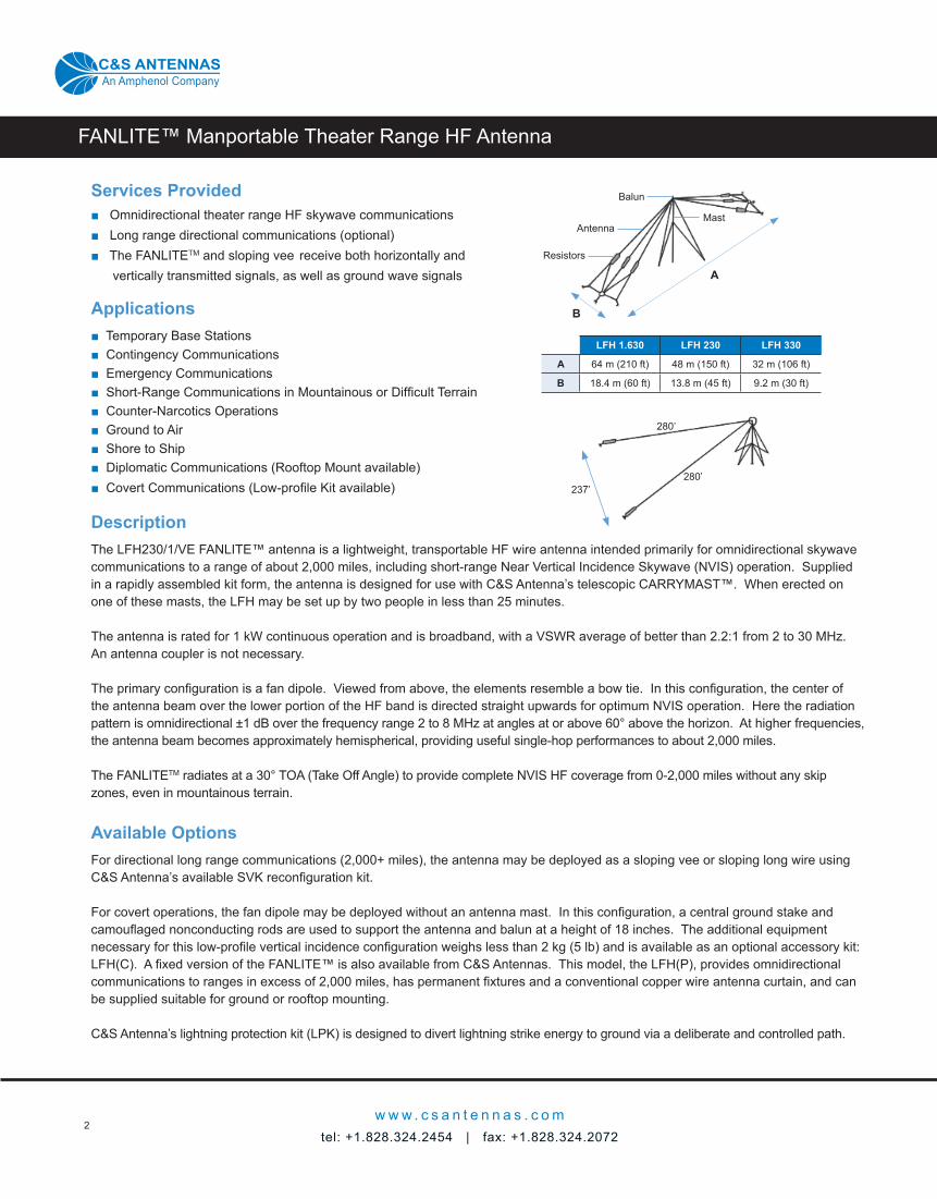
Services Provided■ Omnidirectional theater range HF skywave communications■ Long range directional communications (optional) ■ The FANLITETM and sloping vee receive both horizontally and vertically transmitted signals, as well as ground wave signals
Applications■ Temporary Base Stations■ Contingency Communications■ Emergency Communications■ Short-Range Communications in Mountainous or Diffi cult Terrain■ Counter-Narcotics Operations■ Ground to Air■ Shore to Ship■ Diplomatic Communications (Rooftop Mount available)■ Covert Communications (Low-profi le Kit available)
DescriptionThe LFH230/1/VE FANLITE™ antenna is a lightweight, transportable HF wire antenna intended primarily for omnidirectional skywave communications to a range of about 2,000 miles, including short-range Near Vertical Incidence Skywave (NVIS) operation. Supplied in a rapidly assembled kit form, the antenna is designed for use with C&S Antenna’s telescopic CARRYMAST™. When erected on one of these masts, the LFH may be set up by two people in less than 25 minutes.
The antenna is rated for 1 kW continuous operation and is broadband, with a VSWR average of better than 2.2:1 from 2 to 30 MHz. An antenna coupler is not necessary.
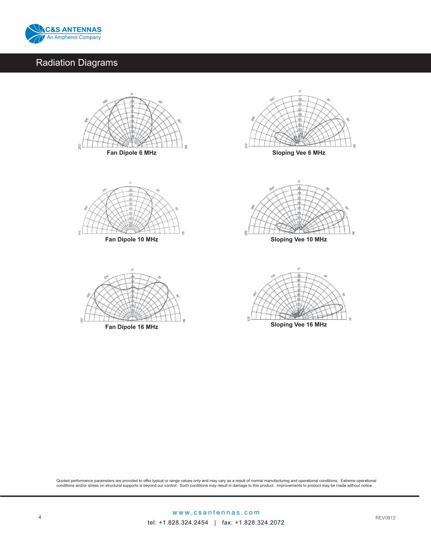
The primary confi guration is a fan dipole. Viewed from above, the elements resemble a bow tie. In this confi guration, the center of the antenna beam over the lower portion of the HF band is directed straight upwards for optimum NVIS operation. Here the radiation pattern is omnidirectional ±1 dB over the frequency range 2 to 8 MHz at angles at or above 60° above the horizon. At higher frequencies, the antenna beam becomes approximately hemispherical, providing useful single-hop performances to about 2,000 miles.
The FANLITETM radiates at a 30° TOA (Take Off Angle) to provide complete NVIS HF coverage from 0-2,000 miles without any skip zones, even in mountainous terrain.
Available OptionsFor directional long range communications (2,000+ miles), the antenna may be deployed as a sloping vee or sloping long wire using C&S Antenna’s available SVK reconfi guration kit.
For covert operations, the fan dipole may be deployed without an antenna mast. In this confi guration, a central ground stake and camoufl aged nonconducting rods are used to support the antenna and balun at a height of 18 inches. The additional equipment necessary for this low-profi le vertical incidence confi guration weighs less than 2 kg (5 lb) and is available as an optional accessory kit: LFH(C). A fi xed version of the FANLITE™ is also available from C&S Antennas. This model, the LFH(P), provides omnidirectional communications to ranges in excess of 2,000 miles, has permanent fi xtures and a conventional copper wire antenna curtain, and can be supplied suitable for ground or rooftop mounting.
C&S Antenna’s lightning protection kit (LPK) is designed to divert lightning strike energy to ground via a deliberate and controlled path.
LFH 1.630 LFH 230 LFH 330
A 64 m (210 ft) 48 m (150 ft) 32 m (106 ft)
B 18.4 m (60 ft) 13.8 m (45 ft) 9.2 m (30 ft)
Resistors
A
B
Antenna
Balun
Mast
280’
280’237’
An Amphenol CompanyC&S ANTENNAS
Quoted performance parameters are provided to offer typical or range values only and may vary as a result of normal manufacturing and operational conditions. Extreme operational conditions and/or stress on structural supports is beyond our control. Such conditions may result in damage to this product. Improvements to product may be made without notice.
Antenna Specifi cations
w w w . c s a n t e n n a s . c o mtel: +1.828.324.2454 | fax: +1.828.324.2072
3
ELECTRICAL
Frequency Range: 2 to 30 MHz
Input Impedance: 50 ohms
VSWR: < 2.2:1 across band
Power Rating: 1 kW continuous
Polarization: Vertical (NVIS)
Receive (Rx): Horizontally & vertically transmitted signals as well as ground wave
Gain: refer to Typical Power Gain Table below
MECHANICAL
Weight: 19 kg (42 lb)
Stowed Size: 0.25 x 0.25 x 0.6 m (10 x 10 x 24 in)
Deployed Size: 48 x 13.8 m (150 x 45 ft)
Erection Time: 25 minutes (2 people) with C&S Antennas’ CARRYMAST™ telescopic mast
Max Wind Speed: 145 km/hr (90 mph)
Max Wind Speed, Permanent Version: LFHP230/HD, LFHP230/SHD
322 km/hr (200 mph)
Temperature Range: -40° to +160° F
Antenna Elements: Kevlar & copper
Fittings: Stainless steel
ELECTRICAL
Frequency Range: 2 to 30 MHz (8 to 26 MHz optimum)
Input Impedance: 50 ohms
VSWR: < 2.2:1 across band
Power Rating: 1 kW continuous
Polarization: Horizontal
Receive (Rx): Horizontally & vertically transmitted signals as well as ground wave
Gain: refer to Typical Power Gain Table below
MECHANICAL
Weight: 19 kg (42 lb)
Stowed Size: 0.25 x 0.25 x 0.6 m (10 x 10 x 24 in)
Deployed Size: 86 x 76 m (280 x 250 ft)
Erection Time: 25 minutes (2 people) with C&S Antennas’ CARRYMAST™ telescopic mast
Max Wind Speed: 145 km/hr (90 mph)
Max Wind Speed, Permanent Version: LFHP230/HD, LFHP230/SHD
322 km/hr (200 mph)
Temperature Range: -40° to +160° F
Antenna Elements: Kevlar & copper
Fittings: Stainless steel
LFH Fan Dipole Confi guration LFH Sloping Vee Confi guration
OptionsLFH 400 W balun
Mast C&S Antenna’s CARRYMAST™ CTM9, CTM10, CTM12 or CTM15
LPK Lightning Protection Kit
LFH(P) Permanent Site Version (rooftop mounting details on request)
LFH(C) Covert Operations Kit (details on request)
SVK Kit to reconfi gure to sloping vee or sloping long wire
An Amphenol CompanyC&S ANTENNAS
Typical Power Gain (dBi)Frequency (MHz) 2 3 4 6 8 10 12 16 20 30 40
Fan Dipole -2.5 -2.0 -1.0 0 +2.0 +2.5 +3.0 +3.0 +2.5 +2.0 -
Sloping Vee 280’ -9.4 -6.5 -1.8 +1.7 +4.6 +6.4 +7.5 +8.2 +8.5 +9.6 +10.0
Notes:1. The sloping vee data refers to an antenna with 86 m (280 ft) leg lengths.2. Power gain for sloping vee assumes apex angle between legs is 50° for frequencies between 24 MHz and 35° for frequencies above 24 MHz. This equates to leg spacings of 73 m (237 ft) and 53 m (172 ft) respectively.3. Gains are stated for antennas supported on a 15 m (49.2 ft) mast over average ground. (Conductivity 10 mS/m; relative permittivity 10).
Quoted performance parameters are provided to offer typical or range values only and may vary as a result of normal manufacturing and operational conditions. Extreme operational conditions and/or stress on structural supports is beyond our control. Such conditions may result in damage to this product. Improvements to product may be made without notice.
Radiation Diagrams
REV0812
An Amphenol CompanyC&S ANTENNAS
4w w w . c s a n t e n n a s . c o m
tel: +1.828.324.2454 | fax: +1.828.324.2072
Fan Dipole 6 MHz
Fan Dipole 10 MHz
Fan Dipole 16 MHz
Sloping Vee 6 MHz
Sloping Vee 10 MHz
Sloping Vee 16 MHz