ov us catalog r2-0801:catalog with no price catalogs/ov_us_productrange_r...fuel oil line components...
TRANSCRIPT

Product Page
General notes 2
Non-electric thermostatic actuators for zone/radiator valves 3
Electrothermal actuators 5
Accessories - Thermostats 6
Radiator/Zone valves 7
Radiator valves ”Series E” 10Service valves ”Combi E”
Valve inserts 11”Demo-Bloc”
Radiator service valves 12”Combi 2”, ”Combi 4” and ”Multiflex” fittings
Three-way valves and actuators 13
Floor heat manifolds 14
”Unibox” 15Pressure actuated bypass valvesAutomatic airvents
Fuel Oil Line Components 16
Regumat Boiler Valves 17
Solar Products 18 Balancing Valves 19
PEX Pipe 20
Warranty 21 Terms and Conditions 22
1
Content
2
General notes
Notes
Oventrop’s Standard Terms andConditions of Sale and Warranty apply.
If not stated otherwise, all hydronic partsin this list are suitable for hot water with
an operating temperature of up to 240 °Fand an operating pressure of up to 50 psi.
This list reflects some 100 itemsfrom the Oventrop product line of
approximately 4.000 items.We will be updating our product range for
the USA on a regular basis.
For information on additional items,please visit our websitewww.oventrop-na.com
Upon request we will gladly investigateavailability and pricing of items not
mentioned in this book.

3
Non-electric thermostaticactuators for zone/radiator valves
Thermostat ”Uni XH”with liquid sensor
white model (100) M 30 x 1,5 101 13 65
same with remote sensor
capillary 6 1/2 feet (10) M 30 x 1,5 101 15 65 capillary 16 feet (10) M 30 x 1,5 101 15 66
Thermostat ”Uni XD”with liquid sensor
white model (50) squeeze 101 13 75
same with remote sensor
capillary 6 1/2 feet (10) squeeze 101 15 75
Thermostat ”Uni LH”with liquid sensor
chrome plated modelwith two piece trimring to hide nickelplated lock nut (10) M 30 x 1,5 101 14 69
Thermostat ”Vindo”with liquid sensor (10) M 30 x 1,5 101 30 65
squeeze 101 30 75
Thermostat ”Uni DH”with wax sensorcompact model
white model (100) M 30 x 1,5 101 10 65
samewith remote sensor
capillary 6 1/2 feet (10) M 30 x 1,5 101 11 65
These actuators provide an elegantly simplemeans of controlling space temperature byadjusting the flow rate through the heater.Modulating (not on-off) control that enablesautomatic matching of heat loss.
Temperature setting may be limited or locked.Memory disc to mark favorite setpoint”0” setting = positive ”off””X” setting = freeze protectionTemperature range 42° . . . 84°FMarkings on the dial 0X 1-5
”XD” thermostats can be fitted withoutadapter to Danfoss valves, series RA(squeeze connection) and Buderus radiatorswith integrated valve assembly.
Temperature setting may be limited or locked.Memory disc to mark favorite setpoint”0” setting = positive ”off””X” setting = freeze protectionTemperature range 42° . . . 84°F
Same models ”Uni LD” with ”squeeze” connection upon request.Vindo is a new compact model for 2007.
Temperature setting may be limited or locked.”0” setting = positive ”off””X” setting = freeze protectionTemperature range 42° . . . 84°F
No ”positive off” setting
Most actuators can be supplied with 2 available connections:
1. Threaded M 30 x 1,5 for use with Oventrop valves
2. ”Squeeze” type for use with Danfoss valves
Box Item qty. Thread Item no. List Price Information

4
Non-electric thermostaticactuators for zone/radiator valves
Thermostat with remotecontrol ”Uni LH”
white model
capillary 6 1/2 feet (25) M 30 x 1,5 101 22 95
capillary 16 feet (25) M 30 x 1,5 101 22 96
capillary 33 feet (10) M 30 x 1,5 101 22 97
white model with additional remote sensor
capillary 6 1/2 feet (10) M 30 x 1,5 101 23 95
capillary 16 feet (10) M 30 x 1,5 101 23 96
Thermostat with remotecontrol ”Uni LD”
white model
capillary 6 1/2 feet (10) squeeze 101 22 75
Wall mounted remote control(for radiators, baseboard, floor heating).
Temperature setting may be limited or lockedby means of hidden set tabs.”0” setting = positive ”off””X” setting = freeze protectionTemperature range 42° . . . 84°F
Same features as above, plus a remotesensor.
”LD” thermostats can be fitted withoutadapter to Danfoss valves, series RA(squeeze connection) and Buderus radiatorswith integrated valve assembly.
Box Item qty. Thread Item no. List Price Information

5
Electrothermal actuators
Electrothermal actuators
Electrothermal actuator (LH)connection thread M 30 x 1,5”compact design”normally closed, 24 V, 2 Wattwith end switch (100) 101 24 96
Electrothermal actuatorconnection thread M 30 x 1,5normally closed, 24 V 101 24 86
Electrothermal actuators control the roomtemperature and can be used withconventional radiators, manifolds forunderfloor heating systems, radiant andchilled ceiling systems and fan coil units.The actuators are protected againstovervoltage.
For floor heat manifolds and zone valves.Slow acting to prevent water hammer.Cable 32" (4 wires).End switch can be used to start a pump through a line voltage relay.
For mixing and diverting valves.Can be converted to normally open.Cable 40" (2 wires).
Box Item qty. Item no. List Price Information
6
Accessories - Thermostats
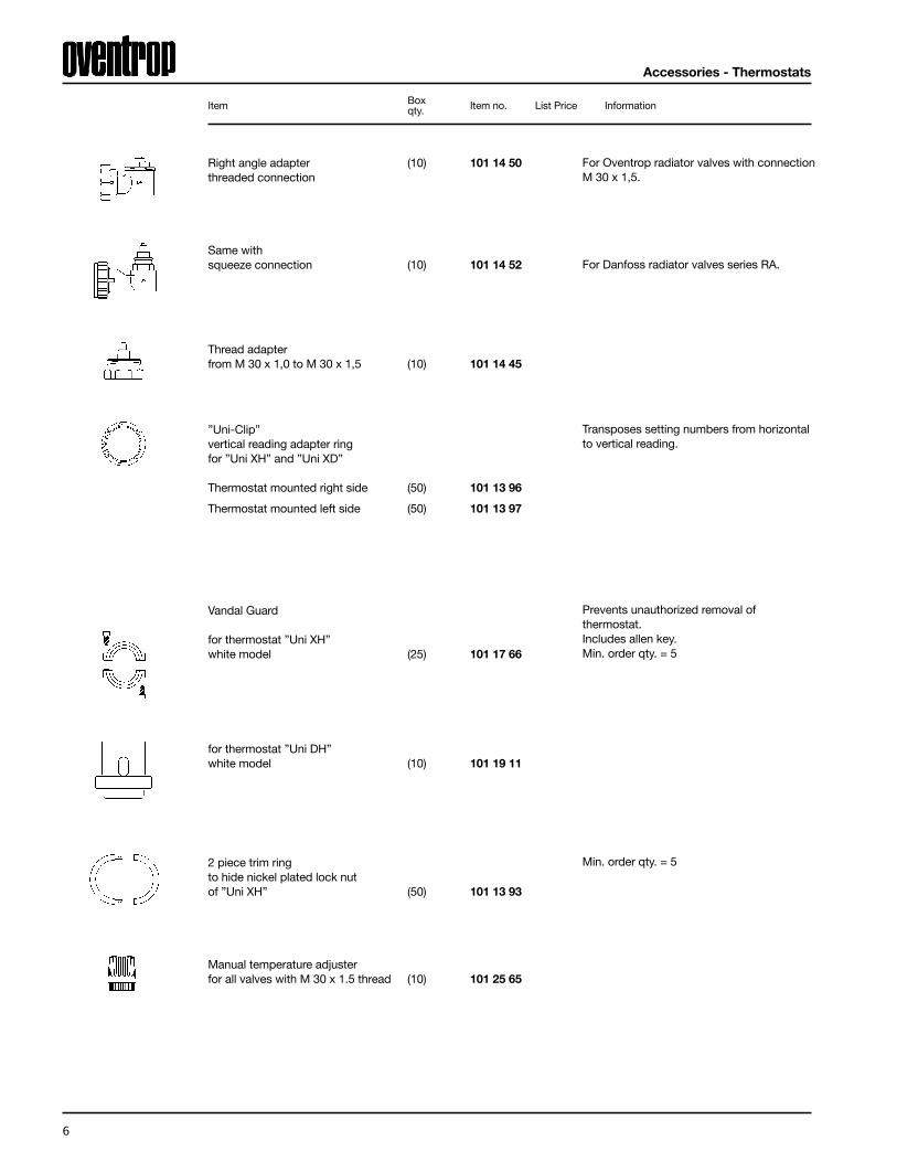
Right angle adapter (10) 101 14 50 threaded connection
Same with squeeze connection (10) 101 14 52
Thread adapterfrom M 30 x 1,0 to M 30 x 1,5 (10) 101 14 45
”Uni-Clip”vertical reading adapter ringfor ”Uni XH” and ”Uni XD”
Thermostat mounted right side (50) 101 13 96
Thermostat mounted left side (50) 101 13 97
Vandal Guard
for thermostat ”Uni XH”white model (25) 101 17 66
for thermostat ”Uni DH”white model (10) 101 19 11
2 piece trim ringto hide nickel plated lock nutof ”Uni XH” (50) 101 13 93
Manual temperature adjusterfor all valves with M 30 x 1.5 thread (10) 101 25 65
For Oventrop radiator valves with connectionM 30 x 1,5.
For Danfoss radiator valves series RA.
Transposes setting numbers from horizontalto vertical reading.
Prevents unauthorized removal ofthermostat.Includes allen key.Min. order qty. = 5
Box Item qty. Item no. List Price Information
Min. order qty. = 5

7
Zone/radiator valvesOne pipe radiator valves “Tauch-Rohr”
Zone/radiator valveswith M 30 x 1,5 threadedactuator connection,brass, nickel plated
”Series AZ” (for hot water)
Angle pattern valve NPT/NPT
1/2" (25) 188 90 04 3/4" (25) 188 90 06 1" (10) 188 90 08 1 1/4" (10) 188 90 10
Straight pattern valve NPT/NPT
1/2" (25) 188 91 04 3/4" (25) 188 91 06 1" (10) 188 91 08 1 1/4" (10) 188 91 10
Reversed angle pattern valve NPT/NPT
1/2" (25) 188 92 04 3/4" (25) 188 92 06
Double angle pattern valve NPT/NPT
1/2" left hand side connection (25) 169 40 62
1/2" right hand side connection (25) 169 40 63
These valves can be used with 4 types ofactuators:
1. Manual adjuster (included)2. Thermostatic (non-electric)3. Thermostatic remote capillary (non-electric)4. 24 V electric for on/off control
All valve inserts are replaceable underworking conditions by means of the specialtool ”Demo-Bloc”.
System does not needto be drained!
Box Item qty. Thread Item no. List Price Information
Technical data, refer to page 17+18
The constant bypass of the one pipe radiator injection valves is adjusted to a radiator flow share of 35%.The insertion tube is 6" long, has a diameter of 7⁄16" and the distance between pipe centres is 50 mm.
One pipe radiator injection valveswith constant bypass and shut off
Connections1/2" to radiator3/4" (R 20) to system
with horizontal insertion tube 118 35 61
with vertical insertion tube 118 35 71 The one pipe radiator injection valve with vertical insertion tube is especiallysuitable for towel radiators. (The technicalinstructions of the radiator manufacturers need to be observed.)

8
M 30 x 1,0 Actuator thread.
Add adapter item no. 101 14 45.
These valves can be used with 4 types of actuators:
1. Manual adjuster (included)2. Thermostatic (non-electric)3. Thermostatic remote capillary (non-electric)4. 24 V electric for on/off control
All valve inserts are replaceable under working conditions by means of the special tool ”Demo-Bloc”.
System does not needto be drained!
Angle pattern valve NPT/NPT1/2" (25) 189 90 04 3/4" (25) 189 90 06 1" (25) 189 90 08 1 1/4" (25) 189 90 10
Straight pattern valve NPT/NPT1/2" (25) 189 91 04 3/4" (25) 189 91 06 1" (25) 189 91 08 1 1/4" (25) 189 91 10
Reversed angle pattern valve NPT/NPT1/2" 189 92 04 3/4" 189 92 06
”Series S” (for low pressure steam, max. 15 psi)
Steam Radiator Valve
One-pipe steam radiator valve NPT
1/8" (25) 188 83 51
Zone/radiator valves
Box Item qty. Thread Item no. List Price Information

9
Zone/radiator valves
Zone/radiator valveswith M 30 x 1,5 threadedactuator connection,brass, nickel plated,standard AZ insert
Angle pattern valve sweat/sweat
1/2" (25) 169 44 04 3/4" (25) 169 44 06
Straight pattern valve sweat/sweat
1/2" (25) 169 44 14 3/4" (25) 169 44 16 3/4" (25) 169 44 16 ZV3/4" (25) 169 44 16 ZVO*1694416ZV inculdes (1) 1012496 Electrothermal actuator (LH)connection thread M 30 x 1,5,normally closed, 24 V, 2 Wattwith end switch. *1694416ZVO includes (1) 1012486 Electrothermal actuatorconnection thread M 30 x 1,5, normally open, 24 V.
Reversed angle pattern valve sweat/sweat1/2" 169 44 24 3/4" 169 44 26
Box Item qty. Thread Item no. List Price Information
Incl. (2) unions and sweat tails.
If ordered separately.
Sweat tailpiece for zoneradiator valves
1/2" (100) 198 76 51 3/4" 198 76 52 1" 198 76 53 1 1/4" 198 76 54
10
Radiator valves ”Series E”Service valves ”Combi E”
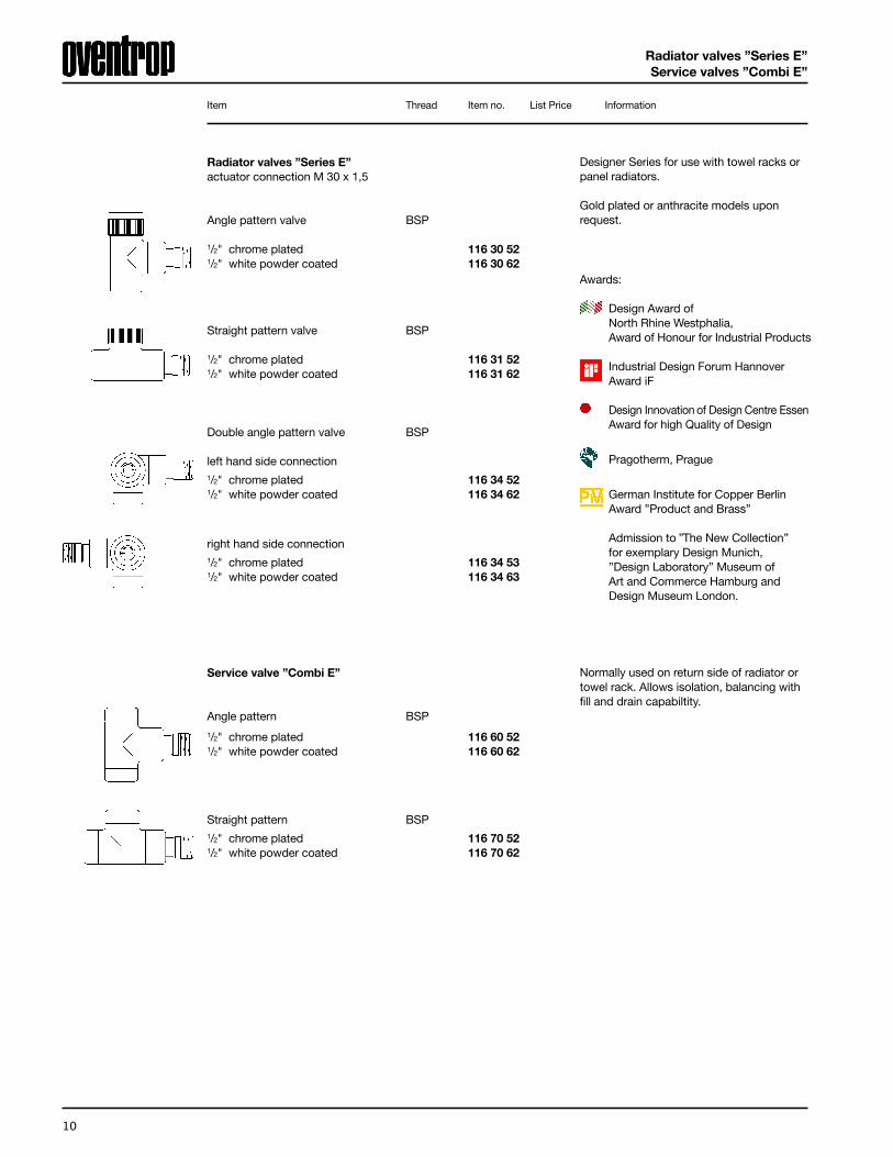
Radiator valves ”Series E”actuator connection M 30 x 1,5
Angle pattern valve BSP
1/2" chrome plated 116 30 52 1/2" white powder coated 116 30 62
Straight pattern valve BSP
1/2" chrome plated 116 31 52 1/2" white powder coated 116 31 62
Designer Series for use with towel racks orpanel radiators.
Gold plated or anthracite models uponrequest.
Awards:
Design Award ofNorth Rhine Westphalia,Award of Honour for Industrial Products
Industrial Design Forum HannoverAward iF
Design Innovation of Design Centre EssenAward for high Quality of Design
Pragotherm, Prague
German Institute for Copper BerlinAward ”Product and Brass”
Admission to ”The New Collection”for exemplary Design Munich,”Design Laboratory” Museum of Art and Commerce Hamburg and Design Museum London.
Item Thread Item no. List Price Information
Double angle pattern valve BSP
left hand side connection1/2" chrome plated 116 34 52 1/2" white powder coated 116 34 62
right hand side connection1/2" chrome plated 116 34 53 1/2" white powder coated 116 34 63
Service valve ”Combi E”
Angle pattern BSP
1/2" chrome plated 116 60 52 1/2" white powder coated 116 60 62
Straight pattern BSP1/2" chrome plated 116 70 52 1/2" white powder coated 116 70 62
Normally used on return side of radiator ortowel rack. Allows isolation, balancing withfill and drain capabiltity.

11
Valve inserts”Demo-Bloc”
Valve insertsfor all valves M 30 x 1,5(M 30 x 1,0 upm request)
Valve insert ”Series AZ” 1.28 118 70 60
Valve insert ”Series AV 6” 0.75 118 70 57 with presetting
Valve insert ”Series ADV 6” 0.75 118 60 01 ”Landlord model”
Valve insert with stainless 0.70 118 62 00 steel seat
Special valve insert 0.52 118 70 70
Valve insert ”Series KT” 0.58 114 71 69
Valve insert ”Series TM” 106 70 85 1⁄2" 1.13⁄4" 1.21" 1.311⁄4" 1.6
Gland nut 101 75 01 Set = 5 pieces
”Demo-Bloc”special tool for replacing Oventropvalve inserts under working conditionsfor both M 30 x 1,0 and M 30 x 1,5thread connections 118 80 51
Keyfor flow rate setting onAV 6 / ADV 6 inserts 118 39 61
Standard with Oventrop zone/radiator valvesM 30 x 1,5 Highest Cv.
Adjustable Cv valve insert, allows technicianto balance flow rate. Six different settings.
Same as ”Series AV 6”, but with additionalfeature that, if thermostat is removed, flowwill be restricted to 5% of normal flow.
Especially for steam installations.
Low Cv, to correct reversed supply/returnhookup.
Opens valve upon rising temperature.
Insert for pressure differential of up to 40 psi (for commercial baseboard etc.).
Wrench size 14 mmMin. order qty. = 5
Item Cv Item no. List Price Information

12
Radiator service valves”Combi 2” and ”Multiflex” fittings
Service valve ”Combi 2”balancing, shut-off
Angle pattern NPT inletnickel plated NPT tailpiece1/2" (100) 109 10 82 3/4" 109 10 83
1/2" (100) sweat/sweat 109 10 92 3/4" (25) 109 10 93
Straight pattern NPT inletnickel plated NPT tailpiece1/2" (100) 109 11 82 3/4" (25) 109 11 83
1/2" (100) sweat/sweat 109 11 92
Service valve ”Combi 4”balancing with memory position, shut-off,filling and draining
Angle pattern NPT inletnickel plated NPT tailpiece1/2" 109 06 82 3/4" 109 06 83
Straight pattern NPT inletnickel plated NPT tailpiece1/2" 109 07 82 3/4" 109 07 83
Used on the return side of radiators,baseboard or floor heat to providebalancing and shut-off capability.Use 5/32" (4 mm) allen key.
Box Item qty. Thread Item no. List Price Information
For Series Loop systems,allows setting of flow to next radiators in loop. Isolation capability.Factory Setting 35%.
”Multiflex” fittings
for Panel Radiators with Bottom Tappingsand Built-in Valve Assembly (such as Buderus, DiaNorm)
Diverter valves1/2" angle (10) 101 59 34
same, Straight 101 59 33
2-Pipe isolating valve1/2" angle (10) 101 58 14
same, Straight 101 58 13
Adapter from 1/2" female to 3/4" male (Euroconus)
(10) 102 82 53
For use with compression fittings.
”Euroconus”compression fittings for Floor Heat Manifolds”Unibox”, Panel Radiators etc.
US – PEX 3/8" (100) 164 68 49 US – PEX 1/2" (100) 164 68 50 US – PEX 5/8" (100) 164 68 51
Copper 1/2" (100) 101 68 44 Copper 1/2" (100) 101 68 64
Incl. (2) unions and sweat tails.
Incl. (2) unions and sweat tails.
13
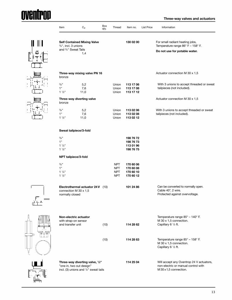
Three-way valves and actuators
Sweat tailpiece/3-fold
3/4" 198 76 72 1" 198 76 73 1 1/4" 113 01 96 1 1/2" 198 76 75
NPT tailpiece/3-fold
3/4" NPT 170 60 06 1" NPT 170 60 08 1 1/4" NPT 170 60 10 1 1/2" NPT 170 60 12
Electrothermal actuator 24 V (10) 101 24 86 connection M 30 x 1,5normally closed
Non-electric actuatorwith strap-on sensor and transfer unit (10) 114 28 62
(10) 114 28 63
Three-way diverting valve, 1/2" 114 25 04 ”one in, two out design”incl. (3) unions and 1/2" sweat tails
Can be converted to normally open.Cable 40", 2 wire.Protected against overvoltage.
Temperature range 85° – 140° F.M 30 x 1,5 connection.Capillary 6 1/2 ft.
Temperature range 85° – 158° F.M 30 x 1,5 connection.Capillary 6 1/2 ft.
Will accept any Oventrop 24 V actuators, non-electric or manual control withM 30 x1,5 connection.
Box Item Cv qty. Thread Item no. List Price Information
Three-way mixing valve PN 16bronze
3/4" 5,2 Union 113 17 06 1" 7,6 Union 113 17 08 1 1/2" 11,0 Union 113 17 12
With 3 unions to accept threaded or sweat tailpieces (not included).
Actuator connection M 30 x 1,5
With 3 unions to accept threaded or sweat tailpieces (not included).
Three-way diverting valvebronze
3/4" 5,2 Union 113 02 06 1" 7,6 Union 113 02 08 1 1/2" 11,0 Union 113 02 12
Actuator connection M 30 x 1,5
For small radiant heating jobs, Temperature range 86° F – 158° F.
Do not use for potable water.
Self Contained Mixing Valve 130 02 00 3/4", incl. 3 unionsand 3/4" Sweat Tails 1,4

14
Floor heat manifolds
Item Thread Item no. List Price Information
Stainless steel manifold 1"for underfloor heating systemswith inline zone valves and ”flowmeters”flat sealing, with valve inserts M 30 x 1,5 for thermostatic and electronic control
for 2 branches 140 41 72 for 3 branches 140 41 73 for 4 branches 140 41 74 for 5 branches 140 41 75 for 6 branches 140 41 76 for 7 branches 140 41 77 for 8 branches 140 41 78 for 9 branches 140 41 79 for 10 branches 140 41 80 for 11 branches 140 41 81 for 12 branches 140 41 82
Application:
Stainless steel manifold for radiant floorsystems.
Description:
Assembled manifold with fill/drain valves,vent plugs and end caps. Branchconnections 3/4" male threads (R 20) forcompression fittings. Inline zone valvesand flow meters. Sound absorbingbrackets. 1" sweat tails.
Stainless steel manifold 1"for underfloor heating systemswith ”flowmeters”but valvelessflat sealing, with valve inserts M 30 x 1,5 for thermostatic and electronic actuators
for 2 branches 140 42 72 for 3 branches 140 42 73 for 4 branches 140 42 74 for 5 branches 140 42 75 for 6 branches 140 42 76 for 7 branches 140 42 77 for 8 branches 140 42 78 for 9 branches 140 42 79 for 10 branches 140 42 80 for 11 branches 140 42 81 for 12 branches 140 42 82
Application:
Stainless steel manifold for radiant floor, radiator or baseboard systems.
Description:
Assembled manifold with fill/drain valves, vent plugs and end caps. Branch connections 3/4" male threads (R 20) for compression fittings. Supply sidevalveless, return side with flow meters. Sound absorbing brackets. 1" sweat tails.
for compression fittings, refer to page 12
Euroconus”compression fittings for Floor Heat Manifolds”Unibox”, Panel Radiators etc.
US – PEX 3/8" (100) 164 68 49 US – PEX 1/2" (100) 164 68 50 US – PEX 5/8" (100) 164 68 51
Sweat tailpiece
1" BSP/sweat 140 70 08
Sweat tailpiece with thermometer
1" BSP/sweat 140 98 06
Couplingnickel plated3/4" x 1" BSP/BSP 140 72 06
Double feed adapter3/4" x 1" BSP/NPT 140 71 06
Connects (2) manifolds. Max. # of loops not to exceed (12).
To feed a manifold from both sides.
If purchased separatley.

15
”Unibox”Pressure actuated bypass valve
Automatic airvent
Box Item qty. Thread Item no. List Price Information
”Unibox E T”for radiant floor controlsupply temperature control 102 26 32
”Unibox E plus”combination of supply temperature control and return temperature limitation 102 26 33
All in one, wallmounted room thermostat andzone valve.Simply route piping (PEX or copper) up anddown in the stud cavity to the ”Unibox” formodulating thermostatic control of floor heator base-board.
”Unibox E RTL”for radiant floor, limits return temperature 102 26 31
Adjustable from 2-17 ft. of head (ip).To maintain adequate boiler flow and reducesystem velocity noises. Normally pipedbetween supply and return pipesdownstream from pump.Opens up as needed (when zones close).
Pressure actuated bypass valvebronze/brasswith indicator
3/4" (20) NPT 165 98 06 1" (6) NPT 165 98 08 1 1/4" (6) NPT 165 98 10
Automatic airvent
brass
1/8" (100) NPT 108 83 81
1/2" (100) NPT 108 83 84
With automatic stop valve.
Air bleed can be removed from a system,taken apart and cleaned without draining.
”Unibox E BV”Individual room temperature control with bypass for underfloor heating systemswithout distributor/collector 102 26 62

16
Fuel OilLine Components
Item Item no. List Price Information
UL Listed under # 58 AB.
Fuel oil is drawn 2“ from the surface.
Fuel Oil Filters, Transparent Cup
Brass Head, Built-in Fire/Isolation Valve,10 Micron Sintered Plastic Element3⁄8" female NPT Connections
Standard “S” Filter, 23 GpH 263 27 61Magnum “M” Filter, 34 pH 263 27 71Bracket 212 68 03Special Wrench 212 66 91
Fuel Filter Replacement Elements (include O-Ring)
Sintered Plastic 10 micron for “S” Filter 263 28 61Sintered Plastic for “M” Filter 263 28 71Nickel Mesh 50 micron (for “S” Filter only) 212 61 00Sintered Bronze 10 micron (for “S” Filter only) 212 60 54
Fuel filter Spare Parts
Replacement “S” Cup 212 67 51Replacement “M” Cup 212 67 55Replacement Brass Union 212 66 00Replacement O-Ring 212 65 00
Floating Suction Kit
2" NPT tank, 3⁄8" fuel line connectionIncl.check valve and 6ft of suction linefor 1-pipe systems 205 36 51for 2-pipe systems 205 36 53
Gauges
Tank Gauge (Rope Type) 206 00 12Same, vapor/water tight 206 03 12
Anti Siphoning Valve (OSV)
Inlet and outlet 3⁄8" NPT fem.
“Oilstop F” for bottom draw (H= 3 ft) 263 42 51“Oilstop F” for top draw (H= 6 ft) 263 42 52
Shuts off fuel oil supply in case of broken fuel line downstream.
17
Regumat Boiler Valves
Item Item no. List Price Information
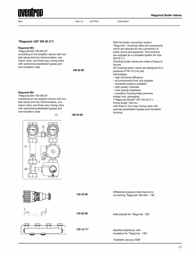
“Regumat-130” DN 25 (1”)
Regumat M3“Regumat M3-130 DN 25” consisting of one isolation device with two ball valves and two thermometers, one check valve, one three-way mixing valve with opintional presettable bypass and one insulation case.
168 52 85
Regumat M4“Regumat M4-130 DN 25” consisting of one isolation device with two ball valves and two thermometers, one check valve, one three-way mixing valve with opintional presettable bypass and one insulation case. (1) 168 54 85
With the boiler connection system “Regumat”, Oventrop offers all componentswhich are required for the connection ofboiler, pump and pipework. The productsare supplied as a complete system for sizeDN 25 (1”). Oventrop boiler valves are made of brass orbronze.All Oventrop boiler valves are designed for apressure of PN 10 (145 psi). Advantages: – high functional efficiency – all components from one supplier – complete systems available – high quality materials – time-saving installation – insulation housing helps preventsenergy loss. packaging. 1“Regumat M3,M4-130” DN 25 (1”) Pump length 130 mm with three or four-way mixing valve with optional presettable bypass and insulationhousing.
Differential pressure relief device forconverting "Regumat" M3+M4 - 130
Wall bracket for "Regumat -130"
Manifold distributor with insulation for “Regumat - 130”
*Available January 2008
135 33 90
135 20 96
135 15 71*

18
Item Item no. List Price Information
Solar Products
Regusol Controls 130
Regusol 130 169 70 65
Regusol EL - 130 169 80 65
OV Solar CollectorsFlat Plate Collector 540 00 18
8 Evacuated Tube Collector 540 00 08
16 Evacuated Tube Collector 540 00 16
16 Evacuated Tube Collector Kit* 540 00 16K*Includes (1) 169 80 65, (1) 540 00 16, (1) 540 00 80,
(1) 540 00 90, (1) 136 30 51, (1) 540 00 28
Solar Working Fluid5 Gallon NT/40 Glycol - Pre mixed to 40% 540 00 90
OV Solar Storage Tanks
60 Gallon Dual Coil Tank 540 00 6080 Gallon Dual Coil Tank 540 00 80115 Gallon Dual Coil Tank 540 01 15Single Coil w/ Electric Backup 540 0X XX ESingle Coil Tank 540 0X XX SC
Roof Mounting Hardware
Flat Roof/Ground Mount Kit 8 540 00 19Flat Roof/Ground Mount Kit 16 540 00 20Expansion Kit Flat Roof/Ground Mount 540 00 21Roof Mounting Kit - Shingle 540 00 22Roof mounting Kit Expansion - Shingle 540 00 23Roof Mounting Kit - Standing Metal Seam 540 00 24Roof mntng Kit Expansion - Standing Metal Seam 540 00 25Roof Mounting Kit - Tile 540 00 26Roof mounting Kit Expansion - Tile 540 00 27Roof Mounting Kit - Adjustable 540 00 28
Solar Valves
Filling and Flushing Device 136 30 51
Siting Tools
Solar Pathfinder w/Case 540 04 00
Transmission unit No Differential Controller"Regusol 130"safety group/airvent, Wilo, 0-4 GPM flow meter.Size: DN 25 (1”)Model: with Wilo-pump ST-16
Transmission unit "Regusol EL-130"safety group/airvent, Wilo, 0-4 GPM flow meter anddifferential controller.Size: DN 25 (1”)Model: with Wilo-pump ST-16

19
Mounting Hardware
Flat Roof/Ground Mount Kit 8540 00 19
Flat Roof/Ground Mount Kit 16540 00 20
Expansion Kit Flat Roof/Ground Mount540 00 21
Roof Mounting Kit Flush - Shingle540 00 22
Roof mounting Kit Expansion* - Shingle540 00 23
Roof Mounting Kit - Metal Seam540 00 24
Roof mounting Kit Expansion* - Metal Seam540 00 25
Roof Mounting Kit - Tile540 00 26
Roof mounting Kit Expansion* - Tile540 00 27
Roof Mounting Kit - Adjustable540 00 28
(2) Compression T-Fittings, (1) Air Vent, (1) Thermowell,(2) Pipe Adapters,(2) 53.5” rails, (2) 69.5” rails, (2) 90ºbraces, (2) single angle braces, (2) dual angle braces,(2) back brace rails, hardware
(2) Compression T-Fittings, (1) Air Vent, (1) Thermowell,(2) Pipe Adapters, (2) 53.5” rails, (2) 69.5” rails, (2) 90ºbraces, (2) single angle braces, (2) dual angle braces,(2) back brace rails, hardware
(1) Straight Compression Coupling, (1) AluminumManifold Sleeve(standard or extruded header), (1) “L”Profile Bracket
(2) Compression T-Fittings, (1) Air Vent, (1) Thermowell,(2) SS 750mm Flex Hoses, (2) Pipe Adapters, (4) RoofBrackets & Hardware
(1) Straight Compression Coupling, (4) Roof Brackets,(1) Aluminum Manifold Sleeve (standard or extrudedheader), (1) “L” Profile Bracket, Hardware
(2) Compression T-Fittings, (1) Air Vent, (1) Thermowell,(2) SS 750mm Flex Hoses, (2) Pipe Adapters, (4)Aluminum Standing Seam Clamps, Hardware
(1) Straight Compression Coupling, (4) AluminumStanding Seam Clamps, (1) Aluminum Manifold Sleeve(standard or extruded header), (1) “L” Profile Bracket,Hardware
(2) Compression T-Fittings, (1) Air Vent, (1) Thermowell,(2) SS 750mm Flex Hoses, (2) Pipe Adapters, (4) Tilemounting Brackets], Hardware
(1) Straight Compression Coupling, (4) Tile mountingBrackets, (1) Aluminum Manifold Sleeve (standard orextruded header), (1) “L” Profile Bracket, Hardware
(4) Aluminum channel feet, (2) Pieces 68” GalvanizedStrut, (1) Piece 48” Galvanized Strut, (1) Piece 56”Galvanized Strut, (4) 1/2” Bolt/Washer/Nut sets, (4)Type C Hinge leafs, (2) Type B Hinge leafs, (2) Type AHinge leafs, (22) 5/16” Bolt/Washers/Nut sets, (8) 1”Spacers, (2) Compression T-Fittings, (1) Air Vent, (1)Thermowell, (2) Pipe Adapters
Item Item no. Package Contents List Price
* Expansion kits for shingle, metal seam, and tile include roof mounting hardware

20
Bronze balancing valve with NPT thread
DN15 1⁄2" 106 10 04 DN 20 3⁄4" 106 10 06DN25 1" 106 10 08DN32 11⁄4" 106 10 10DN40 11⁄2" 106 10 12DN 50 2" 106 10 16
Bronze balancing valve with solder connection
DN15 1⁄2" 106 05 51 DN 20 3⁄4" 106 05 52DN25 1" 106 05 53DN32 11⁄4" 106 05 54DN40 11⁄2" 106 05 55DN 50 2" 106 05 56
Flanged cast iron balancing valve (ANSI)
DN 20 3 ⁄4" 106 29 46DN 25 1" 106 29 47DN32 11⁄4" 106 29 48 DN40 11⁄2" 106 29 49DN 50 2" 106 29 50DN 65 21⁄2" 106 29 51DN80 3" 106 29 52 DN 100 4" 106 29 53DN 125 5" 106 29 54 DN 150 6" 106 29 55 DN 200 8" 106 29 56DN 250 10" 106 29 57DN 300 12" 106 29 58
Cast iron balancing valve with groove connection
DN 65 21⁄2" 106 30 51DN80 3" 106 30 52 DN 100 4" 106 30 53DN 125 5" 106 30 54 DN 150 6" 106 30 55 DN 200 8" 106 30 56DN 250 10" 106 30 57DN 300 12" 106 30 58
Item Item no. List Price
Manual Balancing Valves

21
PE-Xc/AL/PE-X composition pipe “Copipe”
DN 12 16x 2 mm (1/2”)length per roll 200 m 150 02 55 - 200(657 ft)DN 15 20x2.5 mm (3/4”) length per roll 50 m 150 10 60 - 50(165 ft)DN 20 26x3 mm (1”)length per roll 50 m 150 10 66 - 50(165 ft)
PE-Xc plastic pipes "Copex”
1/2” OV-PEX O2 Barrier Pipelength per roll 300’ 460 00 02 - 300length per roll 1000’ 460 00 02 - 000
5/8” OV-PEX O2 Barrier Pipe length per roll 100’ 460 00 03 - 100length per roll 1000’ 460 00 03 - 000
3/4” OV-PEX O2 Barrier Pipe length per roll 100’ 460 00 04 - 100length per roll 1000’ 460 00 04 - 000
1” OV-PEX O2 length per roll 100’ 460 00 05 - 100length per roll 100’ 460 00 05 - 300
Item Item no. List Price per foot

22
Oventrop Corporation - Limited Warranty
Oventrop Corp. warrants to its “Customers” that all Oventrop products, used for heating and plumbing applica- tions and sold in accordance with these warranty provisions, shall be free from defects in material and workman- ship. “Customer” as used herein shall mean an end-user of Oventrop products. Five (5) years for all solar components from the date of purchase, unless otherwise specified in writing. In order to be eligible for a warranty claim, Products sold (1) must be installed and maintained professionally according to the relevant assembly instructions and the product manual, (2) must only be used for purposes provided in the Oventrop Corp.� s product description or assembly instructions, (3) must be exposed only to gaseous or liquid media approved for the product by Oventrop Corp., and (4) shall not be combined with products of other manufacturers unless otherwise stated in the product manual. Oventrop Corp.� s sole obligation hereunder shall be, at its option, to issue credit, repair or replace any component or part thereof which is proved to be defective. The limited warranty does not cover cost for transportation or labor charges (including installation and removal) unless such charges are authorized in writing in advance by the Oventrop Corp. Any repairs without the express written consent of Oventrop Corp. shall render this limited war- ranty invalid. Oventrop Corp. disclaims allowances for dismounting and consequential losses and damages. Warranty claims must be received by Oventrop Corp. within the applicable warranty period and within thirty (30) days from the cause for the claim occurred or was discovered. Upon receipt of prompt notice of a warranty claim, Oventrop Corp. shall have ten (10) business days in which to determine whether it acknowledges responsibility for any asserted defects in material or workmanship and the appropriate action to be taken. This limited warranty and any claims arising from the breach of warranty, or any other claim arising hereunder, shall be governed and construed under the laws of the State of New York. No other persons than Oventrop Corp. employees have any expressed or implied authority to bind Oventrop Corp. to any agreement or warranty of any kind without the express written consent of Oventrop Corp.
Disclaimer of Warranties: OVENTORP CORP. DISCLAIMS ANY WARRANTY NOT PROVIDED HEREIN INCLUDING THE IM- PLIED WARRANTY OF MERCHANTABILITY AND IMPLIED WARRANTY OF FITNESS FOR A PARTIC- ULAR PURPOSE. IT IS EXPRESSLY UNDERSTOOD THAT OVENTORP CORP. IS NOT RESPONSIBLE FOR ANY CONSEQUENTIAL OR OTHER DAMAGES THAT MAY ARISE FROM USING OVENTROP CORP. SYSTEM COMPONENTS. DAMAGE RESULTING FROM WATER FREEZING IN THE TUBING DOES NOT CONSTITUTE A DEFECT IN MATERIAL OR WORKMANSHIP, AND SHALL NOT BE COV- ERED BY THIS WARRANTY. OVENTROP-TUBING MAY NOT BE STORED IN DIRECT SUNLIGHT FOR ANY PERIOD LONGER THAN THREE WEEKS, OR THIS LIMITED WARRANTY BECOMES INVALID. OVENTORP CORP.DISCLAIMES ANY STATUTORY OR IMPLIED WARRANTY OF HABITABILITY. OVENTORP CORP. FURTHER DISCLAIMES ANY RESPONSIBILITY FOR LOSSES, EXPENSES, INCON- VENIENCES, SPECIAL, INDIRECT, SECONDARY, INCIDENTAL, OR CONSEQUENTIAL DAMAGES ARISING FROM OWNERSHIP OR USE OF THE ARTICLES SOLD HEREUNDER. THERE ARE NO WARRANTIES WHICH EXTEND BEYOND THE FACE HEREOF.
Oventrop Corporation - Limited Warranty

23
Oventrop Corp. 2007
OVENTROP CORP.TERMS AND CONDITIONS OF SALE
These General Terms and Conditions of Sale and Delivery (these “Terms”) are applicable to all U.S. customers (the “Customers” and each,individually, a “Customer”) of Oventrop Corp., a Delaware corporation (the “Company”).
1. Terms and Conditions of Sale:1.1 Company shall sell and deliver to Customer and Customer shall purchase and accept from Company the products (herein, the “Products”)described on or in any confirmed order, agreement or quotation, or any combination thereof (the “Order”), pursuant to the terms and conditions ofthe Order and those specified below, which taken together shall constitute the entire agreement between Company and Customer regarding theProducts (herein, this “Agreement”).1.2 No other terms or conditions shall be of any effect unless otherwise specifically agreed to by Company in a separate written agreement dulysigned by an officer of Company. Customer will be deemed to have assented to all Terms if any part of the Products is accepted by Customer. IfCustomer finds any Term not acceptable, Customer must so notify Company at once and must reject the Products delivered under thisAgreement. Any additional or different terms or conditions contained in Customer's order or response hereto shall be deemed objected to byCompany and shall be of no effect. No general terms and conditions of a Customer shall at any time form a part of the content of any contract oragreement between the Customer and the Company, even if they are not further expressly rejected by the Company.1.3 No Order is binding upon the Company until the earlier of acceptance of the Order in writing or the delivery of the Products to the Customer.Notwithstanding any prior acceptance of an Order by Company, Company shall have no obligation if the Customer is in breach of any of itsobligations hereunder, or any other agreement between the Customer and Company, at the time Company’s performance was due.1.4 All verbal agreements concerning the terms of any Order, including agreements made by telephone, shall have no force and effect unless anduntil acknowledged by the Company in writing.1.5 Customer shall bear all costs associated with the cancellation or modification of the Order.
2. Technical Data and Information in Catalogs: All technical data and specifications in catalogs, installation instructions, product documentation,price lists, etc. are bench marks only and are not warranted or guaranteed in any manner by the Company. Oventrop may from time to time adjustsuch technical data and specifications without notice.
3. Prices:3.1 Unless otherwise stated, all price quotations are EX WORKS (per Incoterms 2000) and do not include costs for packaging, postage or otherfreight charges, insurance or taxes, if any.3.2 Products prices will be governed by the Company's current prices in effect from time. A price list is available on request.3.3 Prices quoted in a currency other than Unites States Dollars are based on the official exchange rate on the date of the quote. Prices will beinvoiced on the basis of the currency exchange rate in effect on the date of confirmation of any Order.3.4 Company may without notice to Customer increase the price of the Products by the amount of any new or increased tax or duty (excludingfranchise, net income and excess profits taxes) which Company may be required to pay on the manufacture, sale, transportation, delivery, export,import or use of the Products or the materials required for their manufacture or which affects the cost of such materials
4. Terms of Payment:4.1 Payment terms are net 30 days from the date of invoice.4.2 Prices for future deliveries of Products will be governed by the Company’s current price list then in effect, which is available on request. Allpricing information contained in catalogs or price lists of Oventrop is subject to confirmation by Company.4.3 Company may change its prices and delivery terms for Products in its sole discretion, by giving Buyer at least ten (10) days prior notice thatthere will be a change. 4.4 Company may without notice to Buyer increase the price of the Products by the amount of any new or increased tax (excluding franchise, netincome and excess profits taxes) which Company may be required to pay on the manufacture, sale, transportation, import, export, delivery or useof the Products or the materials required for their manufacture or which affects the cost of such materials
5. Taxes: Purchaser agrees to provide Oventrop with its assigned tax exemption number and agrees to pay, in addition to the purchase price, allapplicable sales, use, excise, value added or other similar taxes.
6. Delivery Terms6.1 Except as specified elsewhere herein or in any other as otherwise agreed to in writing between Company and Buyer, orders for Products maynot be cancelled without Company’s prior written consent and the payment of cancellation charges. Company shall specify the cancellationcharges upon inquiry by Buyer.6.2 Title to and risk of loss for the Products shall pass to Buyer upon Company’s delivery thereof to carrier and any reference in these terms andconditions to "deliver" shall refer to such delivery.6.3 The Customer shall not be liable to Buyer for delays in delivery or damage to Products while in transit, irrespective of whether Customer orBuyer determined the mode of transportation
Terms and Conditions

7. Force Majeure: The Company shall not be liable to Buyer or any other person for any failure or delay in the performance of any obligationunder this Agreement due to events beyond its reasonable control, including, but not limited to, fire, storm, flood, earthquake, explosion,accident, acts of the public enemy, wars, riots and public disorder, sabotage, strikes, lockouts, labor disputes, labor shortages, work slowdown,stoppages or delays, shortages or failures or delays of energy, materials, supplies or equipment, transportation embargoes or delays, acts ofGod, breakdown in machinery or equipment, and, except as otherwise set forth in this Agreement, acts or regulations or priorities of the federal,state or local governments. Buyer shall not be liable for delay or failure to take Products as ordered due to any such event, except that Buyershall be liable to the Company for such delay or failure with respect to Products already in transit or specially made for Buyer which are notreadily saleable without loss to the Company. When the event operating to excuse performance by either party shall cease, this Agreement shallcontinue in full force until all deliveries have been completed
8. Indemnification by Customer:8.1 Except in cases of Company’s willful misconduct or gross negligence, Customer agrees to diligently defend, and to hold harmless andindemnify, Company and its directors, officers, employees, shareholders, affiliates, agents and representatives (the “Company Indemnitees”)from and against any and all liability, claims, lawsuits, losses, demands, damages, costs and expenses, including, without limitation, attorney’sfees and costs, expert’s fees and costs, and court costs, and in each case as such costs are incurred (the “Losses”), (i) arising directly orindirectly out of any use of the Products, whether authorized or unauthorized, and irrespective of whether such claim alleges personal injury,product liability, strict or absolute liability, breach of contract or implied contract or warranty, or any other claim of any nature on any theory ofrecovery, except to the extent such Losses have been incurred as a direct result of a breach of Company’s warranty pursuant to Section 10 orCompany’s gross negligence or willful misconduct, or (ii) arising out of any breach or misrepresentation of any of Customer’s representations orcovenants or other terms of this Agreement, including, without limitation, any failure to use or supervise use of the Products strictly inaccordance with the User Manual.8.2 Company will promptly notify Customer of any claim, suit or proceeding that Customer may have indemnification obligations with respect tounder this Section; provided, however, that any failure by Company to provide prompt written notice hereunder shall excuse Customer only tothe extent that Customer is prejudiced by such failure to give notice. Company shall cooperate with Customer with regard to the defense of anysuit or threatened suit. Customer may assume control of the defense of any such claim, proceeding or suit and shall have the authority to settleor otherwise dispose of any such suit or threatened suit, and to appeal any adverse judgment which may be entered, except that Customermust obtain Company’s prior written consent to any settlement unless the settlement involves solely the payment of money and all of suchpayment is payable by Customer, its insurers, and parties other than the Company Indemnitees.8.3 Customer shall notify Company in writing within 10 days of Customer’s receipt of knowledge of any accident or safety incident involving theProducts which results in personal injury or damage to property, or any government or similar investigation, claim or inquiry involving theProducts. Customer shall fully cooperate with Company in the investigation and determination of the cause of any such accident or incident, andshall make available to Company all statements, reports and tests made by Customer or made available to Customer by others. The furnishingof such information to Company and any investigation by Company of such information or incident report shall not in any way constitute anyassumption of any liability for such accident or incident by Company, nor shall it affect the indemnification obligations above.8.4 Customer represents and warrants that it has in place the necessary insurance and liability waivers to cover the use and operation of theProducts by Customer’s personnel, customers, and third-party users. In addition, Customer represents and warrants that it maintains a policy ofinsurance at levels sufficient to support the indemnification obligations assumed by it in this Agreement. Customer will notify Company promptlyif Customer’s coverage is materially reduced or cancelled.
9. Choice of law and forum: These terms and conditions and any order shall be construed and the rights of the parties shall be interpreted inaccordance with the laws of New York. The parties agree that courts located in the New York City, borough of Manhattan, shall be the exclusiveforum for any dispute arising hereunder or with respect to any order. The parties expressly waive any objections based on personal jurisdictionor venue and consent to service of process by certified mail, return receipt requested.
10. Limited Warranty: For Warranty terms, see ATTACHMENT A.
Terms and Conditions
24