probabilistic structural evaluation of uncertainties … kuguoglu qss group, inc., cleveland, ohio...
TRANSCRIPT

Latife KuguogluQSS Group, Inc., Cleveland, Ohio
Damian LudwiczakGlenn Research Center, Cleveland, Ohio
Probabilistic Structural Evaluationof Uncertainties in Radiator SandwichPanel Design
NASA/TM—2006-214116
March 2006
https://ntrs.nasa.gov/search.jsp?R=20060009943 2018-05-10T16:44:36+00:00Z

The NASA STI Program Office . . . in Profile
Since its founding, NASA has been dedicated tothe advancement of aeronautics and spacescience. The NASA Scientific and TechnicalInformation (STI) Program Office plays a key partin helping NASA maintain this important role.
The NASA STI Program Office is operated byLangley Research Center, the Lead Center forNASA’s scientific and technical information. TheNASA STI Program Office provides access to theNASA STI Database, the largest collection ofaeronautical and space science STI in the world.The Program Office is also NASA’s institutionalmechanism for disseminating the results of itsresearch and development activities. These resultsare published by NASA in the NASA STI ReportSeries, which includes the following report types:
• TECHNICAL PUBLICATION. Reports ofcompleted research or a major significantphase of research that present the results ofNASA programs and include extensive dataor theoretical analysis. Includes compilationsof significant scientific and technical data andinformation deemed to be of continuingreference value. NASA’s counterpart of peer-reviewed formal professional papers buthas less stringent limitations on manuscriptlength and extent of graphic presentations.
• TECHNICAL MEMORANDUM. Scientificand technical findings that are preliminary orof specialized interest, e.g., quick releasereports, working papers, and bibliographiesthat contain minimal annotation. Does notcontain extensive analysis.
• CONTRACTOR REPORT. Scientific andtechnical findings by NASA-sponsoredcontractors and grantees.
• CONFERENCE PUBLICATION. Collectedpapers from scientific and technicalconferences, symposia, seminars, or othermeetings sponsored or cosponsored byNASA.
• SPECIAL PUBLICATION. Scientific,technical, or historical information fromNASA programs, projects, and missions,often concerned with subjects havingsubstantial public interest.
• TECHNICAL TRANSLATION. English-language translations of foreign scientificand technical material pertinent to NASA’smission.
Specialized services that complement the STIProgram Office’s diverse offerings includecreating custom thesauri, building customizeddatabases, organizing and publishing researchresults . . . even providing videos.
For more information about the NASA STIProgram Office, see the following:
• Access the NASA STI Program Home Pageat http://www.sti.nasa.gov
• E-mail your question via the Internet [email protected]
• Fax your question to the NASA AccessHelp Desk at 301–621–0134
• Telephone the NASA Access Help Desk at301–621–0390
• Write to: NASA Access Help Desk NASA Center for AeroSpace Information 7121 Standard Drive Hanover, MD 21076
Latife KuguogluQSS Group, Inc., Cleveland, Ohio
Damian LudwiczakGlenn Research Center, Cleveland, Ohio
Probabilistic Structural Evaluationof Uncertainties in Radiator SandwichPanel Design
NASA/TM—2006-214116
March 2006
National Aeronautics andSpace Administration
Glenn Research Center
Prepared for theEarth & Space 2006sponsored by the American Society of Civil EngineersHouston, Texas, March 5–8, 2006
Acknowledgments
The authors would like to acknowledge Lee Mason,Glenn Research Center, for his funding support of this work.
Available from
NASA Center for Aerospace Information7121 Standard DriveHanover, MD 21076
National Technical Information Service5285 Port Royal RoadSpringfield, VA 22100
Trade names or manufacturers’ names are used in this report foridentification only. This usage does not constitute an officialendorsement, either expressed or implied, by the National
Aeronautics and Space Administration.
Available electronically at http://gltrs.grc.nasa.gov

NASA/TM—2006-214116 1
Probabilistic Structural Evaluation of Uncertainties in Radiator Sandwich Panel Design
Latife Kuguoglu QSS Group, Inc.
Cleveland, Ohio 44135
Damian Ludwiczak National Aeronautics and Space Administration
Glenn Research Center Cleveland, Ohio 44135
Abstract The Jupiter Icy Moons Orbiter (JIMO) Space System is part of the NASA's Prometheus Program. As
part of the JIMO engineering team at NASA Glenn Research Center, the structural design of the JIMO Heat Rejection Subsystem (HRS) is evaluated. An initial goal of this study was to perform sensitivity analyses to determine the relative importance of the input variables on the structural responses of the radiator panel. The desire was to let the sensitivity analysis information identify the important parameters. The probabilistic analysis methods illustrated here support this objective.
The probabilistic structural performance evaluation of a HRS radiator sandwich panel was performed. The radiator panel structural performance was assessed in the presence of uncertainties in the loading, fabrication process variables, and material properties. The stress and displacement contours of the deterministic structural analysis at mean probability was performed and results presented. It is followed by a probabilistic evaluation to determine the effect of the primitive variables on the radiator panel structural performance. Based on uncertainties in material properties, structural geometry and loading, the results of the displacement and stress analysis are used as an input file for the probabilistic analysis of the panel.
The sensitivity of the structural responses, such as maximum displacement and maximum tensile and compressive stresses of the facesheet in x and y directions and maximum VonMises stresses of the tube, to the loading and design variables is determined under the boundary condition where all edges of the radiator panel are pinned. Based on this study, design critical material and geometric parameters of the considered sandwich panel are identified.
Introduction The structural design of the spacecraft has three phases: (1) Conceptual Design: (a) The feasibility studies are conducted. Design details related to geometry and material selection
are identified. (b) Cost and risk is estimated (c) Requirements are derived (d) Candidate types of structures, materials are identified. (2) Preliminary design (a) The design parameters of the preferred candidates are recognized. (b) Material types and forms are selected. (c) Manufacturing plan is started. (d) Testing plans are started to be developed.
NASA/TM—2006-214116 2
(3) Detail Design (a) The detailed final design properties are defined and final drawings for manufacturing are
released. (b) Manufacturing and testing plans are developed.
The intention of our study was to support the feasibility assessment of the JIMO Space System design. The HRS accepts the waste heat from the Power Conversion Subsystem (PCS) and transports the heat
to radiator panels where it is rejected to space. Details about PCS for JIMO are given in references 1 and 2. Therefore, the structural design of the HRS radiator panel is derived by the thermal design requirements to reject the required heat load produced in the spacecraft and maintain acceptable operating temperatures. Heat sources on the spacecraft come from environmental inputs and internal heat generation. The produced amount of heat is rejected to the space through HRS radiator panels. The radiator structural requirements should not exceed the available spacecraft heat rejection surface area. The design parameters of the radiator panel such as required diameter of the tubing depend upon the heat rejection capability of the radiator panel and the configuration of the tubing on the panel. Therefore design parameters are subject to change until the design uncertainties have been addressed. That is why it is important to asses what design parameters have significant affect on the structural behavior of the radiator panel under the design or manufacturing uncertainties in order to achieve more reliable and robust design.
Most of the time analysts and designers are confronted with numerous uncertainties and design variability. To address these variables in traditional (deterministic) design, we apply safety factors. A reliability based design approach using probabilistic methods can explicitly model these uncertainties as random variables. When there is an uncertainty in the design or material parameters, using statistical techniques instead of comparing single numerical or test results, will help us to compare sets of data that reflect the variability of the structural responses as the result of uncertainties.
For complicated and expensive aerospace structures, the ability to perform reliability and risk assessment without using extensive hardware testing is critical to design and certification. The use of computational simulation is relied upon increasingly more as performance requirements for engineered structures increase and as a means of reducing testing. Since structural performance is directly affected by uncertainties associated with models or in physical parameters and loadings, the development and application of probabilistic analysis methods suitable for use with complex numerical models is needed. The traditional established method of accounting for uncertainties is based on a factor-of-safety approach. However, this approach generally leads to over-conservative and hence non-optimized.
The use of probabilistic methods will guide us to answer the following questions: (1) How these design uncertainties or manufacturing uncertainties affect structural performance of
the HRS radiator panel such as maximum displacement, maximum tensile and compressive stresses? (2) Which input parameters will have significant affect on the structural responses? (3) Which input parameters should be addressed to achieve a reliable design and improve the
quality?
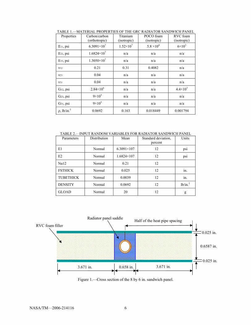
Geometry The outer dimensions of the radiator panel considered here are based on the preliminary radiator
design feasibility studies. The radiator panel dimensions are shown in figure 1, and are 0.7087 in. (1.8 cm) panel thickness, 8 in. (20.32 cm) of panel width (direction normal to tube direction) and 6 in. (15.24 cm) of panel depth. The tube and saddle are located at the center of the panel. The tube rests in the saddle and the saddle is placed between two facesheets. The thickness of the facesheets is 0.025 in. (0.127 cm). The material used for facesheets is K1100 Carbon-Carbon composite. The tube material is titanium, the outer diameter of the tube is 0.37 in. (0.9652 cm) and the thickness of the tube is 0.004 in. (0.01016 cm).
NASA/TM—2006-214116 3
Material Properties The material and mass properties of the HRS radiator sandwich panel for GRC design are given in
Table 1. Facesheets of the sandwich panel are made out of K1100 Carbon-Carbon (C-C) composites and titanium is used for the heat pipe. The saddle and filler is constructed from Poco Foam and Reticulated Vitreous Carbon (RVC), respectively.
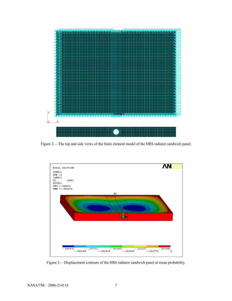
Finite Element Model The finite element model of the HRS radiator sandwich panel was generated using MSC/Patran. The
finite element model of the 3D sandwich panel as shown in figure 2, has 4,080 shell elements and 5,840 hexagonal solid elements. The total number of nodes and elements are 18786 and 19920, respectively. The total weight of the 3D full sandwich panel section is 0.263 lb (0.12 kg). The sandwich panel was subjected to a 20 g loading and all sides of the panel were placed in a pinned boundary condition.
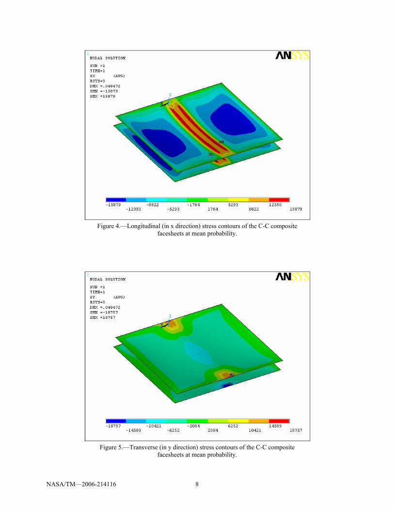
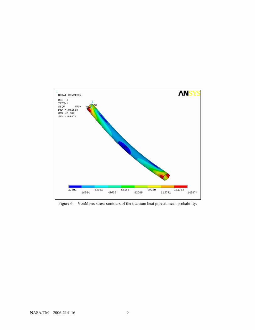
Finite Element Analysis (FEA) was conducted using ANSYS version 8.1(ANSYS, Inc., Canonsburg, PA). The displacement contours of the sandwich panel, stress contours of the C-C facesheets in x and y directions and VonMises stress contours of the tube at mean probability are shown in figures 3 to 6.
The Probabilistic Model This study shows how FEA and probabilistic design can be used to simulate the effects of design or
manufacturing uncertainties on the structural responses such as maximum displacement, maximum tensile and compressive stresses. The random variables describe modeling and manufacturing uncertainty. The uncertainties may come from conceptual modeling because of lack of data on the physical process involved or lack of system knowledge or from material properties such as elastic properties, density, local imperfections, etc. A Monte Carlo method is used for probabilistic simulation and Latin Hypercube method used for sampling (refs. 3 and 4).
The Monte Carlo Simulation method lets you simulate how virtual components behave the way they are built. Each one of the simulation loops represents one manufactured component that is subjected to a particular set of design or load conditions. The Latin Hypercube Sampling (LHS) technique has a sample “memory,” meaning it avoids repeating samples that have been evaluated before (it avoids clustering samples). It also forces the tails of a distribution to participate in the sampling process. For the Latin Hypercube Sampling technique the range of all random input variables is divided into n intervals with equal probability, where n is the number of sampling points (ref. 4). For each random variable each interval is “hit” only once with a sampling point. The process of generating sampling points with Latin Hypercube restricts the sampling points within the respective interval.
For this particular application, 100 finite element simulations using randomly generated input values provided sufficient data to accurately estimate the cumulative distribution function (CDF). The probabilistic analysis method repeatedly evaluates the deterministic model to generate samples of the model response, from which the response statistics and probability are approximated. The probabilistic analysis process in ANSYS version 8.1 consists of the general steps that are shown in figure 7 (ref. 3).
Table 1 contains a description of the 7 random variables. All variables were allowed to vary using normal distribution. The scatter range of the uncertainties considered for the probabilistic evaluation is defined as percentage or coefficient of variation from the mean value. The standard deviations for all of the parameters are established based on engineering judgment. The type of distribution considered for all parameters is Normal distribution. The mean value and standard deviation of all random input variables are shown in Table 2.

NASA/TM—2006-214116 4
The Probabilistic Analysis Results The effect of the uncertainties in the design variables on the maximum displacement, maximum
longitudinal and transverse tensile stresses of the C-C composite facesheets and on the minimum longitudinal and transverse compressive stresses of the C-C composite facesheets and on the maximum VonMises equivalent stress of the heat pipe is evaluated. The Cumulative Distribution Function (CDF) and sensitivity factors are determined.
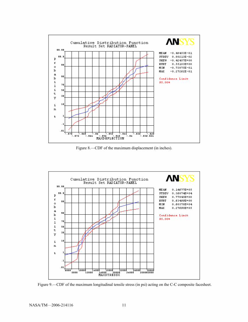
The plots of the CDFs for the maximum displacement, maximum longitudinal tensile and compressive stress, maximum transverse tensile and compressive stress and maximum VonMises stress are shown in figures 8 to 13. The upper and lower lines shown in CDF plots display the confidence bounds. The 95 percent confidence level is used for all responses. The confidence bounds quantify the accuracy of the probability level.
The CDF for the maximum displacement is shown in figure 8. The mean probabilistic maximum displacement is 0.048 in. The 0.01 percent probabilistic displacement is 0.075 in. and 99.99 percent probabilistic displacement is 0.025 in. The CDF for the longitudinal tensile and compressive stresses in the C-C composite facesheet are shown in figures 9 and 10. The mean maximum longitudinal tensile stress in the C-C composite facesheet is about 14677 psi with the 0.01 percent probabilistic stress of 6000 psi and 99.99 percent probabilistic stress of 27900 psi. The mean probabilistic maximum longitudinal compressive stress of the C-C composite facesheet is about −14677 psi with the 0.01 percent probabilistic stress of −27900 psi and 99.99 percent probabilistic stress of −6000 psi. The scatter in the maximum longitudinal tensile or compressive stress is about 21900 psi.
The CDF for the transverse tensile and compressive stresses in the C-C composite facesheet are shown in figures 11 and 12. The mean probabilistic maximum transverse tensile stress in the C-C composite facesheet is about 18775 psi with the 0.01 percent probabilistic stress of 12500 psi and 99.99 percent probabilistic stress of 26300 psi. The mean probabilistic maximum transverse compressive stress of the C-C composite facesheet is about −18775 psi with the 0.01 percent probabilistic stress of −26300 psi and 99.99 percent probabilistic stress of −12500 psi. The scatter in the maximum transverse tensile or compressive stress is about 13800 psi.
The CDF for the maximum VonMises stress in the heat pipe shown in figure 13. The mean probabilistic maximum VonMises stress is about 149770 psi with the 0.01 percent probabilistic stress of 74000 psi and 99.99 percent probabilistic stress of 224000 psi. The scatter in the maximum VonMises stress is about 21900 psi.
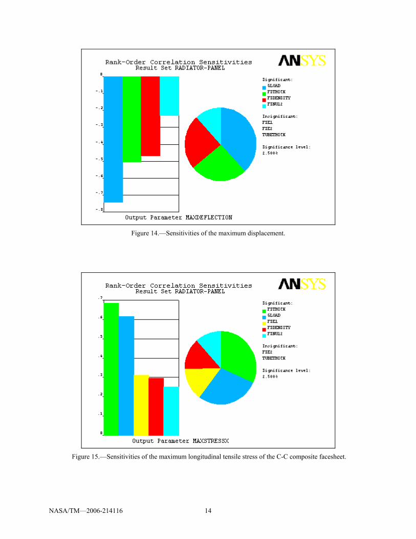
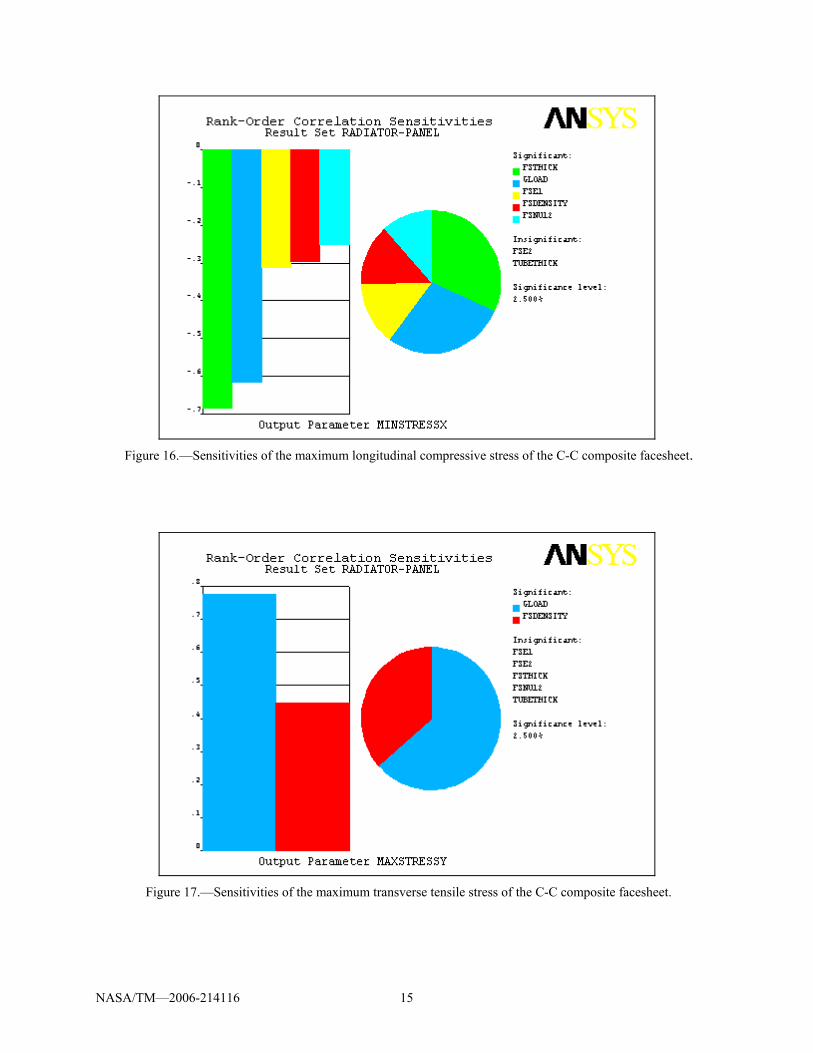
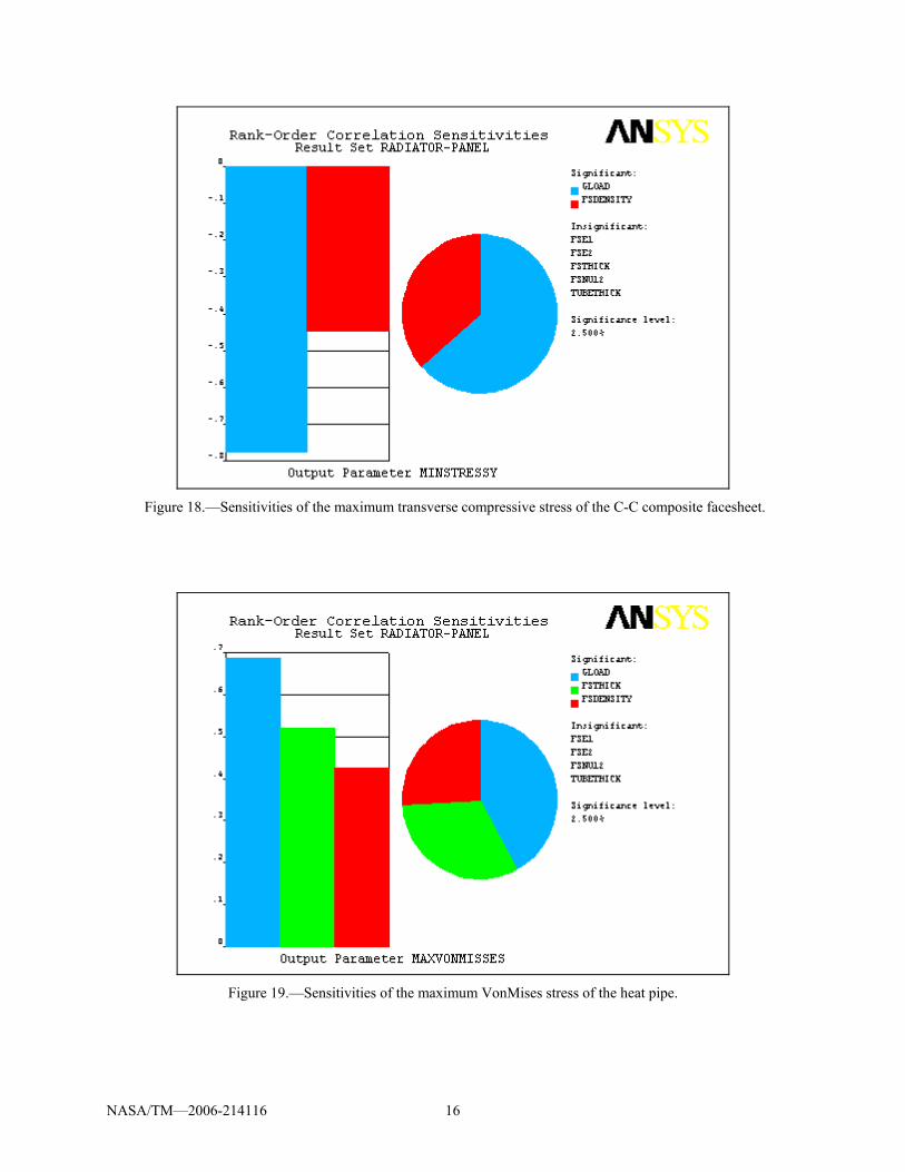
The probabilistic sensitivities of the input parameters on the maximum displacement of the sandwich panel is shown in figure 14. The most important input parameters that have significant effect on the maximum displacement, because of the uncertainties, are applied g load, facesheet thickness, facesheet density and facesheet Poisson’s ratio, in importance order. The maximum longitudinal tensile and compressive stress of the C-C composite facesheet is most sensitive to uncertainties in the facesheet thickness, g load, longitudinal modulus of elasticity of the C-C composite facesheet, facesheet density and in-plane Poisson’s ratio of the C-C composite facesheet, respectively (figs. 15 and 16). The uncertainties in g load and facesheet density have significant affect on the transverse maximum tensile and compressive stresses of the C-C composite facesheet (figs. 17 and 18). The maximum VonMises stress of the heat pipe is most sensitive to uncertainties in the g load, facesheet thickness, facesheet and density (fig. 19).
Positive sensitivity values indicate a positive change in the mean value will result in an increase in the computed probability. Negative sensitivities indicate that a positive increase in the mean value will result in a decrease in the computed probability.

NASA/TM—2006-214116 5
Conclusions For the JIMO HRS radiator panel section, the probabilistic evaluation of the structural responses to
the input parameters is presented. The Cumulative Distribution Function (CDF) and response sensitivity factors are calculated by the computational simulation in ANSYS version 8.1. The effect of the uncertainties in the input parameters on the maximum displacement, maximum longitudinal and transverse stresses of the facesheet and maximum VonMises stress of the heat pipe are evaluated. The following conclusions are drawn:
1. Controlling or modifying the scatter in the applied g load, facesheet thickness, facesheet density
and in-plane Poisson’s ratio of the C-C composite facesheet is critical to control the maximum deflection of the sandwich panel.
2. In general, results indicated that uncertainties of the facesheet thickness, g load, longitudinal modulus of elasticity of the C-C composite facesheet, facesheet density and in-plane Poisson’s ratio of the C-C composite facesheet have a significant effect on the maximum longitudinal tensile and compressive stresses of the facesheet.
3. The uncertainties in g load and facesheet density dominate and have significant effect on the maximum transverse tensile and compressive stresses of the facesheet.
4. The maximum VonMises stresses of the Heat Pipe is sensitive to the uncertainties in the g load, facesheet thickness and facesheet density.
5. The computational capability makes probabilistic analysis acceptable for practical applications. 6. Probabilistic sensitivities can be used to provide guidance for necessary design changes. 7. Probabilistic methods can be used to quantify the reliability of the HRS radiator panel to achieve a
more robust design and improve the quality.
References 1. Mason, L.S., “A Power Conversion Concept for the Jupiter Icy Moons Orbiter,” NASA/TM—2003-
212596, 2003. 2. Siamidis, J., “Heat Rejection Concepts for Brayton Power Conversion Systems,” NASA/TM—2005-
213337, 2005. 3. ANSYS Release 8.1 Documentation. 4. Florian, A., “An efficient sampling scheme: Latin Hypercube Sampling,” Probabilistic Engineering
Mechanics, 7, 123–130, 1992.
NASA/TM—2006-214116 6
RVC foam filler
0.658 in.
Half of the heat pipe spacing
0.025 in.
0.025 in.
3.671 in. 3.671 in.
0.6587 in.
Radiator panel saddle
TABLE 1.—MATERIAL PROPERTIES OF THE GRC RADIATOR SANDWICH PANEL Properties Carbon/carbon
(orthotropic) Titanium
(isotropic) POCO foam (isotropic)
RVC foam (isotropic)
E11, psi 6.3091×10⁷ 1.52×10⁷
5.8 ×10⁴ 6×10³
E22, psi 1.6824×10⁷ n/a n/a n/a
E33, psi 1.3050×10⁷ n/a n/a n/a
ν12 0.21 0.31 0.4082 n/a
ν23 0.04 n/a n/a n/a
ν31 0.04 n/a n/a n/a
G12, psi 2.84×10⁶ n/a n/a 4.4×10³
G23, psi 9×10⁵ n/a n/a n/a
G31, psi 9×10⁵ n/a n/a n/a
ρ, lb/in.3 0.0692 0.163 0.018449 0.001794
TABLE 2.—INPUT RANDOM VARIABLES FOR RADIATOR SANDWICH PANEL Parameters Distribution Mean Standard deviation,
percent Units
E1 Normal 6.3091×10⁷ 12 psi
E2 Normal 1.6824×10⁷ 12 psi
Nu12 Normal 0.21 12
FSTHICK Normal 0.025 12 in.
TUBETHICK Normal 0.0039 12 in.
DENSITY Normal 0.0692 12 lb/in.3
GLOAD Normal 20 12 g
Figure 1.—Cross section of the 8 by 6 in. sandwich panel.
NASA/TM—2006-214116 7
Figure 2.—The top and side views of the finite element model of the HRS radiator sandwich panel.
Figure 3.—Displacement contours of the HRS radiator sandwich panel at mean probability.
NASA/TM—2006-214116 8
Figure 4.—Longitudinal (in x direction) stress contours of the C-C composite
facesheets at mean probability.
Figure 5.—Transverse (in y direction) stress contours of the C-C composite
facesheets at mean probability.
NASA/TM—2006-214116 9
Figure 6.—VonMises stress contours of the titanium heat pipe at mean probability.

NASA/TM—2006-214116 10
Figure 7.—The probabilistic analysis process in ANSYS Version 8.1.
Generate an Analysis File: Build the model parametrically Obtain the solution Retrieve and assign to parameters the
quantities that will be used as random input variables and random output
Establish parameters in the ANSYS database which correspond to those used in the analysis file
Enter the probabilistic design System (PDS) and specify the analysis file name
State random input variables
Specify any correlations between the random variables (RV) if two (or more) random input
variables are statistically dependent on each other
Specify random output parameters
Choose the probabilistic design tool or method
Execute the loops required for the probabilistic design analysis
Review and plot the results of the probabilistic analysis
NASA/TM—2006-214116 11
Figure 8.—CDF of the maximum displacement (in inches).
Figure 9.—CDF of the maximum longitudinal tensile stress (in psi) acting on the C-C composite facesheet.

NASA/TM—2006-214116 12
Figure 10.—CDF of the maximum longitudinal compressive stress (in psi)
acting on the C-C composite facesheet.
Figure 11.—CDF of the maximum transverse tensile stress (in psi)
acting on the C-C composite facesheet.

NASA/TM—2006-214116 13
Figure 12.—CDF of the maximum transverse compressive stress (in psi)
acting on the C-C composite facesheet.
Figure 13.—CDF of the VonMises equivalent stress (in psi) acting on the heat pipe.
NASA/TM—2006-214116 14
Figure 14.—Sensitivities of the maximum displacement.
Figure 15.—Sensitivities of the maximum longitudinal tensile stress of the C-C composite facesheet.
NASA/TM—2006-214116 15
Figure 16.—Sensitivities of the maximum longitudinal compressive stress of the C-C composite facesheet.
Figure 17.—Sensitivities of the maximum transverse tensile stress of the C-C composite facesheet.
NASA/TM—2006-214116 16
Figure 18.—Sensitivities of the maximum transverse compressive stress of the C-C composite facesheet.
Figure 19.—Sensitivities of the maximum VonMises stress of the heat pipe.
This publication is available from the NASA Center for AeroSpace Information, 301–621–0390.
REPORT DOCUMENTATION PAGE
2. REPORT DATE
19. SECURITY CLASSIFICATION OF ABSTRACT
18. SECURITY CLASSIFICATION OF THIS PAGE
Public reporting burden for this collection of information is estimated to average 1 hour per response, including the time for reviewing instructions, searching existing data sources,gathering and maintaining the data needed, and completing and reviewing the collection of information. Send comments regarding this burden estimate or any other aspect of thiscollection of information, including suggestions for reducing this burden, to Washington Headquarters Services, Directorate for Information Operations and Reports, 1215 JeffersonDavis Highway, Suite 1204, Arlington, VA 22202-4302, and to the Office of Management and Budget, Paperwork Reduction Project (0704-0188), Washington, DC 20503.
NSN 7540-01-280-5500 Standard Form 298 (Rev. 2-89)Prescribed by ANSI Std. Z39-18298-102
Form Approved
OMB No. 0704-0188
12b. DISTRIBUTION CODE
8. PERFORMING ORGANIZATION REPORT NUMBER
5. FUNDING NUMBERS
3. REPORT TYPE AND DATES COVERED
4. TITLE AND SUBTITLE
6. AUTHOR(S)
7. PERFORMING ORGANIZATION NAME(S) AND ADDRESS(ES)
11. SUPPLEMENTARY NOTES
12a. DISTRIBUTION/AVAILABILITY STATEMENT
13. ABSTRACT (Maximum 200 words)
14. SUBJECT TERMS
17. SECURITY CLASSIFICATION OF REPORT
16. PRICE CODE
15. NUMBER OF PAGES
20. LIMITATION OF ABSTRACT
Unclassified Unclassified
Technical Memorandum
Unclassified
National Aeronautics and Space AdministrationJohn H. Glenn Research Center at Lewis FieldCleveland, Ohio 44135–3191
1. AGENCY USE ONLY (Leave blank)
10. SPONSORING/MONITORING AGENCY REPORT NUMBER
9. SPONSORING/MONITORING AGENCY NAME(S) AND ADDRESS(ES)
National Aeronautics and Space AdministrationWashington, DC 20546–0001
Available electronically at http://gltrs.grc.nasa.gov
March 2006
NASA TM—2006-214116
E–15451
WBS–22–794–20–69
22
Probabilistic Structural Evaluation of Uncertainties in Radiator SandwichPanel Design
Latife Kuguoglu and Damian Ludwiczak
Heat rejection subsystem; Radiator sandwich panel; Structural design; Compositematerials; Probabilistic analysis; Sensitivity analysis
Unclassified -UnlimitedSubject Categories: 05, 07, 18, 29, and 39
Prepared for the Earth & Space 2006 sponsored by the American Society of Civil Engineers, Houston, Texas,March 5–8, 2006. Latife Kuguoglu, QSS Group, Inc., 21000 Brookpark Road, Cleveland, Ohio 44135; andDamian Ludwiczak, NASA Glenn Research Center (now at NASA Kennedy Space Center, Kennedy Space Center,Florida 39899). Responsible person, Latife Kuguoglu, organization code DEV, 216–977–1372.
The Jupiter Icy Moons Orbiter (JIMO) Space System is part of the NASA’s Prometheus Program. As part of the JIMO engineeringteam at NASA Glenn Research Center, the structural design of the JIMO Heat Rejection Subsystem (HRS) is evaluated. An initial goalof this study was to perform sensitivity analyses to determine the relative importance of the input variables on the structural responsesof the radiator panel. The desire was to let the sensitivity analysis information identify the important parameters. The probabilisticanalysis methods illustrated here support this objective. The probabilistic structural performance evaluation of a HRS radiatorsandwich panel was performed. The radiator panel structural performance was assessed in the presence of uncertainties in the loading,fabrication process variables, and material properties. The stress and displacement contours of the deterministic structural analysis atmean probability was performed and results presented. It is followed by a probabilistic evaluation to determine the effect of theprimitive variables on the radiator panel structural performance. Based on uncertainties in material properties, structural geometry andloading, the results of the displacement and stress analysis are used as an input file for the probabilistic analysis of the panel. Thesensitivity of the structural responses, such as maximum displacement and maximum tensile and compressive stresses of the facesheetin x and y directions and maximum VonMises stresses of the tube, to the loading and design variables is determined under theboundary condition where all edges of the radiator panel are pinned. Based on this study, design critical material and geometricparameters of the considered sandwich panel are identified.

