ps640g parts manual - middleby parts/ps600 parts...ii retain this manual for future reference....
TRANSCRIPT

PARTS MANUALfor domestic and standard export ovens
©2007 Middleby Marshall Inc.
is a registered trademark of Middleby Marshall, Inc. All rights reserved.
Middleby Cooking Systems Group • 1400 Toastmaster Drive • Elgin, IL 60120 • (847)741-3300 • FAX (847)429-7508
PS640/740/840 Series Ovens
P/N: 640May, 2009 Rev. D
PS640/740/840 SeriesElectric & GasDomestic & Std. ExportENGLISH
Model Combinations: • Single Oven
• Double Oven (Two-Stack)• Triple Oven (Three-Stack)

ii
RETAIN THIS MANUAL FOR FUTURE REFERENCE.Middleby Cooking Systems Group • 1400 Toastmaster Drive • Elgin, IL 60120 USA • (847)741-3300 • FAX (847) 429-7508
www.Middleby-Marshall.com
NOTICE: This parts manual should be kept in a prominent, easily reachable location.Ovens are shipped from the factory configured for use with natural gas. If permitted by local, national andinternational codes, at the time of installation the oven may be converted to propane gas operation. This conversionrequires the use of at Gas Conversion Kit that is supplied with the oven. For CE-approved ovens, the conversion isdescribed in the Installation section of this Manual. For domestic and standard export ovens, instructions areincluded in the Gas Conversion Kit.It is suggested to obtain a service contract with a Middleby Marshall Authorized Service Agent.
WARNINGPOST, IN A PROMINENT LOCATION, THE EMERGENCY TELEPHONE NUMBER OF YOUR LOCAL GAS
SUPPLIER AND INSTRUCTIONS TO BE FOLLOWED IN THE EVENT YOU SMELL GAS.Instructions to be followed in the event the user smells gas shall be obtained by consulting the local gassupplier. If the smell of gas is detected, immediately call the emergency phone number of your local Gas
Company. They will have personnel and provisions available to correct the problem.WARNING
FOR YOUR SAFETY, DO NOT STORE OR USE GASOLINE OR OTHER FLAMMABLE VAPORSAND LIQUIDS IN THE VICINITY OF THIS OR ANY OTHER APPLIANCE.
WARNINGImproper installation, adjustment, alteration, service, or maintenance can cause
property damage, injury, or death. Read the installation, operation, and maintenance instructionsthoroughly before installing or servicing this equipment.
WARNINGDO NOT SPRAY AEROSOLS IN THE VICINITY OF THIS APPLIANCE WHILE IT IS IN OPERATION.
IMPORTANTAn electrical wiring diagram for the oven is located inside the machinery compartment.
IMPORTANTIt is the customer’s responsibility to report any concealed or non-concealed damage to the
freight company. Retain all shipping materials until it is certain that the equipment hasnot suffered concealed shipping damage.
NOTICECONTACT YOUR MIDDLEBY MARSHALL AUTHORIZED SERVICE AGENT TO INSTALL ANDPERFORM MAINENANCE AND REPAIRS AND IF NECESSARY TO CONVERT EQUIPMENT
FOR USE WITH OTHER GASES. AN AUTHORIZED SERVICE AGENCY DIRECTORY ISSUPPLIED WITH YOUR OVEN.
NOTICEUsing any parts other than genuine Middleby Marshall factory manufactured parts relieves the manufacturer
of all warranty and liability.NOTICE
Middleby Marshall (Manufacturer) reserves the right to change specifications at any time.NOTICE
The equipment warranty is not valid unless the oven is installed, started and demonstrated under thesupervision of a factory certified installer.
NOTICETHIS EQUIPMENT IS ONLY FOR PROFESSIONAL USE AND SHALL BE USED
BY QUALIFIED PERSONNEL.
iii
MIDDLEBY MARSHALL INC.OVEN LIMITED WARRANTY
(Non U.S.A.)The Seller warrants equipment manufactured by it to be free fromdefects in material and workmanship for which it is responsible. TheSeller’s obligation under this warranty shall be limited to replacing orrepairing, at Seller’s option, without charge, F.O.B. Seller’s factory,any part found to be defective and any labor and material expenseincurred by Seller in repairing or replacing such part. Such warrantyis limited to a period of one year from date of original installation or15 months from date of shipment from Seller’s factory, whichever isearlier, provided that terms of payment have been fully met. All laborshall be performed during regular working hours. Overtime premiumwill be charged to the Buyer.
This warranty is not valid unless equipment is installed, started,and demonstrated under the supervision of a factory-autho-rized installer.
Normal maintenance functions, including lubrication, adjustment ofairflow, thermostats, door mechanisms, microswitches, burners andpilot burners, and replacement of light bulbs, fuses and indicatinglights, are not covered by warranty.
Any repairs or replacements of defective parts shall be performed bySeller’s authorized service personnel. Seller shall not be respon-sible for any costs incurred if the work is performed by other thanSeller’s authorized service personnel.
When returning any part under warranty, the part must be intact andcomplete, without evidence of misuse or abuse, freight prepaid.
Seller shall not be liable for consequential damages of any kindwhich occur during the course of installation of equipment, or whichresult from the use or misuse by Buyer, its employees or others ofthe equipment supplied hereunder, and Buyer’s sole and exclusiveremedy against Seller for any breach of the foregoing warranty orotherwise shall be for the repair or replacement of the equipment orparts thereof affected by such breach.
The foregoing warranty shall be valid and binding upon Seller if andonly if Buyer loads, operates and maintains the equipment suppliedhereunder in accordance with the instruction manual provided toBuyer. Seller does not guarantee the process of manufacture byBuyer or the quality of product to be produced by the equipmentsupplied hereunder and Seller shall not be liable for any prospectiveor lost profits of Buyer.
THE FOREGOING WARRANTY IS EXCLUSIVE AND IN LIEU OFALL OTHER EXPRESS AND IMPLIED WARRANTIES WHATSO-EVER. SPECIFICALLY THERE ARE NO IMPLIED WARRANTIESOF MERCHANTABILITY OR OF FITNESS FOR A PARTICULARPURPOSE.
The foregoing shall be Seller’s sole and exclusive obligation andBuyer’s sole and exclusive remedy for any action, whether in breachof contract or negligence. In no event shall seller be liable for a sumin excess of the purchase price of the item.
Model No.Modéle No.
Serial No.Serié No.
Installation DateDate d'installation
MIDDLEBY MARSHALLNO QUIBBLE LIMITED WARRANTY
(U.S.A. ONLY)
MIDDLEBY MARSHALL, HEREINAFTER REFERRED TOAS “THE SELLER”, WARRANTS EQUIPMENT MANUFAC-TURED BY IT TO BE FREE FROM DEFECTS IN MATE-RIAL AND WORKMANSHIP FOR WHICH IT IS RESPON-SIBLE. THE SELLER’S OBLIGATION UNDER THIS WAR-RANTY SHALL BE LIMITED TO REPLACING OR REPAIR-ING, AT SELLER’S OPTION, WITHOUT CHARGE, ANYPART FOUND TO BE DEFECTIVE AND ANY LABOR ANDMATERIAL EXPENSE INCURRED BY SELLER IN REPAIR-ING OR REPLACING SUCH PART. SUCH WARRANTYSHALL BE LIMITED TO THE ORIGINAL PURCHASERONLY AND SHALL BE EFFECTIVE FOR A PERIOD OFONE YEAR FROM DATE OF ORIGINAL INSTALLATION, OR18 MONTHS FROM DATE OF PURCHASE, WHICHEVERIS EARLIER, PROVIDED THAT TERMS OF PAYMENT HAVEBEEN FULLY MET.
This warranty is valid only if the equipment is installed, started,and demonstrated under the supervision of a factory-autho-rized installer.
Normal maintenance functions, including lubrication, clean-ing, or customer abuse, are not covered by this no quibblewarranty.
Seller shall be responsible only for repairs or replacementsof defective parts performed by Seller’s authorized servicepersonnel. Authorized service agencies are located in prin-cipal cities throughout the contiguous United States, Alaska,and Hawaii. This warranty is valid in the 50 United Statesand is void elsewhere unless the product is purchasedthrough Middleby International with warranty included.
The foregoing warranty is exclusive and in lieu of all otherwarranties, expressed or implied. There are no impliedwarranties of merchantability or of fitness for a particu-lar purpose.
The foregoing shall be Seller’s sole and exclusive obligationand Buyer’s sole and exclusive remedy for any action, in-cluding breach of contract or negligence. In no event shallSeller be liable for a sum in excess of the purchase price ofthe item. Seller shall not be liable for any prospective or lostprofits of Buyer.
This warranty is effective on Middleby Marshall equip-ment sold on, or after, February 15, 1995.
© 2014 - Middleby Marshall, A Middleby Company.The Middleby Marshall logo is a registered trademark of Middleby Marshall, A Middleby Company.
Middleby Marshall Inc. • 1400 Toastmaster Drive • Elgin, Illinois 60120-9272 U.S.A. • (847) 741-3300 • FAX: (847) 429-7508

iv
NOTEWiring Diagrams are in back of this Manual.The diagram for each oven is also on the lower
inner surface of its Control Console.
Page
SECTION 1 – DESCRIPTION ............................................ 1I. OVEN USES ............................................................ 1II. OVEN COMPONENTS ............................................ 1
A. Conveyor Motor Drive ................................... 1B. Crumb Pans .................................................. 1C. Conveyor ....................................................... 1D. End Plugs ...................................................... 1E. Eyebrows ...................................................... 1F. Window ......................................................... 1G. Machinery Compartment Access Panel ........ 1H. Serial Plate .................................................... 1I. Control Panel ................................................ 1J. Photo Cell ..................................................... 1K. Gas Burner .................................................... 1L. Blowers ......................................................... 1M. Air Fingers ..................................................... 1
III. OVEN SPECIFICATIONS ........................................ 2A. Dimensions ................................................... 2B. General Specifications .................................. 2C. Electrical Specifications for
PS640 Gas Ovens ........................................ 2D. Gas Orifice and Pressure Specifications
for PS640 Gas Ovens ................................... 2
SECTION 2 – PARTS BREAK OUT................................... 3
aisjdf
TABLE OF CONTENTS

I. OVEN USES
PS640 Series Ovens can be used to bake and/or cook a widevariety of food products, such as pizza, pizza –type products,cookies, sandwiches and others.
II. OVEN COMPONENTS – see Figure 1-1.
A. Conveyor Drive Motor: Moves the conveyor.
B. Crumb Pans: Catch crumbs and other materials that dropthrough the conveyor belt. One crumb pan is located ateach end of the conveyor.
C. Conveyor: Moves the food product through the oven.
D. End Plugs: Allow access to the oven’s interior.
E. Eyebrows: Can be adjusted to various heights to preventheat loss into the environment.
F. Window: Allows the user to access food products insidethe baking chamber.
G. Machinery Compartment Access Panel: Allows accessto the oven’s interior and control components. No userserviceable parts are located in the machinery compart-ment.
H. Serial Plate: Provides specifications for the oven thataffect installation and operation. Refer to Section 2,Installation for details.
I. Control Panel: Location of the operating controls for theoven. Refer to Section 3, Operation, for details.
J. Photo Cell: Turns oven On when beam is interrupted.
Not Shown:
K. Gas Burner (gas ovens): Heat air, which is then projectedto the air fingers by the blowers.
L. Blowers: Project hot air from the burner or heating elementto the air fingers.
M. Air Fingers: Project streams of hot air onto the foodproduct.
SECTION 1 – DESCRIPTION
Figure 1-1. Oven Components
F
ED
JI
G
H
A
CB
1

I. OVEN SPECIFICATIONSTable 1-1 Dimensions Single Oven Double Oven Triple Ove
Overall Height 48-3/16″ (1219mm) 62-3/4″ (1575mm) 78-11/16″ (1981mm)
Overall Depth 60″ (1524mm) 60″ (1524mm) 60″ (1524mm)
Overall Length 76-1/2″ (1930mm) 76-1/2″ (1930mm) 76-1/2″ (1930mm)
Conveyor Width – belt width is 32″ 33-1/2″ (838mm) 33-1/2″ (838mm) 33-1/2″ (838mm)or 2 × 15″ (381mm) or 2 × 15″ (381mm) or 2 × 15″ (381mm)
Shortened Exit Conveyor - 24″″″″″ Single Oven Double Oven Triple Ove
Overall Depth 52.75″ (1340mm) 52.75″ (1340mm) 52.75″ (1340mm)
Overall Length 69″ (1753mm) 69″ (1753mm) 69″ (1753mm)
* All other dimension are the same
Recommended Minimum Clearances
Rear of Oven to Wall 3″ (76mm) 3″ (76mm) 3″ (76mm)
Control end of conveyor to Wall 1″ (25.4mm) 1″ (25.4mm) 1″ (25.4mm)
Non-control end of conveyor to Wall) 1″ (25.4mm) 1″ (25.4mm) 1″ (25.4mm)
Table 1-2: General Specifications PS640 GAS 32″″″″″ Belt 24″″″″″ Belt
Weight 1150 lbs. (522kg) 1150 lbs. (522kg)
Rated Heat Input 99,000 BTU (25,000kcal, 29 kW/hr) 99,000 BTU (25,000kcal, 29 kW/hr)
Maximum Operation Temperature 600°F / 315°C 600°F / 315°C
Air Blowers Two Blowers at 1900 RPM Two Blowers at 1900 RPM
Warmup Time 15 min. 15 min.
Table 1-3: Electrical specifications for PS640G gas ovens
Main Blower Control Circuit Phase Freq Current Poles WiresVoltage Voltage Draw
208-240VAC 208-240VAC 1Ph 50/60Hz 11-9.6 Amp 2 Pole 3 Wire (2 hot, 1 gd)
Table 1-4: Gas orifice and pressure specifications for PS640G gas ovens
Gas Main Orifice I.D. Supply (Inlet) Orifice (Manifold) BypassType PS640G Pressure Pressure Pressure
Natural 0.1065″ (0.120mm) 6-8″ W.C. (14.9 - 19.9mbar) 3.5″ W.C. (8.7mbar) 0.25-0.3″ W.C. (0.6-0.8 mbar)
Propane 0.067″ (1.9mm) 11-14″ W.C. (27.4 - 34.9mbar) 10.0″ W.C. (24.9mbar) 0.9-1.0″ W.C. (2.2-2.5 mbar)
IMPORTANT – Additional electrical information is provided on the oven’s serial plate, and on the wiring diagram inside the machinery compartment.
2
NOTEWiring Diagrams are contained in Section 5 of this Manual
and are also located inside the oven at thebottom of the Control Panel.
Additional electrical information is provided on the oven's serial plate.
This Manual Must Be Kept For Future Reference
GAS ORIFICE AND PRESSURE SPECIFICATIONS (PER OVEN CAVITY) - CE OVENS
Supply (Inlet) Pressure
IT,PT,ES,SE,Main UK,CH,IT,AT, SE,CH,AT,DK, BE,IE,IT,PT, Orifice Rated
Gas Orifice DK,FI NL DE BE,FR FI,DE,NL ES,UK (Manifold) HeatType dia. I2H I2L I2E I2E+ I3B/P I3+ Pressure Input
G20 0.120″ 20 -- 20 20 -- -- 11.21 22.36(3.05 mm) mbar mbar mbar mbar kW-hr.
G25 0.120″ -- 25 -- -- -- -- 16.19 22.36(3.05 mm) mbar mbar kW-hr.
G30 0.075″ -- -- -- -- 29 or 50 28-30, 37 26.2 22.59(1.9 mm) mbar or 50 mbar mbar kW-hr.

SECTION 2 – INSTALLATION
WARNING – After any conversions, readjustments, or service work on the oven:• Perform a gas leak test. • Test for proper combustion and gas supply.• Test for correct air supply, particularly to the • Check that the ventilation system is in operation.
burner blower.
WARNING - Keep the appliance area free and clear of combustibles.
WARNING – The oven must be installed on an even (level) non-flammable flooring and any adjacent wallsmust be non-flammable. Recommended minimum clearances are specified in the Description section ofthis manual.
WARNING – Do not obstruct the flow of combustion and ventilation air to and from your oven. There mustbe no obstructions around or underneath the oven. Constructional changes to the area where the ovenis installed shall not affect the air supply to the oven.
CAUTION: To reduce the risk of fire, the appliance is to be mounted on floors of noncombustible construction withnoncombustible flooring and surface finish and with no combustible material against the underside thereof, or onnoncombustible slabs or arches having no combustible material against the underside thereof, such constructionshall in all cases extend not less than 12 inches (304mm) beyond the equipment on all sides.
CAUTION: For additional installation information, contact your local Authorized Service Agent.
NOTE – There must be adequate clearance between the oven and combustible construction. Clearance must alsobe provided for servicing and for proper operation.
NOTE – An electrical wiring diagram for the oven is located inside the machinery compartment.
NOTE: All aspects of the oven installation, including placement, utility connections, and ventilation requirements,must conform with any applicable local, national, or international codes. These codes supersede the requirementsand guidelines provided in this manual.
NOTE: In the USA, the oven installation must conform to local codes. In the absence of local codes, gas oveninstallations must conform with the National Fuel Gas Code, ANSI Z223.1. Gas and electric ovens, when installed,must be electrically grounded in accordance with local codes, or in the absence of local codes, with the NationalElectrical Code (NEC), or ANSI/NFPA70.
NOTE: In Canada, the oven installation must conform with local codes. In the absence of local codes, gasoven installations must conform with the Natural Gas Installation Code, CAN/CGA-B149.1, or the Propane GasInstallation Code, CAN/CGA-B149.2, as applicable. Gas and electric ovens, when installed, must be electricallygrounded in accordance with local codes, or in the absence of local codes, with the Canadian Electrical CodeCSA C22.2.
NOTE: In Australia, the oven installation must conform with local codes. In the absence of local codes, gasoven installations must conform with the requirements of AS5601/AG601, Gas, Electricity, and any other relevantstatutory regulations.
3

3
2
4
65
1
PARTS LIST FOR SERIES PS640 GAS OVENINSTALLATION KIT
P/N 61452(Two required for double oven)(Three required for triple oven)
ITEMNO. QTY PART NO. DESCRIPTION
1 1 22361-0001 FLEXIBLE GAS HOSE
2 1 61823 CONVEYOR END STOP, 18″3 1 31461 CONVEYOR LEFT REAR STOP, 21.25″4 1 42612 SERVICE AGENCY DIRECTORY
5 1 22500-0080 LABEL, MM
6 1 51054 ASSY, HANDLE & DOOR
Figure 2-1A. PS640-Series Gas Oven Installation Parts
4
PS640 24″″″″″ OVEN INSTALLATIONREQUIRED KITS AND EQUIPMENT
PS640 PS640 PS640 PS640Gas Oven Single Oven DoubleOven TripleOven
Installation Option Base w/ OptionBase w/ OptionBase w/TYPE OF INSTALLATION Kit 15″ Legs, 6″ Legs, Casters& Top
Casters & Top Casters & Top KitKit Kit
P/N61452 P/N61123 P/N61457 P/N61458
PS640 Single Gas Oven 1 1
PS640 Double Gas Oven 2 1
PS640 Triple Gas Oven 3 1

3
2
4
65
1
PARTS LIST FOR SERIES PS640 GAS OVENINSTALLATION KIT
P/N 61033(Two required for double oven)(Three required for triple oven)
Figure 2-1B. PS640-Series Gas Oven Installation Parts
PS640 32″″″″″ OVEN INSTALLATIONREQUIRED KITS AND EQUIPMENT
PS640 PS640 PS640 PS640Gas Oven Single Oven DoubleOven TripleOven
Installation Option Base w/ OptionBase w/ OptionBase w/TYPE OF INSTALLATION Kit 15″ Legs, 6″ Legs, Casters& Top
Casters & Top Casters & Top KitKit Kit
P/N61033 P/N59720 P/N59725 P/N59726
PS640 Single Gas Oven 1 1
PS640 Double Gas Oven 2 1
PS640 Triple Gas Oven 3 1
ITEMNO. QTY PART NO. DESCRIPTION
1 1 22361-0001 FLEXIBLE GAS HOSE
2 1 61823 CONVEYOR END STOP
3 1 55027 CONVEYOR LEFT REAR STOP
4 1 42612 SERVICE AGENCY DIRECTORY
5 1 22500-0080 LABEL, MM
6 1 51054 ASSY, HANDLE & DOOR
5

Figure 2-2A. Model PS640 24″″″″″ Single OvenOption Base with Legs and Top
PARTS LIST FOR PS640 SERIES 24″″″″″ SINGLE OVEN OPTION - BASE w/15″″″″″ LEGS & TOPP/N 61123
HARD WARE BAG 5, 6, 7, 10 & 11
1
2
3
4
9
8
12
ITEM NO. QTY PART NO. DESCRIPTION
1 1 61126 COMPLETE BASE WELDMENT
2 4 37900-0024 TOP PLATE, LEG WELDMENT
3 2 22290-0009 SWIVEL CASTER W/BRAKE FLAT PLATE
4 2 22290-0010 SWIVEL CASTER FLAT PLATE
5 32 2000531 3/8″-16 × 1″ HEX SCREW, SST
6 32 21416-0001 3/8″ FLAT WASHER, SS
7 32 21422-0001 3/8″ SPLIT LOCK WASHER, ZP
8 1 22450-0228 RESTRAINT CABLE ASSEMBLY
9 1 61125 TOP COVER
10 2 59677 SCR, MS SL TR HD 10-32 × 2-1/2″
11 2 7A2S15 SCR, MS STR TRSHD 10-32 × 3/4″
12 1 61128 SUPPORT, SHELF
6

Figure 2-2B. Model PS640 32″″″″″ Single OvenOption Base with Legs and Top
PARTS LIST FOR PS640 32″″″″″ SERIES SINGLE OVEN OPTION - BASE w/15″″″″″ LEGS & TOPP/N 59720
HARDWARE BAG 5, 6, 7, 10 & 11
1
2
3
4
9
8
12
ITEM NO. QTY PART NO. DESCRIPTION
1 1 60287 COMPLETE BASE WELDMENT
2 4 37900-0024 TOP PLATE, LEG WELDMENT
3 2 22290-0009 SWIVEL CASTER W/BRAKE FLAT PLATE
4 2 22290-0010 SWIVEL CASTER FLAT PLATE
5 32 2000531 3/8″-16 × 1″ HEX SCREW, SST
6 32 21416-0001 3/8″ FLAT WASHER, SS
7 32 21422-0001 3/8″ SPLIT LOCK WASHER, ZP
8 1 22450-0228 RESTRAINT CABLE ASSEMBLY
9 1 59560 TOP COVER
10 2 59677 SCR, MS SL TR HD 10-32 × 2-1/2″
11 2 7A2S15 SCR, MS STR TRSHD 10-32 × 3/4″
12 1 59724 SUPPORT, SHELF
7

ITEM NO. QTY PART NO. DESCRIPTION
1 1 61126 COMPLETE BASE WELDMENT
2 4 37900-0102 TOP PLATE, LEG WELDMENT
3 2 22290-0009 SWIVEL CASTER W/BRAKE FLAT PLATE
4 2 22290-0010 SWIVEL CASTER FLAT PLATE
5 32 2000531 3/8″-16 × 1 HEX SCREW, SST
6 32 21416-0001 3/8″ FLAT WASHER, SS
7 32 21422-0001 3/8″ SPLIT LOCK WASHER, ZP
8 1 22450-0228 RESTRAINT CABLE ASSEMBLY
9 1 61125 TOP COVER
10 2 59677 SCR, MS SL TR HD 10-32 × 2-1/2″
11 2 7A2S15 SCR, MS STR TRSHD 10-32 × 3/4″
12 1 61128 SUPPORT, SHELF
PARTS LIST FOR PS640 SERIES 24″″″″″ DOUBLE OVEN OPTION - BASE w/6″″″″″ LEGS & TOPP/N 61457
HARDWARE BA G 5, 6, 7, 10 & 11
1
2
3
4
9
8
12
Figure 2-3A. Model PS640 24″″″″″ Double OvenOption Base with Legs and Top
8
ITEM NO. QTY PART NO. DESCRIPTION
1 1 60287 COMPLETE BASE WELDMENT
2 4 37900-0102 TOP PLATE, LEG WELDMENT
3 2 22290-0009 SWIVEL CASTER W/BRAKE FLAT PLATE
4 2 22290-0010 SWIVEL CASTER FLAT PLATE
5 32 2000531 3/8″-16 × 1 HEX SCREW, SST
6 32 21416-0001 3/8″ FLAT WASHER, SS
7 32 21422-0001 3/8″ SPLIT LOCK WASHER, ZP
8 1 22450-0228 RESTRAINT CABLE ASSEMBLY
9 1 59560 TOP COVER
10 2 59677 SCR, MS SL TR HD 10-32 × 2-1/2″
11 2 7A2S15 SCR, MS STR TRSHD 10-32 × 3/4″
12 1 59724 SUPPORT, SHELF
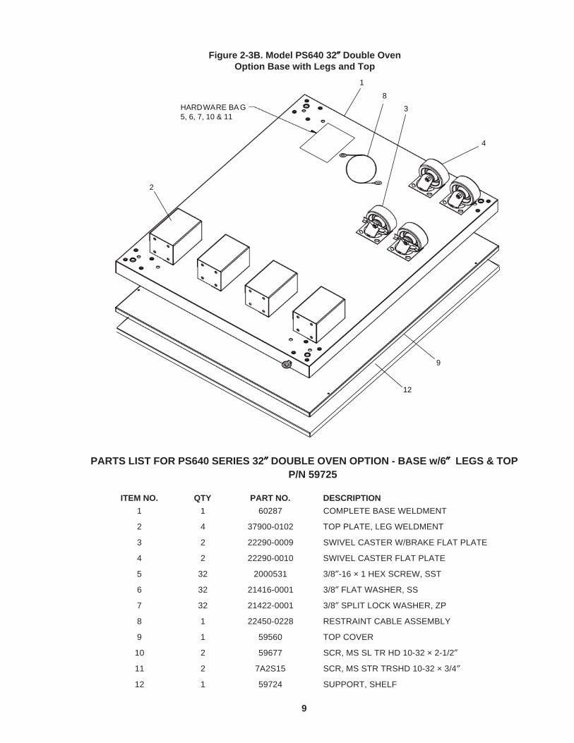
PARTS LIST FOR PS640 SERIES 32″″″″″ DOUBLE OVEN OPTION - BASE w/6″″″″″ LEGS & TOPP/N 59725
HARDWARE BA G 5, 6, 7, 10 & 11
1
2
3
4
9
8
12
Figure 2-3B. Model PS640 32″″″″″ Double OvenOption Base with Legs and Top
9

ITEM NO. QTY PART NO. DESCRIPTION1 1 61126 COMPLETE BASE WELDMENT
2 4 45209 QUAD OUTRIGGER WELDMENT
3 2 22290-0009 SWIVEL CASTER, W/BRAKE FLAT PLATE
4 2 22290-0010 SWIVEL CASTER, FLAT PLATE
5 4 45206 INSERT,QUAD ADJUSTMENT FOOT
6 4 45205 SPACER,QUAD CASTER
7 32 A27727 3/83 -16x1-1/4 HEX BOLT
8 32 A21924 3/83 FLAT WASHER, SS
9 32 21422-0001 3/83 SPLIT LOCK WASHER, ZP
10 16 21172-0004 3/83 -16 NYLON INSULATED LOCKNUT, ZC
11 8 2001048 1/23 -13 x 1-3/8 18-8 HEX CAPSCREW
12 8 A27750 1/23 18-8 FLAT WASHER
13 8 21422-0016 1/23 18-8 LOCK WASHER
14 2 59677 SCR, MS SL TR HD 10-32X2-1/2
15 1 22450-0228 RESTRAINT CABLE ASSEMBLY
16 1 61125 TOP COVER
17 2 7A2S15 SCR, MS STR TRSHD 10-32X3/4″
PARTS LIST FOR PS640 SERIES 24″″″″″ TRIPLE OVEN OPTION - BASE w/CASTERS & TOPP/N 61458
HARDWARE BAG7, 8, 9, 10, 11, 12,13, 14, & 17
1
2
3
4
16
15
6
5
Figure 2-4A. Model PS640 24″″″″″ Triple OvenOption Base with Outriggers and Top
10

ITEM NO. QTY PART NO. DESCRIPTION1 1 60287 COMPLETE BASE WELDMENT
2 4 45209 QUAD OUTRIGGER WELDMENT
3 2 22290-0009 SWIVEL CASTER, W/BRAKE FLAT PLATE
4 2 22290-0010 SWIVEL CASTER, FLAT PLATE
5 4 45206 INSERT,QUAD ADJUSTMENT FOOT
6 4 45205 SPACER,QUAD CASTER
7 32 A27727 3/83 -16x1-1/4 HEX BOLT
8 32 A21924 3/83 FLAT WASHER, SS
9 32 21422-0001 3/83 SPLIT LOCK WASHER, ZP
10 16 21172-0004 3/83 -16 NYLON INSULATED LOCKNUT, ZC
11 8 2001048 1/23 -13 x 1-3/8 18-8 HEX CAPSCREW
12 8 A27750 1/23 18-8 FLAT WASHER
13 8 21422-0016 1/23 18-8 LOCK WASHER
14 2 59677 SCR, MS SL TR HD 10-32X2-1/2
15 1 22450-0228 RESTRAINT CABLE ASSEMBLY
16 1 59560 TOP COVER
17 2 7A2S15 SCR, MS STR TRSHD 10-32X3/4″
PARTS LIST FOR PS640 SERIES 32″″″″″ TRIPLE OVEN OPTION - BASE w/CASTERS & TOPP/N 59726
HARDWARE BAG7, 8, 9, 10, 11, 12,13, 14, & 17
1
2
3
4
16
15
6
5
Figure 2-4B. Model PS640 32″″″″″ Triple OvenOption Base with Outriggers and Top
11

V. KEY SPARE PARTS KIT # 60904 – Available separately. See Figure 4-8. This Page Updated 8-20-2015
KEY SPARE PARTS PS640 GAS
ITEM QTY. P/N DESCRIPTION
1 1 67050 Digital Display, Programmed2 1 58920 Motor, Conveyor Drive3 1 66759 Conveyor Control Board4 1 70884 Inverter, Programmed5 1 69533 Power Supply6 1 33984 Kit, Thermocouple7 1 65061 Fan Cooling Control (97525 until 7/2011)
8 1 51399 Fan Cooling Rear9 1 60598 Air Switch10 1 57288 Motor, Blower11 1 62285 Ignition Module12 1 60679 Assy, Valve Gas Modulating13 1 60671 Board, Signal Cond. 0-15VDC14 1 33983 High Limit Control Module,240V15 2 32108 Transformer,240Vp:24Vs16 1 67052 PLC ModuIe, Programmed17 1 58668 Thermocouple Module18 1 58669 Current Module19 1 60185 PhotoCell20 2 59132 Relay, DPDT 24V Coil21 1 59668 Belt, Blower
22 1 71037 Ignitor, Single Rod23 1 50240 Ignition Cable, 25″24 1 68371 Bearing, PB 5/8 Bore
Figure 4-8. Key Spare Parts
1 2 3 4 5
15
12
10
16, 17, 18
1920 21
22 23 24


SECTION 5 - WIRING DIAGRAM
Mid
dle
by-
Mar
shal
l Mo
del
Nu
mb
er G
208-
240
Vo
lt 5
0/60
Hz,
1 P
has
e
35
5932
4 R
ev.
E

36
NOTES

37
NOTES

Middleby Cooking Systems Group • 1400 Toastmaster Drive • Elgin, IL 60120 • USA • (847)741-3300 • FAX (847) 429-7508
www.middleby-marshall.com www.middleby.com
Middleby is proud to support the Commercial Food EquipmentService Association (CFESA). We recognize and applaudCFESA's ongoing efforts to improve the quality of technicalservice in the industry.
WARNINGImproper installation, adjustment, alteration, service or maintenance
can cause property damage, injury or death. Read the installation,operating and maintenance instructions thoroughly before
installing or servicing this equipment.
NOTICEDuring the warranty period, ALL parts replacement and servicing should be performed
by your Middleby Marshall Authorized Service Agent. Service that is performed byparties other than your Middleby Marshall Authorized Service Agent may void your
warranty.
NOTICEUsing any parts other than genuine Middleby Marshall factory manufactured parts
relieves the manufacturer of all warranty and liability.
NOTICEMiddleby Marshall reserves the right to change specifications at any time.