single-stub impedance matching - w1ghz.org … practice, it works fine for a moderate vswr, perhaps...
TRANSCRIPT
Single-Stub Impedance Matching
Paul Wade W1GHZ ©2016
In theory, you can match any impedance with a single transmission line stub in the right place –
a series transmission line and a stub. In practice, it works fine for a moderate VSWR, perhaps
3:1 or less. For serious mismatches, the losses in the line and stub can be significant and burn up
a lot of power.
Stub matching can be easy and effective – I have a couple of examples to demonstrate.
We first moved to Vermont in December. Sometime that winter we got a couple of warmer
days, so I dug out a small rover tower. W1AIM and I lashed it to the deck support with ratchet
straps from the pickup, then stuck a couple of small rover beams for 6 and 2 meters on top.
The 6-meter beam, an old 3-element Cushcraft, showed some VWSR, enough to make the
transceiver shut down. We weren’t going out in the cold to fiddle with it, so it had to be matched
at the shack end. A Tee connector allows adding a short length of cable as a stub, and changing
cables to find the right stub length. Most of the test equipment wasn’t unpacked yet, so I had to
rely on the transceiver VSWR display, testing with the power turned down.
The first attempt, with a short stub where the cable went throught the wall, made the VSWR
worse. Moving to the other end of the jumper, at the transceiver, also made things worse. Since
the jumper, 4 or 5 feet, is roughly ¼ wavelength long, the right distance should be somewhere
near halfway in between. I had a number of short cables with various connectors from the old
QTH, so I could try different lengths with some adapters. A few tries with different cable
lengths found a promising location, and various short stubs started to bring the VSWR down.
Then it was just a matter of fiddling until the VSWR was low enough to run the transceiver at
full power. The final adjustment was to find or cut RG-8 size coax to the right lengths – I didn’t
want to run RG-58 at 100 watts.
VHF Dummy Load
Some time ago, I acquired a large
dummy load capable of legal limit
power, but hadn’t needed it. Recently, I
was working on some solid-state
amplifiers capable of more power than
my other dummy load, so I tested the
big one. It looked fine at HF, OK at 6
meters, but not so good at higher
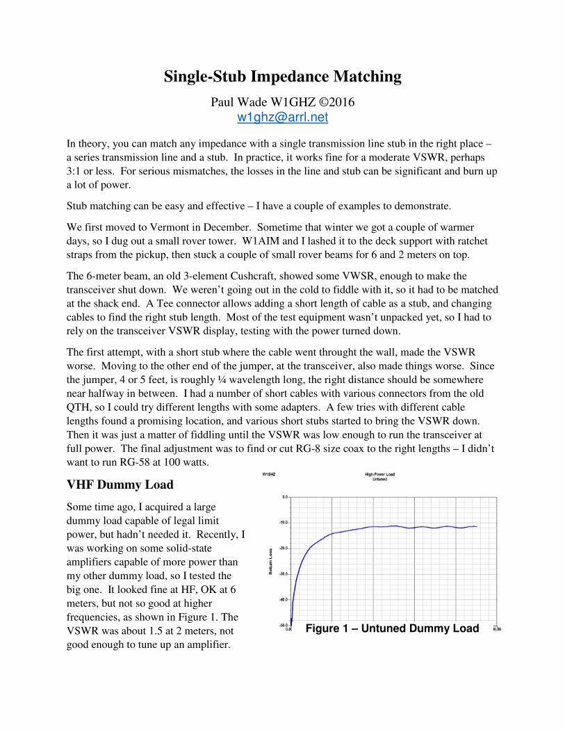
frequencies, as shown in Figure 1. The
VSWR was about 1.5 at 2 meters, not
good enough to tune up an amplifier.
Figure 1 – Untuned Dummy Load
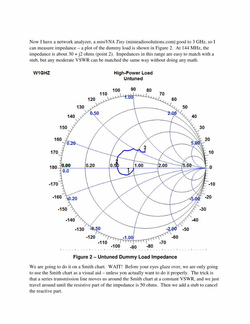
Now I have a network analyzer, a miniVNA Tiny (miniradiosolutions.com) good to 3 GHz, so I
can measure impedance – a plot of the dummy load is shown in Figure 2. At 144 MHz, the
impedance is about 30 + j2 ohms (point 2). Impedances in this range are easy to match with a
stub, but any moderate VSWR can be matched the same way without doing any math.
Figure 2 – Untuned Dummy Load Impedance
We are going to do it on a Smith chart. WAIT! Before your eyes glaze over, we are only going
to use the Smith chart as a visual aid – unless you actually want to do it properly. The trick is
that a series transmission line moves us around the Smith chart at a constant VSWR, and we just
travel around until the resistive part of the impedance is 50 ohms. Then we add a stub to cancel
the reactive part.
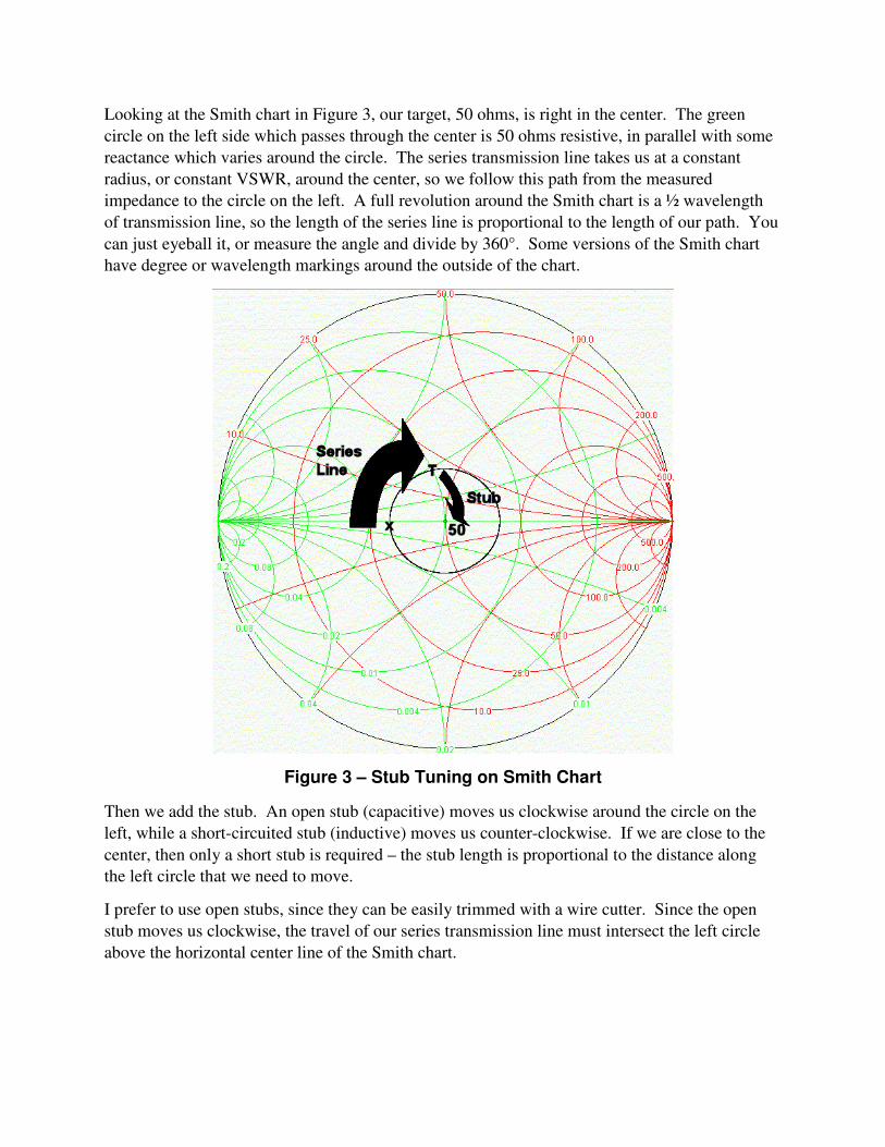
Looking at the Smith chart in Figure 3, our target, 50 ohms, is right in the center. The green
circle on the left side which passes through the center is 50 ohms resistive, in parallel with some
reactance which varies around the circle. The series transmission line takes us at a constant
radius, or constant VSWR, around the center, so we follow this path from the measured
impedance to the circle on the left. A full revolution around the Smith chart is a ½ wavelength
of transmission line, so the length of the series line is proportional to the length of our path. You
can just eyeball it, or measure the angle and divide by 360°. Some versions of the Smith chart
have degree or wavelength markings around the outside of the chart.
Figure 3 – Stub Tuning on Smith Chart
Then we add the stub. An open stub (capacitive) moves us clockwise around the circle on the
left, while a short-circuited stub (inductive) moves us counter-clockwise. If we are close to the
center, then only a short stub is required – the stub length is proportional to the distance along
the left circle that we need to move.
I prefer to use open stubs, since they can be easily trimmed with a wire cutter. Since the open
stub moves us clockwise, the travel of our series transmission line must intersect the left circle
above the horizontal center line of the Smith chart.
For my dummy load, the matching scheme on the Smith chart is shown in Figure 3 – a short
series transmission line, with a stub moving clockwise to the 50 ohm center. Using the degree
scale on the Smith chart in Figure 2 and estimating with the actual impedance, the series line is
about 0.085 wavelengths long, or roughly 7 inches in air, and shorter in coax.
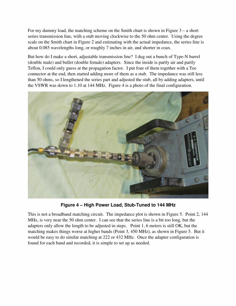
But how do I make a short, adjustable transmission line? I dug out a bunch of Type-N barrel
(double male) and bullet (double female) adapters. Since the inside is partly air and partly
Teflon, I could only guess at the propagation factor. I put four of them together with a Tee
connector at the end, then started adding more of them as a stub. The impedance was still less
than 50 ohms, so I lengthened the series part and adjusted the stub, all by adding adapters, until
the VSWR was down to 1.10 at 144 MHz. Figure 4 is a photo of the final configuration.
Figure 4 – High Power Load, Stub-Tuned to 144 MHz
This is not a broadband matching circuit. The impedance plot is shown in Figure 5. Point 2, 144
MHz, is very near the 50 ohm center. I can see that the series line is a bit too long, but the
adapters only allow the length to be adjusted in steps. Point 1, 6 meters is still OK, but the
matching makes things worse at higher bands (Point 3, 450 MHz), as shown in Figure 5. But it
would be easy to do similar matching at 222 or 432 MHz. Once the adapter configuration is
found for each band and recorded, it is simple to set up as needed.

Figure 5 – Impedance of Dummy Load with Stub Tuning for 144 MHz
Microwaves
Stub tuning is a technique you can use at any frequency. At lower microwave frequencies, SMA
connectors and adapters could be used. On microstrip circuits, snowflaking is using the same
technique, but losses are often lower if several small stubs are used rather than a single one.
In waveguide, there is an implement called a slide-screw tuner, where a probe on a carriage
slides along a slot in the waveguide to find the best match. An example is shown in Figure 6.
The probe acts like a capacitive stub whose length is adjusted by the micrometer, and sliding the
carriage adjust the length of the series line. Operation is simple – the probe is inserted a small
amount, then slid back and forth for best VSWR. Then the probe depth is adjusted and moved,
repeating until the VSWR is good enough.
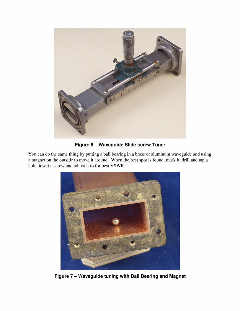
Figure 6 – Waveguide Slide-screw Tuner
You can do the same thing by putting a ball bearing in a brass or aluminum waveguide and using
a magnet on the outside to move it around. When the best spot is found, mark it, drill and tap a
hole, insert a screw and adjust it to for best VSWR.
Figure 7 – Waveguide tuning with Ball Bearing and Magnet