thin lenses - union collegeminerva.union.edu/labrakes/thin lenses.pdfthin lenses types of lenses ......
TRANSCRIPT

Thin Lenses Types of Lenses: Converging and Diverging Lenses
Thin lenses are devices whose centers are very thin. Images are formed of an object
placed in front of these lenses as a result of the refraction of light between the lens and the surrounding medium. Converging (or double convex) lenses take an initially parallel beam of light and bend that light toward a common point called the focal length of the lens, whereas a diverging (double concave) lenses take an initially parallel beam of light and bend that light away from the focal length of the lens. Converging lenses are fatter at their center and thinner at their edges while diverging lenses are thinner at their center and fatter at their edges. Examples of thin converging and diverging lenses are shown in Figure 1.
We will use the ideas of refraction to trace the path of a ray though both a converging
and diverging lens. Then we will develop a system to trace the rays emanating from an object passing through a lens and use these ray tracings to manually locate the image of the object. Lastly, from the geometry of the system, we will develop mathematical formulas (called the thin lens equations) to actually determine the location of the image formed of an object. There are two types of lenses that we will be studying. Converging (or double convex) lenses are fatter at their center and thinner at their edges. Converging lenses take an initially parallel beam of light and focuses that light (after refracting the light on the front and back surfaces of the lens) to a common point called the focal point of the lens.
The image of an object is formed by light being refracted on the front and back surfaces of the lens. To see how refraction bends the light ray, consider the upper half of a double convex lens as shown in Figure 2 below. A ray of light is incident in air (of refractive index nair ) on the left surface of the lens assumed for this example, to be made out of glass (index of refraction nglass ) at an angle θ with respect to the normal to the surface (the dashed line). Since the glass lens has a higher refractive index than that of the surrounding air, the ray of light bends towards the normal in the material. The light ray will then travel in a straight line
Figure 1: Cartoon picture of thin converging and diverging lenses. Light entering on the left surface is refractive by the lens and the light emerges toward (converging) or away from (diverging) a common point called the focal point. https://www.math.ubc.ca/~cass/courses/m309-01a/chu/MirrorsLenses/lenses.htm

in the lens until it reaches the right side surface of the lens. Again, drawing the normal to the surface (the dashed line) and using the fact that the light is entering air (a lower refractive index material) from the glass lens, the light bends away from the normal to the surface. This light ray then passes through a point called the focal point of the lens defined from the center of the lens and labeled as fc in Figure 2.
As a more quantitative example, consider the following scenario shown by Figure 3. An equilateral triangle shaped piece of glass with index of refraction (nglass = 1.5 ) is surrounded on all sides by air (nair = 1.0 ). A beam of light is incident from the left and strikes the glass surface at an angle θ = 300 of with respect to the normal as shown below. What is the angle of refraction of the light with respect to the normal to the surface? Applying the law of refraction we have
nair sinθair = nglass sinθglass →θglass = sin−1 nair
nglasssinθair
⎛
⎝⎜⎞
⎠⎟= sin−1 1.0
1.5sin30⎛
⎝⎜⎞⎠⎟ = 19.5
0 . Next we
could ask at what angle (with respect to the normal) will the light ray will emerge from the right side of the equilateral triangle? To answer this we need to know at what angle the light ray strikes the glass/air surface with respect to the normal in the glass. To do this we need start with the left side of the triangle and work our way around to the right side of the triangle. On the left side, the light makes an angle of 19.50 with respect to the normal to the surface and since the normal is by definition perpendicular to the surface, the upper angle is thus 70.50 . Considering the upper triangle and knowing that the apex angle is 600 (since we have an equilateral triangle), we can find the angle the light ray makes between the glass surface and the normal on the right side. Calling this angle φ we have, 1800 = 70.50 + 600 +φ →φ = 49.50
. Again, since the normal is perpendicular to the surface, we can find the angle the light makes with respect to the normal to the surface and this is 40.50 . Applying the law of refraction on the right side glass/air interface we can determine the angle the light ray makes after it exits the piece of glass. We find
nglass sinθglass = nair sinθair →θair = sin−1 nglass
nairsinθglass
⎛⎝⎜
⎞⎠⎟= sin−1 1.5
1.0sin40.5⎛
⎝⎜⎞⎠⎟ = 76.9
0 .
θ
fc Figure 2: A schematic of a converging lens showing a ray of light incident on the left surface of the lens. This ray is bent toward the normal to the surface upon entering the glass lens from air and when it strikes the right surface, the light ray bends away from the normal to the surface upon entering the air from the glass.

As one last example, let’s take Figure 3, copy it, and then paste rotate the figure by 1800 . Next we’ll place the original figure and it’s image on top of each other as seen in Figure 4. Notice that this approximates a double convex or converging lens. Where the two rays from the right side of the lens cross, as measured from the center of the lens, is defined as the focal length of the lens, fc .
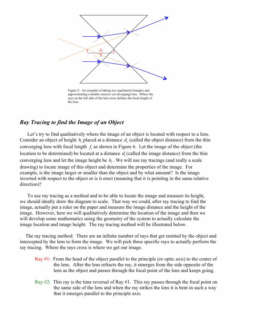
We can do the exact same procedure to model a diverging lens. Consider Figure 5 in which we take our equilateral triangle and stack the two apex angles together. Notice here that the two rays that emerge from the right side of the lens never cross. This will be important later when we talk about the types of images that can be formed from a lens. Here suffice it to say that we can still define the focal length of the lens. We take each of the two rays that emerge from the right hand side and extend them backwards along the arrow. Where these two extensions cross, measured with respect to the center of the lens, defines the focal length of the diverging lens fD .
19.50
70.50
600
300
40.50 49.50
76.90
Figure 3: Example of applying the law of refraction to an equilateral triangle shaped piece of glass surrounded by air.
nglass = 1.5 nair = 1.0
Figure 4: An example of taking two equilateral triangles and approximating a double convex (or converging) lens. Where the rays on the right side of the lens cross defines the focal length of the lens.
fc
Ray Tracing to find the Image of an Object
Let’s try to find qualitatively where the image of an object is located with respect to a lens. Consider an object of height ho placed at a distance do (called the object distance) from the thin converging lens with focal length fc as shown in Figure 6. Let the image of the object (the location to be determined) be located at a distance di (called the image distance) from the thin converging lens and let the image height be hi . We will use ray tracings (and really a scale drawing) to locate image of this object and determine the properties of the image. For example, is the image larger or smaller than the object and by what amount? Is the image inverted with respect to the object or is it erect (meaning that it is pointing in the same relative direction)?
To use ray tracing as a method and to be able to locate the image and measure its height,
we should ideally draw the diagram to scale. That way we could, after ray tracing to find the image, actually put a ruler on the paper and measure the image distance and the height of the image. However, here we will qualitatively determine the location of the image and then we will develop some mathematics using the geometry of the system to actually calculate the image location and image height. The ray tracing method will be illustrated below.
The ray tracing method: There are an infinite number of rays that get emitted by the object and
intercepted by the lens to form the image. We will pick three specific rays to actually perform the ray tracing. Where the rays cross is where we get our image.
Ray #1: From the head of the object parallel to the principle (or optic axis) to the center of
the lens. After the lens refracts the ray, it emerges from the side opposite of the lens as the object and passes through the focal point of the lens and keeps going.
Ray #2: This ray is the time reversal of Ray #1. This ray passes through the focal point on
the same side of the lens and when the ray strikes the lens it is bent in such a way that it emerges parallel to the principle axis.
Figure 5: An example of taking two equilateral triangles and approximating a double concave (or diverging) lens. Where the rays on the left side of the lens cross defines the focal length of the lens.
fD

Ray #3: This ray originates from the head of the object and heads towards the center of the lens. After the lens refracts the ray it emerges on the right side of the lens parallel to itself.
Drawing all three rays we see that they cross on the opposite side of the lens as the object. This
means that the image can be projected and this gives rise to a real image. The real image is inverted (all real images are inverted with respect to their object) and the overall size of the image would have to be measured. Here it’s too tough to tell just by looking at the image.
We can use the same procedure to determine the image location of an object near a thin
diverging lens. Again, consider an object of height ho placed at a distance from a thin diverging lens with focal length fD as shown in Figure 7. Let the image of the object (the location to be determined) be located at a distance di (called the image distance) from the thin diverging lens and let the image height be hi . Again we will use ray tracings (and really a scale drawing) to locate image of this object and determine the properties of the image. The three rays that we will draw are given similarly to the three rays above. Here we have to be careful since the diverging ray bends the beam of light away from the focal point of the lens rather than towards the focal point as in the case of the converging lens.
Ray #1: From the head of the object parallel to the principle (or optic axis) to the center of
the lens. After the lens refracts the ray, it diverges away from the focal point on the side of the lens as the object and keeps going.
Ray #2: This ray is again the time reversal of Ray #1. This ray passes heads toward the
focal point on the opposite side of the lens as the object and when the ray strikes the lens it is bent in such a way that it emerges parallel to the principle axis.
Ray #3: This ray originates from the head of the object and heads towards the center of the
lens. After the lens refracts the ray it emerges on the right side of the lens parallel to itself.
do
ho
di
hi
fc fc
Figure 6: An example of ray tracing to determine the image of an object in a converging lens.

Here we see that rays that emerge on the opposite side of the lens from the object will never
intersect with one another. Thus there is no place on the right side of the lens that a real image will be produced. But to our eyes on the right side of the lens, Ray #1 would appear to have originated at the focal point of the lens on the same side of the lens as the object. And, to our eyes on the right side of the lens, Ray #2 would appear to have come from straight back through the lens. Tracing these rays back (the dashed lines on the left side of the lens) we see that they intersect. This intersection is where the image is located. But the rays do not actually originate from this location (they are passing out of the lens on the right hand side). Therefore the image is not a real image, but rather a virtual image. The light rays are not really there. Here the image too is smaller than the object. In addition the object is oriented in the same direction as the object. We call the orientation of this image erect. These are main properties of a diverging lens, namely it will always produce a virtual image and it will always make an image that is smaller than the original object.
The Thin Lens Equation
Using Ray tracings provides for a convenient tool to locate the approximate location of the image of an object. Again, if we were to draw the diagram to scale then we could measure the location of the image and the image height with a ruler. In general we don’t usually draw the diagram to scale, but we’d still like to know where the image of the object is located and what its properties are. However, what we’d really like is a method to mathematically calculate the location of the image and determine its properties. To determine a mathematical formula to locate an image of an object for a given lens we will use the geometry of the system. This is the field of geometric optics.
Converging Lenses
Consider a converging lens situated with its center on the principle axis as is shown in Figure 6
with an object of height ho located at a distance do from the lens. The real image, by ray tracing, is located at a distance di on the opposite of the lens from the object and the image has a height hi . We’d like to determine the image height hi in terms of the object distance, do say, the focal length of the lens fc and perhaps the object height ho since those are the parameters we can control. In addition we would also like to determine the image location di in terms of some of those same
fD
Figure 7: An example of ray tracing to determine the image of an object in a diverging lens.
hi
di
do
ho fD

parameters, do , ho , and fc . To determine the image height and image location let us examine the geometry of the system shown in Figure 8. Figure 8 is simply Figure 6 with some triangles highlighted in order to utilize the geometry of the system to determine the image height and image location.
Considering the light green shaded triangles above in Figure 8. Defining the vertical angles as
α we can relate the object height ho to the image height hi given the object and image distances do
and di respectively. From the geometry we have tanα = hodo
= hidi
. We define the linear
magnification to be M ≡ hiho
= dido
so that the image height is hi = M × ho . Here, if M ≥1 than the
image height is greater than the object height (hi ≥ ho ) and we say the image is magnified. If M <1 then the image height is smaller than the object height (hi < ho ) and we say that the image has been de-magnified.
The problem with the magnification equation is that in order to determine the image height hi
we need to know where the image is located, di . To determine the image location, consider Figure 9 below and examine the pink triangles defining the vertical angles to be β we have
tanβ = hofc − do
= hifc
. We can express the ratio of the image to the object heights as the
magnification and further express this in terms of the object and image distances. Doing this we
have hofc − do
= hifc→ M = hi
ho= dido
= fcfc − do
. The thin lens equation for converging lenses is
di = dofc
fc − do
⎛⎝⎜
⎞⎠⎟
and this allows us, knowing the focal length of the lens fc and the object distance
do to determine the image distance di . Then armed with the image distance we can determine the image height through the magnification. However we rarely see the thin lens equation given in this form. Let us rearrange this equation into a more compact and perhaps useful formula. Taking the
formuladi = dofc
fc − do
⎛⎝⎜
⎞⎠⎟
, cross multiply and expand out the terms in parentheses. We have
do
ho
di
hi
fc fc
Figure 8: Geometry of a converging lens system to determine the image height.
α α
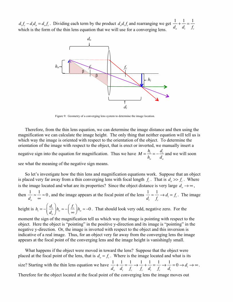
di fc − dido = do fc . Dividing each term by the product dodi fc and rearranging we get 1do
+ 1di
= 1fcwhich is the form of the thin lens equation that we will use for a converging lens.
Therefore, from the thin lens equation, we can determine the image distance and then using the
magnification we can calculate the image height. The only thing that neither equation will tell us is which way the image is oriented with respect to the orientation of the object. To determine the orientation of the image with respect to the object, that is erect or inverted, we manually insert a
negative sign into the equation for magnification. Thus we have M = hiho
= − dido
and we will soon
see what the meaning of the negative sign means. So let’s investigate how the thin lens and magnification equations work. Suppose that an object
is placed very far away from a thin converging lens with focal length fc . That is do >> fc . Where is the image located and what are its properties? Since the object distance is very large do →∞ ,
then 1do
≈ 1∞
≈ 0 , and the image appears at the focal point of the lens 1di
≈ 1fc→ di = fc . The image
height is hi = − dido
⎛⎝⎜
⎞⎠⎟ho ≈ − fc
∞⎛⎝⎜
⎞⎠⎟ ho ≈ −0 . That should look very odd, negative zero. For the
moment the sign of the magnification tell us which way the image is pointing with respect to the object. Here the object is “pointing” in the positive y-direction and its image is “pointing” in the negative y-direction. Or, the image is inverted with respect to the object and this inversion is indicative of a real image. Thus, for an object very far away from the converging lens the image appears at the focal point of the converging lens and the image height is vanishingly small.
What happens if the object were moved in toward the lens? Suppose that the object were
placed at the focal point of the lens, that is do = fc . Where is the image located and what is its
size? Starting with the thin lens equation we have 1do
+ 1di
= 1fc→ 1
fc+ 1di
= 1fc→ 1
di= 0→ di →∞ .
Therefore for the object located at the focal point of the converging lens the image moves out
do
ho
di
hi
fc fc
Figure 9: Geometry of a converging lens system to determine the image location.
β β

towards infinity. The image height is given by the magnification equation and we have
hi = − dido
⎛⎝⎜
⎞⎠⎟ho = − ∞
fc
⎛⎝⎜
⎞⎠⎟ho →−∞ . The image is a real image and it is very large!
Let’s recap. For an object placed very far away from the converging lens the image is real,
inverted, and very small. As the object is moved in towards the focal point of the lens, the image moves away from the focal point on the opposite side of the lens as the object, remains real and inverted and grows in size. By the way, you should really check that these results are also obtained by performing a ray tracing.
Of course nothing prohibits us from placing the object closer to the lens. What happens if we
put the object inside of the focal length (do < fc ) of the converging lens? To locate the image use
the thin lens equation and we find: 1do
+ 1di
= 1fc→ 1
di= 1fc− 1do < fc( ) . For any given focal length
fc , the fact that do < fc means that 1do < fc( ) >
1fc
. This makes the image distance a negative
number! We cannot calculate a value for the image distance since we do not actually know any of the numbers involved, but it is negative nonetheless and it is probably very large since 1fc− 1do < fc( ) is a small number and therefore the image distance di is probably large. What does
the magnification equation tell us? From the magnification equation we have
hi = − dido
⎛⎝⎜
⎞⎠⎟ho = − −di
do < fc
⎛⎝⎜
⎞⎠⎟ho which is a large positive number. This means that the image is very
large in size and the positive sign means that the image is actually erect, or pointing in the same direction as the object. The negative image distance tells us about the location of the image with respect to the object. The negative image distance means that the image is on the same side of the lens as the object, or a virtual image! This particular setup is the classic magnifying glass.
Can we verify this by a ray tracing? The ray tracing is shown in Figure 10 below. Here Ray #1
is as usual however, if you trace Ray #2 through the focal point on the same side of the lens as the object, the ray would never hit the lens. So to fix this, we assume that Ray #2 originated at the focal point and goes through the head of the object. This ray does not obviously strike the lens, but we extend the plane of the lens upward and when Ray #2 strikes the extension of the plane of the lens it emerges parallel to the principle axis. Ray #3 is as usual. Where the rays cross on the opposite side of the lens from the object is where the real image is formed. It is obvious that these rays will never cross anywhere on the right side of the lens. But, we can extend these rays back since our eyes perceive them to travel in straight lines, we see that they will cross on the same side of the lens as the object. Since the extensions of these rays are not really crossing at the location of the image, the converging lens creates a virtual image of the object when the object is placed inside of the focal length of the lens. In order to see the image of the object, one has to stand on the right side of the lens and look though the lens at the object. The virtual image will be easily seen and you should notice if you try this that the image is oriented in the same direction as the object and it is considerably larger.

Example 1: An example of a converging lens. Suppose that you have a converging lens with a focal length fc = 24cm . An object 1cm in height is placed at a location of do = 45cm to the left of the converging lens. Where will the image be located and what are the image properties? Solution: Starting with the thin lens equation we can determine the location of the image. We have: 1do
+ 1di
= 1fc→ 1
di= 1fc− 1do
= 124cm
− 145cm
→ di = 51.4cm .
Therefore since the image distance is positive, the image is located to the right of the lens on the opposite side of the lens as the object at a distance of di = 51.4cm . Thus the image is a real image. To determine the image height we use the magnification equation. We have:
hi = − dido
⎛⎝⎜
⎞⎠⎟ho = − 51.4cm
24cm⎛⎝⎜
⎞⎠⎟ ×1cm = −2.2cm .
Thus the image is magnified by 2.2 times and the image is therefore 2.2cmtall. The negative sign tells us that the image is inverted with respect to the object, indicative of a real image.
do
ho
di
hi
fc fc
Figure 10: Ray tracing for an object inside of the focal point of the converging lens. This is the classic magnifying glass.

Example 2: Suppose that you have the following situation in which you have a series of colored lights placed to the left of a converging lens, where the violet light is closer to the lens than the red light as shown below. What is the order of the colors in the image and if the focal length of the lens isfc = 20cm and the violet light is located a distance d0 = 36cm to the left of
the lens (as shown in the Figure 11 below), what is the lateral magnification
defined by M = − LiLo
? Assume that the object’s length is L0 = 5cm .
Solution: Let’s take the first and last of the colored lights and determine where the image of each is located. For the violet light using the thin lens equation we have1doV
+ 1diV
= 1fc→ diV = 1
fc− 1doV
⎛⎝⎜
⎞⎠⎟
−1
= 120cm
− 136cm
⎛⎝⎜
⎞⎠⎟−1
= 45cmwhile for
the red light, 1doR
+ 1diR
= 1fc→ di1 =
1fc− 1doR
⎛⎝⎜
⎞⎠⎟
−1
= 120cm
− 136cm + 5cm
⎛⎝⎜
⎞⎠⎟−1
= 39cm
Thus the image of the line of colored lights is real and the order of the colors is . The magnification using the definition given is
M = − LiLo
= − 45cm − 39cm5cm
⎛⎝⎜
⎞⎠⎟ = −1.2 and the image of the lights is drawn on
Figure 11 above.
Diverging Lenses In the case that we have a diverging lens, where is the location and what are the properties of
the image of an object placed in front of the diverging lens? To answer these questions we return to Figure 7 and using the geometry of the system proceed in an analogous manner to the converging lens to develop a thin lens and magnification equation for diverging lenses. Consider Figure 12 below for a diverging lens and again let us draw a few triangles in order to develop an equation to determine the image height for a given object height and diverging lens. Consider the
two purple triangles below and using the angle α we have from the geometry tanα = hodo
= hidi
.
Again we define the linear magnification to be M ≡ hiho
= − dido
with a minus sign manually inserted
so that the image height is hi = M × ho . Here, if M ≥1 than the image height is greater than the object height (hi ≥ ho ) and we say the image is magnified. If M <1 then the image height is
fc fc
Figure 11: Example of magnification of a line of colored lights.
object image

smaller than the object height ( hi < ho ) and we say that the image has been de-magnified. For a diverging lens the image will always be de-magnified, meaning M <1 .
The problem with the magnification equation is that in order to determine the image height hi
we need to know where the image is located, di . To determine the image location, consider Figure 13 below and examine the two green triangles defined by the angle β . We have
tanβ = hifD − di
= hofD
. We can express the ratio of the image to the object heights as the
magnification and further express this in terms of the object and image distances. Doing this we
have hifD − di
= hofd→ M = hi
ho= dido
= fD − difD
. The thin lens equation for diverging lenses is
di = dofD − difD
⎛⎝⎜
⎞⎠⎟
and this allows us, knowing the focal length of the lens fD and the object distance
do to determine the image distance di . Then armed with the image distance we can determine the image height through the magnification. However again we rarely see the thin lens equation given in this form. Let us rearrange this equation into a more compact and perhaps useful formula.
Taking the formuladi = dofD − difD
⎛⎝⎜
⎞⎠⎟
, cross multiply and expand out the terms in parentheses. We
have di fD = do fD − dido . Dividing each term by the product dodi fc and rearranging we get 1do
− 1di
= − 1fD
which is a form of the thin lens equation that we could use for a diverging lens.
Figure 12: Geometry of a diverging lens system to determine the image height.
hi
di
do
ho fD α

Sign Conventions for Thin Lenses
However, now we have two thin lens equations; one for converging lenses 1do
+ 1di
= 1fc
and one
for diverging lenses 1do
− 1di
= − 1fD
. What we’d really like is a single thin lens equation. By
convention we use one thin lens equation and adopt a set of sign conventions for object and image distances and focal lengths of lenses.
The thin lens equation that we’ll use is given as: 1do
+ 1di
= 1f
and the magnification equation is
M ≡ hiho
= − dido
. In order to use these two equations we need a set of sign conventions. The sign
conventions are given below. Sign Conventions The focal length of a converging lens is defined to be positive, that is fc > 0 . The focal length of a diverging lens is defined to be negative, that is fD < 0 . The object distance do is positive for all applications we will encounter. The image distance di is positive for real images and negative for virtual images.
Figure 13: Geometry of a diverging lens system to determine the image location.
hi
di
do
ho fD β
Example 3: Suppose that we have a diverging lens with a focal length of fd = −20cm . An object of height ho = 2cm is placed to the left of the
diverging lens at a distance of do = 17cm , where is the image of this object and what is the image height?
Solution: To determine the image distance we use the thin lens equation. We have 1fD
= 1do
+ 1di
→ di =1fD
− 1dov
⎛⎝⎜
⎞⎠⎟
−1
= − 120cm
− 117cm
⎛⎝⎜
⎞⎠⎟−1
= −9.2cm
or 9.2cm to the left of the diverging lens indicating a virtual image. The image height is
M = hiho
= − dido
→ hi = − dido
⎛⎝⎜
⎞⎠⎟h0 = −
−9.2cm( )17cm
⎛⎝⎜
⎞⎠⎟× 2cm = 1.1cm .
The image is reduced in size and is oriented in the same direction as the original object.
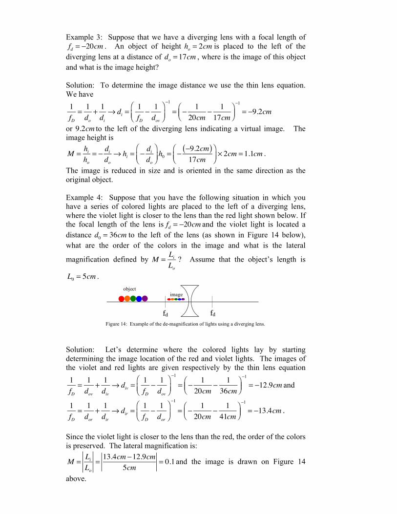
Example 4: Suppose that you have the following situation in which you have a series of colored lights are placed to the left of a diverging lens, where the violet light is closer to the lens than the red light shown below. If the focal length of the lens is fd = −20cm and the violet light is located a distance d0 = 36cm to the left of the lens (as shown in Figure 14 below), what are the order of the colors in the image and what is the lateral
magnification defined by M = LiLo
? Assume that the object’s length is
L0 = 5cm . Solution: Let’s determine where the colored lights lay by starting determining the image location of the red and violet lights. The images of the violet and red lights are given respectively by the thin lens equation1fD
= 1dov
+ 1div
→ div =1fD
− 1dov
⎛⎝⎜
⎞⎠⎟
−1
= − 120cm
− 136cm
⎛⎝⎜
⎞⎠⎟−1
= −12.9cm and
1fD
= 1dor
+ 1dir
→ dir =1fD
− 1dor
⎛⎝⎜
⎞⎠⎟
−1
= − 120cm
− 141cm
⎛⎝⎜
⎞⎠⎟−1
= −13.4cm .
Since the violet light is closer to the lens than the red, the order of the colors is preserved. The lateral magnification is:
M = LiLo
= 13.4cm −12.9cm5cm
= 0.1 and the image is drawn on Figure 14
above.
fd fd Figure 14: Example of the de-magnification of lights using a diverging lens.
object image

Lenses in Combination To investigate combinations of lenses we will apply the thin lens and magnification lenses
multiple times. The basics of lenses in combination are “the image of an object from one lens becomes the object for the second lens.” There is no new physics in putting lenses in combination. So, what we will do is to examine lenses in combination by working some example problems.
Example 5: The Compound Microscope
A two-lens system is constructed from two converging lenses. An object 1cm in height is placed to the left of the first converging lens ( fc1 = 15cm ) at a distance of do = 24cm . The second converging lens ( fc2 = 25.5cm ) is positioned to the right of the first converging lens and at a distance of d = 61cm from the first lens. Where is the location and properties of the final image? Solution: Lens #1: We calculate the image of the object using the first lens. We have
1do1
+ 1di1
= 1fc1
→ 1di1
= 1fc1
− 1do1
→ di1 =1fc1
− 1do1
⎛⎝⎜
⎞⎠⎟
−1
= 115mm
− 124mm
⎛⎝⎜
⎞⎠⎟−1
= 40mm
or 40mm to the right of the first lens. This first image has a height of
M1 =hi1ho
= − di1do1
→ hi1 = − di1do1
⎛⎝⎜
⎞⎠⎟ho = − 40mm
24mm⎛⎝⎜
⎞⎠⎟ ×1cm = −1.67cm using the
magnification equation. The image is real, inverted (the negative sign in the magnification) and 1.67cm times larger. Lens #2: Now the image of this first object becomes the object for the second lens. We’ll use the thin lens equation again with the fact that this object is located at a distance of D = di1 + do2 → do2 = D − di1 = 61mm − 40mm = 21mm from the second lens. The thin lens equation gives us the final image location. It is 1do2
+ 1di2
= 1fc2
→ 1di2
= 1fc2
− 1do2
→ di2 =1fc2
− 1do2
⎛⎝⎜
⎞⎠⎟
−1
= 125.5mm
− 121mm
⎛⎝⎜
⎞⎠⎟−1
= −119mm
or 119mm to the left of the second lens. Here this image is located on the same side of the lens as the object that produced it (namely the image of the original object from the first lens). This final image is therefore a virtual

image and from the magnification we find the final image height,
M 2 =hi2ho2
= hi2hi1
= − di2do2
→ hi2 = − di2do2
⎛⎝⎜
⎞⎠⎟hi1 = − −119mm
21mm⎛⎝⎜
⎞⎠⎟ ×1.67cm = 9.46cm
.
The final image is times the original object and is inverted with respect to the original object. This final image is a virtual image and to see the enlarged virtual image we have to stand on the right side of the lens system and look backwards through the lens (or look to the left). Also, note that this should be expected. The location of the first image falls inside of the focal length of the second lens. Thus, the final image should be virtual and be magnified. This second converging lens is a magnifier and it is used to enlarge the image of the (usually tiny) object. This is the basic working of a compound microscope. Notice that we could put the magnification equations together to get the total magnification hi2ho2
= hi2hi1
= − di2do2
→ hi2 = − di2do2
⎛⎝⎜
⎞⎠⎟hi1 = − di2
do2
⎛⎝⎜
⎞⎠⎟hi1 = − di2
do2
⎛⎝⎜
⎞⎠⎟
− di1do1
⎛⎝⎜
⎞⎠⎟ho = M 2 ×M1ho = Mtotalho
or, Mtotal = M1 ×M 2 a product of the two individual magnifications. This of course could be extended to any number of lenses in combination. A ray diagram “approximately” to scale is shown in Figure 15 below.
di1
di2
D
fc1 fc1 fc2 fc2
Figure 15: Ray diagram for a two converging lens system modeling a compound microscope. To see the enlarged virtual image we look backwards through the lens from right to left.
do1
do2

Example 6: Determining the focal length of a diverging lens using a converging lens
A two-lens system is constructed from a diverging lens of unknown focal length and a known focal length converging lens. An object 1cm in height is placed to the left a diverging lens of unknown focal length ( fD ) at a distance of do1 = 30mm . A converging lens ( fc = 40mm ) is positioned to the right of the diverging lens and at a distance of d = 80mm between the centers of the lens. A real image is produced on a screen to the right of the converging lens at a distance of di2 = 70.4mm . Where is the focal length of the diverging lens? Solution:
Lens #1: Here we use the thin lens equation. So, 1do1
+ 1di1
= 1fD
, but
unfortunately we don’t know where the image di1of the object is in relation to the diverging lens. So, to calculate this image distance of the object in the diverging lens, let’s look at the converging lens in the system. Here we’re going to calculate the location of the object (the diverging lens image) that produced the real image from the converging lens. Lens #2: Applying the thin lens equation to the converging lens we can determine the object distance from the converging lens. We have 1do2
+ 1di2
= 1fc→ do2 =
1fc− 1di2
⎛⎝⎜
⎞⎠⎟
−1
= 140mm
− 170.4mm
⎛⎝⎜
⎞⎠⎟−1
= 92.7mm
to the left of the converging lens. Now we can determine where the image distance is for the diverging lens. Thus the image distance for the diverging lens is do2 = D + di1 → di1 = do2 − D = 92.7mm − 80mm = 12.7mm . Now we that that diverging lenses always produce a virtual image, and thus the image distance is a negative quantity. Thus we have to add a minus sign to di1 = −12.7mm . Now we can determine the focal length of the diverging lens. 1do1
+ 1di1
= 1fD
→ fD = 1do1
+ 1di1
⎛⎝⎜
⎞⎠⎟
−1
= 130mm
− 112.7mm
⎛⎝⎜
⎞⎠⎟−1
= −22mm
As expected the focal length of the diverging lens is negative. A ray tracing is shown in Figure 16 below.
di1
di2
D
fD fd fc fc
Figure 16: Ray diagram for a two converging lens system that includes a diverging and a converging lens. The diverging lens produces a virtual image and the converging lens is used to produce a real image.
do1
do2

The Human Eye
As an application of a two-lens system we examine the human eye. The human eye is essentially a double convex lens that is capable of changing its focal length to accommodate a wide range of visual situations from objects being very far away to objects being right up close to your eye. A cut away view in Figure 17 shows the main components of the human eye. The cornea is the transparent, dome-shaped window covering the front of the eye. It is a powerful refracting surface, providing of the eye’s focusing power. Like the crystal on a watch, it gives us a clear window to
look through. There are no blood vessels in the cornea, and it is normally clear with a shiny surface. The cornea is extremely sensitive - there are more nerve endings in the cornea than
anywhere else in the body and the adult cornea is only about ½ millimeter thick.
The Iris is the colored part of the eye, which helps regulate the amount of light entering the eye
through the pupil (black hole). In bright light, the sphincter contracts, causing the pupil to constrict. The dilator muscle runs radially through the iris, like spokes on a wheel. This muscle
dilates the eye in dim lighting. The iris is flat and divides the front of the eye (anterior chamber) from the back of the eye (posterior chamber). Its color comes from microscopic pigment cells called melanin. The color, texture, and patterns of each person's iris are as unique as a fingerprint.
A cartoon drawing of the cross section of the eye is shown in Figure 18 below.
1. Epithelium (cornea) 2. Stroma (cornea) 3. Descemet's membrane and endothelium (cornea) 4. Anterior chamber 5. Iris 6. Lens 7. Ciliary body 8. Sclera
Figure 17: Cut away view of the human eye showing the basic anatomy, especially the crystalline lens.
http://www.missionforvisionusa.org/anatomy/uploaded_images/GrosASlabMfV-702936.jpg
Figure 18: Cartoon cut away view of the human eye showing the basic anatomy.

The crystalline lens is located just behind the iris. Its purpose is to focus light onto the retina. The nucleus, the innermost part of the lens, is surrounded by softer material called the cortex. The lens is encased in a capsular-like bag and suspended within the eye by tiny delicate fibers called
zonules. In young people, the lens changes shape to adjust for close or distance vision. This is called accommodation. With age, the lens gradually hardens, diminishing the ability to accommodate. Figure 19 gives another cut away view of the crystalline lens.
In a nutshell, the cornea aids in the focusing of light to create an image on the retina by means
of refraction. Often, the shape of the cornea and the eye are not perfect and the image on the retina is out-of-focus. This gives rise to conditions known as refractive errors, or imperfections in the focusing power of the eye. There are three primary types of refractive errors. They are Myopia – or nearsightedness in which persons with myopia, or nearsightedness, have more difficulty seeing distant objects as clearly as near objects. Hyperopia - or farsightedness where persons with farsightedness have more difficulty seeing near objects as clearly as distant objects. Lastly, Astigmatism – which is a distortion of the image on the retina caused by irregularities in the cornea or lens of the eye (usually due to the cornea not being spherical, but oval in shape.) Many of these refractive errors can be corrected with glasses or eye surgery. In the example below we’ll look at the case of far sightedness or Hyperopia and how to correct this condition. Of course this is a highly specialized example in that the lens can no longer accommodate any changes in its shape.
Of course it still can but we’ll ignore that in the example below.
Example 7: Presbyopia or Far-sightedness
A. Your eye is a double convex lens and has the ability to change its focal length to accommodate objects both near and far to the lens. Over time, as you age, sometimes your eye no longer has the ability to change its focal length adequately and objects at various distances from the eye might not focus clearly on the retina as they once used to. Suppose that you have the ocular condition known as presbyopia, or far-sightedness. This means objects far away from your eye are clearly focused on your retina while objects up close are not.
http://www.med.mun.ca/getdoc/bb1b99b8-ccf3-4468-a4f7-330eb74a1317/Example-6.aspx Figure 19: Cut away view of the human eye showing the crystalline lens.

For the person with the far-sighted eye, as the object moves towards the lens of your eye, the clear image of that object
1. focuses at a point behind the retina. 2. focuses at a point in front of the retina between your lens and retina. 3. focuses at a point on the exterior side of your eye, that is at a point in front of your face. 4. cannot be determined since the actual object distance and focal length of your eye is unknown.
The image of the object focuses clearly on your retina when the object is far away. As the object moves in toward your eye, the image moves out towards “infinity,” and the image is focused at a point behind your retina. So the best choice is 1.
B. Suppose that an object were placed at
€
3m from your eye and a clear image forms on your retina located
€
2.5cm behind your lens, what is the focal length of your eye?
Solution: Applying the thin lens equation we can calculate the focal length of the eye. We find
1do
+ 1di
= 1feye
→ 13m
+ 10.025m
= 1feye
→ feye = 0.0248m = 2.48cm
C. In a far-sighted eye your lens no longer has the ability to change its
focal length so that objects located far away can be focused clearly on the retina. Objects can be brought into focus on your retina by using a second lens (glasses) in combination with the lens of your eye. Suppose that you want to see clearly an object located at a distance of
€
26cm from your glasses. If your glasses are
€
1.5cm from your eye, what are the power and the type of lens that you would need to correct for presbyopia?
Solution: For the eye, I want to image to be on my retina and I can’t change the focal length of my eye. So, I will use these two numbers to see where the image should be so that I can see it. This object distance will be the image distance for the lenses that I’m going to use in my glasses and from here I can determine the power and type of the glasses I need.
Applying the thin lens equation for the eye:
1doe
+ 1die
= 1feye
→ 1doe
+ 10.025m
= 10.0248m
→ doe = 3.1m .
This is the location of the image in the glasses I need. It will be on the same side of the lens as the object, so it is a virtual image.
Now for the glasses:

I need the image distance of the object from the lens of the glasses. This is determined from doe = die + De→g → die = doe − De→g = 3.1m − 0.015m = 3.085m
To determine the focal length of the lens (and type) 1dog
+ 1dig
= 1fg→ 10.26m
− 13.085m
= 1fg→ fg = 0.284m = 28.4cm .
Since the focal length is positive, a converging lens will be used. The
power of the lens is defined and given by: P = 1f= 10.284m
= +3.5D
where the focal length is in meters and the power is in Diopters.
Problem 1: Myopia or Near Sightedness
Here’s a problem that you should try to work out given the example above on far sightedness. A. Suppose that you have the ocular condition known as myopia, or near-
sightedness. This means objects near to your eye are clearly focused on your retina while objects far away are not. For persons with the near-sightedness, as the object moves away from the lens of your eye, the clear image of that object
1. focuses at a point behind the retina.2. focuses at a point in front of the retina between your lens and retina.3. focuses at a point on the exterior side of your eye, that is at a point in
front of your face.4. cannot be determined since the actual object distance and focal length
of your eye is unknown.
B. If an object was placed at 25cm from your eye and a clear image forms on your retina located 2.5cm behind your lens, what is the focal length
of your eye? In a near-sighted eye your lens no longer has the ability to change its focal length so that objects located far away can be focused
clearly on the retina. Objects can be brought into focus on your retina by using a second lens (glasses) in combination with the lens of your
eye. Suppose that you want to see clearly an object located at a distance of 13m from your glasses. If your glasses are 1.5cm from
your eye, what are the focal length and the type of lens that you would need to correct for myopia?