pdf/vt application notes - pdfa.org · • the pdf association will actively support creation of...
TRANSCRIPT
PDF/VT Application Notes Version 1 - 4 Nov 2015
© Copyright the PDF Association, 2015. All Rights Reserved. Page 1 of 47
PDF/VT Application notes 4 Nov 2015
Table of Contents 1 Introduction .................................................................................................................................... 4
1.1 Intended audience .................................................................................................................. 4
1.2 Goals of this document ........................................................................................................... 4
1.3 Relationship to the PDF/VT standard ..................................................................................... 4
2 Why use PDF/VT? ............................................................................................................................ 5
2.1 Drawbacks of specialized PDLs ............................................................................................... 6
2.2 Where does PDF/VT fit in? ...................................................................................................... 7
2.3 Key advantages of PDF/VT ...................................................................................................... 8
3 Optimizing PDF/VT files for speed ................................................................................................ 10
3.1 Why does optimization of VDP jobs matter? ........................................................................ 10
3.2 Changing demands on VDP ................................................................................................... 12
3.3 High level view of VDP optimizations: render once, use many times .................................. 12
3.4 Making efficient PDF files ..................................................................................................... 14
3.5 Use PDF/VT ........................................................................................................................... 15
3.6 Optimizing VDP layouts ......................................................................................................... 15
3.7 Optimizing images ................................................................................................................. 17
3.8 Optimizing transparency ....................................................................................................... 20
3.9 Optimizing vector graphics ................................................................................................... 26
3.10 Optimizations in VDP workflow software ............................................................................. 26
3.11 Pre-printed paper stock ........................................................................................................ 28
4 Ensuring Quality ............................................................................................................................ 29
4.1 Quality Features inherited by PDF/VT from PDF/X ............................................................... 29
4.2 Quality Recommendations inherited by PDF/VT from PDF/X .............................................. 30
4.3 Quality for Variable Data Printing ......................................................................................... 30
4.4 Device independent color: .................................................................................................... 31
5 Preserving and conveying customer expectations ....................................................................... 34
5.1 Business and Job information exchange ............................................................................... 34
5.2 Differences between device and production-independent and production-ready PDF/VT. 34
5.3 Variable document structuring and use of Document Part Metadata (DPM): ..................... 36

PDF/VT Application Notes Version 1 - 4 Nov 2015
© Copyright the PDF Association, 2015. All Rights Reserved. Page 2 of 47
5.4 PDF/VT file creation and production targeting ..................................................................... 39
6 Common document types............................................................................................................. 43
6.1 Postcards ............................................................................................................................... 43
6.2 Business cards ....................................................................................................................... 43
6.3 Enveloped documents .......................................................................................................... 43
6.4 Invoices ................................................................................................................................. 43
6.5 Statements ............................................................................................................................ 44
7 Common production workflows and techniques ......................................................................... 45
7.1 Cut & Stack ............................................................................................................................ 45
7.2 Pre-printed paper stock ........................................................................................................ 45
7.3 Automatic enveloping ........................................................................................................... 45
7.4 Windowed envelopes ........................................................................................................... 45
7.5 Non-windowed envelopes .................................................................................................... 45
7.6 Self-mailers ........................................................................................................................... 46
8 Bibliography .................................................................................................................................. 47
PDF/VT Application Notes Version 1 - 4 Nov 2015
© Copyright the PDF Association, 2015. All Rights Reserved. Page 3 of 47
Copyrights and exclusions
This document is Copyright the PDF Association, 2015. All Rights Reserved.
This document was developed by the PDF/VT Competence Center of the PDF Association, in close
cooperation with, and at the request of ISO TC 130 WG 2 TF 3 (PDF/VT), and with the assistance of
NPES.
Some portions have been adopted from the "Do PDF/VT Right" guide published by Global Graphics
(primarily sections 2 and 3 in this document). Special thanks also go to Christoph Oeters (Sofha),
Martin Bailey (Global Graphics), Paul Jones (Teclyn bv) and Tim Donahue for their extensive
contributions to this text, and to InfoTrends and Caslon & Co for allowing the use of their survey
data.
THIS DOCUMENT IS PROVIDED BY THE PDF ASSOCIATION “AS IS” AND ANY EXPRESSED OR IMPLIED
WARRANTIES, INCLUDING, BUT NOT LIMITED TO, THE IMPLIED WARRANTIES OF
MERCHANTABILITY AND FITNESS FOR A PARTICULAR PURPOSE ARE DISCLAIMED. IN NO EVENT
SHALL THE PDF ASSOCIATION OR ITS CONTRIBUTORS BE LIABLE FOR ANY DIRECT, INDIRECT,
INCIDENTAL, SPECIAL, EXEMPLARY, OR CONSEQUENTIAL DAMAGES (INCLUDING, BUT NOT
LIMITED TO, PROCUREMENT OF SUBSTITUTE GOODS OR SERVICES; LOSS OF USE, DATA, OR
PROFITS; OR BUSINESS INTERRUPTION) HOWEVER CAUSED AND ON ANY THEORY OF LIABILITY,
WHETHER IN CONTRACT, STRICT LIABILITY, OR TORT (INCLUDING NEGLIGENCE OR OTHERWISE)
ARISING IN ANY WAY OUT OF THE USE OF THIS SOFTWARE, EVEN IF ADVISED OF THE POSSIBILITY
OF SUCH DAMAGE.
To anyone who acknowledges the previous paragraph: permission to use, copy and distribute them
for any purpose is hereby granted without fee, provided that the contents of these notes are not
altered, including the PDF Association copyright notice tag. Any broadcast distribution of these
application notes must be accompanied by a statement that a more recent version of the PDF/VT
Application Notes may be available on the website of the PDF Association (www.pdfa.org).
The PDF Association makes no claims or representations about the completeness of these
application notes.
The information in this document is provided for information only and is subject to change without
notice. This document could contain technical inaccuracies, typographical errors and out‐of-date
information.
The PDF Association’s intentions regarding these application notes include:
• the PDF Association will invest reasonable effort to publish and distribute the PDF/VT
Application Notes as widely as possible, whether in electronic or printed form, free of charge,
except for an optional fee at cost to account for production of printed material when requested
by interested parties in larger quantities
• the PDF Association will actively support creation of translated versions of the PDF/VT
Application Notes and their distribution
• the PDF Association grants all necessary rights to ISO TC 130 WG 2 should ISO TC 130 WG 2
decide to use the PDF/VT Application Notes at their own discretion, e.g. for publication as or
development into a Technical Report or any other type of ISO publication

PDF/VT Application Notes Version 1 - 4 Nov 2015
© Copyright the PDF Association, 2015. All Rights Reserved. Page 4 of 47
1 Introduction
1.1 Intended audience These application notes discuss topics that aid implementers of PDF/VT workflow tools and
demonstrate the various design features of the PDF/VT file format.
They are therefore most likely to be of interest and value to:
• Developers of software to read and write PDF/VT files, such as vendors of composition tools, RIPs, digital front ends (DFE), etc. This includes workflow components that both read and write (e.g. imposition tools).
• Print workflow integration tool vendors, including web-to-print solutions providers.
• Technically interested users.
• Consultants assisting in optimizing variable data print workflows.
1.2 Goals of this document The primary goals of these application notes are:
To show the benefits of using PDF/VT to deliver variable data print streams, both between
companies or sites, and within a print company workflow.
To assist in making the highest quality and most efficient PDF/VT files to achieve the required
visual appearance of a job.
To show the various ways in which PDF/VT can be used in different workflows and how it may
need to convey different metadata depending on those different use cases.
1.3 Relationship to the PDF/VT standard This document is intended to supplement ISO 16612-2:2010 – “Graphic technology — Variable data
exchange Part 2: Using PDF/X-4 and PDF/X-5 (PDF/ VT-1 and PDF/VT-2)”. It is assumed that a reader
of this application note is familiar with the PDF/VT standard, as well as the PDF [1] and PDF/X [2], [3],
[4] and [5] data formats.
In the event that any contradictions or confusion is found between this document and the standards
and specifications listed above, then the normative standards and specifications shall be treated as
the authoritative source.
Please send details of any such instances, and any other comments and suggestions regarding these
application notes to: [email protected] .
The PDF/VT standard may be purchased from:
ISO: http://www.iso.org/iso/home/store/catalogue_tc/catalogue_detail.htm?csnumber=46428
NPES: http://www.npes.org/programs/standardsworkroom/purchasestandards.aspx
The standard can also be bought from most National Standards bodies in other countries.
These application notes are subject to revision and enhancement. The most current version of this
document can be found on the PDF Association web site at www.pdfa.org .

PDF/VT Application Notes Version 1 - 4 Nov 2015
© Copyright the PDF Association, 2015. All Rights Reserved. Page 5 of 47
2 Why use PDF/VT? This question can be broken down into two parts:
Why use PDF for variable data printing in the first place?; and
Why is PDF/VT better than baseline PDF?
PDF and PDF/X (a standardized subset of PDF) have become the dominant delivery formats for
conventional print and print on demand (PoD) over the last decade.
In 2010 InfoTrends’ End-User Workflow Survey asked the question “Please select the top two
optimized print output formats used for variable data job production”. The data that they collated
clearly shows that the run-away winner at the top of the list was “Optimized PDF” with nearly 60%.
In the context of this survey “optimized PDF” simply means any PDF file that was specifically created
for VDP.
Figure 1 - Optimized print output language usage (Users were asked to select the top two optimized print output formats used for variable data job production (Multiple responses permitted).) End-User Workflow Survey, InfoTrends 2010
For years many variable data print (VDP) vendors had insisted that you could only achieve high
throughput on press by using specialist VDP print stream formats; the market no longer appears to
agree and is voting with its wallet. The survey was now conducted over four years ago, and
anecdotal evidence is that the swing towards PDF has continued over that time.
PDF/VT doesn’t appear in this chart because the standard was only published in 2010, the same year
that the survey was performed. A follow-on InfoTrends survey of US print service providers in early
2015 showed that about 23% were already using PDF/VT, with about another 16% considering using
it in the future. This figure is broadly in line with that obtained by Caslon and Company in mid-2015,
as shown in Figure 2.
0 10 20 30 40 50 60 70
Other
JLYT
SNAP
PPML/VDX
AFP/IPDS
VIPP
Optimized PostScript
Don't know
VPS
Fiery Free Form
PPML
Optimized PDF

PDF/VT Application Notes Version 1 - 4 Nov 2015
© Copyright the PDF Association, 2015. All Rights Reserved. Page 6 of 47
Figure 2 - Languages used for VDP. Caslon/PODi VDP straw poll, June 2015
2.1 Drawbacks of specialized PDLs Vendors have always tried to build solutions that are capable of the most efficient processing
possible using the technology available at the time. Historically this led to the creation of a variety of
specialist VDP page description languages (PDLs). By using something like the Personalized Print
Markup Language (PPML) it was possible to reduce the amount of processing that the DFE had to do
in order to achieve a given final appearance. The tools that create the PPML stream do some of the
work for the DFE in identifying which parts of each page are used many times and specifying the
scope of reuse, so the DFE only needs to RIP each of those shared page elements once. It then RIPs
all of the elements that were not shared. Finally the shared and variable elements for each page are
stitched together (often using hardware assistance) and the page is printed.
That model may enable the highest possible throughput in the DFE and the press for relatively
simple jobs, but it carries a number of hidden costs:
There are many VDP-specific PDLs, some only supported by a single DFE or press vendor. A
print site running presses from multiple suppliers may need to make files differently for each
press, leading to higher costs for creation tools and training and a lack of flexibility in moving
a job from press to press.
Several proprietary VDP PDLs include assumptions that all DFEs that will process them
include specialist hardware designed to stitch rasters post RIP. This makes it difficult to scale
the use of exactly the same VDP PDL over a whole range of digital presses from light
production to high-volume, again meaning that different PDLs are required for different
printers and presses.
Most VDP-specific PDLs were designed by a vendor who sells either a composition tool or a
digital press with its associated DFE, so other aspects of the VDP production process are
often not well served by the design. There’s a lot more to workflow than creating a VDP data
0 10 20 30 40 50 60 70
SNAP
Don't know
PPML/VDX
Fiery Free Form
JLYT
AFP/IPDS
Other
VPS
VIPP
Optimized PostScript
PPML
PDF/VT
Optimized PDF

PDF/VT Application Notes Version 1 - 4 Nov 2015
© Copyright the PDF Association, 2015. All Rights Reserved. Page 7 of 47
stream in one place and printing it through a DFE and press at another, including viewing,
proofing, approval, preflight etc.
When most of the VDP-specific PDLs were first specified it was possible to use them to
create pages as rich as those used in commercial and publication print at the time. Since
then the use of live transparency in PDF has become commonplace. Many of the effects that
can be delivered using current versions of PDF are either very difficult or impossible to
reproduce efficiently in specialist VDP PDLs.
PPML has now been updated to v3.0 to add limited support for live transparency, but most
of the proprietary VDP PDLs have not. It’s also remained true to its roots in constraining
users to the graphical effects that can be processed most efficiently in today’s DFEs. That’s
likely to be seen as overly restrictive as the next generations of DFEs for formats such as
PDF/VT deliver higher performance without those limitations, allowing designers to match
graphics used in VDP with those in packaging and in commercial and publication collateral.
Almost all long VDP jobs are created using specialist tools. But shorter VDP jobs created in-
house by companies who have less frequent needs are often made with tools that were not
designed to make VDP-specific PDLs. At least some print service providers (PSPs) or
corporate reproduction centers (CRDs) still need to receive the documents in a stable,
reliable format to be printed.
It’s not all that surprising that a lot of companies creating VDP jobs, and print companies who print
them have elected to use PDF instead of something more specialized to the task. The ability to
explain to all customers what they need to submit, to send the same file to (almost) all DFEs, to view
the final file virtually anywhere, and to create files as rich as the customer demands all go at least
some way to balancing out the potential for a drop in performance in the DFE, especially as that
drop will be very small if the recommendations in these application notes are followed.
2.2 Where does PDF/VT fit in? In 2010 the International Organization for Standardization (ISO) published a new standard called
“ISO 16612-2:2010 – Graphic technology – Variable data exchange – Part 2: Using PDF/X 4 and
PDF/X 5 (PDF/VT-1 and PDF/VT-2)”. It’s designed specifically to support robust delivery and
production of modern variable data print jobs.
By building on PDF it enables the use of many of the features that graphic designers have come to
expect to be able to use for work in commercial print, publication, etc, and therefore wish to use for
complementary advertising in direct mail and transpromo campaigns, for example. By also including
document metadata that can be linked to a job ticket such as JDF, it allows far more complete
automation of production in support of today’s increasingly complex and demanding requirements
around page count and separate components to be delivered together.
PDF/VT conformance levels
ISO 16612-2:2010 defines three conformance levels:
• PDF/VT-1 – all content for a print job is included in a single PDF file, which must also conform to
PDF/X-4 (ISO 15930-7:2010). The vast majority of current PDF/VT production is PDF/VT-1.
• PDF/VT-2 – designed to support a ‘chunking’ workflow, to allow something almost
indistinguishable from streaming, i.e. where the first pages of the job are being printed before the
PDF/VT Application Notes Version 1 - 4 Nov 2015
© Copyright the PDF Association, 2015. All Rights Reserved. Page 8 of 47
last ones have been created by the composition engine. It does this by providing a method whereby
large assets such as images that are used multiple times (e.g. for many recipients each) can be saved
into a single PDF file, known as a target file. A series of ‘chunks’, each defining a range of pages to be
printed and saved as a PDF/VT-2 file, is then produced. Each PDF/VT-2 file includes references to the
assets in the target file(s), which means that those large assets don’t need to be repeated in every
PDF/VT-2 file. PDF/VT-2 is not yet widely implemented or used.
• PDF/VT-2s – is a variant of PDF/VT-2 where both the target files containing re-used assets and the
PDF/VT-2 files themselves are wrapped into a single MIME stream. The intention is to simplify
delivery of a stream for printing where there isn’t a shared file system accessible to both the
composition tool and the DFE. PDF/VT-2s is even less widely implemented than PDF/VT-2.
The PDF/VT standard mandates that certain items are included in a file when it’s created which are
extremely useful in ensuring that best practice is followed. As an example, it requires that all fonts
needed to RIP the job are embedded within the file. In a sense it relieves the graphic designer and
composition tool operator of the need to consider some of these items when they make a file; just
select “PDF/VT” in the menu when generating the file for print and it will be done for you.
2.3 Key advantages of PDF/VT Using PDF/VT files instead of pragmatically defined “optimized PDF” files provides a number of
distinct benefits for both creators and printers:
PDF/VT builds on the work done for static artwork delivery for both conventional and digital
print in the PDF/X family of standards (ISO 15930), which have become an extremely
common way of enforcing best practice and simplifying the creation of pre-flight profiles etc.
The various PDF/X standards all require that:
o All fonts required in the document are embedded, avoiding problems with missing fonts
or the use of a different version of a font by the same name at the print service provider.
o The colors used for all objects must be defined sufficiently completely that they can be
reproduced consistently and accurately.
o The color reproduction of the output device for which the job was designed is specified,
allowing accurate and consistent proofing and emulation of the job on other devices,
and preflight to identify upstream mistakes quickly and easily.
PDF/VT builds on PDF/X-4 and PDF/X-5, both of which allow the use of device-independent
colors (e.g. tagged RGB images), and of live PDF transparency.
PDF/VT provides the framework for a composition engine to include a hierarchical tree of
metadata in the file, known as the “document part metadata” or DPM. The DPM may, for
instance, include information on the state and ZIP code of every recipient to allow post-
composition selection or sorting. It can also include details of how pages in the PDF file
relate to complex deliveries to recipients, such as a combination of addressed envelope,
cover letter and personalized catalogue. This means that the various components can be
split across presses, or that the print service provider’s workflow can be automatically
configured on the fly, e.g. by interaction with a JDF template. This, in turn, can be used by to
control how the job is imposed, printed and finished.
PDF/VT Application Notes Version 1 - 4 Nov 2015
© Copyright the PDF Association, 2015. All Rights Reserved. Page 9 of 47
For simple VDP jobs it’s relatively easy to configure the press and finishing line manually as
required, but as jobs get more complex (e.g. with multiple components for every recipient,
or even just a different number of pages if those pages need imposing for printing) that
becomes more challenging. Even if you’re only printing simple jobs, if they are relatively
short and don’t all need exactly the same equipment configuration, adjusting for each job
can become a significant time-sink and source of mistakes. The DPM allows all of the
information required to process a job to be encapsulated within the job itself, enabling
effective automation in the print-shop.
A PDF/VT file may include hints that can be used in the RIPs within a DFE to assist in
optimizing VDP processing.
PDF/VT-2 and PDF/VT-2s provide the only publicly defined mechanisms for a pseudo-
streaming print workflow using PDF.

PDF/VT Application Notes Version 1 - 4 Nov 2015
© Copyright the PDF Association, 2015. All Rights Reserved. Page 10 of 47
3 Optimizing PDF/VT files for speed
3.1 Why does optimization of VDP jobs matter?
If you’re printing commercial, publication or PoD work on a digital press you’ll usually be producing
short runs; if you weren’t, you’d probably be using an offset or flexo press. But short runs very rarely
mean a single copy. So if you’re printing, for example, 50 identical copies of a series of booklets, you
only need to render each sheet once. To continue the example, let’s assume that you’re printing on
a press that can produce 100 pages per minute. Assuming that all your jobs are 50 copies long, you
therefore need to render jobs at only 2 pages per minute (100ppm / 50 copies). Once a job is fully
rendered and the copies are running on press you have plenty of time to get the next job prepared
before the current one clears the press.
But VDP jobs place additional demands on the processing power available in a DFE because every
page must be rendered. If you’re printing at 100 pages per minute then you must render at 100
pages per minute. Because of this a variety of optimizations have been developed in DFEs that mean
that parts of many pages don’t need rendering so rapidly, and these are described below, but even
with those optimizations a complex VDP job typically requires significantly more processing power
than a ‘static’ job where every copy is the same.
VDP vocabularies vary depending on the class of work being printed, and on the background of the speaker. Somebody from a data center environment will often talk about a ‘controller’ driving a ‘printer’; in the graphic arts it’s more common to discuss a ‘DFE’ driving a ‘digital press’.
If we’d tried to be inclusive in the wording used throughout this document it would be twice as long, so we’ve settled on a relatively common set of terminology, using terms from direct marketing (DM) and the graphic arts.
As an example of that there are many references to a ‘recipient’. In the context of DM each instance of the printed piece is personalized for one person, the recipient. If you’re using VDP for something other than DM or transactional work you may use a different word, but it should be reasonably obvious how to translate. The same applies to other terminology used in these application notes.
The amount of processing required to prepare a PDF file for printing in a DFE can vary hugely
without affecting the visual appearance of the printed result, depending on how it is constructed.
Poorly constructed PDF files can therefore impact a print service provider in one or both of two
ways:
Output is not achieved at engine speed, reducing ROI because fewer jobs can be produced
per shift. In extreme cases when printing on a continuous feed (web-fed) press a failure to
deliver rasters for printing fast enough can also lead to media wastage and may disrupt in-
line or near-line finishing.
In order to compensate for jobs that take longer to process in the DFE, press vendors often
provide more hardware to expand the processing capability, increasing the bill of materials,
and therefore the capital cost of the DFE.
There’s usually only one variant of the DFE for a light production digital press, with a
recommended maximum monthly volume below 1M pages. Vendors work hard to ensure
that the processing power of that single model is appropriate for the majority of users. That
PDF/VT Application Notes Version 1 - 4 Nov 2015
© Copyright the PDF Association, 2015. All Rights Reserved. Page 11 of 47
means that it’s a little more expensive than required for people who only run simple jobs,
and not guaranteed to achieve engine speed for print sites handling more sophisticated jobs.
The sales team for vendors of high-volume presses (with a duty cycle over 1.5M pages per month)
will often work closely with a prospective buyer to understand the mix of jobs that they want to run,
the number of shifts they operate and their expectations for turn-round times on jobs. At the end of
that consultation they’ll recommend a particular size of DFE that’s designed to ensure that the press
runs at engine speed almost all of the time.
Once the press is installed and running the production manager will usually calculate and tune their
understanding of how many jobs of what type can be printed in a shift. Customer services
representatives work to ensure that customer expectations are set appropriately, and the company
falls into a regular pattern. Most jobs are quoted an acceptable turn-round time and delivered on
schedule.
But occasionally a customer supplies a file that takes much longer than expected to process and
disrupts the whole schedule. Depending on how many presses the print site has, and how they are
connected to one or more DFEs this may lead to a press sitting idle, waiting for pages to print. It may
also delay other jobs in the queue, or mean that they must be moved to a different press, which may
or may not be easy as different presses may require different print streams or imposition and there
may be limitations on stock availability, etc.
Many jobs have tight deadlines on delivery schedules; they may need to be ready for a specific time
for posting, with penalties for late delivery, or the potential for reduced return on a direct mail
campaign.
This section is designed to help you avoid making jobs that disrupt and delay the printing process,
increasing the probability of everyone involved in delivering the printed piece hitting their deadlines
reliably, and achieving their goals effectively.
This isn’t to compensate for any inadequacy of the DFEs in use with digital presses. Think of it as
being similar to avoiding filling your brand new Ferrari with cheap and inferior fuel!
Each minor inefficiency in a VDP job will often only add between a few milliseconds and a second or
two to the processing of each page, but those times need to be multiplied up by the number of
pages in the job. An individual delay of half a second on every page of a 10000 page job adds up to
over half an hour for the whole job. For a really big job of a million pages it only takes an extra tenth
of a second per page to add 24 hours to the total processing time.
If you’re printing at 120ppm the DFE must process each page in an average of half a second or less to
keep up with the press. On the fastest continuous feed inkjet presses at 5200ppm one page must be
processed every 11.5ms. It doesn’t take much of a slow-down to start impacting throughput.
The PDF/VT standard concentrates on providing support for predictable and repeatable output and
for automation; it does not focus on how the desired elements should be written into that file in
order to maximize the efficiency of processing.
So using PDF/VT is a very good way of improving the document delivery workflow in many ways, and
is definitely recommended.
But it’s not the whole story. There are many things that users can do to optimize processing of those
jobs as well, and to help avoid last-minute problems. Those are the subject of this section, and most
are equally applicable to both PDF/VT and ‘baseline’ PDF.
PDF/VT Application Notes Version 1 - 4 Nov 2015
© Copyright the PDF Association, 2015. All Rights Reserved. Page 12 of 47
3.2 Changing demands on VDP Variable data is now printed at more print sites than ever before, driven by an overall growth in
digital print, and by a transfer from printing customer mail in the data center to workflows that are
more closely related to those found in the graphic arts.
A successful direct marketing or transpromo campaign needs the printed product to be novel,
attractive and compelling enough to persuade the recipient to read it before discarding it. The tools
used by designers for creating general and publication print have become richer and more complex
over time; designers for VDP pieces (quite naturally) want to take advantage of those tools, and
there’s often a demand for a common appearance between VDP pieces and, for instance advertising
in magazines. This can lead to a tension between designers and the print production team over what
features can be used in a VDP job while still achieving high enough performance in the DFE and on
press to be commercially viable.
Digital production presses and variable data print have developed greatly over the last decade or so.
Presses are much faster than they used to be and often running at higher resolution, with more full
color work. The extreme examples of this are the new breed of ultra-high-speed continuous feed
inkjet web presses, printing at over 500ft/min (150m/min) that emerged from 2009 onwards.
Even in lower speed sectors such as high-volume cut-sheet, press speeds and duty cycles are
increasing, with such presses now printing at up to 300ppm. Maximizing ROI on these presses
requires that they be driven at or near full engine speed, for all of every shift, only stopping for
scheduled maintenance.
On the up-side the computing power available for inclusion in a DFE has also been increasing, while
its cost has dropped.
On balance it’s probably now easier to RIP jobs fast enough to achieve full engine speed on a sheet-
fed press than it used to be… or at least it is if you print the kind of simple VDP pages that were
being processed a few years ago. A third trend that’s occurred at the same time is that the
complexity of VDP jobs has risen, increasing the demands on processing power in the DFE again.
3.3 High level view of VDP optimizations: render once, use many times
A very short run of a commercial or publication job on a digital press tends to mean that you’re
probably still producing a few dozen copies. In other words, each page is processed once in the DFE
for the press (color managed, RIPed, maybe trapped, screened etc), and then sent multiple times to
the press. The DFE doesn’t need to process pages at the same speed that the press engine can print
them. But if you’re printing a variable data job it’s likely that many pages will be unique; most pages
will be at least slightly different to every other page. Obviously this is not a universal rule; if you’re
printing invoices, for example, it’s common for the back of every sheet to be the same as the back of
every other … but even then there may be an invoice number or date added onto the back of the
sheet.
Building a DFE to be able to process whole pages as fast as the engine could consume them is
relatively expensive, so the DFEs for many digital production presses include optimizations designed
specifically to handle VDP jobs.
When a VDP piece is designed a variety of assets of various forms are collected together. Some
assets are intended to be used multiple times, while others are associated with a single recipient or
personalization. They may be images, graphics (e.g. charts or maps), static text blocks, variable text
and even variable images and graphics.

PDF/VT Application Notes Version 1 - 4 Nov 2015
© Copyright the PDF Association, 2015. All Rights Reserved. Page 13 of 47
All of the assets are placed and positioned according to a set of rules. Those rules might be as simple
as a mail merge in Microsoft Word, where placeholders are included in a template for the document,
and then replaced with text from a separate data file. In more sophisticated environments additional
information from a database about each recipient is used to select from the assets available. Thus
‘platinum’ members of an organization may see one version of an asset, while ‘gold’ or ‘basic’
members see different ones.
A classic direct marketing example is a mailer sent out to people who have previously bought a
particular make of car a couple of years after that purchase to invite them to come in and view this
year’s model. Each piece might include a photograph of a car of the same class as the one they
purchased and perhaps in the same color. Thus, if they had bought a sedan they’d see an image of
this year’s sedan, if they bought a sports car they’d see a sports car. In addition there might be a
map to the dealer that they bought from last time, the name and contact details for an appropriate
sales representative, etc.
All of the assets required to reproduce the pages are then included in the PDF file and sent to be
printed. The PDF can be viewed in any PDF reader and would display as a series of fully laid out
pages. It could be processed through a DFE in that way as well … but often not at high enough speed
to keep the press itself busy.
The PDF file page is broken down into graphics which are later re-composited into printed pages
Figure 3 - a simplified view of VDP optimization in the DFE
The optimization process in a DFE is usually more or less the opposite of how the composition
engines built the print stream in the first place. The PDF file is examined to identify graphical
elements that are reused multiple times. Those are then processed separately and stored, along
with data recording where they were seen in the job. Those elements of each page that are only
used once are also processed. Finally, the various components that make up each page of the job are
re-combined. While this may seem a very complex method it means that many of the original assets
from the design phase are only processed once in the DFE.

PDF/VT Application Notes Version 1 - 4 Nov 2015
© Copyright the PDF Association, 2015. All Rights Reserved. Page 14 of 47
Different technologies from various vendors handle each step of this process in different ways.
Some, for example identify re-used elements by looking at the number of references to PDF
constructs called XObjects, while others review all graphical elements and identify sequences that
are repeated irrespective of how they are structured into objects within the file.
Once re-used elements are identified some systems coalesce them together by determining which
collections of elements are used together on multiple pages with consistent positioning relative to
each other. This minimizes the number of components required to construct every final page in the
job. Achieving this coalescing automatically, flexibly and intelligently has a huge impact on the
overall throughput of the DFE.
3.3.1 Adding PDF/VT support to an existing composition engine These same techniques are used for PDF/VT, “Optimized PDF” and “Optimized PostScript”. They’re
even very similar to those used for PPML, except that PPML makes the distinction between re-used
graphical elements and those used only once very explicit. In a sense a well-constructed PDF/VT file
(using hints (3.10.5) and not including the same graphic multiple times (3.6.6)) is just an optimized
PDF file with some more explicit identification of graphical elements that are used multiple times.
For a vendor to add high-performance PDF/VT support to a solution that already supports formats
such as optimized PDF or PostScript therefore means:
Adding hints regarding re-use of graphics, and ideally for encapsulated XObjects as well.
Adding a DPart (Document Part structure, as specified in the PDF/VT standard) to identify
the groups of pages that form the delivery for each recipient.
Considering adding more metadata to the DPM in the DPart structure if the composition
engine has access to relevant information.
3.4 Making efficient PDF files This section sets out a number of guidelines for avoiding tripping up the print production workflow
with your PDF files for VDP. At the highest level almost all of them boil down to a very simple maxim:
don’t ask the print workflow to do more work than necessary to achieve the desired look of the
printed result.
In every print workflow there is always one rule that overrides virtually everything else: the printed
result must be what the person signing the check wanted and expected. These application notes are
not intended to restrict the ability of marketing departments and graphic designers to achieve the
desired visual appearance of printed work. They provide guidance on easing the path to the most
efficient production of that design … whatever that desired result might be.
There are often multiple ways of achieving the same visual appearance which can vary significantly
in the amount of processing required to print them. Sometimes the most efficient method for the
print company requires a little more work for the origination company, and sometimes there’s a
win-win where improved print performance can be gained for just a few seconds of thought
upstream.
Most of these recommendations are relevant to the designers and composition operators in the
trenches. A few are so deeply into the technical details of constructing a PDF file that they can only
really be addressed by the developers who create and maintain the VDP workflow software that we
all depend on. Those few have been split out to a separate section at the end.
Where should I start?

PDF/VT Application Notes Version 1 - 4 Nov 2015
© Copyright the PDF Association, 2015. All Rights Reserved. Page 15 of 47
The effect of much of the advice below, such as using images at an optimal resolution or discarding
cropped image pixels, will vary significantly depending on how the graphics in question are used in
the job. Optimizing an image that is used in exactly the same way on the output for every recipient
of the job will have a very minor impact, because a well-designed DFE will only process that image a
few times (possibly only once) and re-use the results multiple times. On the other hand, optimizing
images that are personal to every recipient (e.g. images custom-built to include the recipient’s
name) can have a huge effect because those images must be processed many times, once for every
single recipient. Graphics that are used for some subset of the recipients, usually based on some
metadata about the recipient, fall somewhere in between. If you only have the time to focus on
parts of your workflow you should concentrate on the graphics that are individual to each recipient.
Of all of these recommendations, two stand out as having the greatest impact, and as being the
most commonly broken in real world files; those are:
Using photographic images at far too high a resolution (3.7.1); and
Using live PDF transparency with no visible effect (3.8.2)
If you can only spend a limited amount of effort on optimizing your products or workflows, those
two items would make very good targets to address.
3.5 Use PDF/VT Section 2 set out some of the advantages of using PDF/VT instead of baseline PDF, but it’s worth
reiterating as a specific recommendation: use PDF/VT when you can.
3.6 Optimizing VDP layouts Section 3.3 above describes how a DFE can maximize throughput, and therefore print speed by
rendering re-used assets and re-using that pre-rendered data instead of having to render ever copy
of a given image or combination of graphical elements. If there’s one key message to take home
about designing jobs for VDP printing, it’s to think in terms of using recurring items in a way that
allows a DFE to perform that optimization.
Recurring items on pages can be stored once in PDF/VT using Form and/or Image XObjects, which
can then be placed onto a page by referencing the correct XObject. This reduces the size of each
page as well as allowing the RIP to rasterize the content of the Form or Image XObject once and
cache the results, reducing the amount of computation needed to rasterize each page.
For this to be (easily) possible it must be guaranteed that the Form or Image XObject cannot change
appearance depending on the context in which it is placed. For example a Form object that uses the
current color to draw objects is harder to optimize as the color may change on each placement of
the form.
As also mentioned above the ability to coalesce multiple graphics together to reduce the number of
components that need to be re-composed together to form a final page can have a very significant
impact on the throughput of the DFE. The coalescing process typically requires that multiple graphics
must all appear on a significant number of pages together, and with exactly the same positions
relative to each other in order to be grouped together into a single component.
Some systems have the capability to adjust the drawing order of the assets and other graphics
placed on the page; that is the order in which they are to be placed, with some behind or in front of
others. Being able to re-order graphics allows them to be coalesced into groups even if they are not

PDF/VT Application Notes Version 1 - 4 Nov 2015
© Copyright the PDF Association, 2015. All Rights Reserved. Page 16 of 47
adjacent to each other in the drawing order. Of course, those solutions place great importance on
avoiding any changes to the visual appearance of the printed page as a result.
Most of the recommendations in this section are aimed at maximizing the efficiency of the
coalescing process so that fewer components are required to construct every final page.
3.6.1 Place graphics in consistent locations whenever possible If you’re creating several related page layouts that use the same assets (e.g. images) you may be
able to generate each one by copying the previous one and making the necessary changes, or you
may need to build each from scratch. In either case you can improve the efficiency with which the
final job passes through the DFE by ensuring that there are no unintended changes to the position of
each asset on the page as you do so.
If you have a good reason to move things around on the page then go ahead, but finding that the
throughput of the DFE is reduced because you accidentally didn’t place them in exactly the same
position and at exactly the same size would be frustrating!
In the same way, some composition engines offer the capability to ‘flex’ layouts, to move some
assets in response to differing sizes of something like a text block because some recipients have
longer names or addresses, or the length of a list of items varies. Again, if that produces the exact
visual result that you’re looking for go ahead and use the option. If flexing the layout doesn’t provide
a benefit for you in the design or readability, turn it off and allow the job to process a bit faster at
the print stage.
3.6.2 Avoid interleaving static and variable elements on a page Many VDP designs boil down to a static ‘background’ that is used exactly the same on many pages,
with variable data laid over the top of it, varying by the recipient of that instance. The variable data
may be specific to that recipient (e.g. their name and address). Some may also be “semi-variable”,
where metadata about the recipient is used to select from a relatively small set of options (e.g. a
logo for membership level, a map to their nearest store location, etc).
The coalescing process will typically work best if it can merge all of the assets and other graphics for
the ‘background’ into one or a small number of components to be re-composited later. It may collect
sets of semi-variable assets and elements together as well, if they are used together in a consistent
way. To take the example given above, of a map to the recipient’s nearest store, it may be that that
map is always used with a logo and a text address for that specific store, and with a sales
representative’s image and telephone number.
It’s common to see PDF files where the assets and graphics on a single page are drawn onto the page
in a fairly arbitrary order, so that ‘background’ graphics are actually drawn quite late, after many of
the variable and semi-variable graphics. This often makes no difference to the visual appearance as
long as the graphics drawn later don’t overlap those drawn earlier. But it does mean that the
coalescing step must work harder and may not be able to collect graphics into as small a number of
large components, typically reducing throughput.
If you can design your assets and layouts in such a way that static background elements are drawn
first, followed by semi-variable graphics, and then those specific to the current recipient then the
coalescing stage can often perform better. At a slightly more detailed level, it’s often worth trying to
make sure that an image and the key line for that image are next to each other in the drawing order.

PDF/VT Application Notes Version 1 - 4 Nov 2015
© Copyright the PDF Association, 2015. All Rights Reserved. Page 17 of 47
3.6.3 Minimize object overlaps If it’s not possible to design the assets and layouts to allow them to be drawn in an optimal order as
described in the previous section then it can be useful to avoid graphics overlapping previously
drawn ones unless that’s required for the design. If objects don’t overlap at all then the coalescing
step will have a lot more freedom to change their position in the drawing order to optimize the
creation of groups of graphics.
3.6.4 Nest ‘forms’ and images appropriately While some DFEs coalesce graphics automatically, others require that the coalescing is guided
entirely by how assets and other graphics have been written into Form and Image XObjects in the
PDF file.
Carefully building an appropriate hierarchy of XObjects, to group graphical elements that are
frequently used together, does no harm for those DFEs that automate the coalescing process
themselves, so it’s good practice to produce optimal files for all DFEs.
A composition vendor should therefore construct files with as logical a hierarchy as possible.
In many cases the composition tool will start from a hierarchy that the designer or composition
technician has already created in other design tools. In those cases the composition tool can attempt
to optimize the hierarchy, but must be careful not to affect the visual appearance of the pages.
Alternatively, composition vendors can provide best practices documentation to their users to
encourage optimal designs.
3.6.5 Don’t mix variable and static data in Form XObjects Pushing too many graphics too deep into the hierarchy of form Objects (8.5.4) risks undermining the
recommendation to minimize object overlaps (8.5.3), because some DFEs will treat everything in a
form as being a single object.
For the graphic designer or composition operator this means that graphics that are only used for a
single recipient should not be bundled into the same asset as graphics that are used many times for
multiple recipients.
3.6.6 Don’t draw the same graphic multiple times It may seem obvious that drawing the same graphics in exactly the same place on the same page
multiple times may impact on performance, either directly or by reducing coalescing efficiency.
But it’s something that we see quite often.
The same comment goes for drawing graphics and then hiding them completely with another
graphic over the top. We’ve even seen cases where a complete page was drawn and then (we
assume) the designer or composition operator decided to redo it, placed a white rectangle over
what they’d done already to hide it and drew another complete page to replace it. The RIP will still
need to do a reasonable amount of work to process the hidden first page, and it’s just going to slow
things down.
We recommend that you don’t be that guy!
3.7 Optimizing images As a general rule images tend to take longer than vector graphics and text to process in a DFE. A
photographic image will often use quite a large number of different colors, each of which must be
appropriately color managed. In addition there is simply more data involved which must often be

PDF/VT Application Notes Version 1 - 4 Nov 2015
© Copyright the PDF Association, 2015. All Rights Reserved. Page 18 of 47
copied between memory locations, and the difference between the effective resolution of the
source image and the resolution of the output device must be resolved.
These operations only take a few milliseconds individually, but multiplied over all the images in a job
they can amount to a significant total time.
At the same time images are commonly re-used within a VDP job; they may form part of a static
page background, or a small number of images may be selected from, each being used for a
proportion of the recipients (like the car images in the example in section 7, for instance). Thus being
able to process each of a relatively small number of images only once, and then re-use the result
many times can significantly increase the throughput of the DFE.
It’s worth noting that many of these recommendations around image handling will also make a PDF
file more appropriate for multi-channel delivery, e.g. by the web, email or to a mobile device
because they will reduce the file size and allow a more resource constrained viewer to display them
correctly.
3.7.1 Set photographic image resolutions appropriately There’s a general rule of thumb in conventional print that you shouldn’t place photographic images
with an effective resolution greater than double the halftone screen frequency that you’re using,
because you won’t gain any quality from going higher. So if you’re screening at 150lpi, for instance,
images should normally be included at, or just under 300ppi (pixels per inch).
The most appropriate image resolution varies somewhat for each digital press, depending on the
printing heads, media and screening used, but aiming at around 300ppi is still a pretty good target
for most. Using an effective image resolution higher than the output resolution of the press is
virtually never productive.
The image content can also affect this slightly; a soft and dreamy image can often be placed at a
significantly lower resolution, while one with high-contrast fine detail may benefit from a slightly
higher one. To play safe in an automated workflow you may choose to select a resolution that is
enough to maximize quality for the sharpest and most detailed images, say 350ppi or, for best
results, ask your digital press vendor what they recommend.
When an image is placed onto a page the original resolution of that image is largely irrelevant; what
matters is how many pixels there are per inch on the final printed page. As an example, if you have a
photograph from a 12MP digital SLR it’ll probably be approximately 2800 pixels by 4200 pixels. If
that’s placed on the page as 4 inches by 6 inches (10 x 15cm) then the effective resolution is about
700ppi (2800/4).
As you can see, it can be very easy to use an image at several times the required resolution. In the
example the image is at 700ppi on the page, at least double what is required. That doubling applies
in both the height and width of the image, so there are actually four times as many pixels as
necessary, which can significantly impact performance in the DFE. Just imagine what would happen
if the same image file had been placed at only 2 x 3 inches (5 x 7.5cm), there would then be 16 (4x4)
times as much data as required.
A variety of tools are available for optimizing image resolution, and some composition tools can also
do this automatically.
Note that this section applies only to photographic images (where each pixel may represent one of a
number of tone values for each colorant) including both color and grayscale. Copy-dot scans, screen

PDF/VT Application Notes Version 1 - 4 Nov 2015
© Copyright the PDF Association, 2015. All Rights Reserved. Page 19 of 47
grabs and other synthetic images usually benefit from higher effective resolutions, with the optimal
value normally being at the same resolution as the press itself, but watch out for moiré between the
original image resolution and the press resolution if you don’t match them exactly.
3.7.2 Discard cropped pixels from images If an image is heavily cropped then the portions outside the cropped area should be completely
discarded rather than simply hidden using a clipping path. Even though the clipped out pixels won’t
typically be color managed etc, they will typically still need to be read (and usually decompressed)
from the PDF file in order to find the pixels that are actually required. Cropping images can
sometimes be efficiently combined with a resolution reduction step.
Figure 4 - discard cropped pixels from images
3.7.3 Optimizing personalized images Some asset creation or composition tools can create images that are personalized for each recipient
of a VDP piece. In most cases the proportion of the image that carries the personalization is quite
small.
It is often more efficient for the whole image, without personalization, to be included once for all
recipients, with a smaller image (or images) overlaid in the correct position to carry the personalized
area and set to use exactly the same halftones etc. This means that the un-personalized image can
be treated as static data and processed once even though it appears on many pages. The
personalized image(s) will be treated as variable data and processed for every recipient … but being
much smaller that processing won’t take as long.
This approach does, however, carry some risk that the small, personalized, image(s) may not be
exactly aligned with the background image when pages are printed, leading to artifacts along their
edges.
An alternative approach is to use a soft mask (alpha mask) with the small, personalized images so
that only the pixels that are directly affected by that personalization are visible. This means that
minor misalignment is less likely to cause visible artifacts, but the use of live transparency can
reduce processing speed in some DFEs.
The choice of the best approach to use should be based on the proportion of the total image that is
affected by personalization, whether the personalization is actually a simple rectangle, and input
from your print service provider if you work with the same provider consistently.
3.7.4 Avoid image interpolation The PDF specification includes a flag that can be included in an image to instruct the DFE to
interpolate or up-sample the image. Interpolation is a relatively slow process and should be avoided
PDF/VT Application Notes Version 1 - 4 Nov 2015
© Copyright the PDF Association, 2015. All Rights Reserved. Page 20 of 47
if possible. If a photograph is used at such a size that it does not achieve the minimum image
resolution appropriate for your press should be up-sampled during or before the creation of the
PDF. Ideally you may wish to consider the use of a different image, or to crop it less tightly to ensure
that you achieve a high quality print. If neither can be done the image should be included as-is,
without requesting interpolation; the image quality is unlikely to be noticeably different from an
interpolated one.
3.8 Optimizing transparency The very rich and flexible support for live transparency in PDF is an incredibly useful aspect of the
format, and is one of the key reasons for selecting PDF over other page description languages for
production print. “Live transparency” is where objects are explicitly specified as being semi-
transparent in the PDF file, for purposes such as soft edges on images, drop shadows and areas of
graphics showing less contrast and maybe a color tint compared with other areas of the same
graphic. Keeping transparency ‘live’ in the PDF/VT file avoids print artifacts that can be caused by
‘flattening’ it upstream in the design and pre-press workflow. On the other hand compositing
transparent regions in a PDF file is much more processor intensive than handling opaque areas of a
page.
The use of live transparency in VDP jobs is still relatively rare, but it is rapidly increasing, especially
for drop shadows.
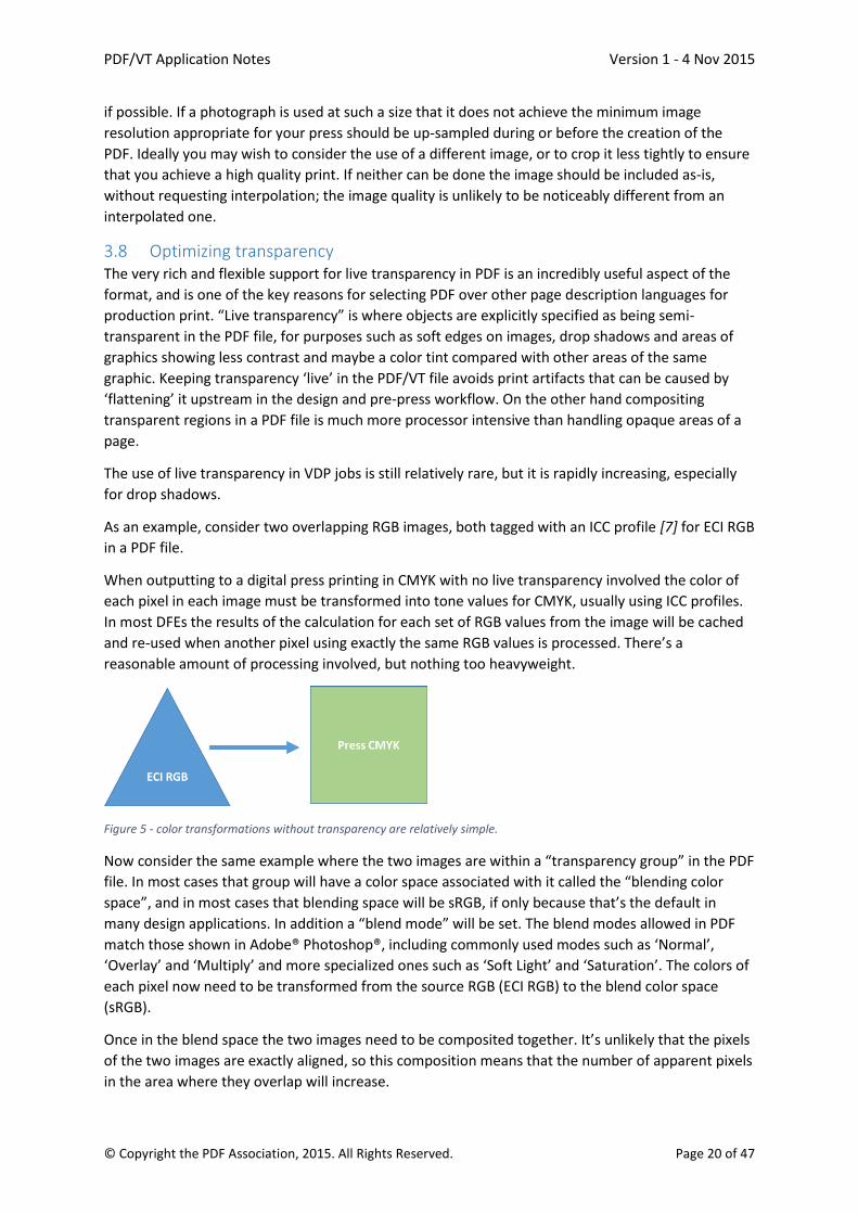
As an example, consider two overlapping RGB images, both tagged with an ICC profile [7] for ECI RGB
in a PDF file.
When outputting to a digital press printing in CMYK with no live transparency involved the color of
each pixel in each image must be transformed into tone values for CMYK, usually using ICC profiles.
In most DFEs the results of the calculation for each set of RGB values from the image will be cached
and re-used when another pixel using exactly the same RGB values is processed. There’s a
reasonable amount of processing involved, but nothing too heavyweight.
Figure 5 - color transformations without transparency are relatively simple.
Now consider the same example where the two images are within a “transparency group” in the PDF
file. In most cases that group will have a color space associated with it called the “blending color
space”, and in most cases that blending space will be sRGB, if only because that’s the default in
many design applications. In addition a “blend mode” will be set. The blend modes allowed in PDF
match those shown in Adobe® Photoshop®, including commonly used modes such as ‘Normal’,
‘Overlay’ and ‘Multiply’ and more specialized ones such as ‘Soft Light’ and ‘Saturation’. The colors of
each pixel now need to be transformed from the source RGB (ECI RGB) to the blend color space
(sRGB).
Once in the blend space the two images need to be composited together. It’s unlikely that the pixels
of the two images are exactly aligned, so this composition means that the number of apparent pixels
in the area where they overlap will increase.

PDF/VT Application Notes Version 1 - 4 Nov 2015
© Copyright the PDF Association, 2015. All Rights Reserved. Page 21 of 47
And finally the resulting colors in sRGB must be transformed to the output CMYK of the press.
Figure 6 - color transformations with transparency requires significantly more processing.
As you can see this process at least doubles the amount of effort required in color transformations,
even without taking into account the work to perform the transparency blending itself, which is
significant for some of the blend modes.
The impact of using transparency in a VDP job depends on whether it’s used in a ‘background’
graphic that’s used many times on many pages, or if it’s in variable data or a re-used object that
overlays variable data. If it’s in the background the VDP optimizations in many solutions will mean
that it only needs to be processed once, which resolves the transparency. The result of that
processing can be re-used multiple times so the extra work required in processing doesn’t add all
that much to the total job time. If it’s used in variable data or an object that overlays variable data
then the VDP optimizations in many DFEs will be circumvented and the whole of the page may need
to be processed as it stands without being able to re-use some or all previously processed elements.
The bottom line on transparency is that it’s very valuable, but if it’s not in the static background to
pages and it can be easily avoided without changing the final printed appearance then do so.
3.8.1 Don’t flatten transparency It may seem strange after the previous paragraph to say that transparency shouldn’t be flattened.
But flattening transparency upstream of the DFE can have two significant unwanted effects:
The transparency effect can sometimes be replaced with a huge number of very small
graphics in order to try to maintain exactly the same visual appearance. This not only bloats
the file size, but it can make the job even slower to RIP than working from the live
transparency would.
If the flattening is not performed with a detailed knowledge of the resolution and other
capabilities of the press the job will be output on it can introduce some unpleasant artifacts
in the output, such as jaggies or subtle color changes at the edges of flattened objects. Even
if you do know the full details for the press that will be used, a pre-flattened job would be
harder to transfer to another press at the last minute if you needed to.
3.8.2 Avoid invisible transparency effects Live transparency in PDF is probably most commonly used for drop shadows, but even that use
should be avoided if it doesn’t result in an effect that’s visible on the final printed piece. For
example, do not include drop shadows on images that are printed on a black background unless the
shadow will also fall on another element where it will be visible, such as another image on the page.

PDF/VT Application Notes Version 1 - 4 Nov 2015
© Copyright the PDF Association, 2015. All Rights Reserved. Page 22 of 47
Figure 7 - This image has a drop shadow on it, but it’s completely invisible against the black background.
Clearly there are exceptions to this where the drop shadow would still be visible on a print, even if
it’s not on a computer monitor, such as where the drop shadow paints in a rich black (e.g. black plus
40% cyan) and the background is printed with only black ink.
In the same way, if all you’re doing is adding drop shadows to text or images that fall entirely on a
white background, you don’t need to use transparency at all; a simple shading pattern will do
everything that you need. Of course, if any of the graphics with drop shadows overlap each other
you will need to use transparency, so that the shadows fall across the elements behind correctly.
If assets are being created in off-the-shelf design tools and then integrated with variable elements in
a composition tool this may be a difficult optimization to perform because many design tools offer a
simple switch to add a drop shadow, which includes turning on the transparency. On the other hand,
if everything is created and laid out within the composition tool it should be very achievable.
3.8.3 Use overprinting instead of transparency for black text and rules Printers using offset lithography and other conventional print technologies have used a little trick to
avoid registration errors between small black text and fine rules running over other graphics on a
page for many years: they set the black elements to overprint. This means that the text and rules
don’t knock out of the other graphics, which means that you’ll never see any white outlines as a
result of misregistration. More recently we’ve seen a few instances where people have used
transparency instead, using Overlay or Darken blend modes.
The potential for objectionable artifacts when using either approach is disappearingly small. The only
visible effect likely is that the black won’t be pure, but may have varying amounts of cyan, magenta
and yellow behind it. If these techniques are used only for small black text and rules then it’s hard to
see that variation at all, even with a lens.
Where overprinting and transparency do differ, however, is in the speed at which the DFE can
process them. A simple black overprint will often be very significantly faster, especially if the
background behind the black elements is complex or includes high-resolution images.
3.8.4 Use clips rather than masks Clipping an image, either to a smaller rectangle or to a more complex shape, can be done in several
ways, and these vary greatly in efficiency:
a) A vector clip-path is by far the most efficient and should be used wherever possible

PDF/VT Application Notes Version 1 - 4 Nov 2015
© Copyright the PDF Association, 2015. All Rights Reserved. Page 23 of 47
b) If the creation workflow is such that a vector clip-path cannot be applied, then use a masked
image (an image with a Mask entry)
c) By far the most expensive in processing power is a soft mask (SMask), which is the only one
of the three approaches that uses live transparency. These should only be used where a soft blend is
required, e.g. between an image and a special effect frame.
Some applications use a soft mask to clip an image only because a hard mask at the same resolution
as the main image would result in visible stepping around the edge. A vector clipping path will yield a
smoother edge than most hard masks and would be a suitable alternative to a soft mask in most
cases.
When a special effect frame is added to an image then it is usually printed on top of the image. It is
far more efficient to reveal the real image through the frame using one of the following techniques
than to add a soft mask to a frame supplied as an image:
a) Draw the frame using vector objects (far easier for some visual effects than for others). In
this case nothing extra is required to reveal the image through the center of the frame
b) Apply a clipping path to the frame object
c) Use a masked image (with a Mask entry) rather than an image with a SMask entry.
When using a frame with a complex irregular or non-rectangular shape that requires portions of the
real image to be hidden so that they are not visible outside the frame, a clipping path should be used
on the main image data as well. This often requires only a relatively rough outline as the clipping
path only needs to fall somewhere through the area covered by the frame and does not need to
track its edge exactly.
Figure 8 - clipping images instead of using transparency
3.8.5 Pre-composite images with soft masks Some VDP designs include the placement of one image with a soft mask over another background
image, perhaps to achieve a soft transition from one to another. If it is possible to composite the two
images with the soft mask into a single image before delivery to the DFE, the work required in the
DFE will be greatly reduced.
There is little benefit to be gained from compositing multiple images without masks simply because
they fall on the same page or because they overlap each other. The coalescing step of the VDP
optimization will normally achieve this stage quite efficiently.
PDF/VT Application Notes Version 1 - 4 Nov 2015
© Copyright the PDF Association, 2015. All Rights Reserved. Page 24 of 47
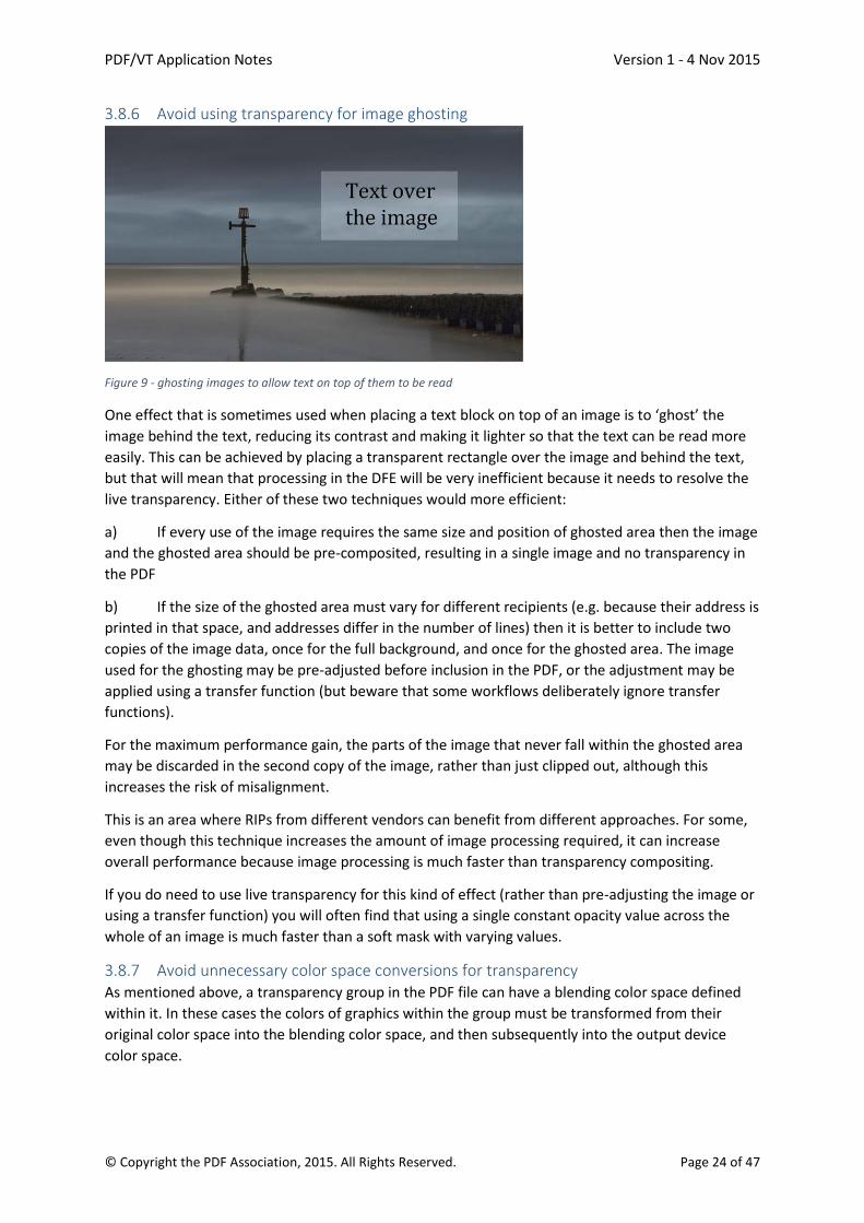
3.8.6 Avoid using transparency for image ghosting
Figure 9 - ghosting images to allow text on top of them to be read
One effect that is sometimes used when placing a text block on top of an image is to ‘ghost’ the
image behind the text, reducing its contrast and making it lighter so that the text can be read more
easily. This can be achieved by placing a transparent rectangle over the image and behind the text,
but that will mean that processing in the DFE will be very inefficient because it needs to resolve the
live transparency. Either of these two techniques would more efficient:
a) If every use of the image requires the same size and position of ghosted area then the image
and the ghosted area should be pre-composited, resulting in a single image and no transparency in
the PDF
b) If the size of the ghosted area must vary for different recipients (e.g. because their address is
printed in that space, and addresses differ in the number of lines) then it is better to include two
copies of the image data, once for the full background, and once for the ghosted area. The image
used for the ghosting may be pre-adjusted before inclusion in the PDF, or the adjustment may be
applied using a transfer function (but beware that some workflows deliberately ignore transfer
functions).
For the maximum performance gain, the parts of the image that never fall within the ghosted area
may be discarded in the second copy of the image, rather than just clipped out, although this
increases the risk of misalignment.
This is an area where RIPs from different vendors can benefit from different approaches. For some,
even though this technique increases the amount of image processing required, it can increase
overall performance because image processing is much faster than transparency compositing.
If you do need to use live transparency for this kind of effect (rather than pre-adjusting the image or
using a transfer function) you will often find that using a single constant opacity value across the
whole of an image is much faster than a soft mask with varying values.
3.8.7 Avoid unnecessary color space conversions for transparency As mentioned above, a transparency group in the PDF file can have a blending color space defined
within it. In these cases the colors of graphics within the group must be transformed from their
original color space into the blending color space, and then subsequently into the output device
color space.

PDF/VT Application Notes Version 1 - 4 Nov 2015
© Copyright the PDF Association, 2015. All Rights Reserved. Page 25 of 47
Many PDF files have transparency groups with a blending color space set to sRGB, simply because
that’s the default in a number of mainstream design tools, while the output device color space for
print is usually CMYK (or some variant upon that). The transparency doesn’t add any additional
transformation of the color information if the blend color space of the group matches either the
source color space of all graphics within the group or the device color space. The transforms may
occur at a slightly different place during processing, but the same amount of transformation is
required.
But if neither the source color space nor the device color space match the blending color space the
colors of all graphics must be transformed twice instead of once, increasing the overall processing
time.
Figure 10 - Choosing the blend color space carefully can greatly reduce color transformations required
If you can ensure that all graphics (especially images) within a group have the same source color
space as the blending space, or, even better, the blending space matches the output device color
space, then throughput in the DFE will be higher.
Switching the blending color space, especially between RGB and CMYK spaces, will often change the
final printed color. If you’re going to change the blend color space from something like sRGB to the
output CMYK for maximum DFE performance you need to make that decision early in your design
process and ensure that the resulting output is approved. If you need to stay with blending in RGB
you should ensure that the blend color space matches the source color space of all of your images
(or vice versa).
Occasionally transparency group operations may be chained together if a group is defined within
another group, although that is relatively rare. There can be good reasons for using this kind of
construct in commercial print, publication or newsprint work, such as when placing or imposing
multiple PDF/X files created for the same characterized print condition, but using different ICC
profiles in their output intents together. This might arise if you’re placing display ads, for instance. If
that kind of situation occurs in a VDP print job, however, you would be advised to review the
creation workflow and unify your asset design process further upstream to ensure consistent and
predictable output. In general nesting transparency groups should be avoided for VDP, and is
probably unnecessary anyway.
PDF/VT Application Notes Version 1 - 4 Nov 2015
© Copyright the PDF Association, 2015. All Rights Reserved. Page 26 of 47
3.9 Optimizing vector graphics Vector graphics are relatively quick to process compared to images, which is why this section is so
short.
3.9.1 Barcodes and QR Codes QR Codes and other barcodes can be represented on a PDF page in several different ways, including
as an image or using vector graphics. One dimensional barcodes can also be drawn with a barcode
font.
In terms of processing speed a barcode font is typically the most efficient, but can limit the
opportunities for compensating for edge growth to maximize readability. Using an image (or
imagemask) is generally slowest, so the best compromise tends to be to use vector graphics.
Composition vendors can assist here by turning on automatic stroke adjustment for bar codes (using
the SA graphics state parameter in the PDF) to minimize issues if the scaling is not absolutely correct.
3.9.2 Avoid unnecessary smooth shades Smooth shades were added into the PDF specification in the late nineties, and provide a way of
defining a variety of graduated tints or vignettes. They can be very useful, but tend to take a little
longer than a simple flat fill to process, especially if they happen to interact with any transparent
graphics on the page.
Don’t use a smooth shade where the final color doesn’t vary across the object; just use a flat tint
instead.
3.10 Optimizations in VDP workflow software The recommendations above are relevant for graphic designers and composition operators in at
least some workflows. But there are some optimizations that can only be addressed by the software
vendors involved, either in asset creation and management, or in the composition tools themselves.
These tend to be deeper into the technical aspects of exactly how a PDF file is constructed.
3.10.1 Embed each image in the PDF just once The data for images is embedded in the PDF file as an XObject. The description of the graphical
contents of each page then includes a pointer to the XObject to place that image on that page. If the
same image is used many times within a single PDF file then the image data can be embedded many
times, or it can be embedded just once and the pointer from the page descriptions can all point to
that same copy.
If multiple copies of the same image are embedded in the PDF that will evidently bloat the file size.
Less obviously it will reduce the efficiency of the VDP optimizations in some DFEs because the
images will be seen as different and therefore each copy may be processed separately, increasing
the work required unnecessarily and slowing the job down.
Whenever possible only one copy of each image should be embedded. If the same source image is
used at multiple different sizes on the pages those may either use the same embedded copy or a
separate copy at a suitable resolution may be used for each final size.
3.10.2 Don’t tile or stripe images A couple of decades ago it was common to write images into page description languages as a series
of rectangular tiles, or as strips. DFEs and RIPs at that time didn’t have access to much RAM, and the
intention was to ensure that the RIP didn’t need to hold very large amounts of image data at the

PDF/VT Application Notes Version 1 - 4 Nov 2015
© Copyright the PDF Association, 2015. All Rights Reserved. Page 27 of 47
same time. RAM costs are still a factor in DFE design but the amounts now used are many times
higher than they were back then, so this ‘workaround’ is no longer required.
On the other hand, there is a measurable cost for the RIP to set up and tear down a processing
pipeline for each image, so making the DFE handle a large number of small images instead of a single
large one makes it run slower.
One extreme example of inefficient practice can often be seen when an image has been placed on a
page in a design application and then a single color in the image has been marked as transparent by
the user. Some applications will generate a huge number of very small images, often in strips only
one pixel tall, in an output PDF. If they were to including the whole image as one, and using a stencil
mask or color key mask on that image it would increase processing speed in the DFE hugely.
And that slow-down is sometimes multiplied by encoding the image strips as in-line images instead
of Image XObjects. In-line images make it harder for the RIP to separate processing images from that
of the rest of the graphics within a page and therefore subvert some of the optimizations that might
otherwise be applied.
And finally, if an image is tiled or striped it’s vital that the coordinates of the edges of each sub-
image are encoded accurately and with high precision into the PDF file. It’s not uncommon to see
white lines on the printed output between sub-images where those coordinates have not been
written correctly.
3.10.3 Use a constant opacity rather than a soft mask with constant values There are two ways of specifying how transparent a graphic should be within a PDF file: you can set
a constant opacity value for fills and strokes (using the CA/ca keys), or you can attach a soft mask
(SMask in the PDF, or within a JPEG2000 image). Soft masks can be very useful if the transparency
should vary across the graphic, e.g. for softening the edges of an image. But we’ve also seen them
used quite a lot where the transparency is uniform across the whole graphic. The most inefficient
examples add a soft mask where all of the values are either 1.0 (indicating that the element is fully
opaque) or 0.0 (indicating that the element is fully transparent, and should not be visible at all).
If the element should be fully opaque the best way to represent that is to omit the SMask entry
completely, or to set it to /None.
If the element should be fully transparent (not visible) then don’t include it in the PDF file at all!
And if the element should have a constant transparency that is neither fully opaque, nor fully
transparent, just use the CA or ca keys to set that value and omit the SMask key or set its value to
/None.
3.10.4 Don’t subset fonts Some software subsets fonts when embedding them within a PDF file. It’s a technique that was
originally developed to reduce file sizes slightly and to make it marginally harder to copy fonts by
extracting them from PDF files. The incremental increase in file sizes to include a whole font in a VDP
file is now trivial compared to disk sizes and communications speeds, with the possible exception of
multi-byte fonts, for Japanese or Chinese for example. And most font vendors have adopted
different models for font sales that don’t rely on avoiding embedding them completely. So most of
the advantages of subsetting fonts have disappeared.
On the other hand there are distinct costs from subsetting fonts in a VDP job if that is performed per
page. Each subset of the font will be regarded by many RIPs as a different font. That means that the

PDF/VT Application Notes Version 1 - 4 Nov 2015
© Copyright the PDF Association, 2015. All Rights Reserved. Page 28 of 47
cache of rendered characters must be built from scratch for every different subset font, which slows
the job processing down slightly.
So we recommend that you don’t subset fonts in a VDP job or, if you do subset, you embed a single
subset that includes all of the glyphs used on all pages for all recipients.
If, however, you’re generating personalized instances of a PDF file for web or mobile device delivery
you may want to continue subsetting embedding fonts for each instance, especially if using multi-
byte fonts.
3.10.5 Use PDF/VT hints when possible If you’re making a PDF/VT file then each graphic in the file (expressed as a Form or Image XObject)
can have one or more ‘hints’ associated with it using the GTS_XID, GTS_Encapsulated, GTS_Scope
and GTS_Env keys. This allows the file to carry information about whether that graphic is used only
once or multiple times. It also allows it to say that the asset will look exactly the same every time it’s
used, or if it may be affected by other graphics around it. These hints can provide a short-cut for the
DFE’s optimizations, allowing it to make decisions more quickly.
If the information is available to set these hints correctly then you are recommended to do so, but
do not set the hints if you’re not confident that you will get them right.
3.11 Pre-printed paper stock One of the advantages of modern, high-volume digital presses that is often cited is the ability to
switch from the use of pre-printed stock (often referred to as pre-printed shells) to a “white paper
workflow” where the whole of every page is printed in a single pass through the press. This has
major advantages in reducing the costs of inventory management and of obsolete stock.
But in some cases, where a print provider prints only a limited range of jobs in very high volumes,
using paper stock pre-printed with a graphically rich background can reduce the load on the RIP and
maximize throughput. It removes the need to RIP those graphical elements as well as potentially
reducing the number of colorants for which a raster image needs to be created. For example using
pre-printed stock for post cards can dramatically reduce RIP time, as the images on the front of the
post card need not be ripped for each page.
PDF/VT Application Notes Version 1 - 4 Nov 2015
© Copyright the PDF Association, 2015. All Rights Reserved. Page 29 of 47
4 Ensuring Quality This section discusses features and methods for ensuring the output quality of PDF/VT files.
PDF/VT is based on PDF/X. In particular, each PDF/VT-1 file is also a PDF/X-4 file, and each PDF/VT-2
file set is also a PDF/X-5 or PDF/X-4p file set.
By this mechanism, PDF/VT inherits all properties ensuring high quality from PDF/X. The PDF/X
conformance levels have been designed to maximize output predictability and reproducibility and to
enable “blind exchange” between designers and print service providers.
4.1 Quality Features inherited by PDF/VT from PDF/X The following discussion is primarily about PDF/X-4 and PDF/VT-1, but is applicable as well to PDF/X-
5 and PDF/VT-2.
In most cases, the above properties of PDF/X-4 are realized as restrictions enforcing the safe use of
existing PDF features. They include, e.g.:
All font glyphs required embedded
Fully embedded images
Defined use of output intent
Restricted color spaces
Defined use of transparency
Restrictions on screening
Defined use of bounding boxes
Defined use of optional content
Restrictions on annotations
Restrictions on overprint mode
Also some features which may reduce predictability are forbidden, e.g.:
JavaScript
Actions
All of these features are present (or absent) likewise in PDF/VT-1. Thereby PDF/VT-1 inherits the
reliability provided by PDF/X-4.
As an example, consider device independent color in PDF/VT-1 as inherited from PDF/X-4.
A key aspect of PDF/X-4 device independence is the requirement that all color content is
colorimetrically defined to a printing condition through the use of an output intent ICC profile.
It is also required that conforming PDF/X-4 readers that render PDF/X-4 pages colorimetrically
interpret all color page content through the output intent profile's color transforms when rendering
content.
Thus proper use of color management when interpreting and rendering pages of a properly
prepared PDF/X-4 file should yield a rendered color appearance as intended by the designer. Of
course, the color gamut of the color printing device configured with the required paper substrate
should have a color gamut equal or larger than that of the target printing condition defined by the
output intent profile.
As a PDF/VT-1 file is also a PDF/X-4 file, the above properties are inherited for PDF/VT-1 files.

PDF/VT Application Notes Version 1 - 4 Nov 2015
© Copyright the PDF Association, 2015. All Rights Reserved. Page 30 of 47
4.2 Quality Recommendations inherited by PDF/VT from PDF/X A number of other features should be avoided because they jeopardize the output quality of PDF
files. The corresponding restrictions have been established as best practices (avoiding the feature)
and are offered as automatic preflight checks both for PDF/X and PDF/VT. They include:
Hairlines (lines below a certain line width (e.g. 0.1 pt.) or with line width 0)
Font size below a certain size
Use of Courier inside the trim / bleed box (possibly indicating a font not found problem)
Images below a certain resolution (depending on color mode of the image, device resolution
and screen resolution)
CMYK total colorant amount over a certain limit (e.g. 320%)
The above checks and best practices for PDF/X can be applied also for PDF/VT.
4.3 Quality for Variable Data Printing The following quality considerations arise because PDF/VT is intended for variable data printing:
Data integrity: The most important aspect is that each record from the data source is output exactly
once and exactly as provided by the data source.
The following conditions (which all apply to the variable data) should be checked (by the PDF/VT
writer) for each single record before or while creating the PDF/VT file:
Each text fits into the text box provided for it.
Clipping a non-fitting text or letting it exceed its text box would in general falsify the print
result and must be surely avoided.
Paragraph reflow keeps the layout rules of the VDP template.
Each text character is rendered by its corresponding glyph.
Certain characters might not be contained in the font of their variable text element. This
might be handled by a suitable font switch or rejected as not supported.
No text contains unprintable characters.
This is a more technically worded corollary of the previous condition.
Each text (or byte string) to be rendered as a barcode matches the conditions of that
barcode.
The text must be contained in the character set of the barcode, it must keep the minimum
and maximum data length of the barcode, and it may have to provide a correct check digit.
Specific barcodes may have further requirements.
Each referenced image is found and correctly embedded.
With the above conditions, the resulting PDF/VT file can be output correctly and consistently on a
variety of devices.
Printing each record exactly once, even in error situations, is a matter of the PDF/VT consumer
and/or the print service provider.
Long runs: Long runs are typical for VDP jobs. Long runs may raise issues such as ink laydown limits.
However, all such issues may also occur with static (PDF or PDF/X) jobs. They can be addressed in the
same way as for long static jobs.

PDF/VT Application Notes Version 1 - 4 Nov 2015
© Copyright the PDF Association, 2015. All Rights Reserved. Page 31 of 47
4.4 Device independent color: A key aspect of PDF/VT device independence is the requirement that all color content is
colorimetrically defined to a printing condition through the use of an output intent ICC profile in
accordance with PDF/X-4 requirements.
It is also required that conforming PDF/VT readers that render PDF/VT pages colorimetrically
interpret all color page content through the output intent profile’s color transforms when rendering
content.
Thus proper use of color management when interpreting and rendering pages of a properly
prepared PDF/VT file should yield the rendered color appearance as intended by the designer. Of
course, the color gamut of the color printing device configured with the required paper substrate
should have a color gamut equal or larger than that of the target printing condition defined by the
output intent profile.
4.4.1 Importance of color management in color variable document exchange In modern graphic arts practice, accurate communication of color content from the designer to the
print service provider (PSP) is essential and involves the use of a variety industry standards based
color management methods. Color management is important because PDF/VT files often contain a
large number of graphically rich and unique pages. By leveraging the managed color features of
PDF/X-4 and specifying the intended color appearance of each page in the file, there is a much
higher probability the final output created by the PSP will have the desired appearance. Keep in
mind, of course, that VDP jobs comprising diverse and often unique page content are difficult to
comprehensively proof.
Color management methods have become fundamental to modern color image capture, graphic
design, prepress, proofing and printing because they provide for concrete and efficient
communication of intended color appearance and significantly reduce the need for color proofing.
The application of industry standards and best practices surrounding modern color management and
the use of PDF/X files in color managed print applications mean that printed output is becoming
more and more consistent on a worldwide basis.
ICC based color management capability is available in the baseline feature sets of most image
capture and page design software solutions including systems ranging from digital cameras, flatbed
scanners, to desktop color printers, MFP office devices through to high end production digital
printers. In many areas, use of ICC profiles and color management is becoming somewhat
transparent to the end user.
Almost all production digital printing systems available today support calibration and process control
methods designed to manage the printer’s output color consistency, based on paper type, colorant
set and screening (printer setup). This, and the use of ICC profile creation tools that can generate ICC
destination (output) profiles, provide a consistent and predictable print color gamut for a given
printer setup, that can then be fully characterized using colorimetric measurements of standard and
proprietary color targets.
ICC destination profile files are typically stored in a “media library” to be used by the printer’s digital
front-end controller (DFE/RIP) in relation to each setup definition (i.e. named paper stock, screen
type, process colorant set).
These destination ICC profiles provide a colorimetric mapping from device CIE Lab values (ICC profile
connection space) to the calibrated device dependent (usually CMYK) process color space of a given
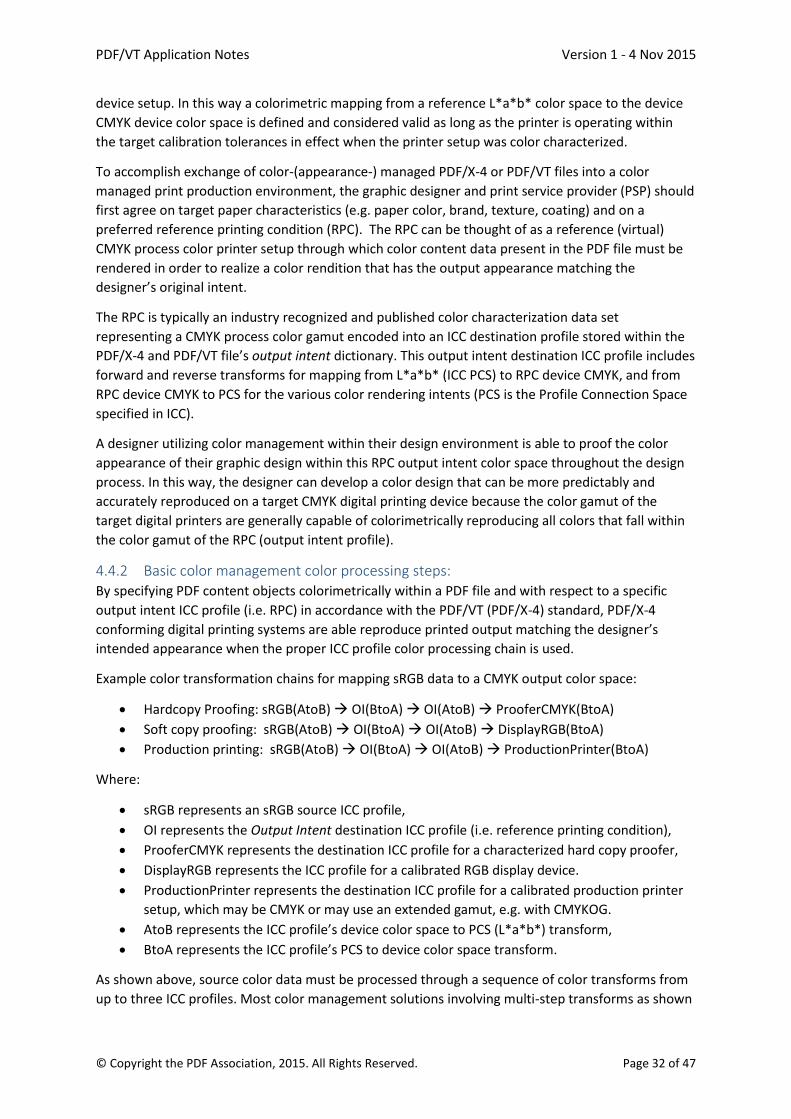
PDF/VT Application Notes Version 1 - 4 Nov 2015
© Copyright the PDF Association, 2015. All Rights Reserved. Page 32 of 47
device setup. In this way a colorimetric mapping from a reference L*a*b* color space to the device
CMYK device color space is defined and considered valid as long as the printer is operating within
the target calibration tolerances in effect when the printer setup was color characterized.
To accomplish exchange of color-(appearance-) managed PDF/X-4 or PDF/VT files into a color
managed print production environment, the graphic designer and print service provider (PSP) should
first agree on target paper characteristics (e.g. paper color, brand, texture, coating) and on a
preferred reference printing condition (RPC). The RPC can be thought of as a reference (virtual)
CMYK process color printer setup through which color content data present in the PDF file must be
rendered in order to realize a color rendition that has the output appearance matching the
designer’s original intent.
The RPC is typically an industry recognized and published color characterization data set
representing a CMYK process color gamut encoded into an ICC destination profile stored within the
PDF/X-4 and PDF/VT file’s output intent dictionary. This output intent destination ICC profile includes
forward and reverse transforms for mapping from L*a*b* (ICC PCS) to RPC device CMYK, and from
RPC device CMYK to PCS for the various color rendering intents (PCS is the Profile Connection Space
specified in ICC).
A designer utilizing color management within their design environment is able to proof the color
appearance of their graphic design within this RPC output intent color space throughout the design
process. In this way, the designer can develop a color design that can be more predictably and
accurately reproduced on a target CMYK digital printing device because the color gamut of the
target digital printers are generally capable of colorimetrically reproducing all colors that fall within
the color gamut of the RPC (output intent profile).
4.4.2 Basic color management color processing steps: By specifying PDF content objects colorimetrically within a PDF file and with respect to a specific
output intent ICC profile (i.e. RPC) in accordance with the PDF/VT (PDF/X-4) standard, PDF/X-4
conforming digital printing systems are able reproduce printed output matching the designer’s
intended appearance when the proper ICC profile color processing chain is used.
Example color transformation chains for mapping sRGB data to a CMYK output color space:
Hardcopy Proofing: sRGB(AtoB) OI(BtoA) OI(AtoB) ProoferCMYK(BtoA)
Soft copy proofing: sRGB(AtoB) OI(BtoA) OI(AtoB) DisplayRGB(BtoA)
Production printing: sRGB(AtoB) OI(BtoA) OI(AtoB) ProductionPrinter(BtoA)
Where:
sRGB represents an sRGB source ICC profile,
OI represents the Output Intent destination ICC profile (i.e. reference printing condition),
ProoferCMYK represents the destination ICC profile for a characterized hard copy proofer,
DisplayRGB represents the ICC profile for a calibrated RGB display device.
ProductionPrinter represents the destination ICC profile for a calibrated production printer
setup, which may be CMYK or may use an extended gamut, e.g. with CMYKOG.
AtoB represents the ICC profile’s device color space to PCS (L*a*b*) transform,
BtoA represents the ICC profile’s PCS to device color space transform.
As shown above, source color data must be processed through a sequence of color transforms from
up to three ICC profiles. Most color management solutions involving multi-step transforms as shown

PDF/VT Application Notes Version 1 - 4 Nov 2015
© Copyright the PDF Association, 2015. All Rights Reserved. Page 33 of 47
above can implement methods of optimizing color transform processing through the use of ICC
device link profiles where there is a specific requirement to maintain black as pure black, for
instance.
Since RGB color gamuts (e.g. sRGB), as often used for photographic images, are somewhat different
in shape and volume than the process color CMYK color gamut of a CMYK printer setup, the
perceptual color rendering intent of the OI(BtoA) transform is typically used as it is created using a
carefully crafted algorithm for mapping colors outside the color gamut of the CMYK output intent
(OI) color gamut to colors within it. Such mappings typically avoid techniques such as clipping the
out of gamut color to the surface of the OI color gamut and instead try to preserve some amount of
color modulation in order to preserve detail in the rendered appearance. Simply clipping the out of
gamut RGB color to the surface of the OI color gamut (e.g. an RPC), for example, may otherwise
introduce unwanted color artifacts as areas of color content would lose modelling and be
reproduced as fairly uniform flat color areas.
The out of gamut color mapping strategy is often a unique quality of the ICC profile creation tool
used to create the perceptual color intent transforms of the OI ICC profile and since the mapping
affects final appearance, it is often vital for the designer to visualize the design using exactly the
same output intent profile as will be used for print production.
Once the source color data has been mapped through the OI profile’s CMYK color space (the output
the OI(AtoB) transform used in the sequences above), the mapping to the CMYK printer device color
space requires little if any gamut compression (typically using relative colorimetric color rendering
intent) as the printer’s CMYK process color gamut is fairly similar in shape and often larger than that
of the chosen output intent profile.
The choice of RPC for the output intent profile is typically based on the surface characteristics and
color of the target paper substrate. For this reason, published industry standard RPC color
characterization data has been created and classified with respect to different substrate types (e.g.
newsprint, uncoated, matte and gloss coated) and is commonly used today; see the ICC
characterization registry [8].
The technical requirements and constraints on the use of PDF color spaces defined in the PDF/X-4
standard, and inherited by the PDF/VT standard, must be followed and implemented appropriately
by both PDF/VT authoring solutions, and PDF/VT rendering solutions in order to reliability
communicate the intended appearance of color pages into production.

PDF/VT Application Notes Version 1 - 4 Nov 2015
© Copyright the PDF Association, 2015. All Rights Reserved. Page 34 of 47
5 Preserving and conveying customer expectations
5.1 Business and Job information exchange Along with any PDF/VT files exchanged in a business transaction, it is necessary to include other information that relates to the business transaction and the identification of necessary auxiliary files and resources. This includes information necessary to verify that all files and resources needed to produce the job as intended by the sender are present in the production environment of the receiver. When using PDF/VT as the basis of the content data exchange, both parties agree that the intended appearance of the page content is explicit in the exchanged PDF data. In other words, both sender and receiver accept the appearance of pages as defined in the PDF/X standard as part of the contract. As part of the business and job info exchange it is necessary to convey a description of the physical aspects (e.g. paper type, binding style, cover parts, body parts, folds, inserts) of the print products to be manufactured including details of any variation in their physical characteristics. In the case where instructions exist in the definition of the job that affect variation among variable print products to be produced, it is necessary to exchange information regarding the metadata present in the PDF/VT file(s) that relate to those instructions. Whether these instructions are explicit in a supplied JDF job ticket, or in some other means of conveying this information, these instructions must always be defined in the context of the job definition. Part of the job description is to provide information that describes delivery (mailing) of the print products and the time deadline by which the print products must be delivered or sent for delivery.
5.2 Differences between device and production-independent and production-ready
PDF/VT. ISO 16612-2 (PDF/VT) is a flexible PDF based structured document format that can represent the
many unique documents and pages of a variable document print (VDP) job with varying degrees of
workflow and device independence.
At one end of the scale shown in the illustration below, a document composition system generates a
PDF/VT file without any assumptions as to how it might be later imposed, printed and finished. This
is referred to as a device and production-independent (or simply production independent) PDF/VT
file. In this case, the PDF/VT file might include document part (DPart) metadata stored within its
document part (DPart) structure that describes the physical properties (i.e. product intent) of the
print products per each recipient record with an expectation that it will be targeted to a production
workflow later on by a downstream prepress process.
At the other end of the scale, the PDF/VT file generated is pre-targeted for a specific production
workflow respective of a specific digital printing and finishing device configuration. This is referred to
as a production-ready PDF/VT file and is a representation that is more difficult or perhaps impossible
to later re-target to an alternate print production workflow.
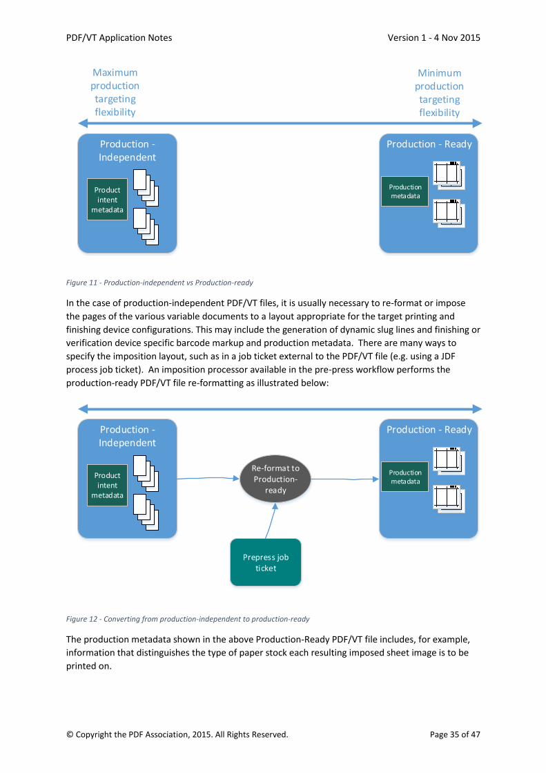
PDF/VT Application Notes Version 1 - 4 Nov 2015
© Copyright the PDF Association, 2015. All Rights Reserved. Page 35 of 47
Production - Ready
Maximum production targeting flexibility
Minimum production targeting flexibility
Production - Independent
Product intent
metadata
Production metadata
Figure 11 - Production-independent vs Production-ready
In the case of production-independent PDF/VT files, it is usually necessary to re-format or impose
the pages of the various variable documents to a layout appropriate for the target printing and
finishing device configurations. This may include the generation of dynamic slug lines and finishing or
verification device specific barcode markup and production metadata. There are many ways to
specify the imposition layout, such as in a job ticket external to the PDF/VT file (e.g. using a JDF
process job ticket). An imposition processor available in the pre-press workflow performs the
production-ready PDF/VT file re-formatting as illustrated below:
Production - ReadyProduction - Independent
Product intent
metadata
Production metadata
Re-format to Production-
ready
Prepress job ticket
Figure 12 - Converting from production-independent to production-ready
The production metadata shown in the above Production-Ready PDF/VT file includes, for example,
information that distinguishes the type of paper stock each resulting imposed sheet image is to be
printed on.

PDF/VT Application Notes Version 1 - 4 Nov 2015
© Copyright the PDF Association, 2015. All Rights Reserved. Page 36 of 47
The PDF/VT re-formatting or imposition processor is often implemented within the prepress
workflow capability of a modern integrated digital printing system’s digital front end processor (DFE)
as illustrated below:
Digital Printer Front End (DFE)
Production - ReadyProduction - Independent
Product intent
metadata
Production metadata
Re-format to Production-
ready
Digital printing job ticket
Figure 13 - Production targeting within the DFE
In this case the imposition layout requirements might be specified in the digital printing job ticket
(e.g. JDF).
How a PDF/VT file should be prepared by the composition engine typically depends on the business
requirements and lowest cost print production strategy which in turn depends on the complexity of
the VDP job and the capabilities of the variable document composition engine, prepress tools and
digital printing and finishing systems available in the production environment.
5.3 Variable document structuring and use of Document Part Metadata (DPM): PDF and PDF/X offer a standardized way to include metadata pertaining to the whole PDF document,
or to a page or sub-page unit (although the latter is rarely used)
In addition to those, PDF/VT offers Document Part Metadata (DPM) as a standardized way to include
metadata pertaining to recipient records, at a level that may be associated with groups of pages
rather than only at the page or document level.
These mechanisms can be used to add production metadata both for the whole document and
specifically for each recipient record.
The PDF/VT standard makes no assumptions as to the types of print products the various variable
documents specified within a file may represent. The only general convention defined in the
standard is that one level of the DPart hierarchy should be identified as the (recipient) record level
and all DPart nodes at that level are considered record level DPart nodes each representing one or
more documents or document parts.
Exactly what print product(s) or product parts a record level node and any of its child DPart nodes
are intended to represent depends on the semantics of the document part metadata (DPM)
associated with them. The syntax and semantics of DPM used to characterize DPart nodes is

PDF/VT Application Notes Version 1 - 4 Nov 2015
© Copyright the PDF Association, 2015. All Rights Reserved. Page 37 of 47
intentionally not defined by the ISO 16612-2 standard and was left to be defined by other
specifications, such as the CIP4 Common Metadata Specification [6].
For example, each record level node might represent a saddle stitched booklet and contain two child
DPart leaf nodes: one node representing the front and back surface content for a wrap-around cover
component and the other representing a reader order set of body pages as illustrated in the
following diagram:
Device & production-independent PDF/VT fileProduct Intent:BindingIntent = Saddle Stitch: Cover: Two sided wrap around cover, MediaIntent=Glossy
Body: Two sided, MediaIntent=Matte
DPM= BookletRecord 0
DPM= BookletRecord 1
DPM= BookletRecord 2
DPM= BookletRecord n
DPM = Cover
DPM = Body
DPM = Cover
DPM = Body
DPM = Cover
DPM = Body
Pages Tree:
DPartRootRecordLevel=1
Reader order PDF
Page objects
--------- DPart Node Hierarchy ----------
...DPM = Cover
DPM = Body
Output Intent ICC Profile
Figure 14 - Example DPM in a production-independent file (covers as spreads)
A record level DPart node can also represent the same set of saddle stitched booklets using a DPart
structure that includes separate FCover (front cover), Body and BCover (back cover) component
DPart nodes in that (reader) order. In this case the booklet cover is defined using two separate front
and back components each containing a front and back page rather than a single cover component
having two two-up imposed (front and back) surface content pages. The following diagram
illustrates three component booklets:

PDF/VT Application Notes Version 1 - 4 Nov 2015
© Copyright the PDF Association, 2015. All Rights Reserved. Page 38 of 47
Device & production-independent PDF/VT fileProduct Intent:BindingIntent = Saddle Stitch: FCover: Two sided cover, MediaIntent=Glossy Body: Two sided, MediaIntent=Matte
BCover: Two sided cover, MediaIntent=Glossy
DPM= BookletRecord 0
DPM= BookletRecord 1
DPM= BookletRecord 2
DPM= BookletRecord n
DPM = FCover
DPM = Body
DPM = FCover
DPM = Body
DPM = FCover
DPM = Body
Pages Tree:
DPartRootRecordLevel=1
Reader order PDF
Page objects
--------- DPart Node Hierarchy ----------
...
DPM = FCover
DPM = Body
DPM = BCover
DPM = BCover
DPM = BCover
DPM = BCover
Output Intent ICC Profile
Figure 15 - Example DPM in a production-independent file (covers as single pages)
As shown in the diagrams, DPart nodes are generally used to specify hierarchical component
structure as well as the relationship of reader order PDF pages to that structure.
The Document Part Metadata (DPM) present in each DPart node is used to specify the semantics of
each component respective the DPart structuring.
In the PDF/VT file diagrams, the metadata object in the PDF/VT file identified as Product Intent
formally defines the semantics of the print product and its components in terms of its physical
description.
The description indicates the saddle stitch booklet binding style (BindingIntent = SaddleStitch) and
the ordered list of the subcomponents to be bound together including two sided covers with a
substrate type (e.g. MediaIntent=Glossy) and a body component to be printed on matte substrate
(e.g. MediaIntent=Matte). The white dashed arrows in the diagram serve to illustrate the metadata
key value of the DPart node association with its detailed product intent definition.
The Product Intent metadata object used to describe the physical characteristics of the print
products is typically based on a semantic model and syntax defined by a public or private
specification such as the CIP4 Common Metadata Specification [6].
As seen in the example PDF/VT diagrams, the sets of pages at each leaf DPart node specifies the PDF
page ranges for cover and body components of each record’s booklet. According to the PDF/VT
standard, the order of each set of PDF pages is respective of the ordering represented in the PDF
Pages tree and is presumed to be in reader order.
It is important to note that the above diagrams represent PDF/VT files that are Production-
Independent as the file makes no assumption as to what printing device or production workflow will
be used to process the file and produce each unique booklet instance.
The representation of each print product in terms of how the print products are described (i.e. one
with single component covers and the other with two component covers) does of course impact the

PDF/VT Application Notes Version 1 - 4 Nov 2015
© Copyright the PDF Association, 2015. All Rights Reserved. Page 39 of 47
production planning decisions and ultimately the configuration of the workflow processes and tools
used to produce the print products.
5.4 PDF/VT file creation and production targeting As shown in the following process flow diagram, production independent files are generated from a
variable document composition process involving a database, set of merge rules, set of digital assets
and a graphical document design template. Of course there is a creative design process that is used
in the creation of the VDP design template and the merge rules that utilize the recipient database.
Many examples of such variable document design and composition tools are available on the market
today.
Another input to the PDF/VT file creation process shown in the diagram are Print Product
Requirements. These requirements represent the print product design and layout requirements that
describes the details of the print product known as the product intent.
Continuing with the earlier saddle stitch booklet example, this product intent information would
indicate that every recipient receives a custom saddle stitched booklet with cover and body pages
printed on two different paper substrates, etc… These requirements influence the template design
process and the product description is stored in the PDF/VT file as product intent metadata.
Print product Requirements
Merge Rules
Digital assets
Design & Compose Device and production
independent PDF/VT file
Recipient Database
Device and production
independent PDF/VT file
Create production plan
Job Ticket/Jacket/Bag(production
details)
Print, finish, package and deliver print
products
ExchangePDF/VT file
VDP design template
Production Capabilities
E.g. Job ticket based workflow where PDF/VT page imposition
occurs in digital printer DFE
Figure 16 - Device & Production Independent PDF/VT file creation, exchange and production-ready targeting without PDF/VT file conversion
Once the PDF/VT file is created and exchanged into the production environment, perhaps as a
resource of a print order, it must be examined by the planner or planning system and a print
production plan devised.
It is worth noting that the production Create production plan process shown in the diagram that
outputs the job ticket is typically automated in the case where the PDF/VT file DPart structure and
associated product intent aligns with routine conventions. For example, PDF/VT files generated by
an online web to print system back-end managed by the print provider.
In the above high level workflow scenario, the production plan created includes a job ticket (e.g.
JDF), or some other representation that describes how the PDF/VT based job is to be manufactured.
The plan specifies how the PDF/VT file’s documents and pages are to be targeted to a production
process. In the workflow shown, the target digital printing device’s DFE supports the two-up saddle
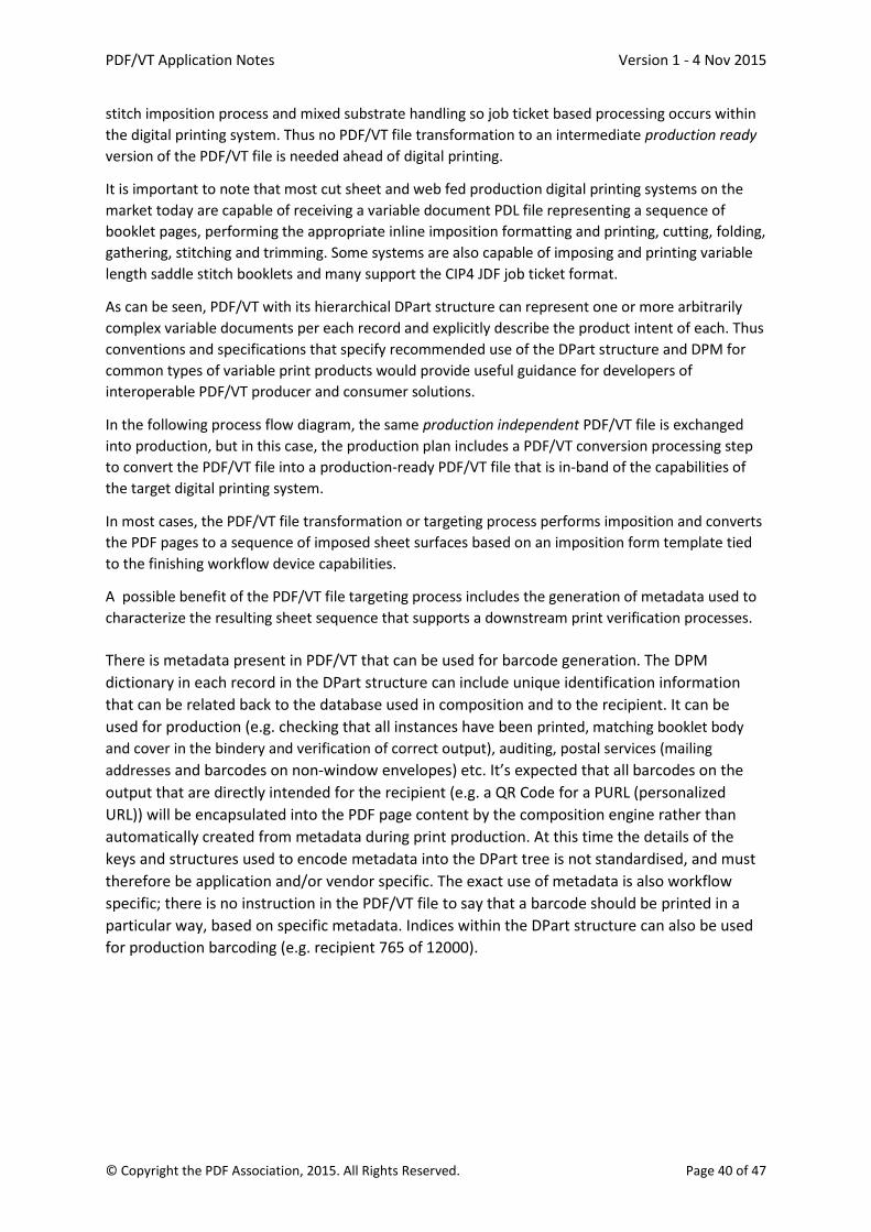
PDF/VT Application Notes Version 1 - 4 Nov 2015
© Copyright the PDF Association, 2015. All Rights Reserved. Page 40 of 47
stitch imposition process and mixed substrate handling so job ticket based processing occurs within
the digital printing system. Thus no PDF/VT file transformation to an intermediate production ready
version of the PDF/VT file is needed ahead of digital printing.
It is important to note that most cut sheet and web fed production digital printing systems on the
market today are capable of receiving a variable document PDL file representing a sequence of
booklet pages, performing the appropriate inline imposition formatting and printing, cutting, folding,
gathering, stitching and trimming. Some systems are also capable of imposing and printing variable
length saddle stitch booklets and many support the CIP4 JDF job ticket format.
As can be seen, PDF/VT with its hierarchical DPart structure can represent one or more arbitrarily
complex variable documents per each record and explicitly describe the product intent of each. Thus
conventions and specifications that specify recommended use of the DPart structure and DPM for
common types of variable print products would provide useful guidance for developers of
interoperable PDF/VT producer and consumer solutions.
In the following process flow diagram, the same production independent PDF/VT file is exchanged
into production, but in this case, the production plan includes a PDF/VT conversion processing step
to convert the PDF/VT file into a production-ready PDF/VT file that is in-band of the capabilities of
the target digital printing system.
In most cases, the PDF/VT file transformation or targeting process performs imposition and converts
the PDF pages to a sequence of imposed sheet surfaces based on an imposition form template tied
to the finishing workflow device capabilities.
A possible benefit of the PDF/VT file targeting process includes the generation of metadata used to
characterize the resulting sheet sequence that supports a downstream print verification processes.
There is metadata present in PDF/VT that can be used for barcode generation. The DPM
dictionary in each record in the DPart structure can include unique identification information
that can be related back to the database used in composition and to the recipient. It can be
used for production (e.g. checking that all instances have been printed, matching booklet body
and cover in the bindery and verification of correct output), auditing, postal services (mailing
addresses and barcodes on non-window envelopes) etc. It’s expected that all barcodes on the
output that are directly intended for the recipient (e.g. a QR Code for a PURL (personalized
URL)) will be encapsulated into the PDF page content by the composition engine rather than
automatically created from metadata during print production. At this time the details of the
keys and structures used to encode metadata into the DPart tree is not standardised, and must
therefore be application and/or vendor specific. The exact use of metadata is also workflow
specific; there is no instruction in the PDF/VT file to say that a barcode should be printed in a
particular way, based on specific metadata. Indices within the DPart structure can also be used
for production barcoding (e.g. recipient 765 of 12000).
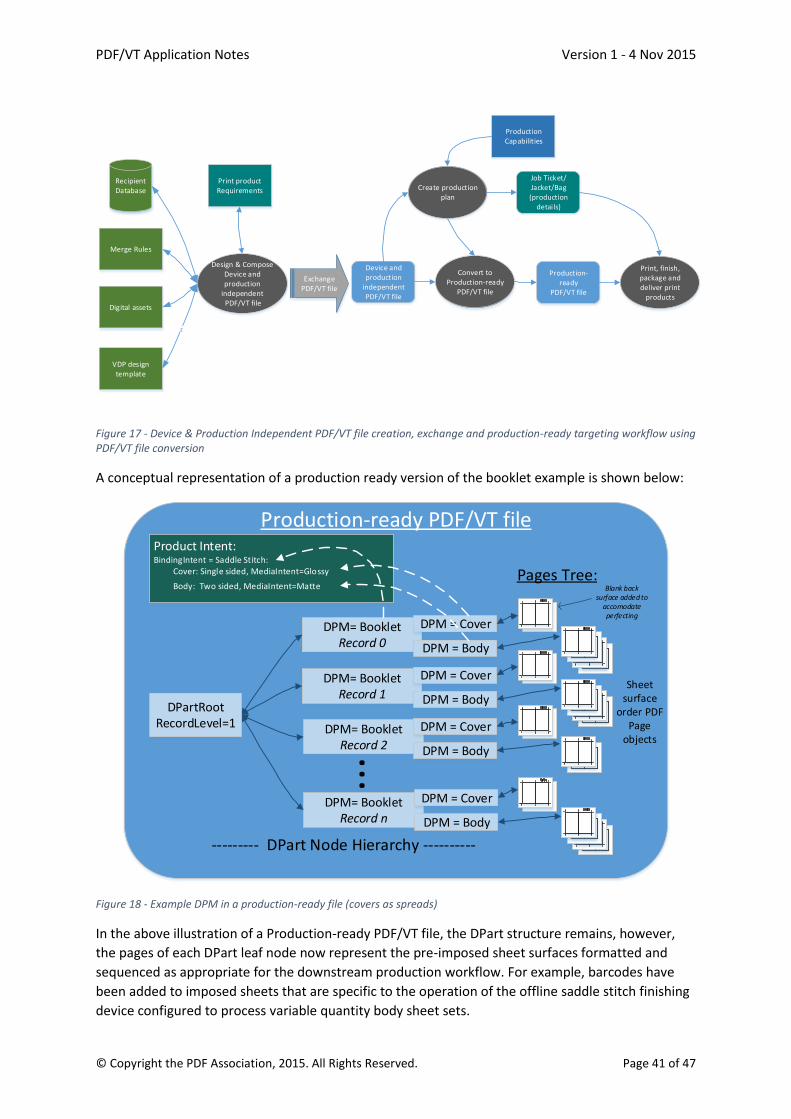
PDF/VT Application Notes Version 1 - 4 Nov 2015
© Copyright the PDF Association, 2015. All Rights Reserved. Page 41 of 47
Print product Requirements
Merge Rules
Digital assets
Design & Compose Device and production
independent PDF/VT file
Recipient Database
Device and production
independent PDF/VT file
Create production plan
Job Ticket/Jacket/Bag(production
details)
Print, finish, package and deliver print
products
ExchangePDF/VT file
VDP design template
Convert to Production-ready
PDF/VT file
Production- ready
PDF/VT file
Production Capabilities
Figure 17 - Device & Production Independent PDF/VT file creation, exchange and production-ready targeting workflow using PDF/VT file conversion
A conceptual representation of a production ready version of the booklet example is shown below:
Production-ready PDF/VT fileProduct Intent:BindingIntent = Saddle Stitch: Cover: Single sided, MediaIntent=Glossy
Body: Two sided, MediaIntent=Matte
DPM= BookletRecord 0
DPM= BookletRecord 1
DPM= BookletRecord 2
DPM= BookletRecord n
DPM = Cover
DPM = Body
DPM = Cover
DPM = Body
DPM = Cover
DPM = Body
Pages Tree:
DPartRootRecordLevel=1
Sheet surface
order PDF Page
objects
Blank back surface added to
accomodate perfecting
--------- DPart Node Hierarchy ----------
...
DPM = Cover
DPM = Body
Figure 18 - Example DPM in a production-ready file (covers as spreads)
In the above illustration of a Production-ready PDF/VT file, the DPart structure remains, however,
the pages of each DPart leaf node now represent the pre-imposed sheet surfaces formatted and
sequenced as appropriate for the downstream production workflow. For example, barcodes have
been added to imposed sheets that are specific to the operation of the offline saddle stitch finishing
device configured to process variable quantity body sheet sets.

PDF/VT Application Notes Version 1 - 4 Nov 2015
© Copyright the PDF Association, 2015. All Rights Reserved. Page 42 of 47
Although the pages of the PDF file have been converted to imposed sheet surfaces to be printed as a
sequence of front and back sheet surfaces for two sided printing, the DPM structuring for the cover
and body sheets remains as it is still necessary to inform the sheet fed digital printer where to pull
paper from (Glossy cover or matte Body) when printing sheets of each component type.
It is worth noting that the above representation of pre-imposed saddle stitch booklets is
representative of the output of the PDF/VT transform (targeting) process when converting either of
the two PDF/VT saddle stitch examples of two component booklets and three component booklets.
In the scenario where a print service provider provides both variable document creation and print
manufacturing services it is sometimes more efficient to generate production-ready PDF/VT files
directly. This is often the case when variable print product type offerings are standardized and pre
associated with specific VDP workflow configurations (e.g. single or multi substrate saddle stitch
booklets, tri-fold brochures, postcards, etc…). In this case, generating production independent
PDF/VT files has little value given the low expectation that a PDF/VT based job will need to be re-
targeted.
Print product Requirements
Merge Rules
Digital assets
Design & Compose Production-ready
PDF/VT file
Recipient Database
Production- ready
PDF/VT file
Create production plan
Job Ticket/Jacket/Bag(production
details)
Print, finish, package and deliver print
products
VDP design template
Production Capabilities
Figure 19 - Production-ready PDF/VT file creation and early production workflow and device targeting
In the above workflow diagram the PDF/VT file generated by the composition process is Production-
ready where the Design & Composition process is informed by both the print product requirements
and production details. In this scenario, there is little or no need to include product intent oriented
metadata within the PDF/VT file, however, DPM is still necessary in DPart nodes to distinguish
document parts if they have different processing requirements including substrate selection.

PDF/VT Application Notes Version 1 - 4 Nov 2015
© Copyright the PDF Association, 2015. All Rights Reserved. Page 43 of 47
6 Common document types This section lists some of the most common document types that might be printed using PDF/VT,
with some brief descriptions.
The lists below cover the following items typically associated with the document type:
• Content
• Media
• Finishing
6.1 Postcards Front: glossy image (typically 1 of a small number of images, selected on the basis of
metadata about the recipient)
Back: offer/marketing message + scale to fit address + postal marks
Heavy stock, single page, no envelope, no inserter marks, postal marks
Edge-to-edge printing or cutting required
6.2 Business cards
6.2.1 Single-sided
Text with name, email, telephone number
Company logo
Heavy stock, single page, no envelope, no inserter marks
6.2.2 Dual-sided
Front: Text with name, email, telephone number
Back: Company logo
Heavy stock, single page, no envelope, no inserter marks
6.3 Enveloped documents
6.3.1 Single page letters
address + logo
marketing text with an offer for a service/product
Signature (may be dependent on recipient metadata, e.g. sales region)
Single preprinted stock, single page, windowed envelope with folded pages, no inserter marks, postal marks
6.3.2 Multi page letters
Address + logo on first page
Marketing text with an offer for service/product
Signature (may be dependent on recipient metadata, e.g. sales region)
Preprinted stock for first page, blank stock for remaining pages, windowed envelope with folded pages, inserter marks, postal marks
6.4 Invoices Address + logo on first page
Table with detail lines (typically with some simple lines/filled areas)
Optional: pre-filled money order/check on last page
Optional: white space management: image/text to upsell products (usually chosen from a small set of static offers based on recipient metadata)

PDF/VT Application Notes Version 1 - 4 Nov 2015
© Copyright the PDF Association, 2015. All Rights Reserved. Page 44 of 47
Preprinted stock for first page, blank stock for middle pages, perforated stock for last page (detachable money order), windowed envelope with folded pages, inserter marks, postal marks
6.5 Statements Address + logo on first page
Typically contains business graphics (stock performance, gas/water/electricity usage, portfolio distribution)
One or more tables with detail information (typically with some simple lines/filled areas)
Options: o Cover with address imprinted o Separate cover letter that contains the address
Heavier pre-printed stock for first page/wrap around cover, windowed large envelope, postal marks
Finishing options: o saddle stitched booklet o folded brochure o corner stapled o wrap-around cover with loose pages inside

PDF/VT Application Notes Version 1 - 4 Nov 2015
© Copyright the PDF Association, 2015. All Rights Reserved. Page 45 of 47
7 Common production workflows and techniques
7.1 Cut & Stack The cut & stack workflow optimizes the production of smaller documents such as postcards and
business cards by placing multiple items onto a single sheet. After printing the produced sheets are
then cut and stacked in a predetermined manner to produce the original set of documents in the
intended order.
7.2 Pre-printed paper stock The use of pre-printed paper stock allows the production of limited color documents to be optimized
by over printing preprinted shells in black & white mode. Typically the preprinted shells are mass-
produced using offset printing to reduce the cost per page. A printer with multiple input trays can
support multiple backgrounds, which can be picked on demand (depending on the document being
produced). For example an otherwise black & white invoice will often use a logo on the first page
and the image of a check on the last page, which can be produced by using 3 types of pre-printed
paper stock (logo, blank and check) on a printer with at least 3 input trays.
7.3 Automatic enveloping In variable data printing the recipient of each document is typically a different person so that each
document will need to be sent to the recipient in a correctly addressed envelope. With larger
volumes of documents an inserter machine is typically used to save on labor costs and to reduce
errors in the inserting process.
For variable length documents the inserter machine will typically use a barcode reader to determine
which pages belong together in a single envelope. This requires that the printed document include a
barcode to identify which pages belong together, ensuring that only the intended recipient will
receive the pages intended for him. Part of the production process is to add those barcodes for the
inserter machine that will be used (a given production plant may have multiple machines from
different vendors).
For fixed length documents the inserter machine can be setup to always insert the same number of
sheets into an envelope. This is typically used in promotional print jobs where the added security of
the barcode is not required to ensure that documents are not sent to the wrong person.
For inserting devices that are in line with the printer, no additional marks need to be printed as the
pages are tracked electronically through the paper paths.
7.4 Windowed envelopes In order to simplify the production process, the variable data documents can be designed such that
the first page of each document contains the address of the recipient. The location of the address on
the page is chosen such that after folding and inserting the pages into the envelope the address will
show through a window in the envelope.
7.5 Non-windowed envelopes Sometimes a non-windowed envelope must be used to ensure that content can only be seen by the
intended recipient. This is typically the case for sensitive documents such as credit card pin letters,
bank statements, etc.
One production method relies on the first page of each document to be printed on a pre-made
envelope, containing the address. Typically the pre-made envelope is selected from a special input
tray in the printer.
PDF/VT Application Notes Version 1 - 4 Nov 2015
© Copyright the PDF Association, 2015. All Rights Reserved. Page 46 of 47
The other production method relies on the inserter machine imprinting the address “on-the-fly” just
before inserting the pages of the document into the envelope. The address is typically identified
from the barcode on the pages that is scanned by the inserter machine. Either the address is
completely included in the (2D) barcode or the barcode contains a unique document identifier,
which is used by the inserter machine to lookup the address in a database. In the case of PDF/VT
that database may be created from metadata present in the PDF/VT file for each document.
7.6 Self-mailers In order to simplify the production process, the variable data documents can also be designed such
that the first page of a document is intended to be folded and glued/sealed together to form an
envelope for the remaining pages of the document which are folded and inserted into the envelope
that is created on the fly.

PDF/VT Application Notes Version 1 - 4 Nov 2015
© Copyright the PDF Association, 2015. All Rights Reserved. Page 47 of 47
8 Bibliography
[1] PDF
ISO 32000-1:2008, Document Management – Portable Document Format – Part 1: PDF 1.7
[2] PDF/X-1a
ISO 15930-4:2003, Graphic technology — Prepress digital data exchange using PDF — Part 4:
Complete exchange of CMYK and spot colour printing data using PDF 1.4 (PDF/X-1a)
[3] PDF/X-3
ISO 15930-6:2003, Graphic technology — Prepress digital data exchange using PDF — Part 6:
Complete exchange of printing data suitable for colour-managed workflows using PDF 1.4
(PDF/X-3)
[4] PDF/X-4 and PDF/X-4p
ISO 15930-7:2010, Graphic technology — Prepress digital data exchange using PDF — Part 7:
Complete exchange of printing data (PDF/X-4) and partial exchange of printing data with
external profile reference (PDF/ X-4p) using PDF 1.6
[5] PDF/X-5
ISO 15930-8:2010/Cor 1:2011, Graphic technology — Prepress digital data exchange using PDF
— Part 8: Partial exchange of printing data using PDF 1.6 (PDF/X-5)
[6] CIP4 Common Metadata specification
Common Metadata for Document Production Workflows ICS.
Available from www.cip4.org.
[7] ICC
ICC specifications are available from www.color.org.
Version 2
Specification ICC.1:2001-04, File Format for Color Profiles
Version 4
Specification ICC.1:2010-12 (Profile version 4.3.0.0) Image technology colour management -
Architecture, profile format, and data structure
ISO (technically identical to ICC version 4)
ISO 15076-1:2010, Image technology colour management – Architecture, profile format and
data structure – Part 1: Based on ICC.1:2010
[8] ICC color characterization registry
Available at www.color.org.