pe6108av / pe6208av / pe8208av 8-outlets eco pdu user … · eco pdu pe series user manual iii user...
TRANSCRIPT

PE6108AV / PE6208AV / PE8208AV8-Outlets eco PDU
User Manual
www.aten.com

PE6108AV / PE6208AV / PE8208AV User Manual
ii
EMC Information
FEDERAL COMMUNICATIONS COMMISSION INTERFERENCE STATEMENT: This equipment has been tested and found to comply with the limits for a Class A digital device, pursuant to Part 15 of the FCC Rules. These limits are designed to provide reasonable protection against harmful interference when the equipment is operated in a commercial environment. This equipment generates, uses, and can radiate radio frequency energy and, if not installed and used in accordance with the instruction manual, may cause harmful interference to radio communications. Operation of this equipment in a residential area is likely to cause harmful interference in which case the user will be required to correct the interference at his own expense.
The device complies with Part 15 of the FCC Rules. Operation is subject to the following two conditions: (1) this device may not cause harmful interference, and (2) this device must accept any interference received, including interference that may cause undesired operation.
FCC Caution: Any changes or modifications not expressly approved by the party responsible for compliance could void the user's authority to operate this equipment.
Warning: Operation of this equipment in a residential environment could cause radio interference.
KCC Statement이 기기는 업무용 (A 급 ) 전자파 적합기기로서 판매자 또는 사용자는 이점을 주의하시기 바라며 , 가정외의 지역에서 사용하는 것을 목적으로합니다 .
RoHS
This product is RoHS compliant.
eco PDU PE Series User Manual
iii
User Information
Online RegistrationBe sure to register your product at our online support center:
Telephone SupportFor telephone support, call this number:
User NoticeAll information, documentation, and specifications contained in this manual are subject to change without prior notification by the manufacturer. The manufacturer makes no representations or warranties, either expressed or implied, with respect to the contents hereof and specifically disclaims any warranties as to merchantability or fitness for any particular purpose. Any of the manufacturer's software described in this manual is sold or licensed as is. Should the programs prove defective following their purchase, the buyer (and not the manufacturer, its distributor, or its dealer), assumes the entire cost of all necessary servicing, repair and any incidental or consequential damages resulting from any defect in the software.
The manufacturer of this system is not responsible for any radio and/or TV interference caused by unauthorized modifications to this device. It is the responsibility of the user to correct such interference.
The manufacturer is not responsible for any damage incurred in the operation of this system if the correct operational voltage setting was not selected prior to operation. PLEASE VERIFY THAT THE VOLTAGE SETTING IS CORRECT BEFORE USE.
If any bodily injury or property damage with respect to operation of the product results from users not having installed the product in accordance with the instructions provided in the product’s user manual, or the product is used in an environment with a current load over the designed specifications of the product, ATEN is not liable for any loss or damage.
International http://eservice.aten.com
International 886-2-8692-6959
China 86-400-810-0-810
Japan 81-3-5615-5811
Korea 82-2-467-6789
North America 1-888-999-ATEN ext 49881-949-428-1111

PE6108AV / PE6208AV / PE8208AV User Manual
iv
PE Device Safety Notice
Consignes de sècuritè relatives à l’unitè PE
Installez sur le circuit du bâtiment des disjoncteurs permettant d’assurer la protection maximale autorisée, en respectant le courant nominal spécifié sur la plaque signalétique. Veuillez respecter l’ensemble des réglementations nationales en vigueur et des codes de sécurité ainsi que les déviations recommandèes pour les disjoncteurs.
Ne connectez l’unité PE qu’à une prise de courant avec borne de terre ou à un système mis à la terre!
Assurez-vous que le courant d’entrée total des systèmes connectés ne dépasse pas le courant nominal spécifié sur la plaque signalétique de l’unité PE.
Il existe un risque d’explosion si la batterie est remplacée par une batterie de type incorrect. Jetez les batteries usagées en respectant les instructions adequates.
Set the maximum permissible breaker protection in the building circuitry to the current rating specified on the rating plate. Observe all national regulations and safety codes as well as deviations for breakers.Only connect the PE Device to a grounded power outlet or a grounded system! Make sure that the total current input of the connected systems does not exceed the current rating specified on the rating plate of the PE Device.There is a risk of explosion if the battery is replaced with an incorrect type. Dispose of used batteries according to the relevant instructions.

eco PDU PE Series User Manual
v
Package Contents
The eco PDU PE6108AV/6208AV Series package consists of:1 PE6108AVA/PE6208AVA/PE6208AVB/PE6208AVG/PE6208AVX Power Distribution Unit1 Power Cord (not available for PE6208AVX)1 RJ-45 Cable10 Cable Ties (only for J plug)1 Footpad Set1 Mounting Kit1 User Instructions*
The eco PDU PE8208AV Series package consists of:1 PE8208AV Power Distribution Unit1 Power Cord1 RJ-45 Cable4 Cable Ties1 Footpad Set1 Mounting Kit1 User Instructions*
Check to make sure that all of the components are present and in good order. If anything is missing, or was damaged in shipping, contact your dealer.
Read this manual thoroughly and follow the installation and operation procedures carefully to prevent any damage to the switch or to any other devices on the eco PDU installation.
* Features may have been added to the eco PDU since this manual was published. Please visit our website to download the most up-to-date version.
Copyright © 201 ATEN® International Co., Ltd.
Date Published: 2018-09-11
NRGence and the NRGence logo are registered trademarks of ATEN International Co., Ltd. All rights reserved. All other brand names and trademarks are the registered property of their respective owners.

PE6108AV / PE6208AV / PE8208AV User Manual
vi
Contents
EMC Information. . . . . . . . . . . . . . . . . . . . . . . . . . . . . . . . . . . . . . . . . . . . . iiRoHS . . . . . . . . . . . . . . . . . . . . . . . . . . . . . . . . . . . . . . . . . . . . . . . . . . . . . iiUser Information . . . . . . . . . . . . . . . . . . . . . . . . . . . . . . . . . . . . . . . . . . . . . iii
Online Registration . . . . . . . . . . . . . . . . . . . . . . . . . . . . . . . . . . . . . . . . iiiTelephone Support . . . . . . . . . . . . . . . . . . . . . . . . . . . . . . . . . . . . . . . . iiiUser Notice . . . . . . . . . . . . . . . . . . . . . . . . . . . . . . . . . . . . . . . . . . . . . . iiiPE Device Safety Notice . . . . . . . . . . . . . . . . . . . . . . . . . . . . . . . . . . . .ivConsignes de sècuritè relatives à l’unitè PE . . . . . . . . . . . . . . . . . . . . .iv
Package Contents . . . . . . . . . . . . . . . . . . . . . . . . . . . . . . . . . . . . . . . . . . . vContents . . . . . . . . . . . . . . . . . . . . . . . . . . . . . . . . . . . . . . . . . . . . . . . . . . .viAbout This Manual . . . . . . . . . . . . . . . . . . . . . . . . . . . . . . . . . . . . . . . . . . .ix
Conventions . . . . . . . . . . . . . . . . . . . . . . . . . . . . . . . . . . . . . . . . . . . . . xProduct Information . . . . . . . . . . . . . . . . . . . . . . . . . . . . . . . . . . . . . . . . . . x
Chapter 1.IntroductionOverview. . . . . . . . . . . . . . . . . . . . . . . . . . . . . . . . . . . . . . . . . . . . . . . . . . . 1Features . . . . . . . . . . . . . . . . . . . . . . . . . . . . . . . . . . . . . . . . . . . . . . . . . . . 3
Connections . . . . . . . . . . . . . . . . . . . . . . . . . . . . . . . . . . . . . . . . . . . . . 3Metering . . . . . . . . . . . . . . . . . . . . . . . . . . . . . . . . . . . . . . . . . . . . . . . . 3Outlet Switch Control . . . . . . . . . . . . . . . . . . . . . . . . . . . . . . . . . . . . . . 3
Requirements . . . . . . . . . . . . . . . . . . . . . . . . . . . . . . . . . . . . . . . . . . . . . . . 4Optional Accessories . . . . . . . . . . . . . . . . . . . . . . . . . . . . . . . . . . . . . . . . . 5
Sensors . . . . . . . . . . . . . . . . . . . . . . . . . . . . . . . . . . . . . . . . . . . . . . . . . 5Cable Holders . . . . . . . . . . . . . . . . . . . . . . . . . . . . . . . . . . . . . . . . . . . . 5
Components . . . . . . . . . . . . . . . . . . . . . . . . . . . . . . . . . . . . . . . . . . . . . . . . 6PE6108AV / PE6208AV / PE8208AV Front View . . . . . . . . . . . . . . . . . 6PE6108AV / PE6208AV / PE8208AV Rear View (exclude PE6208AVX) . . . . . . . . . . . . . . . . . . . . . . . . . . . . . . . . . . . . . . . . . . . . . . . . . . . . . . 8PE6208AVX Rear View. . . . . . . . . . . . . . . . . . . . . . . . . . . . . . . . . . . . . 9
Chapter 2.Hardware SetupBefore You Begin . . . . . . . . . . . . . . . . . . . . . . . . . . . . . . . . . . . . . . . . . . . 11Stacking and Rack Mounting . . . . . . . . . . . . . . . . . . . . . . . . . . . . . . . . . . 11
Stacking . . . . . . . . . . . . . . . . . . . . . . . . . . . . . . . . . . . . . . . . . . . . . . . 11Rack Mounting . . . . . . . . . . . . . . . . . . . . . . . . . . . . . . . . . . . . . . . . . . 13
Power Cord Installation (PE6208AVX) . . . . . . . . . . . . . . . . . . . . . . . . . . . 15Before Installation . . . . . . . . . . . . . . . . . . . . . . . . . . . . . . . . . . . . . . . . 15Cord Selection. . . . . . . . . . . . . . . . . . . . . . . . . . . . . . . . . . . . . . . . . . . 15Plug Selection . . . . . . . . . . . . . . . . . . . . . . . . . . . . . . . . . . . . . . . . . . . 15Installation . . . . . . . . . . . . . . . . . . . . . . . . . . . . . . . . . . . . . . . . . . . . . . 16
Installation. . . . . . . . . . . . . . . . . . . . . . . . . . . . . . . . . . . . . . . . . . . . . . . . . 19Securing the Cables . . . . . . . . . . . . . . . . . . . . . . . . . . . . . . . . . . . . . . 21Securing the Sensors . . . . . . . . . . . . . . . . . . . . . . . . . . . . . . . . . . . . . 22
Chapter 3.Basic Operation and

eco PDU PE Series User Manual
vii
First Time SetupOperation Methods . . . . . . . . . . . . . . . . . . . . . . . . . . . . . . . . . . . . . . . . . . 23
Browser . . . . . . . . . . . . . . . . . . . . . . . . . . . . . . . . . . . . . . . . . . . . . . . . 23eco Sensors . . . . . . . . . . . . . . . . . . . . . . . . . . . . . . . . . . . . . . . . . . . . 23SNMP . . . . . . . . . . . . . . . . . . . . . . . . . . . . . . . . . . . . . . . . . . . . . . . . . 23
First Time Setup . . . . . . . . . . . . . . . . . . . . . . . . . . . . . . . . . . . . . . . . . . . . 24Network Configuration. . . . . . . . . . . . . . . . . . . . . . . . . . . . . . . . . . . . . 25Changing the Administrator Login . . . . . . . . . . . . . . . . . . . . . . . . . . . . 26
Moving On. . . . . . . . . . . . . . . . . . . . . . . . . . . . . . . . . . . . . . . . . . . . . . . . . 26
Chapter 4.Browser OperationLogging In . . . . . . . . . . . . . . . . . . . . . . . . . . . . . . . . . . . . . . . . . . . . . . . . . 27The eco PDU Main Page . . . . . . . . . . . . . . . . . . . . . . . . . . . . . . . . . . . . . 28
Page Components. . . . . . . . . . . . . . . . . . . . . . . . . . . . . . . . . . . . . . . . 28Energy. . . . . . . . . . . . . . . . . . . . . . . . . . . . . . . . . . . . . . . . . . . . . . . . . . . . 30
Connections . . . . . . . . . . . . . . . . . . . . . . . . . . . . . . . . . . . . . . . . . . . . 30Configuration (PE6208AV) . . . . . . . . . . . . . . . . . . . . . . . . . . . . . . . . . 34Configuration (PE8208AV) . . . . . . . . . . . . . . . . . . . . . . . . . . . . . . . . . 36
User. . . . . . . . . . . . . . . . . . . . . . . . . . . . . . . . . . . . . . . . . . . . . . . . . . . . . . 42Administrator Information . . . . . . . . . . . . . . . . . . . . . . . . . . . . . . . . . . 42User Information . . . . . . . . . . . . . . . . . . . . . . . . . . . . . . . . . . . . . . . . . 43
Log . . . . . . . . . . . . . . . . . . . . . . . . . . . . . . . . . . . . . . . . . . . . . . . . . . . . . . 45The System Log Event List . . . . . . . . . . . . . . . . . . . . . . . . . . . . . . . . . 45Notification Settings. . . . . . . . . . . . . . . . . . . . . . . . . . . . . . . . . . . . . . . 46
Setup. . . . . . . . . . . . . . . . . . . . . . . . . . . . . . . . . . . . . . . . . . . . . . . . . . . . . 47Device Configuration . . . . . . . . . . . . . . . . . . . . . . . . . . . . . . . . . . . . . . 47Date/Time . . . . . . . . . . . . . . . . . . . . . . . . . . . . . . . . . . . . . . . . . . . . . . 53Security . . . . . . . . . . . . . . . . . . . . . . . . . . . . . . . . . . . . . . . . . . . . . . . . 55Login Failures . . . . . . . . . . . . . . . . . . . . . . . . . . . . . . . . . . . . . . . . . . . 55Working Mode . . . . . . . . . . . . . . . . . . . . . . . . . . . . . . . . . . . . . . . . . . . 55Session Timeout . . . . . . . . . . . . . . . . . . . . . . . . . . . . . . . . . . . . . . . . . 55Account Policy. . . . . . . . . . . . . . . . . . . . . . . . . . . . . . . . . . . . . . . . . . . 56Login String / IP Filter / Mac Filter . . . . . . . . . . . . . . . . . . . . . . . . . . . . 57Authentication & Authorization . . . . . . . . . . . . . . . . . . . . . . . . . . . . . . 60Private Certificate . . . . . . . . . . . . . . . . . . . . . . . . . . . . . . . . . . . . . . . . 61
PDU. . . . . . . . . . . . . . . . . . . . . . . . . . . . . . . . . . . . . . . . . . . . . . . . . . . . . . 63Firmware File. . . . . . . . . . . . . . . . . . . . . . . . . . . . . . . . . . . . . . . . . . . . 63Backup/Restore. . . . . . . . . . . . . . . . . . . . . . . . . . . . . . . . . . . . . . . . . . 65
Chapter 5.RS-232 / Telnet CommandsRemote Terminal Operations . . . . . . . . . . . . . . . . . . . . . . . . . . . . . . . . . . 67
Telnet . . . . . . . . . . . . . . . . . . . . . . . . . . . . . . . . . . . . . . . . . . . . . . . . . 67RS-232 Serial Control . . . . . . . . . . . . . . . . . . . . . . . . . . . . . . . . . . . . . 69
Commands . . . . . . . . . . . . . . . . . . . . . . . . . . . . . . . . . . . . . . . . . . . . . . . . 70Verification. . . . . . . . . . . . . . . . . . . . . . . . . . . . . . . . . . . . . . . . . . . . . . 70Read Outlet Status . . . . . . . . . . . . . . . . . . . . . . . . . . . . . . . . . . . . . . . 71

PE6108AV / PE6208AV / PE8208AV User Manual
viii
Switch Outlet Status . . . . . . . . . . . . . . . . . . . . . . . . . . . . . . . . . . . . . . 73Read Power Value . . . . . . . . . . . . . . . . . . . . . . . . . . . . . . . . . . . . . . . 75Read Environmental Value . . . . . . . . . . . . . . . . . . . . . . . . . . . . . . . . . 77Close Telnet Session . . . . . . . . . . . . . . . . . . . . . . . . . . . . . . . . . . . . . 78
Safety Instructions . . . . . . . . . . . . . . . . . . . . . . . . . . . . . . . . . . . . . . . . . . 79General . . . . . . . . . . . . . . . . . . . . . . . . . . . . . . . . . . . . . . . . . . . . . . . . 79
Consignes de sécurité . . . . . . . . . . . . . . . . . . . . . . . . . . . . . . . . . . . . . . . 82Général . . . . . . . . . . . . . . . . . . . . . . . . . . . . . . . . . . . . . . . . . . . . . . . . 82Rack Mounting . . . . . . . . . . . . . . . . . . . . . . . . . . . . . . . . . . . . . . . . . . 85The eco PDU’s Main Power Cord . . . . . . . . . . . . . . . . . . . . . . . . . . . . 85Securing the Power Cables. . . . . . . . . . . . . . . . . . . . . . . . . . . . . . . . . 85Montage sur bâti . . . . . . . . . . . . . . . . . . . . . . . . . . . . . . . . . . . . . . . . . 86Le cordon d’alimentation principale de l’unité d’alimentation éco . . . . 86Fixation des câbles d’alimentation . . . . . . . . . . . . . . . . . . . . . . . . . . . 86
Technical Support. . . . . . . . . . . . . . . . . . . . . . . . . . . . . . . . . . . . . . . . . . . 88International . . . . . . . . . . . . . . . . . . . . . . . . . . . . . . . . . . . . . . . . . . . . 88North America . . . . . . . . . . . . . . . . . . . . . . . . . . . . . . . . . . . . . . . . . . . 88
IP Address Determination. . . . . . . . . . . . . . . . . . . . . . . . . . . . . . . . . . . . . 89Specifications . . . . . . . . . . . . . . . . . . . . . . . . . . . . . . . . . . . . . . . . . . . . . . 91
PE6108AVA . . . . . . . . . . . . . . . . . . . . . . . . . . . . . . . . . . . . . . . . . . . . 91PE6208AVA / PE6208AVB / PE6208AVG / PE6208AVX. . . . . . . . . . 93PE6208AVJ Japan . . . . . . . . . . . . . . . . . . . . . . . . . . . . . . . . . . . . . . . 95PE8208AVB / PE8208AVG. . . . . . . . . . . . . . . . . . . . . . . . . . . . . . . . . 97PE8208AVJ Japan . . . . . . . . . . . . . . . . . . . . . . . . . . . . . . . . . . . . . . . 98
Administrator Login Failure. . . . . . . . . . . . . . . . . . . . . . . . . . . . . . . . . . . 100Limited Warranty. . . . . . . . . . . . . . . . . . . . . . . . . . . . . . . . . . . . . . . . . . . 101

eco PDU PE Series User Manual
ix
About This ManualThis User Manual is provided to help you get the most from your eco PDU system. It covers all aspects of installation, configuration and operation. An overview of the information found in the manual is provided below.
Chapter 1, Introduction, introduces you to the eco PDU system. Its purpose, features and benefits are presented, and its front and back panel components are described.
Chapter 2, Hardware Setup, provides step-by-step instructions for setting up your installation.
Chapter 3, Basic Operation and First Time Setup, explains the procedures that the Administrator employs to set up the eco PDU network environment, and change the default username and password.
Chapter 4, Browser Operation, describes how to log in to the eco PDU with an Internet browser, and explains the layout and components of the eco PDU’s user interface.
Chapter 5, Telnet Access, describes how to connect to and access the eco PDU’s using Telnet.
An Appendix, provides specifications and other technical information regarding the eco PDU.

PE6108AV / PE6208AV / PE8208AV User Manual
x
ConventionsThis manual uses the following conventions:
Product Information
For information about all NRGence products and how they can help you connect without limits, visit NRGence on the Web or contact an NRGence Authorized Reseller. Visit NRGence on the Web for a list of locations and telephone numbers
International – http://www.aten.comNorth America – http://www.aten-usa.com
Monospaced Indicates text that you should key in.
[ ] Indicates keys you should press. For example, [Enter] means to press the Enter key. If keys need to be chorded, they appear together in the same bracket with a plus sign between them: [Ctrl+Alt].
1. Numbered lists represent procedures with sequential steps.
♦ Bullet lists provide information, but do not involve sequential steps.
→ Indicates selecting the option (on a menu or dialog box, for example), that comes next. For example, Start → Run means to open the Start menu, and then select Run.
Indicates critical information.

1
Chapter 1Introduction
Overview
ATEN has developed a new generation of green energy power distribution units (PDUs) to effectively increase the efficiency of data center power usage The NRGence PE6108AV / PE6208AV / PE8208AV eco PDUs are intelligent PDUs that contain 8 AC outlets with a detachable front panel for convenient rack mounting and are available in various IEC or NEMA socket configurations.
They provide secure, centralized, intelligent, power management (power on, off, cycle) of data center IT equipment (servers, storage systems, KVM switches, network devices, serial data devices, etc.), as well as the ability to monitor the center's health environment via sensors*. The basic characteristics of each model are shown in the table on page 3.
NRGence eco PDUs offer remote power control combined with real-time power measurement - allowing you to control and monitor the power status of devices attached to the PDUs, either at the PDU and outlet level (PE8208AV) or Bank level (PE6208AV), from practically any location via a TCP/IP connection.
The power status of each outlet can be set individually, allowing users to switch each device On/Off. The eco PDU also offers comprehensive power analysis reports when used with the eco Sensors software which can separate departments and locations, providing precise measurements of current, voltage, power and watt-hour in a real-time display.
Installation and operation is fast and easy: plugging cables into their appropriate ports and user-friendly browser-based configuration and management is all that is entailed. Since the eco PDU firmware is upgradeable over the Net, you can stay current with the latest functionality improvements simply by downloading updates from our website as they become available.
NRGence eco PDU supports any 3rd party v3 SNMP Manager Software and NRGence eco Sensors (eco PDU Manager Software). NRGence eco Sensors provides you with an easy method for managing multiple devices, offering an intuitive and user-friendly Graphical User Interface that allows you to configure a PDU device and monitor power status of the equipment connected to it.

PE6108AV / PE6208AV / PE8208AV User Manual
2
This series of ATEN eco PDUs have threshold alerts that can sound an alarm and send SNMP trap or e-mail alerts when a threshold is exceeded. This feature provides a faster response time to recover servers and other devices when the outlets surpass thresholds set by you.
The PE6108AV / PE6208AV / PE8208AV is an excellent fit for any ATEN VanCryst Pro A/V or VK Control System installation. Using our cross platform solutions not only provide you with the best performance but also utilize extra features which bring you more confidence and more power to control.
With its advanced security features and ease of operation, the eco PDU is the most convenient, most reliable, and most cost effective way to remotely manage power access for multiple computer installations and allocate power resources in the most efficient way possible.
Note: Sensors are optional accessories. A sensor-enabled installation is required to generate a more complete energy-efficient data and chart. Higher sensor installation density is helpful to generate more accurate data. See Optional Accessories, page 5, for further information.

Chapter 1. Introduction
3
Features
ConnectionsSpace saving 1U rack mount design with rear mountingDetachable front panel for convenient rack mountingSupport 10/100Mbit Ethernet InterfaceSupport TCP/IP, UDP, HTTP, HTTPS, SSL, DHCP, SMTP, ARP, NTP, DNS, Auto Sense, Ping, SNMP V1, V2, and V3, Telnet Support 2-level account/password security, IP/MAC filter, 128 bit SSL, RADIUS Support: eco Sensors, Browser (IE, Firefox, Chrome, Safari)Additional functions available with ATEN VanCryst Pro A/V & VK Control System installations
MeteringBank level power metering and monitoring (PE6208AV); or PDU and outlet level power metering and monitoring (PE8208AV)Environment monitoring – supports external temperature/ temperature & humidity sensors for rack temperature and humidity monitoring Current, voltage, power, power dissipation, temperature, and humidity metering and threshold level setting
Outlet Switch ControlRemote power outlet control (On/Off, Power Cycle) by individual outlets and outlet groups Outlet group support at the PDU level Supports multiple power control methods – Wake on LAN, System After AC Back, Kill the Power Power-On sequencing – users can set the power-on sequence and delay time for each outlet to allow equipment to be powered on in the correct order Local power on/off/reboot control via RS-232 port Proactive Overload Protection (POP) – automatically powers off outlets when current overloads to protect connected devices

PE6108AV / PE6208AV / PE8208AV User Manual
4
Requirements
Browsers accessing the eco PDU unit must support SSL 128 bit encryption.For cold booting of attached computers, the computer's BIOS must support Wake on LAN or System after AC Back.For Safe Shutdown:
The computer must be running Windows (Windows 2000 or higher) or Linux.The Safe Shutdown program (available by download from our website or on the software CD included), must be installed and running on the computer.

Chapter 1. Introduction
5
Optional Accessories
SensorsSensors are optional accessories. You can use the eco PDU unit without sensors. However, if you want to have complete energy management of an instrumented data center with the use of the eco PDU, you would need to use eco Sensors software and install 4 sensors for each of the racks to generate a complete energy-efficient data and chart. Higher sensor installation density is helpful to generate more accurate data. 8-port models have 2 sensor ports. In this case, Sensor 1 needs to be installed at the intake of the rack and sensor 2 needs to be placed at the exhaust of IT equipment of the rack. A sensor-enabled installation is required to generate a more complete energy-efficient data and chart. Higher sensor installation density is helpful to generate more accurate data. Available sensors are show in the table, below:
Sensor ManagementSensors can be managed via the eco PDU’s built-in graphical user interface (GUI) or with the NRGence eco Sensors software that can be downloaded from the ATEN website. The download link can be found on the software CD provided with the eco PDU package.
Cable HoldersCable holders are optional accessories. For added safety, use ATEN Lok-U-Plug cable holders to secure the cables from your attached devices in place on the eco PDU unit. Use only the ATEN Lok-U-Plug cable holders that have been specifically designed to work with the eco PDU. Using any other kind of cable securing device could be highly dangerous.
Sensor Part Number
Temperature EA1140
Temperature / Humidity EA1240
Differential Pressure / Temperature EA1340
Part Number Description
2X-EA07 Lok-U-Plug Cable Holder (10 pcs)
2X-EA08 Lok-U-Plug Installation Tool (4 pcs)

PE6108AV / PE6208AV / PE8208AV User Manual
6
Components
PE6108AV / PE6208AV / PE8208AV Front View
No. Item Description
1 Port LED The Port LEDs provide status information about their corresponding AC outlet ports. There is one pair of LEDs for each port. The one on the left is the Local LED; the one on the right is the Power LED:
A Local LED lights GREEN to indicate that the device attached to its corresponding port is capable of being controlled locally via the Power Control Button. The Local Mode is enabled/disabled with the Outlet Locked check box in the web GUI. A Power LED lights ORANGE to indicate that there is electricity going to its corresponding outlet. The LED flashes under the following conditions:
If Modem Ring Resume is enabled (see Modem Ring Resume*, page 30), an outlet still receives electricity even when its corresponding computer has been powered OFF. The Power LED blinks OFF, then ON for 8 seconds, then OFF, then ON for 8 seconds, etc., to indicate this situation.
When a power status change is pending, the LED flashes until the change has taken place.If both LEDs flash it indicates that there is either an overcurrent situation, or the relay has failed.
2 Current LED
Lights to indicate that the Current (in amps) is being displayed on the Status LED.
1
6 7
2 3
8 9
4 5
Chapter 1. Introduction
7
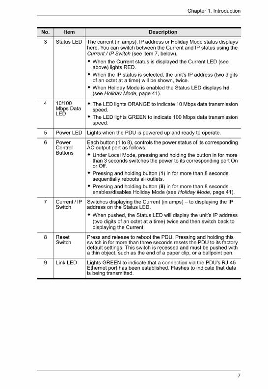
3 Status LED The current (in amps), IP address or Holiday Mode status displays here. You can switch between the Current and IP status using the Current / IP Switch (see item 7, below).
When the Current status is displayed the Current LED (see above) lights RED. When the IP status is selected, the unit’s IP address (two digits of an octet at a time) will be shown, twice. When Holiday Mode is enabled the Status LED displays hd (see Holiday Mode, page 41).
4 10/100 Mbps Data LED
The LED lights ORANGE to indicate 10 Mbps data transmission speed.The LED lights GREEN to indicate 100 Mbps data transmission speed.
5 Power LED Lights when the PDU is powered up and ready to operate.
6 Power Control Buttons
Each button (1 to 8), controls the power status of its corresponding AC output port as follows:
Under Local Mode, pressing and holding the button in for more than 3 seconds switches the power to its corresponding port On or Off.Pressing and holding button (1) in for more than 8 seconds sequentially reboots all outlets.Pressing and holding button (8) in for more than 8 seconds enables/disables Holiday Mode (see Holiday Mode, page 41).
7 Current / IP Switch
Switches displaying the Current (in amps) – to displaying the IP address on the Status LED.
When pushed, the Status LED will display the unit’s IP address (two digits of an octet at a time) twice and then switch back to displaying the Current.
8 Reset Switch
Press and release to reboot the PDU. Pressing and holding this switch in for more than three seconds resets the PDU to its factory default settings. This switch is recessed and must be pushed with a thin object, such as the end of a paper clip, or a ballpoint pen.
9 Link LED Lights GREEN to indicate that a connection via the PDU's RJ-45 Ethernet port has been established. Flashes to indicate that data is being transmitted.
No. Item Description

PE6108AV / PE6208AV / PE8208AV User Manual
8
PE6108AV / PE6208AV / PE8208AV Rear View (exclude PE6208AVX)
PE6208AVG rear view is used as the example above.
No. Item Description
1 Reset Switch
Press and release to reboot the PDU. This switch is recessed and must be pushed with a thin object, such as the end of a paper clip, or a ballpoint pen.
2 Sensor LEDs
Two Sensor LEDs light GREEN when a sensor is connected to the respective sensor port.
3 Sensor Ports
External sensors plug into these two RJ-11 ports.
4 Power Sockets
The power cables that connect to the computers plug in here.
5 Power Switch
This standard rocker switch powers the PE6108AV / PE6208AV / PE8208AV On and Off.
6 Power Socket
The power cable from the AC source plugs in here.
7 RS-232 Port
This port can be used to attach to a computer for local power on/off/reboot control.
8 LAN Port The Cat 5e cable that connects the PE6108AV / PE6208AV / PE8208AV to the Internet plugs in here.
432
7 8
5 61

Chapter 1. Introduction
9
PE6208AVX Rear View
No. Item Description
1 Reset Switch
Press and release to reboot the PDU. This switch is recessed and must be pushed with a thin object, such as the end of a paper clip, or a ballpoint pen.
2 Sensor LEDs
Two Sensor LEDs light GREEN when a sensor is connected to the respective sensor port.
3 Sensor Ports
External sensors plug into these two RJ-11 ports.
4 Power Outlet Cable Glands
Connect power of computers here. Please refer to Power Cord Installation (PE6208AVX) on page 15.
5 Power Inlet Cable Gland
Connect AC source here. Please refer to Power Cord Installation (PE6208AVX) on page 15.
6 Power Switch
This standard rocker switch powers the PE6208AVX On and Off.
7 RS-232 Port
This port can be used to attach to a computer for local power on/off/reboot control.
8 LAN Port The Cat 5e cable that connects the PE6208AVX to the Internet plugs in here.
432
7 8
5 61

PE6108AV / PE6208AV / PE8208AV User Manual
10
This Page Intentionally Left Blank

11
Chapter 2Hardware Setup
Before You Begin
Stacking and Rack Mounting
StackingThe PE6108AV / PE6208AV / PE8208AV can be placed on any appropriate level surface that can safely support its weight plus the weight of its attached cables. To place or stack the PE6108AV / PE6208AV / PE8208AV, remove the backing material from the bottom of the rubber feet that came with this package, and stick them onto the switch's bottom panel at the corners, as shown in the diagrams, below:
1. Important safety information regarding the placement of this device is provided on page 79. Please review it before proceeding.
2. Make sure that power to all the devices you will be connecting have been turned off. You must unplug the power cords of any computers that have the Keyboard Power On function.
1. Vous trouverez des informations de sécurité importantes concernant le positionnement de l’unité à la page 79. Veuillez les lire attentivement avant d’aller plus loin.
2. Vérifiez que tous les périphériques à connecter sont éteints. Vous devez débrancher les câbles d’alimentation des ordinateurs disposant de la fonction de mise sous tension à partir du clavier.

PE6108AV / PE6208AV / PE8208AV User Manual
12
:
Note: To ensure adequate ventilation, allow at least 5.1 cm on each side, and 12.7cm at the back for power cord and cable clearance.

Chapter 2. Hardware Setup
13
Rack MountingThe PE6108AV / PE6208AV / PE8208AV can be installed in most standard 19" (1U) racks. To rack mount the unit do the following:
1. Separate the front and rear modules by removing the four module attaching screws:
2. Use the screws you just removed, and the ones supplied with the rack mounting kit to screw the rack mounting brackets into both modules:
Phillips Flat Head M3 Screw * 4 pcs
Phillips hex head M3 Screw * 10 pcs
PE6108AV / PE6208AV / PE8208AV User Manual
14
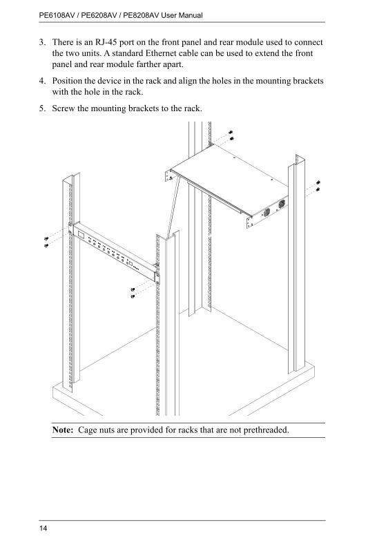
3. There is an RJ-45 port on the front panel and rear module used to connect the two units. A standard Ethernet cable can be used to extend the front panel and rear module farther apart.
4. Position the device in the rack and align the holes in the mounting brackets with the hole in the rack.
5. Screw the mounting brackets to the rack.
Note: Cage nuts are provided for racks that are not prethreaded.

Chapter 2. Hardware Setup
15
Power Cord Installation (PE6208AVX)
The PE6208AVX eco PDU provides terminal blocks that allow for custom power cord installation. Please read the following precautions before proceeding to the installation instructions.
Before InstallationWARNING! Unless you are a licensed electrician, DO NOT perform wiring assembly for this product. Assembly or attempted assembly by unlicensed electricians may result in fire, personal injury, electrical shock, and death. If you are not a qualified electrician (having appropriate licensing and insurance) - STOP NOW. ATEN is not responsible for any damages to equipment or loss of data due to improper installation.
Cord SelectionThe preferred cable is a flexible 3.0m long (max), 14 AWG cord, or a 1.5mm2, 3G flexible cord (e.g.: H05VV-F, 250V.), with a diameter of 7 - 10mm.The rated ampacity of the power cord must be greater than or equal to the product’s rated ampacity marked on its nameplate.The number of wires in the power cord must match the number of terminals (including the ground terminal).The power cord may be permanently connected to the power supply subject to local regulatory agency approval.
Plug SelectionIf a plug is to be attached to the power cord, the plug chosen should be 250V, 16A, 3C, IEC 60320 C19.For all other locations, subject to local regulatory agencies policies, the plug’s rated ampacity needs to be the same as the products rated ampacity.
PE6108AV / PE6208AV / PE8208AV User Manual
16
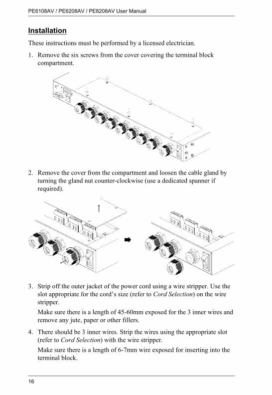
InstallationThese instructions must be performed by a licensed electrician.
1. Remove the six screws from the cover covering the terminal block compartment.
2. Remove the cover from the compartment and loosen the cable gland by turning the gland nut counter-clockwise (use a dedicated spanner if required).
3. Strip off the outer jacket of the power cord using a wire stripper. Use the slot appropriate for the cord’s size (refer to Cord Selection) on the wire stripper.Make sure there is a length of 45-60mm exposed for the 3 inner wires and remove any jute, paper or other fillers.
4. There should be 3 inner wires. Strip the wires using the appropriate slot (refer to Cord Selection) with the wire stripper.Make sure there is a length of 6-7mm wire exposed for inserting into the terminal block.

Chapter 2. Hardware Setup
17
5. Add wire ferrules to the wires.
6. Slide the power cord into the compartment through the cable gland and inner ring as shown below:
7. Open the gates of the power terminal block by loosening the screws on the top using a screwdriver. Insert the wires according to the table on the right. Tighten the screws on the top (to a torque of 0.5N.m) to secure the wires in the gates.
8. Use a dedicated spanner where necessary, tighten the cable gland by turning the gland nut clockwise (to a torque of 2-3N.m) to secure the cable to the PDU unit. Verify that the power cord is secure and cannot be twisted, pushed or pulled in the gland.

PE6108AV / PE6208AV / PE8208AV User Manual
18
9. Replace the cover and tighten the six screws to secure it to the unit.

Chapter 2. Hardware Setup
19
Installation
To install the PDU, refer to the installation diagram below (the numbers in the diagram correspond to the numbered steps), and do the following:
1. For each device you want to connect, use its power cable to connect from the device's AC socket to any available outlet on the eco PDU.For PE6208AVX, please refer to Power Cord Installation (PE6208AVX).
2. Plug the Ethernet cable into the eco PDU's LAN port to connect it to the network.
3. If you are using sensors in your eco PDU installation, connect them to the sensor ports on the unit’s rear panel.
Note: Sensors are optional. Please see Optional Accessories, page 5, and the detailed sensor installation diagrams later in this chapter for further information.
4. If you choose to use a serial device for control, connect its serial port to the PE6108AV / PE6208AV / PE8208AV's RS-232 port.
5. Connect the eco PDU's power cord to an AC power source.
Note: We strongly advise that you do not plug the eco PDU into a multi socket extension cord, since it may not receive enough amperage to operate correctly.
6. Once you have finished these installation steps, you can turn on the eco PDU and the connected devices.
Note: We strongly recommend using cable ties and cable bars to safely and securely route the cables attached to the front of the unit.

PE6108AV / PE6208AV / PE8208AV User Manual
20
PE6208AVG is the model used in the installation example picture above.
2
3 5
1
4

Chapter 2. Hardware Setup
21
Securing the CablesFor added safety, use ATEN Lok-U-Plug cable holders (not for PE6208AVX) to secure the cables from your attached devices in place on the eco PDU unit. Secure the cable holders using the specially designed holes around the individual power outlets, as shown below:
Note: 1. Cable holders are an optional accessory. See Cable Holders, page 5.
2. Use only the ATEN Lok-U-Plug cable holders that have been specifically designed to work with the eco PDU. Using any other kind of cable securing device could be highly dangerous.

PE6108AV / PE6208AV / PE8208AV User Manual
22
Securing the SensorsConnect the sensors to the eco PDU’s rear panel sensor ports and secure them using sensor mounts, tie wraps, and adhesive cable tie holders. If you use a tie wrap to secure the sensor, tighten the tie wrap over the recessed channel on the sensor, as shown in the following diagram:
Note: 1. The sensors shown in the above diagram are for reference purposes only. The sensors for the eco PDU may look slightly different.
2. Depending on the model and type of sensor, sensor mounts, tie wraps, and adhesive cable tie holders may or may not be provided in the package.

23
Chapter 3Basic Operation and
First Time Setup
Operation Methods
NRGence eco PDU models provide three methods to access and manage your installation: Browser, eco Sensors Energy Management Software and SNMP.
Note: The following sections of this chapter contain information concerning Browser operation. For eco Sensors operation, please reference the separate eco Sensors User Manual. The eco Sensors software and User Manual can be downloaded from the ATEN website.
BrowserThe eco PDU can be accessed and controlled via any supported Internet browser from any platform. See First Time Setup, page 24, and the following sections in this chapter, for full details.
eco SensorsThe eco Sensors Energy Management Software. eco Sensors provides you with an easy method for managing multiple devices, offering an intuitive and user-friendly Graphical Interface that allows you to configure a PDU device and monitor power status of the equipment connected to it. eco Sensors Energy Management Software can be downloaded from the ATEN website, along with a separate eco Sensors User Manual.
SNMPThe eco PDU supports any 3rd party V3 SNMP Manager Software. SNMP Management Information Database (MIB) files for the eco PDU device can be found on the software CD provided with the eco PDU package.
PE6108AV / PE6208AV / PE8208AV User Manual
24
First Time Setup
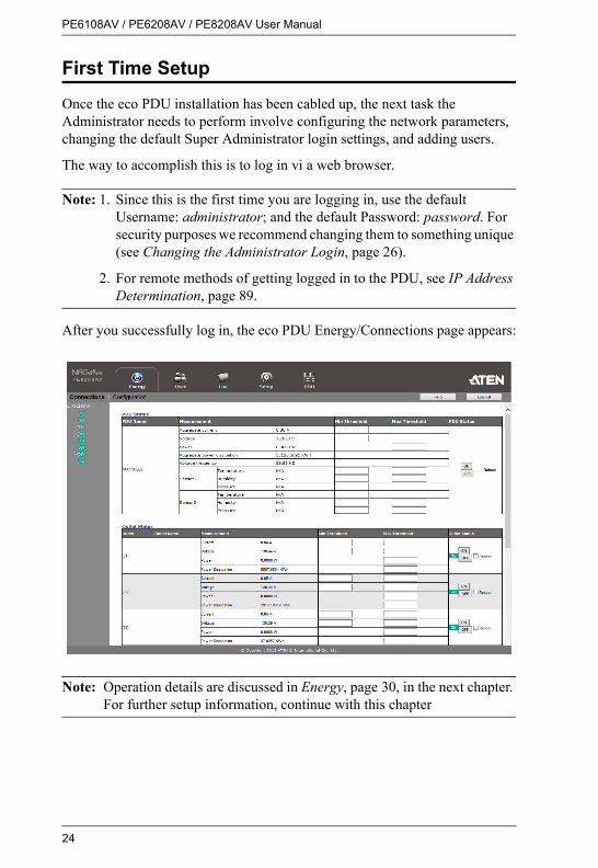
Once the eco PDU installation has been cabled up, the next task the Administrator needs to perform involve configuring the network parameters, changing the default Super Administrator login settings, and adding users.
The way to accomplish this is to log in vi a web browser.
Note: 1. Since this is the first time you are logging in, use the default Username: administrator; and the default Password: password. For security purposes we recommend changing them to something unique (see Changing the Administrator Login, page 26).
2. For remote methods of getting logged in to the PDU, see IP Address Determination, page 89.
After you successfully log in, the eco PDU Energy/Connections page appears:
Note: Operation details are discussed in Energy, page 30, in the next chapter. For further setup information, continue with this chapter

Chapter 3. Basic Operation and First Time Setup
25
Network ConfigurationTo configure the network settings, do the following:
1. Click the Setup tab.
2. The interface displays the Device Configuration page. A screen similar to the one below appears:
3. Fill in the fields according to the information provided under Device Configuration, page 47.

PE6108AV / PE6208AV / PE8208AV User Manual
26
Changing the Administrator LoginTo change the default Administrator username and password, do the following:
1. Click the User tab.The Accounts page has a detailed list of users – with more information about them – in the large central panel:
2. In the Administrator Information section, reset the name and password fields to something unique, then click Save (at the bottom of the page.)
Note: If you forget the Administrator’s name or password, short the mainboard jumper to restore the default Administrator account. See see Administrator Login Failure, page 100 in the Appendix for full details.
Moving On
After setting up the network and changing the default Administrator username and password, you can proceed to other administration activities – including adding users. This is covered in the next chapter.

27
Chapter 4Browser Operation
Logging In
The eco PDU can be accessed via a supported Internet browser from any platform.
Note: Browsers must support SSL 128 bit encryption.
To access the eco PDU do the following:
1. Open your browser and specify the IP address of the eco PDU you want to access in the browser's URL location bar.
Note: You can get the IP address from the eco PDU administrator, or see IP Address Determination, page 89, for information about setting it up yourself.
2. If a Security Alert dialog box appears, accept the certificate – it can be trusted. The Login page appears:
3. Provide a valid Username and Password (set by the administrator), and select your language. (Options are: English [default]; Traditional Chinese; Simplified Chinese; Japanese; German; Italian; Spanish; French; Russian; Korean; Portuguese).
4. Then Click Login to bring up the browser Main Page.

PE6108AV / PE6208AV / PE8208AV User Manual
28
The eco PDU Main Page
After you have successfully logged in, the eco PDU Main Page comes up with the Energy Connections page displayed:
Note: The screen depicts an Administrator’s page. Depending on a user’s type and permissions, not all of these elements appear.
Page ComponentsThe web page screen components are described in the table, below:
No. Item Description
1 Tab Bar The tab bar contains the eco PDU’s main operation categories. The items that appear in the tab bar are determined by the user’s type, and the authorization options that were selected when the user’s account was created.
2 Menu Bar The menu bar contains operational sub-categories that pertain to the item selected in the tab bar. The items that appear in the menu bar are determined by the user’s type, and the authorization options that were selected when the user’s account was created.
3 Sidebar The Sidebar provides a tree view listing of outlets that relate to the various tab bar and menu bar selections.

Chapter 4. Browser Operation
29
4 Help Connects to on-line help at the ATEN website for the device’s configuration and operation.
5 Logout Click this button to log out of your eco PDU session.
6 Interactive Display Panel This is your main work area. The screens that appear reflect your menu choices and Sidebar node selection.
No. Item Description

PE6108AV / PE6208AV / PE8208AV User Manual
30
Energy
ConnectionsWhen you log in to the eco PDU, the interface opens with its default selection of the Energy tab; and the Connections menu. The contents of the PDU Status and Outlet Status sections are displayed in the main panel.
Note: Only enabled eco PDU models will display the Outlet Status submenu section. Other models provide only PDU Status monitoring. See Features, page 3, for which models support PDU and Outlet Status or PDU Status only monitoring.

Chapter 4. Browser Operation
31
PDU StatusAll eco PDU models support PDU device level monitoring. The PDU Status section allows you to set up a power management configuration for the PDU device as a whole:
PDU Threshold Settings These fields are used to set the maximum, minimum, and fluctuation threshold settings for Aggregate Current, Voltage, Power, and Aggregate Power Dissipation. If a range falls below the minimum setting, or exceeds the maximum setting an alarm is triggered. The Aggregate Current Max Threshold setting triggers the Proactive Overload Protection (POP) mode (see page 34).
Voltage Frequency is displayed here in Hz.On / Off / RebootYou can manually turn the device On and Off from this page by clicking the radio buttons. To Reboot the device, enable the Reboot checkbox and click on Save (located at the bottom of the page).
Sensor 1 / Sensor 2If you have sensors installed in your installation, use these fields to set the maximum, minimum and fluctuation threshold settings for Temperature, Humidity, and Differential Pressure.
Note: Sensors are optional accessories. Check with your dealer for information about NRGence eco Sensors software.

PE6108AV / PE6208AV / PE8208AV User Manual
32
Outlet Status (PE6208AV)The PE6208AV supports on, off and reboot control from the outlet status column for each outlet.
On / Off / Reboot You can manually turn the outlet On and Off from this page by clicking the radio buttons. To Reboot the outlet, enable the Reboot checkbox and click on Save (located at the bottom of the page).
Chapter 4. Browser Operation
33
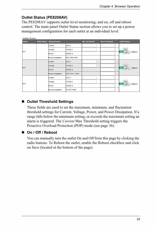
Outlet Status (PE8208AV)The PE8208AV supports outlet level monitoring; and on, off and reboot control. The main panel Outlet Status section allows you to set up a power management configuration for each outlet at an individual level.
Outlet Threshold SettingsThese fields are used to set the maximum, minimum, and fluctuation threshold settings for Current, Voltage, Power, and Power Dissipation. If a range falls below the minimum setting, or exceeds the maximum setting an alarm is triggered. The Current Max Threshold setting triggers the Proactive Overload Protection (POP) mode (see page 36).
On / Off / Reboot You can manually turn the outlet On and Off from this page by clicking the radio buttons. To Reboot the outlet, enable the Reboot checkbox and click on Save (located at the bottom of the page).

PE6108AV / PE6208AV / PE8208AV User Manual
34
Configuration (PE6208AV)The Configuration page is used to configure the settings of the PE6208AV at the individual power outlet level.
POP SettingsThis section allows you to enable Proactive Overload Protection (POP). Proactive Overload Protection is triggered when the PDU’s Aggregate Current Max Threshold setting is exceeded (see page 31). Effective on all outlets, this added safety feature automatically powers off the outlets according to the settings below:
Enable Bank POP Priority Mode checking this box enables Proactive Overload Protection and will power off outlets according to the Bank POP Priority List (see page 35).
Power On Time Schedule SettingsCheck the Enable Power On Time Schedule box to use the Power ON Delay setting to set the amount of time the eco PDU waits before powering on an outlet. See Power ON Delay in the table on the next page.
Buzzer Setting Checking the Enable Buzzer Alarm box sounds an alarm and sends SNMP trap or e-mail alerts when a threshold setting exceeds the minimum or maximum setting.
Outlet Reboot SettingChecking the Enable Outlet Sequential Reboot box allows you to sequentially reboot all outlets by pressing the Power Control Button of Outlet 1 for more than 8 seconds.

Chapter 4. Browser Operation
35
Bank POP Priority List Use the eight drop-down menus to set the priority for when Proactive Overload Protection powers off the outlets. The outlet set as Priority1 will be powered off first, Priority2 will be powered off second, and so on. Outlets set to N/A will not be powered off when Proactive Overload Protection is triggered.
To change the Priority List, set at least two drop-down menus to N/A. Outlets set to N/A become available for selection in the Priority drop-down menus. An easy way to reconfigure all outlets is to set all drop-down menus to N/A and then go back select an outlet for each Priority1~8 setting. Outlets set to N/A will not be powered off when Proactive Overload Protection is triggered.

PE6108AV / PE6208AV / PE8208AV User Manual
36
Configuration (PE8208AV)The Configuration page is used to configure the settings of the PE8208AV at the individual power outlet level:
POP SettingsThis section allows you to enable Proactive Overload Protection (POP). Proactive Overload Protection is triggered when a PDU’s or Outlet’s Current Max Threshold setting is exceeded. Effective on all outlets, this added safety feature automatically powers off outlets according to the settings below:
Enable Outlet POP checking this box triggers Proactive Overload Protection to power off an outlet when it’s Current Max Threshold setting is exceeded (see page 33). Enable Bank POP LIFO Mode checking this box triggers Proactive Overload Protection to power off a newly inserted device (LIFO), when it causes the PDU’s Aggregate Current Max Threshold setting to be exceeded (see page 31). All other outlets stay powered on. Enable Bank POP Priority Mode checking this box triggers Proactive Overload Protection when the PDU’s Aggregate Current Max Threshold setting is exceeded (see page 31). This will power off outlets according to the Bank POP Priority List settings (see page 37).For more information about how the POP Settings work together, see POP Setting Scenarios, page 38.

Chapter 4. Browser Operation
37
Power On Time Schedule SettingsCheck the Enable Power On Time Schedule box to use the Power ON Delay setting to set the amount of time the eco PDU waits before powering on an outlet. See Power ON Delay in the table on the next page.
Buzzer Setting Checking the Enable Buzzer Alarm box sounds an alarm and sends SNMP trap or e-mail alerts when a threshold setting exceeds the minimum or maximum setting.
Outlet Reboot SettingChecking the Enable Outlet Sequential Reboot box allows you to sequentially reboot all outlets by pressing the Power Control Button of Outlet 1 for more than 8 seconds.
Bank POP Priority List Use the eight drop-down menus to set the priority for when Proactive Overload Protection powers off the outlets. The outlet set as Priority1 will be powered off first, Priority2 will be powered off second, and so on. Outlets set to N/A will not be powered off when Proactive Overload Protection is triggered.
To change the Priority List, set at least two drop-down menus to N/A. Outlets set to N/A become available for selection in the Priority drop-down menus. An easy way to reconfigure all outlets is to set all drop-down menus to N/A and then go back select an outlet for each Priority1~8 setting. Outlets set to N/A will not be powered off when Proactive Overload Protection is triggered.

PE6108AV / PE6208AV / PE8208AV User Manual
38
POP Setting Scenarios
Setting Description
A Triggers Proactive Overload Protection to power off an outlet when it's Current Max Threshold setting is exceeded. Only the outlet that exceeds the threshold setting is powered off.
B Triggers setting A and: Triggers Proactive Overload Protection to shut off power to a newly inserted device (LIFO), when it causes the PDU’s Aggregate Current Max Threshold setting to be exceeded. Only the outlet with a newly inserted device is powered off; all other outlets stay on. If another outlet exceeds the Aggregate Current threshold, an alarm is triggered.
C Triggers setting A and:Triggers Proactive Overload Protection when the PDU’s Aggregate Current Max Threshold setting is exceeded and shuts off power to the (LIFO) outlet first, and then the remaining outlets in order, according to the Bank POP Priority List. Any outlet set to N/A will not be powered off.
D Triggers setting A and:Triggers Proactive Overload Protection when the PDU’s Aggregate Current Max Threshold setting is exceeded to power off outlets according to the Bank POP Priority List. Any outlet set to N/A will not be powered off.

Chapter 4. Browser Operation
39
Outlet Configuration
The Outlet Configuration section lets you set the power management settings for each outlet on the PDU.
Heading Meaning
Outlet Shows the port number of the listed outlet.
Outlet Name Each outlet can be given a distinctive name. The maximum number of characters is 15.
Confirmation Required
If this option is enabled (there is a check in the checkbox), a dialog box comes up asking you to confirm a power operation before it is performed. If it is disabled (there is no check in the checkbox), the operation is performed without confirmation.
Outlet Locked Check this box to disable use of the front panel Power Control Button for the outlet. When you check the box the outlet’s Local LED turns off and the Power Control Button will no longer reboot the outlet. Note: Uncheck the box to enable Local Mode.

PE6108AV / PE6208AV / PE8208AV User Manual
40
Delay Time (sec) Power ON
Sets the amount of time the eco PDU waits after the Power Button is clicked (see Outlet Status (PE6208AV), page 32), before it turns on the power to the outlet. You must check the Enable Power On Time Schedule Setting box for this setting to take effect. See Power On Time Schedule Settings, page 34, for details. Note: The default delay time is 0 seconds; the maximum is 999 seconds. When a series of outlets are scheduled to be powered up, they turn on in sequence with a default delay of 10 milliseconds between each outlet.
Delay Time (sec) Power OFF
Sets the amount of time the eco PDU waits after the Power Button is clicked (see Outlet Status (PE6208AV), page 32), before it turns off the power to the outlet.For the System after AC Back option (see below), after the delay time expires, the eco PDU waits another fifteen seconds, then shuts the computer down.The default delay time is 15 seconds. The maximum delay time is 999 seconds.
Remote Turn ON Method
Use the drop-down menu to select one of the choices, below:Wake on LAN: This is a Safe Shutdown and Restart option. If this
is selected, when an Outlet is turned Off, the eco PDU first sends a message to the computer telling it to prepare for a shutdown; it then waits for the amount time set in the Power Off Delay field to give the OS time to close down before the computer is powered down to standby mode.Likewise, when the Outlet is turned On, the eco PDU waits for the amount time set in the Power On Delay field, then sends an Ethernet message to the computer connected to the Outlet telling the computer to turn itself On.Note: For Safe Shutdown and Restart, the computer must be running Windows (98 or higher), or Linux, and the Safe Shutdown program (available by download from our website), must be installed and running on the computer.
System after AC Back: This is a Safe Shutdown and Restart option. If this is selected, when an Outlet is turned Off, the eco PDU first sends a message to the computer telling it to prepare for a shutdown; it then waits for the amount time set in the Power Off Delay field to give the OS time to close down before the computer is powered down.When the Outlet is turned On, the eco PDU waits for the amount time set in the Power On Delay field, then sends power to the server. When the server receives the power, it turns itself on.Note: For Safe Shutdown and Reboot, the computer must be running Windows (98 or higher), or Linux, and the Safe Shutdown program (available by download from our website), must be installed and running on the computer.
Kill the Power: If this option is selected, the eco PDU waits for the amount time set in the Power Off Delay field, and then turns the Outlet's power Off. Turning the power off performs a cold (non-safe) shutdown.
Heading Meaning

Chapter 4. Browser Operation
41
When you have finished making your configuration settings, click Save.
MAC Address In order to use either of the Safe Shutdown and Restart methods the MAC address of the computer connected to the outlet must be filled in here.
Auto Ping Method Auto Ping Method pings a device at specified intervals and if there is no response (Request timed out) the PDU automatically powers cycles the outlet (off and then on).Config: Use this drop-down menu to select the type of device you
want to ping:
Sky/SkyHD/SkyQ (DLNA) will auto configure the Method and Port settings and they cannot be changed.
Use Other to ping any other network device.
Method: Use the drop-down menu to select:
None to disable Auto Ping Method.
Ping to ping a specified IP address.
Telnet to ping the port of a specified IP address.
Interval Time: Enter the number of minutes to elapse between each auto-ping that is sent to test the network device.
Retries: Enter the number of power cycles to attempt if the device cannot be pinged after the initial power cycle. If the device still cannot be pinged after the specified number of retries, the PDU will stop pinging the device and shut off the outlet. To restart Auto Ping Method, you must set the Auto Ping Method to None, reselect Ping or Telnet, and then power on the outlet.
IP Address: Enter the IP address of the device you want to ping.Port: Enter the port number of the device you want Telnet to ping.
This option is available when Telnet is selected.
Holiday Mode Use this drop-down menu to select the outlet’s Holiday Mode. When Holiday Mode is enabled, each outlet will be set to the selection chosen for it: POWER OFF or POWER ON. When Holiday Mode is disabled, the outlets return to the outlet status setting before Holiday Mode was enabled.To enable/disable Holiday Mode, press and hold Power Control Button (8) in for more than 8 seconds. This is a toggle setting.
Heading Meaning
PE6108AV / PE6208AV / PE8208AV User Manual
42
User
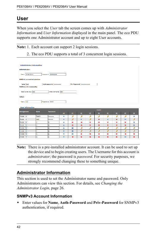
When you select the User tab the screen comes up with Administrator Information and User Information displayed in the main panel. The eco PDU supports one Administrator account and up to eight User accounts.
Note: 1. Each account can support 2 login sessions.
2. The eco PDU supports a total of 3 concurrent login sessions.
Note: There is a pre-installed administrator account. It can be used to set up the device and to begin creating users. The Username for this account is administrator; the password is password. For security purposes, we strongly recommend changing these to something unique.
Administrator InformationThis section is used to set the Administrator name and password. Only Administrators can view this section. For details, see Changing the Administrator Login, page 26.
SNMPv3 Account InformationEnter values for Name, Auth-Password and Priv-Password for SNMPv3 authentication, if required.

Chapter 4. Browser Operation
43
SNMPv1/v2c CommunityEnter values Read community and Write community for SNMPv1/V2c authentication, if required.
TelnetUse the Name and Password fields to change the account used to login via Telnet sessions.
Click Save to save your settings.
User InformationTo add a user, do the following:
1. Select the Enable or Disable in the Management drop-down menu.
2. Key in a name and password in the Name and Password fields.
3. Set the outlet-by-outlet permissions of the user in the Outlet field.
4. Click Save to save your settings.
Note: Values must be entered in both the Name and Password fields in order to enable an account.
The various options are explained in more detail in the following table:
Field Description
Management The Management field allows you to Enable or Disable a user’s account:
Enable – stores the user account (see User Information, page 43
Disable – disables the user account
Name From 1 to 16 characters are allowed depending on the Account Policy settings. See Account Policy, page 56.
Password From 1 to 16 characters are allowed depending on the Account Policy settings. See Account Policy, page 56.
PE6108AV / PE6208AV / PE8208AV User Manual
44
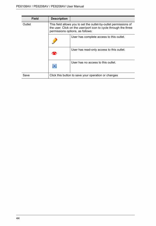
Outlet This field allows you to set the outlet-by-outlet permissions of the user. Click on the user/port icon to cycle through the three permissions options, as follows:
User has complete access to this outlet.
User has read-only access to this outlet.
User has no access to this outlet.
Save Click this button to save your operation or changes
Field Description

Chapter 4. Browser Operation
45
Log
The Log tab keeps a record of transactions that take place on its installation, and stores up to 128 events at one time. The System Log page provides a powerful array of filters and functions that allow you to view and export the log file data, as well as be informed by email of specified events as they occur.
The System Log Event ListClicking on a device in the Sidebar displays its log events in the main panel’s log event list.Clicking the Refresh button brings the log list up to date with the latest events.The entry box to the right of the Refresh button lets you set the number of events to display per page. Simply key in the number of your choice.The top right of the main panel shows the total number of pages in the log file, and what page you are currently viewing.The buttons on the bottom row function as follows:
Clear – click to erase the contents of the log event listFirst Page – click to go to the first page of the log event listPrevious Page – click to move to the previous page of the log event listNext Page – click to move to the next page of the log event listLast Page – click to move to the last page of the log event listExport Log – click to save the contents of the log event list to file.

PE6108AV / PE6208AV / PE8208AV User Manual
46
Notification SettingsThe Notification Settings page is used to specify which of the eco PDU’s components will receive notification of a log event. When you click the Notification Settings menu item, a page similar to the one below appears:
The event categories are listed in the left column.When you first open the page, only the main category items appear. (Main category item rows have a gray background.)Sub-category items are nested under the main category headings. Click the arrow in front of the main category headings to display the subcategory items. (Sub-category item rows have a white background.)
Click the checkboxes under the column headings to select which component(s) will receive notification of the log events.
Clicking on a main category heading’s row automatically selects all the sub-category items nested below it.If you only want to set notification for some of the sub-category events, don’t put a check in the main category row. Instead, drop down the sub-category list, and only check the sub-category events you want.
When you have finished making your setting choices, click Save. When a specified log event occurs, notification of that event will be sent to the selected component.Reset Digital Output: If an event has been triggered that changes the digital output sensor from Low to High, click this button to return the sensor to the Low state.

Chapter 4. Browser Operation
47
Setup
The Setup tab provides Device Configuration and Security settings. The Device Configuration page allows administrators to configure eco PDU system settings. The Security page controls access to the PDU.
Device ConfigurationThis page presents information about the selected device, as described in the following sections:
General
Item Meaning
PDU Name This field lets you give the device a unique name. Simply delete whatever is in the text box and key in the name of your choice. Click Save (located at the bottom of the page) to save the new name.
MAC Address This item displays the eco PDU’s MAC address.
Firmware Version This item displays the current firmware version number. You can reference it to see if there are newer versions available on the NRGence website.
Rack Location Name
This field lets you give the rack location a unique name for easy reference.
PE6108AV / PE6208AV / PE8208AV User Manual
48
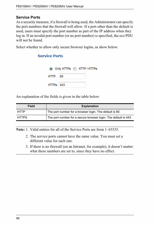
Service PortsAs a security measure, if a firewall is being used, the Administrator can specify the port numbers that the firewall will allow. If a port other than the default is used, users must specify the port number as part of the IP address when they log in. If an invalid port number (or no port number) is specified, the eco PDU will not be found.
Select whether to allow only secure browser logins, as show below:
An explanation of the fields is given in the table below:
Note: 1. Valid entries for all of the Service Ports are from 1–65535.
2. The service ports cannot have the same value. You must set a different value for each one.
3. If there is no firewall (on an Intranet, for example), it doesn’t matter what these numbers are set to, since they have no effect.
Field Explanation
HTTP The port number for a browser login. The default is 80.
HTTPS The port number for a secure browser login. The default is 443.

Chapter 4. Browser Operation
49
IPv4 ConfigurationThe PDU’s IPv4 IP and DNS addresses (the traditional method of specifying IP addresses) can either be assigned dynamically (DHCP), or a fixed IP address can be specified.
For dynamic IP address assignment, select the Obtain IP address automatically radio button. (This is the default setting.)To specify a fixed IP address, select the Set IP address manually radio button and fill in the IP address with values appropriate for your network.For automatic DNS Server address assignment, select the Obtain DNS Server address automatically radio button.To specify the DNS Server address manually, select the Set DNS server address manually radio button, and fill in the addresses for the Preferred and Alternate DNS servers with values appropriate for your network.
Note: 1. If you choose Obtain IP address automatically, when the device starts up it waits to get its IP address from the DHCP server. If it hasn’t obtained the address after one minute, it automatically reverts to its factory default IP address (192.168.0.60.)
2. If the device is on a network that uses DHCP to assign network addresses, and you need to ascertain its IP address, see IP Address Determination, page 89, for information.
3. Specifying the Alternate DNS Server address is optional.

PE6108AV / PE6208AV / PE8208AV User Manual
50
Event NotificationThe Event Notification section is divided into three sections: SMTP Server; SNMP Trap Receivers; and Syslog Server. Each section is described below.
SMTP Server
To have the eco PDU email reports from the SMTP server to you, do the following:
1. Enable the Enable report from the following SMTP Server, and key in the IP address and Port number of your SMTP server.
2. If your server requires authentication, put a check in the My server requires authentication checkbox.
3. Key in the appropriate account information in the Account Name, Password, and From fields.
Note: Only one email address is allowed in the From fields, and it cannot exceed 64 characters.
4. Key in the email address (addresses) of where you want the event reports sent to in the To field.
Note: If you are sending the report to more than one email address, separate the addresses with a semicolon. The total cannot exceed 256 characters.

Chapter 4. Browser Operation
51
SNMP Trap Receivers
Up to four SNMP management stations can be specified. If you want to use SNMP trap notifications, do the following:
1. Check Enable SNMP Trap.
2. Select which version of SNMP you want to use.
3. Key in the IP address(es) and the service port number(s) of the computer(s) to be notified of SNMP trap events. The valid port range is 1–65535. The default port number is 162.
Note: Make sure that the port number you specify here matches the port number used by the SNMP receiver computer.
4. Key in the community value(s) if required for the SNMP version.
5. Key in the auth/privacy password(s) that correspond to each of the stations.

PE6108AV / PE6208AV / PE8208AV User Manual
52
Syslog Server
To record all the events that take place on eco PDU devices and write them to the eco PDU Syslog server, do the following:
1. Check Enable Syslog Server.
2. Key in the IP address and the port number of the Syslog server. The valid port range is 1-65535. The default port number is 514.

Chapter 4. Browser Operation
53
Date/TimeThe Date/Time dialog page sets the eco PDU time parameters:
Time ZoneTo establish the time zone that the eco PDU is located in, drop down the Time Zone list and choose the city that most closely corresponds to where it is at.If your country or region employs Daylight Saving Time (Summer Time), check the corresponding checkbox.

PE6108AV / PE6208AV / PE8208AV User Manual
54
Manual InputUse this section to specify the eco PDU’s date and time manually.
Click the calendar icon and click the calendar entry for the date.Key the time into the Time field, using the HH:MM:SS (hours, minutes, seconds) format.
Note: This section is only enabled when auto adjustment (in the Network Time section) is disabled (the checkbox is unchecked).
As an alternative to specifying the date and time by entering them into the date and time fields, you can click to put a check in the Sync with PC checkbox, in which case the eco PDU will take its date and time settings from the locally connected PC.
Network TimeTo have the time automatically synchronized to a network time server, do the following:
1. Check the Enable auto adjustment checkbox.
2. Drop down the time server list to select your preferred time server– or –
Check the Preferred custom server IP checkbox, and key in the IP address of the time server of your choice.
3. If you want to configure an alternate time server, check the Alternate time server checkbox, and repeat step 2 for the alternate time server entries.
4. Key in your choice for the number of days between synchronization procedures.
Finishing UpWhen you have finished making your settings on this page, click Save.
After you have saved your changes, if you want to synchronize immediately, click Adjust Time Now.

Chapter 4. Browser Operation
55
SecurityThe Security page controls access to the eco PDU device.
Login FailuresAllowed sets the number of consecutive failed login attempts that are permitted from a remote user.Timeout sets the amount of time a remote user must wait before attempting to login again after exceeding the number of allowed failures.
Working ModeIf Enable ICMP is checked, the eco PDU device can be pinged. If it is not enabled, the device cannot be pinged. The default is Enabled.If Enable Telnet Server is checked, the PDU is accessible via a Telnet sessions using the Telnet username and password (see Telnet, page 43)
Session TimeoutIf Enable Web Session Timeout in is checked, a user's web session will logout due to inactivity after the number of Minute(s) entered (1–5) is surpassed.
When you have finished making your settings on this page, click Save.

PE6108AV / PE6208AV / PE8208AV User Manual
56
Account PolicyThe Account Policy section governs policies in regard to usernames and passwords.
Check a policy and enter the required information in the appropriate fields.
Item DescriptionMinimum Username Length Sets the minimum number of characters required for
a username. Acceptable values are from 1–16.Minimum Password Length Sets the minimum number of characters required for
a password. Acceptable values are from 1–16.Password Must Contain At Least Checking any of these items requires users to include
at least one of the specified items in their password.Note: This policy does not affect existing user accounts. Only new user accounts created after this policy has been enabled, and users required to change their passwords are affected.
Disable Duplicate Login Check this to prevent users from logging in with the same account at the same time.

Chapter 4. Browser Operation
57
Login String / IP Filter / Mac Filter
Login StringThe Login String entry field is used to specify a login string (in addition to the IP address) that users must include when accessing the eco PDU device with a browser. For example:
192.168.0.126/abcdefg
The following characters are allowed:0–9 a–z A–Z ~ ! @ $ * ( ) _ ‘ ,
The following characters are not allowed:& ^ { } ‘ ’ < > | " % ” : / ? # \ [Space] + - = [ ] ;
Compound characters (É Ç ñ ... etc.)
Note: 1. There must be a forward slash between the IP address and the string.
2. If no login string is specified here, anyone will be able to access the eco PDU device login page using the IP address alone. This makes your installation less secure.
For security purposes, we recommend that you change this string occasionally.

PE6108AV / PE6208AV / PE8208AV User Manual
58
IP Filter / MAC Filter
If any filters have been configured, they appear in the IP Filter and/or MAC Filter list boxes.
IP and MAC Filters control access to the eco PDU based on the IP and/or MAC addresses of the client computers attempting to connect. A maximum of 5 IP filters and 5 MAC filters are allowed.
To enable IP and/or MAC filtering, click to put a check mark in the IP Filter Enable and/or MAC Filter Enable checkbox.
If the include button is checked, all the addresses within the filter range are allowed access; all other addresses are denied access.If the exclude button is checked, all the addresses within the filter range are denied access; all other addresses are allowed access.
Adding FiltersTo add an IP filter, do the following:
1. Click Add. A dialog box similar to the one below appears:
2. Specify the start filter address in the dialog box (for example, 192.168.0.200), then click OK.
3. To filter a single IP address, key in the same address as the start IP. To filter a continuous range of addresses, key in the end number of the range (for example, 192.168.0.225).
4. After filling in the address, click OK.
Repeat these steps for any additional IP addresses you want to filter.

Chapter 4. Browser Operation
59
To add a MAC filter, do the following:
1. Click Add. A dialog box similar to the one below appears:
2. Specify the MAC address in the dialog box (for example, 001074670000), then click OK.
Repeat these steps for any additional MAC addresses you want to filter.
IP Filter / MAC Filter ConflictIf there is a conflict between an IP filter and a MAC filter – for example, where a computer’s IP address is allowed by the IP filter but its MAC address is excluded by the MAC filter – then that computer’s access is blocked.
In other words, if either filter blocks a computer, then the computer is blocked, no matter what the other filter is set to.
Modifying FiltersTo modify a filter, select it in the IP Filter or MAC Filter list box and click Modify. The Modify dialog box is similar to the Add dialog box. When it comes up, simply delete the old address(es) and replace it with the new one(s).
Deleting FiltersTo delete a filter, select it in the IP Filter or MAC Filter list box and click Delete.

PE6108AV / PE6208AV / PE8208AV User Manual
60
Authentication & AuthorizationThe Authentication & Authorization page is used to set up login authentication and authorization management from external sources.
RADIUS Settings
To allow authentication and authorization for the eco PDU device through a RADIUS server, do the following:
1. Check Enable.
2. Fill in the IP addresses and service port numbers for the Preferred and Alternate RADIUS servers. The default port number for the Preferred server is 1812; the default port number for the Alternate server is 1645.
Note: Make sure that the port numbers you specify here match the port numbers used by the RADIUS servers.
3. In the Timeout field, set the time in seconds that the eco PDU device waits for a RADIUS server reply before it times out.
4. In the Retries field, set the number of allowed retries for attempting to connect to the RADIUS server.
5. In the Shared Secret field, key in the character string that you want to use for authentication between the eco PDU device and the RADIUS Server.

Chapter 4. Browser Operation
61
6. On the RADIUS server, set the entry for each user as follows:
su/administrator or su/user
Where xxxx represents the Username given to the user when the account was created on the eco PDU device. The user’s access rights are the ones assigned for the eco PDU device, as well. (See User Information, page 43.)
Note: su/user supports view ports only; su/administrator supports all eco PDU functions.
Private CertificateWhen logging in over a secure (SSL) connection, a signed certificate is used to verify that the user is logging in to the intended site. For enhanced security, the Private Certificate section allows you to use your own private encryption key and signed certificate, rather than the default ATEN certificate.
There are two methods for establishing your private certificate: generating a self-signed certificate; and importing a third-party certificate authority (CA) signed certificate.
Generating a Self-Signed CertificateIf you wish to create your own self-signed certificate, a free utility – openssl.exe – is available for download over the web.
Obtaining a CA Signed SSL Server CertificateFor the greatest security, we recommend using a third party certificate authority (CA) signed certificate. To obtain a third party signed certificate, go to a CA (Certificate Authority) website to apply for an SSL certificate. After the CA sends you the certificate and private encryption key, save them to a convenient location on your computer.
(Continues on next page.)

PE6108AV / PE6208AV / PE8208AV User Manual
62
Importing the Private CertificateTo import the private certificate, do the following:
1. Click Browse to the right of Private Key; browse to where your private encryption key file is located; and select it.
2. Click Browse to the right of Certificate; browse to where your certificate file is located; and select it.
3. Click Upload to complete the procedure.
Note: 1. Clicking Restore Default returns the device to using the default ATEN certificate.
2. Both the private encryption key and the signed certificate must be imported at the same time.
When you have finished making your settings on this page, click Save.

Chapter 4. Browser Operation
63
PDU
The PDU tab is used to upgrade the eco PDU’s firmware, and to backup and restore the device’s configuration settings.
Firmware FileWhen you click the Maintenance tab, the display opens with the Firmware Upgrade menu page, which looks similar to the one below:
A description of the items shown in this panel are given in the table, below:
Item Description
Check Main Firmware Version
If you enable Check Main Firmware Version, the eco PDU’s current firmware level is compared with that of the upgrade file. If the current version is equal to or higher than the upgrade version, a popup message appears, to inform you of the situation and stops the upgrade procedure.
Name Lists all of the eco PDU devices. Click to put a check in the checkbox of the device’s whose firmware you want to upgrade.
F/W Version Displays the eco PDU’s current firmware version.
Filename As new versions of the firmware become available, they are posted on our website and can be downloaded to a convenient location on your computer. Click the Browse button to select the downloaded upgrade file.
Upgrade Click this button to upgrade the firmware of the selected devices.

PE6108AV / PE6208AV / PE8208AV User Manual
64
Upgrading the FirmwareTo upgrade the firmware refer to the screenshot on the preceding page, and do the following:
1. Go to our website and download the new firmware file to a convenient location on your computer.
2. Click the Browse button; navigate to where the firmware file is located and select it.
3. Click Upgrade to start the upgrade procedure.If you enabled Check Main Firmware Version the current firmware level is compared with that of the upgrade file. If the current version is equal to or higher than the upgrade version, a popup message appears, to inform you of the situation and stops the upgrade procedure.If you didn't enable Check Main Firmware Version, the upgrade file is installed without checking what its level is.Once the upgrade completes successfully, the switch resets itself.
4. Log in again, and check the firmware version to be sure it is the new one.
Firmware Upgrade RecoveryShould the eco PDU’s firmware upgrade procedure fail, and the device becomes unusable, the following firmware upgrade recovery procedure will resolve the problem:
1. Power off the device.
2. Press and hold the Reset Switch in (see page 7).
3. While holding the Reset Switch in, power the switch back on.
This causes the switch to use the original factory installed main firmware version. Once the switch is operational, you can try upgrading the main firmware again.

Chapter 4. Browser Operation
65
Backup/RestoreSelecting Backup/Restore on the menu bar gives you the ability to back up the switch’s configuration and user profile information:
BackupTo backup the device’s settings do the following:
1. In the Password field, key in a password for the file.
Note: Entering a password is optional. If you do enter a password, make a note of it, since you will need it to be able to restore the file.
2. Click Save.
3. When the browser asks what you want to do with the file, select Save to disk; then save it in a convenient location.
RestoreTo restore a previous backup, do the following:
1. Click Browse; navigate to the file and select it.
Note: If you renamed the file, you can leave the new name. There is no need to return it to its original name.
2. In the Password field, key in the same password that you used to save the file.
Note: If you did not set a password when you created the backup file, you can omit this step.
3. Select as many of the options that are presented as you wish to restore.
4. Click Restore.After the file is restored, a message appears to inform you that the procedure succeeded.

PE6108AV / PE6208AV / PE8208AV User Manual
66
This Page Intentionally Left Blank
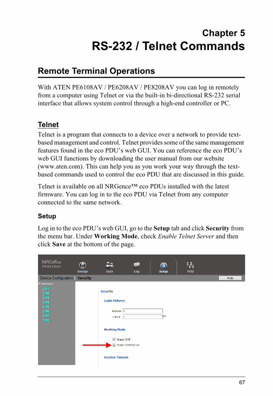
67
Chapter 5RS-232 / Telnet Commands
Remote Terminal Operations
With ATEN PE6108AV / PE6208AV / PE8208AV you can log in remotely from a computer using Telnet or via the built-in bi-directional RS-232 serial interface that allows system control through a high-end controller or PC.
TelnetTelnet is a program that connects to a device over a network to provide text-based management and control. Telnet provides some of the same management features found in the eco PDU’s web GUI. You can reference the eco PDU’s web GUI functions by downloading the user manual from our website (www.aten.com). This can help you as you work your way through the text-based commands used to control the eco PDU that are discussed in this guide.
Telnet is available on all NRGence™ eco PDUs installed with the latest firmware. You can log in to the eco PDU via Telnet from any computer connected to the same network.
Setup
Log in to the eco PDU’s web GUI, go to the Setup tab and click Security from the menu bar. Under Working Mode, check Enable Telnet Server and then click Save at the bottom of the page.

PE6108AV / PE6208AV / PE8208AV User Manual
68
Note: If the Enable Telnet Server option is not available, please download the latest firmware from our website.
Logging InTo log in to the eco PDU via Telnet, do the following:
1. On your computer, open the start menu and select Run. Type: cmd
Click OK.
2. At the command prompt, key in telnet and the IP Address of the PDU, as follows:
telnet [IP Address]
3. Press Enter. The login screen appears:
4. At the login prompt, enter Username: teladmin; and Password: telpwd.
Note: The Telnet username and password can be configured on the User tab of the eco PDU's web GUI.
5. When the Telnet session is established, Logged in successfully appears along with the command line prompt:

Chapter 5. RS-232 / Telnet Commands
69
RS-232 Serial ControlThis section provides the serial control settings and PIN assignments used to configure the RS-232 Serial Port.
RS232 Pin Assignment
Configuring the Serial PortThe controller’s serial port should be configured as follows:
Pin Description Pin Description
1 Not connected 6 Not connected
2 RXD 7 Not connected
3 TXD 8 Not connected
4 Not connected 9 Not connected
5 GND
RS-232 Serial Control Protocol Settings
Baud Rate 115200 (Default)
Data Bit 8 bits
Parity None
Stop Bit 1 Bit
Flow Control None

PE6108AV / PE6208AV / PE8208AV User Manual
70
Commands
Use the Telnet and RS-232 text commands to view and configure the eco PDU as described in each section. The text-based command line provides some of the same functions found under the Energy tab of the eco PDU’s web-based GUI. Commands to view and configure the eco PDU are provide in the following sections. You can reference information provided in the user manual for the functions as you use the commands.
VerificationAfter sending an incorrect command, a verification message appears at the end of the command line.
Invalid command or exceed max command length - the command has the wrong format and/or values. Try typing in the command string again using the correct format and/or values.

Chapter 5. RS-232 / Telnet Commands
71
Read Outlet StatusThe Read Outlet Status command allows you to view the power status of an outlet on the eco PDU.
The formula for Read Outlet Status commands is as follows:Command + Outlet + Number + Return String + [Enter]
1. For example, if you want to read the status of outlet 01 with a simple return string, type the following:read status o01 simple [Enter]
2. For example, if you want to read the status of outlet 12 with a format return string, type the following:read status o12 format [Enter]
The following tables show the possible values for the Read Outlet Status commands:
The following table lists the available Read Outlet Status commands:
Command Description
read status Read status command
Outlet Description
o Outlet command
xx PDU Outlet numberxx: Outlet on PDUExample: o02
Return String Description
simple Return simple string status
format Return format string status
Command Outlet Return String Enter Description
read status oXX simple [Enter] Read the status of outlet XX with a simple return string. XX: Outlet number
read status oXX format [Enter] Read the status of outlet XX with a format return string. XX: Outlet number

PE6108AV / PE6208AV / PE8208AV User Manual
72
Note: 1. Each command string can be separated with a space.
2. The Return String command string can be skipped and format will be used by default.

Chapter 5. RS-232 / Telnet Commands
73
Switch Outlet StatusThe Switch Outlet Status command allows you to change the power status of an outlet on the eco PDU.
The formula for Switch Outlet Status commands is as follows:Command + Outlet + Number + Control + Option + [Enter]
1. For example, if you want to switch off outlet 04 immediately, type the following:sw o04 off imme [Enter]
2. For example, if you want to switch on outlet 12 with the time delay set for the outlet, type the following:sw o12 on delay [Enter]
3. For example, if you want to reboot outlet 08, type the following:sw o08 reboot [Enter]
The following tables show the possible values for the Switch Outlet Status commands:
Command Description
sw Switch outlet status command
Outlet Description
o Outlet command
xx PDU outlet numberxx: Outlet on PDUExample: o02
Control Description
on Switch outlet on
off Switch outlet off
reboot Switch outlet off and then switch outlet on
Option Description
imme Switch outlet status immediately
delay Switch outlet status with time delay set for the outlet
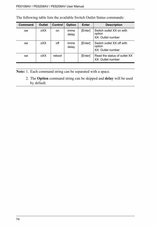
PE6108AV / PE6208AV / PE8208AV User Manual
74
The following table lists the available Switch Outlet Status commands:
Note: 1. Each command string can be separated with a space.
2. The Option command string can be skipped and delay will be used by default.
Command Outlet Control Option Enter Description
sw oXX on immedelay
[Enter] Switch outlet XX on with optionXX: Outlet number
sw oXX off immedelay
[Enter] Switch outlet XX off with option XX: Outlet number
sw oXX reboot [Enter] Read the status of outlet XXXX: Outlet number

Chapter 5. RS-232 / Telnet Commands
75
Read Power ValueThe Read Power Value command allows you to view the power measurement values of the eco PDU, Bank or Outlet.
The formula for Read Power Value commands is as follows:Command + Target + Number + Measurement + Return String + [Enter]
1. For example, if you want to read the voltage measurement of outlet 12 with a simple return string, type the following:read meter olt o12 volt simple [Enter]
2. For example, if you want to read the power dissipation measurement of bank 02 with a format return string, type the following:read meter bnk o02 pd format [Enter]
3. For example, if you want to read the voltage frequency measurement of the PDU with a simple return string, type the following:read meter dev freq simple [Enter]
The following tables show the possible values for the Read Power Value commands:
Command Description
read meter Read power value command
Target Description
dev Get value from PDU
bnk Get value from bank
olt Get value from outlet
Number Description
o Target number command
xx Bank or outlet numberxx: Bank or Outlet on PDUExample: o02
Measurement Description
curr Read current measurement
volt Read voltage measurement
pow Read power measurement
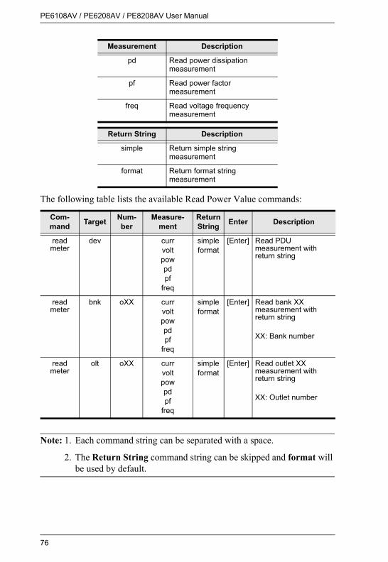
PE6108AV / PE6208AV / PE8208AV User Manual
76
The following table lists the available Read Power Value commands:
Note: 1. Each command string can be separated with a space.
2. The Return String command string can be skipped and format will be used by default.
pd Read power dissipation measurement
pf Read power factor measurement
freq Read voltage frequency measurement
Return String Description
simple Return simple string measurement
format Return format string measurement
Com-mand Target Num-
berMeasure-
mentReturn String Enter Description
read meter
dev currvoltpowpdpf
freq
simpleformat
[Enter] Read PDU measurement with return string
read meter
bnk oXX currvoltpowpdpf
freq
simpleformat
[Enter] Read bank XX measurement with return string
XX: Bank number
read meter
olt oXX currvoltpowpdpf
freq
simpleformat
[Enter] Read outlet XX measurement with return string
XX: Outlet number
Measurement Description

Chapter 5. RS-232 / Telnet Commands
77
Read Environmental ValueThe Read Environmental Value command allows you to view measurements from the eco PDU’s environmental sensors.
The formula for Read Environmental Value commands is as follows:Command + Sensor + Number + Return String + [Enter]
1. For example, if you want to read environmental sensor 02 with a simple return string, type the following:read sensor o02 simple [Enter]
2. For example, if you want to read environmental sensor 01 with a format return sting, type the following:read sensor o01 format [Enter]
The following tables show the possible values for the Read Environmental Value commands:
The following table lists the available Read Environmental Value commands:
Command Description
read sensor Read environmental value command
Sensor Description
o Environmental sensor command
xx Sensor numberxx: Environmental sensor on PDU (01~04)Example: o02
Return String Description
simple Return simple string measurement
format Return format string measurement
Command Sensor Return String Enter Description
read sensor oXX simpleformat
[Enter] Read environmental sensor XX with return string option
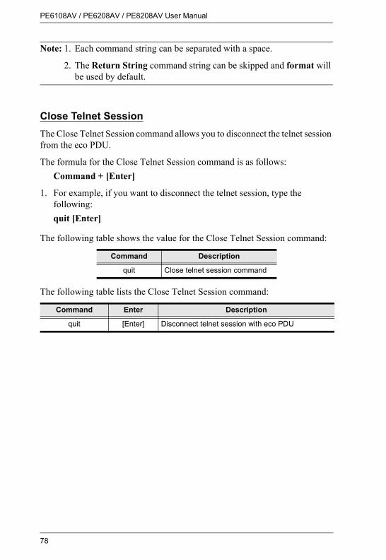
PE6108AV / PE6208AV / PE8208AV User Manual
78
Note: 1. Each command string can be separated with a space.
2. The Return String command string can be skipped and format will be used by default.
Close Telnet SessionThe Close Telnet Session command allows you to disconnect the telnet session from the eco PDU.
The formula for the Close Telnet Session command is as follows:Command + [Enter]
1. For example, if you want to disconnect the telnet session, type the following:quit [Enter]
The following table shows the value for the Close Telnet Session command:
The following table lists the Close Telnet Session command:
Command Description
quit Close telnet session command
Command Enter Description
quit [Enter] Disconnect telnet session with eco PDU

79
Appendix
Safety Instructions
GeneralThis product is for indoor use only.Read all of these instructions. Save them for future reference.Follow all warnings and instructions marked on the device.Do not place the device on any unstable surface (cart, stand, table, etc.). If the device falls, serious damage will result.Do not use the device near water.Do not place the device near, or over, radiators or heat registers.The device cabinet is provided with slots and openings to allow for adequate ventilation. To ensure reliable operation, and to protect against overheating, these openings must never be blocked or covered.The device should never be placed on a soft surface (bed, sofa, rug, etc.) as this will block its ventilation openings. Likewise, the device should not be placed in a built in enclosure unless adequate ventilation has been provided.Never spill liquid of any kind on the device.Avoid circuit overloads. Before connecting equipment to a circuit, know the power supply’s limit and never exceed it. Always review the electrical specifications of a circuit to ensure that you are not creating a dangerous condition or that one doesn’t already exist. Circuit overloads can cause a fire and destroy equipment. Unplug the device from the wall outlet before cleaning. Do not use liquid or aerosol cleaners. Use a damp cloth for cleaning.The device should be operated from the type of power source indicated on the marking label. If you are not sure of the type of power available, consult your dealer or local power company.To prevent damage to your installation it is important that all devices are properly grounded.The device is equipped with a 3-wire grounding type plug. This is a safety feature. If you are unable to insert the plug into the outlet, contact your electrician to replace your obsolete outlet. Do not attempt to defeat the

PE6108AV / PE6208AV / PE8208AV User Manual
80
purpose of the grounding-type plug. Always follow your local/national wiring codes.The equipment should be installed near the wall socket outlet and the disconnect device (appliance coupler) should be readily accessible.Do not allow anything to rest on the power cord or cables. Route the power cord and cables so that they cannot be stepped on or tripped over.To help protect your system from sudden, transient increases and decreases in electrical power, use a surge suppressor, line conditioner, or uninterruptible power supply (UPS).Position system cables and power cables carefully; Be sure that nothing rests on any cables.When connecting or disconnecting power to hot pluggable power supplies, observe the following guidelines:
Install the power supply before connecting the power cable to the power supply.Unplug the power cable before removing the power supply.If the system has multiple sources of power, disconnect power from the system by unplugging all power cables from the power supplies.
Never push objects of any kind into or through cabinet slots. They may touch dangerous voltage points or short out parts resulting in a risk of fire or electrical shock.Do not attempt to service the device yourself. Refer all servicing to qualified service personnel.If the following conditions occur, unplug the device from the wall outlet and bring it to qualified service personnel for repair.
The power cord or plug has become damaged or frayed.Liquid has been spilled into the device.The device has been exposed to rain or water.The device has been dropped, or the cabinet has been damaged.The device exhibits a distinct change in performance, indicating a need for service.The device does not operate normally when the operating instructions are followed.
Only adjust those controls that are covered in the operating instructions. Improper adjustment of other controls may result in damage that will require extensive work by a qualified technician to repair.

Appendix
81
Do not connect the RJ-11 connector marked “Sensor” to a public telecommunication network.

PE6108AV / PE6208AV / PE8208AV User Manual
82
Consignes de sécurité
GénéralCe produit est destiné exclusivement à une utilisation à l’intérieur.Veuillez lire la totalité de ces instructions. Conservez-les afin de pouvoir vous y référer ultérieurement.Respectez l’ensemble des avertissements et instructions inscrits sur l’appareil.Ne placez jamais l’unité sur une surface instable (chariot, pied, table, etc.). Si l’unité venait à tomber, elle serait gravement endommagée.N’utilisez pas l’unité à proximité de l’eau.Ne placez pas l’unité à proximité de ou sur des radiateurs ou bouches de chaleur.Le boîtier de l’unité est doté de fentes et d’ouvertures destinées à assurer une ventilation adéquate. Pour garantir un fonctionnement fiable et protéger l’unité contre les surchauffes, ces ouvertures ne doivent jamais être bloquées ou couvertes.L’unité ne doit jamais être placée sur une surface molle (lit, canapé, tapis, etc.) car ses ouvertures de ventilation se trouveraient bloquées. De même, l’unité ne doit pas être placée dans un meuble fermé à moins qu'une ventilation adaptée ne soit assurée.Ne renversez jamais de liquides de quelque sorte que ce soit sur l’unité.Evitez toute surcharge du circuit. Avant de connecter l’equipement a un circuit, verifiez la limite de l’alimentation et ne la depassez pas. Controlez toujours les caracteristiques electriques d'un circuit pour vous assurer de ne pas creer de situation dangereuse ou qu’il n’y en a pas deja. Les surcharges du circuit peuvent provoquer un incendie et detruire l’equipement.Débranchez l’unité de la prise murale avant de la nettoyer. N’utilisez pas de produits de nettoyage liquide ou sous forme d’aérosol. Utilisez un chiffon humide pour le nettoyage de l’unité.L’appareil doit être alimenté par le type de source indiqué sur l’étiquette. Si vous n’êtes pas sûr du type d’alimentation disponible, consultez votre revendeur ou le fournisseur local d’électricité.Afin de ne pas endommager votre installation, vérifiez que tous les périphériques sont correctement mis à la terre.

Appendix
83
L’unité est équipée d’une fiche de terre à trois fils. Il s’agit d’une fonction de sécurité. Si vous ne parvenez pas à insérer la fiche dans la prise murale, contactez votre électricité afin qu’il remplace cette dernière qui doit être obsolète. N’essayez pas d’aller à l’encontre de l’objectif de la fiche de terre. Respectez toujours les codes de câblage en vigueur dans votre région/pays.L’équipement doit être installé à proximité de la prise murale et le dispositif de déconnexion (prise de courant femelle) doit être facile d’accès.Veillez à ce que rien ne repose sur le cordon d’alimentation ou les câbles. Acheminez le cordon d’alimentation et les câbles de sorte que personne ne puisse marcher ou trébucher dessus.Pour contribuer à protéger votre système contre les augmentations et diminutions soudaines et transitoires de puissance électrique, utilisez un parasurtenseur, un filtre de ligne ou un système d’alimentation sans coupure (UPS).Placez les câbles du système et les câbles d’alimentation avec précaution; veillez à ce que rien ne repose sur aucun des câbles.Lors du branchement ou du débranchement à des blocs d’alimentation permettant la connexion à chaud, veuillez respecter les lignes directrices suivantes:
Installez le bloc d’alimentation avant de brancher le câble d’alimentation à celui-ci.Débranchez le câble d’alimentation avant de retirer le bloc d'alimentation.Si le système présente plusieurs sources d’alimentation, déconnectez le système de l'alimentation en débranchant tous les câbles d'alimentation des blocs d'alimentation.
N’insérez jamais d’objets de quelque sorte que ce soit dans ou à travers les fentes du boîtier. Ils pourraient entrer en contact avec des points de tension dangereuse ou court-circuiter des pièces, entraînant ainsi un risque d’incendie ou de choc électrique.N’essayez pas de réparer l’unité vous-même. Confiez toute opération de réparation à du personnel qualifié.Si les conditions suivantes se produisent, débranchez l’unité de la prise murale et amenez-la à un technicien qualifié pour la faire réparer.
Le cordon d’alimentation ou la fiche ont été endommagés ou éraillés.Du liquide a été renversé dans l’unité.

PE6108AV / PE6208AV / PE8208AV User Manual
84
L’unité a été exposée à la pluie ou à l’eau.L’unité est tombée ou le boîtier a été endommagé.Les performances de l’unité sont visiblement altérées, ce qui indique la nécessité d’une réparation.L’unité ne fonctionne pas normalement bien que les instructions d’utilisation soient respectées.
N’utilisez que les commandes qui sont abordées dans le mode d’emploi. Le réglage incorrect d’autres commandes peut être à l’origine de dommages qui nécessiteront beaucoup de travail pour qu’un technicien qualifié puisse réparer l’unité.Ne connectez pas le connecteur RJ-11 portant la marque « Sensor » (Capteur) à un réseau de télécommunication public.

Appendix
85
Rack MountingBefore working on the rack, make sure that the stabilizers are secured to the rack, extended to the floor, and that the full weight of the rack rests on the floor. Install front and side stabilizers on a single rack or front stabilizers for joined multiple racks before working on the rack.Always load the rack from the bottom up, and load the heaviest item in the rack first.Make sure that the rack is level and stable before extending a device from the rack.Use caution when pressing the device rail release latches and sliding a device into or out of a rack; the slide rails can pinch your fingers.After a device is inserted into the rack, carefully extend the rail into a locking position, and then slide the device into the rack.Do not overload the AC supply branch circuit that provides power to the rack. The total rack load should not exceed 80 percent of the branch circuit rating.Make sure that all equipment used on the rack – including power strips and other electrical connectors – is properly grounded.Ensure that proper airflow is provided to devices in the rack.Ensure that the operating ambient temperature of the rack environment does not exceed the maximum ambient temperature specified for the equipment by the manufacturerDo not step on or stand on any device when servicing other devices in a rack.
The eco PDU’s Main Power CordUse the power cord supplied with this package. If it becomes necessary to replace the cord supplied with this package, be sure to use a cord of at least the same standard as the one provided.
Securing the Power CablesTo secure the cables in the eco PDU’s power outlets, use only the ATEN Lok-U-Plug cable holders that have been specifically designed to work with the eco PDU. Using any other kind of cable securing device could be highly dangerous. Please contact your ATEN dealer
for information about ATEN Lok-U-Plugs.

PE6108AV / PE6208AV / PE8208AV User Manual
86
Montage sur bâtiAvant de travailler sur le bâti, assurez-vous que les stabilisateurs sont bien fixées sur le bâti, qu’ils sont étendus au sol et que tout le poids du bâti repose sur le sol. Installez les stabilisateurs avant et latéraux sur un même bâti ou bien les stabilisateurs avant si plusieurs bâtis sont réunis, avant de travailler sur le bâti.Chargez toujours le bâti de bas en haut et chargez l’élément le plus lourd en premier.Assurez-vous que le bâti est à niveau et qu’il est stable avant de sortir une unité du bâti.Agissez avec précaution lorsque vous appuyez sur les loquets de libération du rail d’unité et lorsque vous faites coulisser une unité dans et hors d’un bâti ; vous pourriez vous pincer les doigts dans les rails.Une fois qu’une unité a été insérée dans le bâti, étendez avec précaution le rail dans une position de verrouillage puis faites glisser l’unité dans le bâti.Ne surchargez pas le circuit de l’alimentation CA qui alimente le bâti. La charge totale du bâti ne doit pas dépasser 80 % de la capacité du circuit.Assurez-vous que tous les équipements utilisés sur le bâti, y-compris les multiprises et autres connecteurs électriques, sont correctement mis à la terre.Assurez-vous que les unités présentes dans le bâti bénéficie d’une circulation d’air suffisante.Assurez-vous que la température ambiante de fonctionnement de l’environnement du bâti ne dépasse pas la température ambiante maximale spécifiée pour l’équipement par le fabricant.Ne marchez sur aucun appareil lors de la maintenance d’autres appareils d’un bâti.
Le cordon d’alimentation principale de l’unité d’alimentation écoUtilisez le câble d’alimentation fourni. Au cas où il s’avèrerait nécessaire de remplacer le cordon fourni avec l’appareil, veillez à utiliser un cordon respectant au minimum la même norme que celui d’origine.
Fixation des câbles d’alimentationPour fixer les câbles aux sorties d’alimentation de l’unité d’alimentation éco, utilisez uniquement les supports de câble Lok-U-Plug d’ATEN qui ont été conçus spécialement pour être utilisés

Appendix
87
avec l’unité d’alimentation éco. L’utilisation de tout autre type système de fixation de câble pourrait s’avérer très dangereuse. Veuillez contacter votre revendeur ATEN pour plus d’informations sur le support de câble ATEN Lok-U-Plug.

PE6108AV / PE6208AV / PE8208AV User Manual
88
Technical SupportInternational
For online technical support – including troubleshooting, documentation, and software updates: http://eservice.aten.comFor telephone support, see Telephone Support, page iii
North America
When you contact us, please have the following information ready beforehand:Product model number, serial number, and date of purchase.Your computer configuration, including operating system, revision level, expansion cards, and software.Any error messages displayed at the time the error occurred.The sequence of operations that led up to the error.Any other information you feel may be of help.
Email Support [email protected]
Online Technical Support
TroubleshootingDocumentationSoftware Updates
http://eservice.aten.com
Telephone Support 1-888-999-ATEN ext 49881-949-428-1111

Appendix
89
IP Address Determination
If you are an administrator logging in for the first time, you need to access the eco PDU in order to give it an IP address that users can connect to. There are two methods to choose from. In each case, your client computer must be on the same network segment as the eco PDU. After you have connected and logged in you can give the device its fixed network address. (See Notification Settings, page 46.)
Method 1:For computers running Windows, an IP address can be determined and/or assigned with the IP Installer utility. The utility can be obtained from the Download area of our web site or from the software CD. Look under Driver/SW, and the model of your device. After downloading the utility to your computer, do the following:
1. Unzip the contents of IPInstaller.zip to a directory on your hard drive.
2. Go to the directory that you unzipped the IPInstaller program to and run IPInstaller.exe. A dialog box similar to the one below appears:
(Continues on next page.)

PE6108AV / PE6208AV / PE8208AV User Manual
90
(Continued from previous page.)
3. Select the device in the Device List.
Note: 1. If the list is empty, or your device doesn't appear, click Enumerate to refresh the Device List.
2. If there is more than one device in the list, use the MAC address to pick the one you want. The eco PDU's MAC address is located on its bottom panel.
4. Select either Obtain an IP address automatically (DHCP), or Specify an IP address. If you chose the latter, fill the IP Address, Subnet Mask, and Gateway fields with the information appropriate to your network.
5. Click Set IP.
6. After the IP address shows up in the Device List, click Exit to end the program.
Method 2:
1. Set your computer's IP address to 192.168.0.XXXWhere XXX represents any number or numbers except 60. (192.168.0.60) is the default address of the eco PDU.)
2. Specify the device’s default IP address (192.168.0.60) in your browser, and you will be able to connect.
3. Assign a fixed IP address for the device (see IPv4 Configuration, page 49), that is suitable for the network segment that it resides on.
4. After you log out, reset your computer's IP address to its original value.
5. Once you have logged in, go to Network Settings to set up the permanent IP environment (see IPv4 Configuration, page 49).
Method 3:NRGence eco Sensors allows you to determine/assign an IP address in order to configure a PDU device and monitor power status of the equipment connected to it. NRGence eco Sensors can be obtained from the Download area of the ATEN web site.
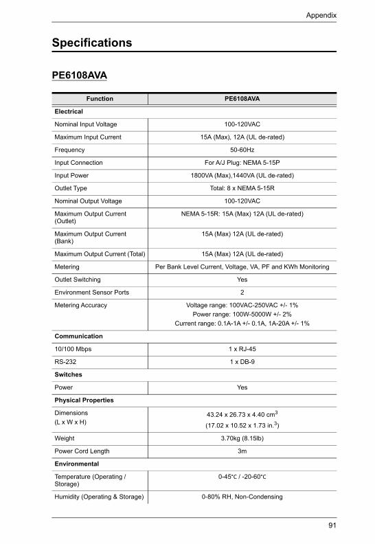
Appendix
91
Specifications
PE6108AVA
Function PE6108AVA
Electrical
Nominal Input Voltage 100-120VAC
Maximum Input Current 15A (Max), 12A (UL de-rated)
Frequency 50-60Hz
Input Connection For A/J Plug: NEMA 5-15P
Input Power 1800VA (Max),1440VA (UL de-rated)
Outlet Type Total: 8 x NEMA 5-15R
Nominal Output Voltage 100-120VAC
Maximum Output Current (Outlet)
NEMA 5-15R: 15A (Max) 12A (UL de-rated)
Maximum Output Current (Bank)
15A (Max) 12A (UL de-rated)
Maximum Output Current (Total) 15A (Max) 12A (UL de-rated)
Metering Per Bank Level Current, Voltage, VA, PF and KWh Monitoring
Outlet Switching Yes
Environment Sensor Ports 2
Metering Accuracy Voltage range: 100VAC-250VAC +/- 1%Power range: 100W-5000W +/- 2%
Current range: 0.1A-1A +/- 0.1A, 1A-20A +/- 1%
Communication
10/100 Mbps 1 x RJ-45
RS-232 1 x DB-9
Switches
Power Yes
Physical Properties
Dimensions(L x W x H)
43.24 x 26.73 x 4.40 cm3
(17.02 x 10.52 x 1.73 in.3)
Weight 3.70kg (8.15lb)
Power Cord Length 3m
Environmental
Temperature (Operating / Storage)
0-45°C / -20-60°C
Humidity (Operating & Storage) 0-80% RH, Non-Condensing

PE6108AV / PE6208AV / PE8208AV User Manual
92
Compliance
EMC Verification FCC, J55032
Safety Verification PSE
Function PE6108AVA

Appendix
93
PE6208AVA / PE6208AVB / PE6208AVG / PE6208AVX
Function PE6208AVA PE6208AVB PE6208AVG PE6208AVX
Electrical
Nominal Input Voltage
100-120VAC 100-240VAC 100-240VAC 100-240VAC
Maximum Input Current
20A (Max), 16A (UL de-rated)
20A (Max), 16A (UL de-rated)
16A (Max) 16A
Frequency 50-60Hz
Input Connection A/J:NEMA L5-20P A2/J2: NEMA
5-20P
NEMA 6-20P IEC 60320 C20 Terminal Block (3P)
Input Power 2400VA (Max), 1920VA (UL de-
rated)
4600VA (Max), 3680VA (UL de-
rated)
3680 VA (Max) 4800VA (Max)
Outlet Type Total: 8 x NEMA 5-20R
Total: 8 x IEC320 C13
Total: 8 x IEC320 C13
Total: 8 x Terminal Block (3P)
Nominal Output Voltage
100-120VAC 100-240VAC 100-240VAC 100-240VAC
Maximum Output Current (Outlet)
NEMA 5-20R: 20A (Max) 16A (UL de-rated)
C13: 15A (Max) 12A (UL de-rated)
C13: 10A 16A (Max)
Maximum Output Current (Bank)
20A (Max) 16A (UL de-rated)
20A (Max) 16A (UL de-rated)
16A (Max) 16A (Max)
Maximum Output Current (Total)
20A (Max) 16A (UL de-rated)
20A (Max) 16A (UL de-rated)
16A (Max) 16A (Max)
Metering Per Bank Level Current, Voltage, VA, PF and KWh Monitoring
Outlet Switching Yes
Environment Sensor Ports
2
Metering Accuracy
Voltage range: 100VAC-250VAC +/- 1%Power range: 100W-5000W +/- 2%
Current range: 0.1A-1A +/- 0.1A, 1A-20A +/- 1%
Communication
10/100 Mbps 1 x RJ-45
RS-232 1 x DB-9
Switches
Power Yes
Physical Properties
Dimensions(L x W x H)
43.24 x 26.72 x 4.40 cm3
(17.02 x 10.52 x 1.73 in.3)
Weight 3.76kg (8.28lb)

PE6108AV / PE6208AV / PE8208AV User Manual
94
Power Cord Length
3m 3m 3m N.A.
Environmental
Temperature (Operating / Storage)
0-50°C / -20-60°C 0-50°C / -20-60°C 0-40°C / -20-60°C 0-50°C / -20-60°C
Humidity (Operating & Storage)
0-80% RH, Non-Condensing
Compliance
EMC Verification FCC, J55032 FCC Others by Request
CE-EMC, FCC, J55032 Others by
Request
FCC, CE
Safety Verification PSE Others by Request
CE-LVD, Others by Request
CE, LVD
Function PE6208AVA PE6208AVB PE6208AVG PE6208AVX
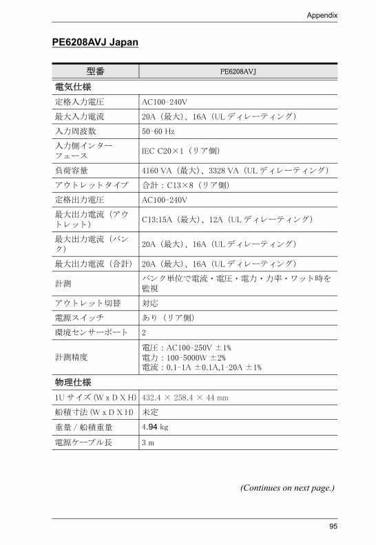
Appendix
95
PE6208AVJ Japan
型番 PE6208AVJ
電気仕様
定格入力電圧 AC100–240V
大入力電流 20A ( 大)、 16A (UL デ ィ レーテ ィ ング)
入力周波数 50–60 Hz
入力側イ ン ターフ ェース
IEC C20×1 ( リ ア側)
負荷容量 4160 VA ( 大)、 3328 VA (UL デ ィ レーテ ィ ング)
ア ウ ト レ ッ ト タ イプ 合計 : C13×8 ( リ ア側)
定格出力電圧 AC100–240V
大出力電流 (ア ウト レ ッ ト )
C13:15A ( 大)、 12A (UL デ ィ レーテ ィ ング)
大出力電流 (バンク)
20A ( 大)、 16A (UL デ ィ レーテ ィ ング)
大出力電流 (合計) 20A ( 大)、 16A (UL デ ィ レーテ ィ ング)
計測バン ク単位で電流 ・ 電圧 ・ 電力 ・ 力率 ・ ワ ッ ト 時を監視
ア ウ ト レ ッ ト 切替 対応
電源ス イ ッチ あ り ( リ ア側)
環境センサーポー ト 2
計測精度電圧 : AC100–250V ±1%電力 : 100–5000W ±2%電流 : 0.1–1A ±0.1A,1–20A ±1%
物理仕様
1U サイ ズ (W x D X H) 432.4 × 258.4 × 44 mm
船積寸法 (W x D X H) 未定
重量 / 船積重量 4.94 kg
電源ケーブル長 3 m
(Continues on next page.)

PE6108AV / PE6208AV / PE8208AV User Manual
96
コネ ク ター
LAN RJ-45×1 ( リ ア側)
センサーポー ト RJ-11×2 ( リ ア側、 49 cm カテゴ リ 5 ケーブル)
RS-232 DB-9×1 ( リ ア側)
ボタ ン
リ セ ッ トピンホール型ス イ ッチ ×1 (フ ロ ン ト 側)ピンホール型ス イ ッチ ×1 ( リ ア側)
選択 プ ッ シ ュボタ ン ×1 (フ ロ ン ト 側)
リ モー ト ON/OFF&電源 ON/OFF
プ ッ シ ュボタ ン ×8 (フ ロ ン ト 側)
LED
電流 /IP 7 セグ メ ン ト デジ タル表示 ×2 (フ ロ ン ト 側)
10/100 Mbps オレンジ / グ リ ーン ×1 (フ ロ ン ト 側)
リ モー ト ア ク セス グ リ ーン ×8 (フ ロ ン ト 側)
オン ラ イ ン オレンジ ×8 (フ ロ ン ト 側)
電流 レ ッ ド ×1 (フ ロ ン ト 側)
リ ン ク グ リ ーン ×1 (フ ロ ン ト 側)
センサー グ リ ーン ×2 ( リ ア側)
電源 ブルー ×1 (フ ロ ン ト 側)
動作環境
温度 (動作 / 保管) 0–50 oC / -20–60 oC
湿度 (動作&保管) 0–80% RH, 結露なき こ と
規格準拠
EMC 認証 J55022
安全性検証 PSE
型番 PE6208AVJ

Appendix
97
PE8208AVB / PE8208AVG
Function PE8208AVB PE8208AVGPower Outlets Direct 8
Connectors Power Inlet 1 x IEC 320 C20
Power Outlets 8 x IEC 320 C13
Sensor 2 x RJ-11
LAN 1 x RJ-45 (F)
RS-232 1 x DB-9 (M)
LEDs Current / IP 2-digit 7-segment (Yellow)
Outlet Power 8 (Orange)
Local 8 (Green)
Current 1 (Red)
Link 1 (Green)
Sensor 2 (Green)
Power 1 (Blue)
LAN 10/100M 1 (Orange / Green)
Switches Reset 2 x Semi-recessed Pushbutton
Power 1 x Rocker
Remote/OutletON/Off
8 x Pushbutton
Current / IP 1 x Pushbutton
I/P Rating 100–240V~; 50-60Hz; 20A (Max); 16A (UL de-rated)
100–240V~; 50-60Hz; 16A
Load Capacity 4160 VA (Max) 3680 VA (Max)
O/P Rating Per Port 100–240V~; 50-60Hz; 15A (Max); 12A (UL de-rated)
100–240V~; 50-60Hz; 10A (Max)
Per Bank 100–240V~; 50-60Hz; 20A (Max); 16A (UL de-rated)
100–240V~; 50-60Hz; 16A (Max)
Total 100–240V~; 50-60Hz; 20A (Max); 16A (UL de-rated)
100–240V~; 50-60Hz; 16A (Max)
Environment Operating Temperature 0–50oC
Storage Temperature -20–60oC
Humidity 0–80% RH Non-condensing
Physical Properties
Housing Metal
Weight TBD TBD
Dimensions (L x W x H) 43.24 x 4.40 x 25.84 cm

PE6108AV / PE6208AV / PE8208AV User Manual
98
PE8208AVJ Japan
型番 PE8208AVJ
電気仕様
定格入力電圧 AC100–240V
大入力電流 20A ( 大)、 16A (UL デ ィ レーテ ィ ング)
入力周波数 50–60 Hz
入力側イ ン ターフ ェース
IEC C20×1 ( リ ア側)
負荷容量 4160 VA ( 大)、 3328 VA (UL デ ィ レーテ ィ ング)
アウ ト レ ッ ト タ イプ 合計 : C13×8 ( リ ア側)
定格出力電圧 AC100–240V
大出力電流 (アウト レ ッ ト )
C13:15A ( 大)、 12A (UL デ ィ レーテ ィ ング)
大出力電流 (バンク)
20A ( 大)、 16A (UL デ ィ レーテ ィ ング)
大出力電流 (合計) 20A ( 大)、 16A (UL デ ィ レーテ ィ ング)
計測ア ウ ト レ ッ ト 単位で電流 ・ 電圧 ・ 電力 ・ 力率 ・ ワ ット 時を監視
アウ ト レ ッ ト 切替 対応
電源ス イ ッチ あ り ( リ ア側)
環境センサーポー ト 2
計測精度電圧 : AC100–250V ±1%電力 : 100–5000W ±2%電流 : 0.1–1A ±0.1A, 1–20A ±1%
物理仕様
1U サイ ズ (W x D x H) 432.4 x 258.4 x 44 mm
船積寸法 (W x D x H) 未定
重量 / 船積重量 未定
電源ケーブル長 3 m
(Continues on next page.)

Appendix
99
コネ ク ター
LAN RJ-45×1 ( リ ア側)
センサーポー ト RJ-11×2 ( リ ア側、 49 cm カテゴ リ 5 ケーブル)
RS-232 DB-9×1 ( リ ア側)
ボタ ン
リ セ ッ トピンホール型ス イ ッチ ×1 (フ ロ ン ト 側)ピンホール型ス イ ッチ ×1 ( リ ア側)
選択 プ ッ シュボタ ン ×1 (フ ロ ン ト 側)
リ モー ト ON/OFF&電源 ON/OFF
プ ッ シュボタ ン ×8 (フ ロ ン ト 側)
LED
電流 /IP 7 セグ メ ン ト デジ タル表示 ×2 (フ ロ ン ト 側)
10/100 Mbps オレ ンジ / グ リ ーン ×1 (フ ロ ン ト 側)
リ モー ト ア ク セス グ リ ーン ×8 (フ ロ ン ト 側)
オン ラ イ ン オレ ンジ ×8 (フ ロ ン ト 側)
電流 レ ッ ド ×1 (フ ロ ン ト 側)
リ ン ク グ リ ーン ×1 (フ ロ ン ト 側)
センサー グ リ ーン ×2 ( リ ア側)
電源 ブルー ×1 (フ ロ ン ト 側)
動作環境
温度 (動作 / 保管) 0–50 oC / -20–60 oC
湿度 (動作&保管) 0–80% RH、 結露なき こ と
規格準拠
EMC 認証 J55022
安全性検証 PSE
型番 PE8208AVJ

PE6108AV / PE6208AV / PE8208AV User Manual
100
Administrator Login Failure
If you are unable to perform an Administrator login (because the Username and Password information has become corrupted, or you have forgotten it, for example), you can clear the login information with the following procedure:
1. Power off the eco PDU and remove its housing.
2. Short the jumper labeled J4 (PIN1 and PIN2).
3. Power on the eco PDU.
4. When the 2-digit, 7-segment display shows “00”, power off the switch.
5. Remove the jumper cap from J4.
6. Close the housing and start the eco PDU.After you start, you can use the default Username and Password to log in.
J4

Appendix
101
Limited Warranty
ATEN warrants its hardware in the country of purchase against flaws in materials and workmanship for a Warranty Period of two [2] years (warranty period may vary in certain regions/countries) commencing on the date of original purchase. This warranty period includes the LCD panel of ATEN LCD KVM switches. Select products are warranted for an additional year (see A+ Warranty for further details). Cables and accessories are not covered by the Standard Warranty.
What is covered by the Limited Hardware WarrantyATEN will provide a repair service, without charge, during the Warranty Period. If a product is detective, ATEN will, at its discretion, have the option to (1) repair said product with new or repaired components, or (2) replace the entire product with an identical product or with a similar product which fulfills the same function as the defective product. Replaced products assume the warranty of the original product for the remaining period or a period of 90 days, whichever is longer. When the products or components are replaced, the replacing articles shall become customer property and the replaced articles shall become the property of ATEN.
To learn more about our warranty policies, please visit our website:http://www.aten.com/global/en/legal/policies/warranty-policy/

PE6108AV / PE6208AV / PE8208AV User Manual
102