peace river site c hydro project highway 29 relocations
TRANSCRIPT

Report No. P05032A02-11-003 July 2009
Not to be reproduced without the permission of BC Hydro
PEACE RIVER
SITE C HYDRO PROJECT
HIGHWAY 29 RELOCATIONS
Prepared by
Klohn Crippen Berger Ltd. and SNC-Lavalin Inc.
For
BC Hydro

Report No. P05032A02-11-003 July 2009
Not to be reproduced without the permission of BC Hydro
PEACE RIVER SITE C HYDRO PROJECT
HIGHWAY 29 RELOCATIONS
Prepared by
Klohn Crippen Berger Ltd. and SNC-Lavalin Inc.
For
B.C. Hydro


Peace River – Site C Hydro Project Highway 29 Relocations Page iv
Report No. P05032A02-11-003 July 2009
Not to be reproduced without the permission of BC Hydro
EXECUTIVE SUMMARY
Filling the potential Site C reservoir would flood parts of the existing provincial Highway 29 between Hudson’s Hope and Fort St John. Studies to identify and investigate realignment options for the relocation of the affected segments of Highway 29 were first undertaken and documented in 1982 by other consultants. During Stage 2, Klohn Crippen Berger Ltd. (KCBL) and SNC-Lavalin Inc (SLI), together with Urban Systems (US), updated those studies. The historically identified realignment options for each relocated segment of highway were updated to current Ministry of Transportation and Infrastructure (MoT) design standards. In addition, a number of alternative feasibility level designs and layouts were developed for the river crossings that would be affected by the realignments. The current study did not include land-use studies, heritage resources, archaeological studies, environmental assessment, or any realignments required to mitigate any impacts. This report presents the results of the updated Highway 29 realignment options and river crossing designs developed during Stage 2, including the design standards and design criteria that have been adopted.

Peace River – Site C Hydro Project Highway 29 Relocations Page v
Report No. P05032A02-11-003 July 2009
Not to be reproduced without the permission of BC Hydro
TABLE OF CONTENTS
Page
EXECUTIVE SUMMARY..................................................................................... IV
1 INTRODUCTION ....................................................................................... 1
2 DESIGN CRITERIA ................................................................................... 2
2.1 General: .......................................................................................... 2
2.2 Design Loads: ................................................................................. 2
2.3 Materials: ........................................................................................ 3
2.4 Drainage: ........................................................................................ 4
2.5 Environmental: ................................................................................ 4
3 CONCEPTUAL DESIGN ALTERNATIVES................................................ 5
3.1 The Lynx Creek Crossing................................................................ 6
3.1.1 Lynx Creek Crossing Alternative 1 ....................................... 7
3.1.2 Lynx Creek Crossing Alternative 2 ....................................... 8
3.2 The Farrell Creek Crossing ............................................................. 9
3.2.1 Farrell Creek Crossing Alternative 1................................... 10
3.2.2 Farrell Creek Crossing Alternative 2................................... 11
3.3 The Halfway River Crossing.......................................................... 11
3.3.1 Halfway River Crossing Alternative 1 ................................. 12
3.3.2 Halfway River Crossing Alternative 2 ................................. 13
3.4 The Cache Creek Crossing........................................................... 14
3.4.1 Cache Creek Crossing Alternative 1 .................................. 14
3.4.2 Cache Creek Crossing Alternative 2 .................................. 15
3.4.3 Cache Creek Crossing Alternative 3 .................................. 16
4 CONCEPTUAL DRAWINGS.................................................................... 18
5 DISCUSSION .......................................................................................... 19
5.1 The Lynx Creek Crossing.............................................................. 19
5.2 The Farrell Creek Crossing ........................................................... 19
5.3 The Halfway River Crossing.......................................................... 20
5.4 The Cache Creek Crossing........................................................... 20
6 REFERENCES ........................................................................................ 21

Peace River – Site C Hydro Project Highway 29 Relocations Page vi
Report No. P05032A02-11-003 July 2009
Not to be reproduced without the permission of BC Hydro
APPENDICES
Appendix I Conceptual Drawings
Appendix II Highway 29 Relocation, Hudson Hope to Charlie Lake – Urban Systems Report

Peace River – Site C Hydro Project Highway 29 Relocations Page i
Report No. P05032A02-11-003 July 2009
Not to be reproduced without the permission of BC Hydro
DISCLAIMER
This report was prepared by Klohn Crippen Berger and SNC-Lavalin solely for BC Hydro internal purposes. All other parties are third parties. Neither BC Hydro nor Klohn Crippen Berger nor SNC-Lavalin represents, guarantees or warrants to any third party, either expressly or by implication:
(a) the accuracy, completeness or usefulness of; (b) the intellectual or other property rights of any person or party in, or
(c) the merchantability, safety or fitness for purpose of,
any information, product or process disclosed, described or recommended in this report. Neither BC Hydro nor Klohn Crippen Berger nor SNC-Lavalin accept any liability of any kind arising in any way out of the use by a third party of any information, product or process disclosed, described or recommended in this report, nor do BC Hydro, Klohn Crippen Berger or SNC-Lavalin accept any liability arising by way of reliance by a third party upon any information, statement or recommendation contained in this report. Should third parties use or rely on any information, product or process disclosed, described or recommended in this report, they do so entirely at their own risk.
COPYRIGHT NOTICE
© 2009 BC Hydro. This report may not be reproduced in whole or in part without the prior written consent of BC Hydro.

Peace River – Site C Hydro Project Highway 29 Relocations Page 1
Report No. P05032A02-11-003 July 2009
Not to be reproduced without the permission of BC Hydro
1 INTRODUCTION
The reservoir for the proposed “Site C” hydroelectric project would inundate parts of Highway 29 between Hudson Hope and Fort St. John. In addition to local highway realignment, the following four (4) Ministry of Transportation and Infrastructure bridges would need to be replaced:
Lynx Creek Bridge No. 2327
Farrell Creek Bridge No. 2184
Halfway River Bridge No. 1042
Cache Creek Bridge No. 1025
This report summarizes the conceptual design for each of the four replacement structures and the functional design of various realignment options undertaken during Stage 2 for the four segments of Highway 29 that would be flooded. Design criteria for the four replacement structures and the highway realignments are identified within the report. Conceptual drawings of the highway relocation options and the river crossing alternatives are provided in Appendix I. Details of the highway realignments are provided in Appendix II.
The conceptual drawings show the rights-of-way for the various realignment options and span configurations for the replacement structure alternatives. This report also provides a comparison of the structure alternatives considered for each of the crossings and a short discussion of significant issues such as construction costs, construction scheduling and staging, and future maintenance, along with the geometric, environmental, and geotechnical constraints that would need to be considered during the detailed design.

Peace River – Site C Hydro Project Highway 29 Relocations Page 2
Report No. P05032A02-11-003 July 2009
Not to be reproduced without the permission of BC Hydro
2 DESIGN CRITERIA
The design of the proposed new structures would be in accordance with the Canadian Highway Bridge Design Code (CHBDC) CAN/CSA-S6-06 and the BC Ministry of Transportation Supplement to CHBDC S6-06.
2.1 General:
Design Service Life: 75 years
Deck Widths: The bridge cross-section would consist of 2 – 3.6 m lanes with 1.5 m shoulders plus cast-in-place concrete parapets for a total width of 11.0 m.
Alignment: The new alignment would be as per the Highway Design Drawings, USL.
Clearance: The bridge design would meet the requirements of the Navigable Waterway Protection Act and have a minimum vertical clearance of 2.0 m above the 200-year water level.
Utilities: The structures would not carry any major utilities.
Sidewalks: Sidewalks would not be provided
Parapets &Railings: The parapets and railings would meet the Performance Level 2 requirements. Railings would consist of a standard combination bicycle/pedestrian rail mounted directly onto the parapets.
Illumination: Illumination would not be provided on structures.
Bridge End Flares: End flares would be in accordance with the Highway Engineering Standards.
2.2 Design Loads:
Design Live Loads: BCL-625 design truck and lane load
Future Allowance: Provision would be made for an additional dead load allowance for a future 50 mm concrete overlay.
Wind Loads: Reference Wind Pressure q50 = 385Pa. (return period for a bridge structure with a maximum span of 125 m).

Peace River – Site C Hydro Project Highway 29 Relocations Page 3
Report No. P05032A02-11-003 July 2009
Not to be reproduced without the permission of BC Hydro
Earthquake Loads: Bridge Importance factor = "Other Bridges"; Zonal Acceleration Zone A = 0; Seismic Performance Zone = 1; Soil Profile Type III (depending on the depth of sound shale).
Temperature: Maximum effective temperature = 410 C; minimum effective temperature = -370 C.
2.3 Materials:
Reinforcing Steel: Reinforcing steel would meet the requirements of CAN/CSA-G30.18 Grade 400R. The top mat of deck reinforcing steel would be epoxy coated.
Concrete: All substructure concrete would have a minimum 28 day strength of 30 MPa. Deck concrete would have a minimum 28 day strength of 35 MPa.
Structural Steel: Superstructure members would be 350 AT, bracing members may be 350 A. Superstructure members located within a distance of 1.5 h of all deck joints would be coated for increased corrosion resistance. The parameter “h” would be the overall depth of the superstructure. Surfaces of weathering steel would be painted at all locations that are in contact with galvanized steel. In general, all shop connections would be welded and all field connections shall be high strength bolted.
Corrosion Rates: For steel below ground the sacrificial thickness would be computed for each surface exposed to the soil as follows:
Galvanization Loss = 15 micrometers /year for the first two years;
= 4 micrometers /year for subsequent years;
Carbon Steel Loss = 12 micrometers /year Design Service Life = 100 yrs.

Peace River – Site C Hydro Project Highway 29 Relocations Page 4
Report No. P05032A02-11-003 July 2009
Not to be reproduced without the permission of BC Hydro
2.4 Drainage:
Run-off from the bridge decks would be discharged at locations that are environmentally acceptable.
2.5 Environmental:
The design would meet the requirements of the environmental and fisheries agencies having jurisdiction.

Peace River – Site C Hydro Project Highway 29 Relocations Page 5
Report No. P05032A02-11-003 July 2009
Not to be reproduced without the permission of BC Hydro
3 CONCEPTUAL DESIGN ALTERNATIVES
USL have assessed various alternative Highway 29 re-alignments at four segments along the Peace River which would be affected by the reservoir inundation. These alignment options which are presented in Appendix I and II, were originally identified and studied in 1982 by Graeme & Murray Consultants (Ref 1) and Wouldis Cunliff Tait Delcan (Ref 2) and have been updated by US to meet current British Columbia Ministry of Transportation and Infrastructure (MoT) design standards.
The conceptual design alternatives for the four crossings presented in this report have been developed solely for the following options that were identified in the 1982 highway relocation studies:
Lynx Creek Section – Alignment Option 2A
Farrell Creek Section – Alignment Option A
Bear Flat Section – Alignment Option E Altered
Halfway River Section – Alignment Option C
The total cost estimate for each design concept alternative at each crossing would be converted to an average cost/ unit measurement at a later stage of the project, if it proceeds, to determine the cost of an equivalent crossing type at any one of the alternative highway and crossing alignments that have been identified.
Several possible river valley crossing types were examined as conceptual design alternatives. As was found in the highway relocation study performed in 1982 by Graeme & Murray (Ref 1), the close proximity of large volumes of granular material results in the two most viable crossing types as:
a short elevated structure in combination with a large fill (causeway); or
a long elevated structure with no causeway.
The structures have been sized for sufficient clearances and passage to carry the peak flood flows at the valley base prior to the proposed reservoir being filled. A full rip-rap blanket is assumed to be required to prevent erosion along the causeways and at the bridge end-fills. The final size and distribution of the rip-rap protection would be determined in detailed design, but at this time a conservative Class 500 kg rip-rap with a blanket depth of 2 m has been assumed. The slope of the rip-rap protection varies from 1.5H:1V at the bridge abutments to 2H:1V on the causeways.

Peace River – Site C Hydro Project Highway 29 Relocations Page 6
Report No. P05032A02-11-003 July 2009
Not to be reproduced without the permission of BC Hydro
Preliminary foundation design has been based on the limited geotechnical information (bore-hole log data) available for the existing bridges. The soil conditions for the foundations at the existing crossings are predominately silts and clays overlying shale bedrock. The competent shale bedrock is within 5 – 6 m in depth from the surface at the Lynx and Farrell Creek crossings and is approximately 2 – 3 m from the surface at the Halfway River and Cache Creek crossings. Rock-socketed concrete filled steel pipe piles are a common foundation solution for bridge abutments and piers in the region.
The conceptual designs incorporate cast-in-place concrete abutments supported by 610 mm diameter rock-socketed piles, however, simple spread footings may be used in detailed design if the results of the geotechnical investigation prove favorable. As previously discussed, the bridge end-fills would have rip-rap protection against scour regardless of what type of foundations are used.
The effect of ice loads on the piers has not been studied in detail for the conceptual design.
It is anticipated that the erection of the steel bridge girders would be done piece-work using mobile cranes in the dry or from temporary working platforms near the piers in the water on the Halfway River crossing thereby allowing the use of different depth girders on shorter spans. However, for the conceptual design, the steel erection technique of launching of constant-depth girders from one or both abutments has been assumed.
3.1 The Lynx Creek Crossing
The first alternative consists of a 90 m long two-span bridge over Lynx Creek with a 328 m long granular fill causeway to complete the valley crossing. The second alternative consists of a continuous 390 m long six-span structure with no causeway.
The competent shale is assumed to be 5 - 6 m below the bottom of the creek bed at this crossing. This assumption was based on information from the existing Lynx Creek Bridge drawings.
The present creek flow is restricted to the east side of the channel and far enough away for the construction of the abutments to be in the dry, with minimal environmental disturbance. The substructures for the multiple-span alternative can also be constructed in the dry.

Peace River – Site C Hydro Project Highway 29 Relocations Page 7
Report No. P05032A02-11-003 July 2009
Not to be reproduced without the permission of BC Hydro
3.1.1 Lynx Creek Crossing Alternative 1
This alternative consists of:
A 90 m long bridge with two equal 45 m spans. The superstructure would be 4 - 2800 mm deep steel girders with a cast-in-place composite concrete deck, cast-in-place parapets and steel bicycle/pedestrian railings.
Cast-in-place reinforced concrete abutments and wing walls supported by 610 mm diameter rock-socketed concrete-filled steel pipe piles.
A centre pier supported by 3 – 1.2 m diameter rock-socketed concrete-filled steel pipe piles. The steel pipe pile would be cut off a metre above the creek bed and the reinforced core would extend up to the underside of the cap beam as a concrete column. Cast-in-place concrete diaphragms would be constructed between the columns to provide lateral stiffness and protection from debris.
500 kg class rip-rap protection for the abutments (sloped at 1.5H:1V) and granular fill causeway (sloped at 2H:1V).
A 250 mm thick cast-in-place concrete composite deck with allowance for a future 50 mm concrete overlay.
Steel reinforced laminated elastomeric bearings supporting the girders at each of the piers and the abutments.
Standard expansion deck joints at each abutment.
A 328 m long granular fill causeway.
The anticipated construction sequence, which would be similar for the other crossings, is described as follows:
Construct access to and a staging area for the temporary works down in the lower portion of the channel.
Install the 610 mm diameter piles for the north and south abutment footings.
Form and place 1st stage concrete for the footings at the abutments.
Form and place concrete for the east and west abutments and wing walls.
Complete the earthwork for the bridge endfills. Place the rip-rap protection at the abutments (sloped at 1.5H:1V).
Install the 1.2 m diameter piles for the centre pier. Form and place 1st stage concrete for the diaphragms between the piles.

Peace River – Site C Hydro Project Highway 29 Relocations Page 8
Report No. P05032A02-11-003 July 2009
Not to be reproduced without the permission of BC Hydro
Form and place concrete for the centre pier cap beam.
Assemble the steelwork and launch the four girders onto the bridge seats. The secondary steelwork would be assembled between the girders in place.
Install bearing assemblies.
Install deck formwork.
Place concrete for the deck and haunches.
Cast the parapets.
Install deck drainage system and deck joints.
Complete the earthwork for the 328 m causeway;
Place the rip-rap protection on both sides of the causeway sloped at 2H:1V;
Finish the road surface, and install steel parapet railings and approach barriers.
3.1.2 Lynx Creek Crossing Alternative 2
This alternative consists of:
A 390 m long six-span bridge with four middle spans of 75 m each coupled with two 45 m side spans. The superstructure would be 4 - 2800 mm deep steel girders with a cast-in-place composite concrete deck, cast-in-place parapets and steel bicycle/pedestrian railings.
Cast-in-place reinforced concrete abutments and wing walls supported by 610 mm diameter piles.
Four piers supported by 3 – 1.2 m diameter piles each. The steel pipe pile would be cut off a metre above the creek bed and the reinforced core would extend up to the underside of the cap beam as a concrete column. Cast-in-place concrete diaphragms would be constructed between the columns to provide lateral stiffness and protection from debris.
500 kg class rip-rap protection for the abutments (sloped at 1.5H:1V) and granular fill causeway (sloped at 2H:1V).
A 250 mm thick cast-in-place concrete composite deck with an allowance for a future 50 mm concrete overlay.
Steel reinforced laminated elastomeric bearings supporting the girders at each of the piers and the abutments.
Standard expansion deck joints at each abutment.

Peace River – Site C Hydro Project Highway 29 Relocations Page 9
Report No. P05032A02-11-003 July 2009
Not to be reproduced without the permission of BC Hydro
The construction sequence for this alternative is described as follows:
Construct access to and a staging area for the temporary works down in the lower portion of the channel.
Install the 610 mm diameter piles for the north and south abutment footings.
Form and place 1st stage concrete for the footings at the abutments.
Form and place concrete for the east and west abutments and wing walls.
Complete the earthwork for the bridge endfills. Place the rip-rap protection at the abutments (sloped at 1.5H:1V).
Install the 1.2 m diameter piles for the four piers. Form and place 1st stage concrete for the diaphragms between the piles.
Form and place concrete for the pier cap beams.
Assemble the steelwork and launch the four girders onto the bridge seats. The secondary steelwork would be assembled between the girders in place.
Install bearing assemblies.
Install deck formwork.
Place concrete for the deck and haunches.
Cast the parapets.
Install deck drainage system and deck joints.
Install the steel parapet railings and approach barriers.
3.2 The Farrell Creek Crossing
Farrell Creek is similar to Lynx Creek but has higher flows. The first alternative consists of a 140 m long three-span bridge over Farrell Creek with a 144 m long granular fill causeway to complete the valley crossing. The second alternative consists of a 265 m long five-span structure with no causeway.
The competent shale is assumed to be 5 – 6 m below the bottom of the creek bed at this crossing. This assumption was based on upstream information from the existing Farrell Creek Bridge drawings.
Peace River – Site C Hydro Project Highway 29 Relocations Page 10
Report No. P05032A02-11-003 July 2009
Not to be reproduced without the permission of BC Hydro
The present creek flow is restricted to the west side of the channel and far enough away for the construction of the abutments to be in the dry, with minimal environmental disturbance. The substructures for the multiple-span alternative would also be constructed in the dry.
3.2.1 Farrell Creek Crossing Alternative 1
This alternative consists of:
A 140 m long three-span bridge with a middle span of 60 m coupled with two 40 m side spans. The superstructure would be 4 - 2400 mm deep steel girders with a cast-in-place composite concrete deck, cast-in-place parapets and steel bicycle/pedestrian railings.
Cast-in-place reinforced concrete abutments and wing walls supported by 610 mm diameter piles.
Two piers supported by 3 – 2.0 m diameter piles each. The steel pipe pile would be cut off a metre above the creek bed and the reinforced core would extend up to the underside of the cap beam as a concrete column. Cast-in-place concrete diaphragms would be constructed between the columns to provide lateral stiffness and protection from debris.
A 6.0 m high retaining wall on both abutments with a length of 15 m at the south abutment and 130 m at the north abutment.
500 kg class rip-rap protection for the abutments (sloped at 1.5H:1V) and granular fill causeway (sloped at 2H:1V).
A 250 mm thick cast-in-place concrete composite deck with an allowance for a future 50 mm concrete overlay.
Steel reinforced laminated elastomeric bearings supporting the girders at each of the piers and the abutments.
A 125 m long granular fill causeway.
Standard expansion deck joints at each abutment.
See Lynx Creek Alternative 1 above for a description of a similar construction sequence.

Peace River – Site C Hydro Project Highway 29 Relocations Page 11
Report No. P05032A02-11-003 July 2009
Not to be reproduced without the permission of BC Hydro
3.2.2 Farrell Creek Crossing Alternative 2
This alternative consists of:
A 265 m long five-span bridge with three middle spans of 60 m each coupled with two 42.5 m side spans. The superstructure would be 4 - 2400 mm deep steel girders with a cast-in-place composite concrete deck, cast-in-place parapets and steel bicycle/pedestrian railings.
Cast-in-place reinforced concrete abutments and wing walls supported by 610 mm diameter piles.
Four piers supported by 3 – 2.0 m diameter piles each. The steel pipe pile would be cut off a metre above the creek bed and the reinforced core would extend up to the underside of the cap beam as a concrete column. Cast-in-place concrete diaphragms would be constructed between the columns to provide lateral stiffness and protection from debris.
A 6.0 m high retaining wall on both abutments with a length of 15 m at the south abutment and 20 m at the north abutment.
500 kg class rip-rap protection for the abutments (sloped at 1.5H:1V) and granular fill causeway (sloped at 2H:1V).
A 250 mm thick cast-in-place concrete composite deck with an allowance for a future 50 mm concrete overlay.
Steel reinforced laminated elastomeric bearings supporting the girders at each of the piers and the abutments.
Standard expansion deck joints at each abutment.
See Lynx Creek Alternative 2 above for a description of a similar construction sequence.
3.3 The Halfway River Crossing
The Halfway River is a wide, swift flowing river which can often carry a large amount of sediment and flood debris at times of peak flows. The first alternative consists of a 320 m long five-span bridge over the Halfway River with a 637 m long granular fill causeway to complete the valley crossing. The second alternative consists of a 938 m long thirteen-span structure with no causeway.

Peace River – Site C Hydro Project Highway 29 Relocations Page 12
Report No. P05032A02-11-003 July 2009
Not to be reproduced without the permission of BC Hydro
The competent shale is assumed to be 2 – 3 m below the bottom of the river at this crossing. This assumption was based on downstream information from the existing Halfway River Bridge drawings.
The construction at Halfway River would be more difficult than the other three crossings. The waterway is wide and flows quickly during some periods of the year. A temporary work bridge may be required to cross parts of the channel with working platforms for construction for at least two of the piers. The construction of the piers could be done in the winter when the flow would be at its lowest level and much of the channel would be dry. Electing the better months of the year for the installation of the substructures would reduce the cost of the work bridge and driving platforms. The piers could then likely be constructed without cofferdams.
3.3.1 Halfway River Crossing Alternative 1
This alternative consists of:
A 320 m long five-span bridge with three middle spans of 75 m each coupled with two 47.5 m side spans. The superstructure would be 4 - 2800 mm deep steel girders with a cast-in-place composite concrete deck, cast-in-place parapets and steel bicycle/pedestrian railings.
Cast-in-place reinforced concrete abutments and wing walls supported by 610 mm diameter piles.
Four piers supported by 3 – 2.0 m diameter piles each. The steel pipe pile would be cut off a metre above the creek bed and the reinforced core would extend up to the underside of the cap beam as a concrete column. Cast-in-place concrete diaphragms would be constructed between the columns to provide lateral stiffness and protection from debris.
A 10.0 m high retaining wall 37 m long near the south abutment.
500 kg class rip-rap protection for the abutments (sloped at 1.5H:1V) and granular fill causeway (sloped at 2H:1V).
A 250 mm thick cast-in-place concrete composite deck with an allowance for a future 50 mm concrete overlay.

Peace River – Site C Hydro Project Highway 29 Relocations Page 13
Report No. P05032A02-11-003 July 2009
Not to be reproduced without the permission of BC Hydro
Steel reinforced laminated elastomeric bearings supporting the girders at each of the piers and the abutments.
A 637 m long granular fill causeway.
Standard expansion deck joints at each abutment.
See Lynx Creek Alternative 1 above for a description of a similar construction sequence.
3.3.2 Halfway River Crossing Alternative 2
This alternative consists of:
A 938 m long thirteen-span bridge with middle spans of 75 m coupled with a 47.5 m and 65.5 m side spans. The superstructure would be 4 - 2800 mm deep steel girders with a cast-in-place composite concrete deck, cast-in-place parapets and steel bicycle/pedestrian railings.
Cast-in-place reinforced concrete abutments and wing walls supported by 610 mm diameter piles.
Twelve piers supported by 3 – 2.0 m diameter piles each. The steel pipe pile would be cut off a metre above the creek bed and the reinforced core would extend up to the underside of the cap beam as a concrete column. Cast-in-place concrete diaphragms would be constructed between the columns to provide lateral stiffness and protection from debris.
A 6.0 m high retaining wall 9.0 m long near the north abutment.
500 kg class rip-rap protection for the abutments (sloped at 1.5H:1V) and granular fill causeway (sloped at 2H:1V).
A 250 mm thick cast-in-place concrete composite deck with an allowance for a future 50 mm concrete overlay.
Steel reinforced laminated elastomeric bearings supporting the girders at each of the piers and the abutments.
Large steel finger-type expansion joints at each abutment.
See Lynx Creek Alternative 2 above for a description of a similar construction sequence.

Peace River – Site C Hydro Project Highway 29 Relocations Page 14
Report No. P05032A02-11-003 July 2009
Not to be reproduced without the permission of BC Hydro
3.4 The Cache Creek Crossing
The Cache Creek is a wide, meandering creek which can carry sediment and debris during floods. The original wood truss bridge was replaced in 2008 by a 40 m long single-span bridge with steel girders, pre-cast concrete deck panels and an asphalt wearing surface. The recently constructed bridge is located on the existing alignment, several hundred metres downstream of the preferred Highway 29 re-alignment and location of the new Cache Creek Crossing.
The first alternative consists of a 210 m long four-span bridge over Cache Creek with a 227 m long granular fill causeway to complete the valley crossing. The second alternative consists of a 410 m long six-span structure with no causeway. A third alternative also consists of a 210 m long four-span bridge over Cache Creek with a 227 m long causeway, however, in this alternative the existing 40 m span of the Cache Creek Bridge would re-located and used as the first span.
The competent shale is assumed to be 2 – 3 m below the bottom of the creek bed at this crossing. This assumption was based on upstream information from the recently constructed single-span Cache Creek Bridge drawings.
The present creek flow is restricted to the west side of the channel and far enough away for the construction of the abutments to be in the dry, with minimal environmental disturbance. The substructures for the multiple-span alternative would also be constructed in the dry.
3.4.1 Cache Creek Crossing Alternative 1
This alternative consists of:
A 210 m long four-span bridge with two middle spans of 65 m each coupled with two 40 m side spans. The superstructure would be 4 - 2400 mm deep steel girders with a cast-in-place composite concrete deck, cast-in-place parapets and steel bicycle/pedestrian railings.
Cast-in-place reinforced concrete abutments and wing walls supported by 610 mm diameter piles.

Peace River – Site C Hydro Project Highway 29 Relocations Page 15
Report No. P05032A02-11-003 July 2009
Not to be reproduced without the permission of BC Hydro
Three piers supported by 3 – 2.0 m diameter piles each. The steel pipe pile would be cut off a metre above the creek bed and the reinforced core would extend up to the underside of the cap beam as a concrete column. Cast-in-place concrete diaphragms would be constructed between the columns to provide lateral stiffness and protection from debris.
500 kg class rip-rap protection for the abutments (sloped at 1.5H:1V) and granular fill causeway (sloped at 2H:1V).
A 250 mm thick cast-in-place concrete composite deck with an allowance for a future 50 mm concrete overlay.
Steel reinforced laminated elastomeric bearings supporting the girders at each of the piers and the abutments.
A 227 m long granular fill causeway.
Standard expansion deck joints at each abutment.
See Lynx Creek Alternative 1 above for a description of a similar construction sequence.
3.4.2 Cache Creek Crossing Alternative 2
This alternative consists of:
A 410 m long six-span bridge with middle spans of 75 m coupled with two 55 m side spans. The superstructure would be 4 - 2800 mm deep steel girders with a cast-in-place composite concrete deck, cast-in-place parapets and steel bicycle/pedestrian railings.
Cast-in-place reinforced concrete abutments and wing walls supported by 610 mm diameter piles.
Five piers supported by 3 – 2.0 m diameter piles each. The steel pipe pile would be cut off a metre above the creek bed and the reinforced core would extend up to the underside of the cap beam as a concrete column. Cast-in-place concrete diaphragms would be constructed between the columns to provide lateral stiffness and protection from debris.
500 kg class rip-rap protection for the abutments (sloped at 1.5H:1V) and granular fill causeway (sloped at 2H:1V).
A 250 mm thick cast-in-place concrete composite deck with an allowance for a future 50 mm concrete overlay.

Peace River – Site C Hydro Project Highway 29 Relocations Page 16
Report No. P05032A02-11-003 July 2009
Not to be reproduced without the permission of BC Hydro
Steel reinforced laminated elastomeric bearings supporting the girders at each of the piers and the abutments.
Standard expansion deck joints at each abutment.
See Lynx Creek Alternative 2 above for a description of a similar construction sequence.
3.4.3 Cache Creek Crossing Alternative 3
This alternative consists of:
A 210 m long four-span bridge with two middle spans of 65 m each coupled with two 40 m side spans. The superstructure would be 4 - 2400 mm deep steel girders for three of the four spans (the first span would re-use existing 4 – 1964 mm deep steel girders, as discussed below) with a cast-in-place composite concrete deck, cast-in-place parapets and steel bicycle/pedestrian railings.
In this alternative concept, the recently constructed 40 m single-span bridge on Highway 29 would be dismantled and re-located to the new location upstream. The existing superstructure uses 4 - 1964 mm deep steel girders and precast concrete deck panels. The bridge can be dismantled without affecting traffic by using a detour bridge, similar to that which was used during the demolition of the original wood truss bridge.
Cast-in-place reinforced concrete abutments and wing walls supported by 610 mm diameter piles.
Three piers supported by 3 – 2.0 m diameter piles each. The steel pipe pile would be cut off a metre above the creek bed and the reinforced core would extend up to the underside of the cap beam as a concrete column. Cast-in-place concrete diaphragms would be constructed between the columns to provide lateral stiffness and protection from debris.
500 kg class rip-rap protection for the abutments (sloped at 1.5H:1V) and granular fill causeway (sloped at 2H:1V).
A 250 mm thick cast-in-place concrete composite deck with an allowance for a future 50 mm concrete overlay.
Steel reinforced laminated elastomeric bearings supporting the girders at each of the piers and the abutments.
A 227 m long granular fill causeway.

Peace River – Site C Hydro Project Highway 29 Relocations Page 17
Report No. P05032A02-11-003 July 2009
Not to be reproduced without the permission of BC Hydro
Standard expansion deck joints at each abutment.
See Lynx Creek Alternative 1 above for a description of a similar construction sequence. Additional work required for this alternative would be installing a temporary bridge and road detour in conjunction with the dismantling and relocation of the recently constructed Cache Creek Bridge to the new crossing site.

Peace River – Site C Hydro Project Highway 29 Relocations Page 18
Report No. P05032A02-11-003 July 2009
Not to be reproduced without the permission of BC Hydro
4 CONCEPTUAL DRAWINGS
The conceptual drawings for each of the Highway 29 relocation segments as well as the crossings are shown in Appendix I.
Unit prices including large volumes of fill material and rip-rap have been based on construction costs from the Ministry database, construction costs of recent highway projects in the province and input from local contractors.
The most economic alternatives based on the available material unit prices are described in the following paragraphs. The choice at these sites is generally driven by the cost of the causeway fill. The large quantities of fill tend to dominate the costs estimate. As such, the preference for the bridge alternative would be sensitive to the unit costs for causeway fill material and rip-rap.
The construction costs of the large fills (causeways) are most sensitive to the cost of the borrow fills and rip-rap. Cost assessments have taken into account the local availability of large volumes of granular fill and the use of large-scale civil works equipment. Due to the uncertainty of finding large volumes of local rock for the supply of riprap, it is recommended that suitable sources of riprap are located and confirmed in subsequent stages of the project, if the project proceeds, and that the unit price of this material is updated if necessary.

Peace River – Site C Hydro Project Highway 29 Relocations Page 19
Report No. P05032A02-11-003 July 2009
Not to be reproduced without the permission of BC Hydro
5 DISCUSSION
The four crossings studied use similar methods of construction with the exception of the possible requirement of temporary access works for the two piers that may be in the water for the Halfway River crossing. Using rock-socketed piles, piers located in the water can be constructed without special dewatering procedures.
The most economical type of superstructure for the new bridges is steel plate girders with a composite concrete deck, cast-in-place parapets and bolt-on steel railings. This type of construction is common in the northern region of the province and offers the best flexibility for the various span arrangements. The concrete deck can be constructed using precast concrete panels or conventional cast-in-place concrete; however, the latter is generally preferred by the Ministry. We note that the recently constructed Cache Creek Bridge uses precast concrete deck panels and a 100+ mm asphalt wearing surface.
Scour protection in the form of rip-rap would be required for the bridge endfills and for the roadway causeways. The rip-rap would extend the full length of the slopes to just above the finished reservoir level for protection against wind-created waves.
5.1 The Lynx Creek Crossing
The study indicates that Alternative 1, a 90 m long two-span bridge with a 328 m granular fill causeway is the most economical solution.
Although the local availability of large volumes of granular fill material and the use of large-scale civil works equipment results in lower costs and ease of construction for the causeway in this case, the uncertainty in the price and availability of rip-rap would need to be re-examined during detailed design, should the project proceed.
5.2 The Farrell Creek Crossing
The study indicates that Alternative 1, a 140 m long three-span bridge with a 144 m granular fill causeway is the most economical solution.
Although the local availability of large volumes of granular fill material and the use of large-scale civil works equipment results in lower costs and ease of construction for the causeway in this case, the uncertainty in the price and availability of rip-rap would need to re-examined during detailed design, should the project proceed.

Peace River – Site C Hydro Project Highway 29 Relocations Page 20
Report No. P05032A02-11-003 July 2009
Not to be reproduced without the permission of BC Hydro
5.3 The Halfway River Crossing
The study indicates that Alternative 2, a 938 m long 13-span bridge with no causeway is the most economical solution. The cost estimate includes an allowance for the construction of an access bridge and working platforms for the installation of two piers in the water.
The cost estimate also reflects the relatively low cost of rock-socketed piles in water vs. traditional cofferdam and cast-in-place pile cap construction methods used in previous studies (Ref 1).
Although Alternative 2 would likely have a lower capital cost than Alternative 1, lifecycle costs and long-term maintenance costs for such a significant length of bridge need also be considered.
5.4 The Cache Creek Crossing
The study indicates that Alternative 2, a 410 m long six-span bridge with no causeway is the most economical solution.
The cost estimates indicate that for Alternative 1 vs. Alternative 3 (re-use the recently constructed Cache Creek Bridge for one of the 40m spans) the additional costs for the construction of a temporary bridge; dismantling and transportation of the bridge girders to the new site; retrofit of the existing bridge girders to be continuous with the adjacent span and to act in composite action with the concrete deck, were about the same as the fabrication, transportation and erection of new girders.

Peace River – Site C Hydro Project Highway 29 Relocations Page 21
Report No. P05032A02-11-003 July 2009
Not to be reproduced without the permission of BC Hydro
6 REFERENCES
1) “Environmental Impact and Engineering Study of Highway #29 Relocation Section 1”, Graeme & Murray Consultants Ltd., January 1982.
2) “Highway 29 Relocation – Hudson Hope to Charlie Lake Section 2”, Wouldis Cunliff Tait Delcan, February 1982.

Peace River – Site C Hydro Project Highway 29 Relocations
APPENDIX I
Conceptual Drawings

PPPPeeee
aaaacccc eeee RRRR
iiii vvvv eeee rrrr
LLLL yyyy nnnn xxxx CCCC rrrr eeee eeee kkkk
See Inset
HHHHiiiigggghhhhwwwwaaaayyyy
22229999
Option B
Option A
Option 1A
566000
566000
568000
568000
570000
570000
572000
572000
574000
574000
576000
576000
578000
578000
580000
580000
62
14
00
0
62
14
00
0
62
16
00
0
62
16
00
0
62
18
00
0
62
18
00
0
62
20
00
0
62
20
00
0
P:\P\P
05032 A
02 S
ite C
- 2
006 to 2
008 E
ng S
tudie
s\4
00 D
raw
ings\G
IS_data
\MX
D\B
CH
_S
tage_2_R
eport\L
ynx_C
reek_1016_C
14_D
3170.m
xd
Potential Highway Re-AlignmentLynx Creek Segment
1016-C14-D3170 0JUNE, 2009 µDATE DWG NO R
0 2,500
mScale: 1:40,000
Map Notes:1. Orthophotos created from 1:40,000, 1:20,000, and 1:5,000 scale photography taken June and Sept, 2007.2. Proposed reservoir flood line (461.8m maximum derived normal elevation) from Digital Elevation Models (DEM) generated from LiDAR data acquired July and August, 2006.3. Property status information represents BC Hydro's current ownership records4. Property boundaries shown are the result of computations and adjustment to GPS field observations. The estimate positional accuracy is less than 1.0 metre5. Datum/Projection: NAD83/UTM Zone 10N
!.
Index
FortSt. John
Hudson'sHope Lynx Creek Segment
!.
!(29
PPPPeeeeaaaacccc
eeee RRRR
iiii vvvveeee rrrr
LLLL yyyy nnnn xxxx CCCCrrrr eeee
eeee kkkk
Inset
Option B
Option 2A
Option 1A
Option A
0 500m
Legend:
Potential flooded area(for reservoir at EL. 461.8m)
Crown land
Private land
BC Hydro owned land (leased)
BC Hydro owned land
Option 2A
³
BC Hydo, Oil & Gas, Telephone,Municipal & Misc. ROWs
Lynx Creek option 2A highway re-alignment
Lynx Creek option A highway re-alignment
Lynx Creek option 1A highway re-alignment
Lynx Creek option B highway re-alignment

FFFFaaaarrrr rrrreeeellll llll CCCC
rrrreeeeeeeekkkk
PPPP eeee aaaa cccc eeee RRRR iiii vvvv eeee rrrr
HHHHiiiigggghhhhwwwwaaaa
yyyy 22229999
Farrell CreekOption
577750
577750
578500
578500
579250
579250
580000
580000
580750
580750
62
19
75
0
62
19
75
0
62
20
50
0
62
20
50
0
62
21
25
0
62
21
25
0
P:\P\P05032 A02 Site C - 2006 to 2008 Eng Studies\400 Drawings\GIS_data\M
XD\BCH_Stage_2_Report\Farrell_Creek_1016_C14_D3171.m
xd
Potential Highway Re-AlignmentFarrell Creek Segment
1016-C14-D3171 0JUNE, 2009 µDATE DWG NO R
0 500
mScale: 1:10,000
Map Notes:1. Orthophotos created from 1:40,000, 1:20,000, and 1:5,000 scale photography taken June and Sept, 2007.2. Proposed reservoir flood line (461.8m maximum derived normal elevation) from Digital Elevation Models (DEM) generated from LiDAR data acquired July and August, 2006.3. Property status information represents BC Hydro's current ownership records4. Property boundaries shown are the result of computations and adjustment to GPS field observations. The estimate positional accuracy is less than 1.0 metre5. Datum/Projection: NAD83/UTM Zone 10N
!(
!.
Index
FortSt. John
Hudson'sHope
Farrell Creek Segment
29
!.
Legend:
Potential flooded area(for reservoir at EL. 461.8m)
Crown land
Private land
BC Hydro owned land (leased)
BC Hydro owned land
Farrell Creek highway re-alignment
³
BC Hydo, Oil & Gas, Telephone,Municipal & Misc. ROWs

PPPP eeeeaaaa cccceeee RRRR
iiii vvvveeeerrrr
HHHH aaaa llll ffff wwwwaaaa yyyy
RRRR iiii vvvv eeee rrrr
HHHHiiiigggghhhhwwwwaaaa
yyyy 22229999
Option AOption C
Option B
594000
594000
595000
595000
596000
596000
597000
597000
598000
598000
599000
599000
62
31
00
0
62
31
00
0
62
32
00
0
62
32
00
0
62
33
00
0
62
33
00
0
P:\P\P05032 A02 Site C - 2006 to 2008 Eng Studies\400 Drawings\GIS_data\MXD\BCH_Stage_2_Report\Halfway_River_1016_C14_D3172.mxd
Potential Highway Re-AlignmentHalfway River Segment
1016-C14-D3172 0JUNE, 2009 µDATE DWG NO R
0 1,000
mScale: 1:15,000
Map Notes:1. Orthophotos created from 1:40,000, 1:20,000, and 1:5,000 scale photography taken June and Sept, 2007.2. Proposed reservoir flood line (461.8m maximum derived normal elevation) from Digital Elevation Models (DEM) generated from LiDAR data acquired July and August, 2006.3. Property status information represents BC Hydro's current ownership records4. Property boundaries shown are the result of computations and adjustment to GPS field observations. The estimate positional accuracy is less than 1.0 metre5. Datum/Projection: NAD83/UTM Zone 10N
!.
Index
FortSt. John
Hudson'sHope
Halfway River Segment!.
!(29
Legend:
Potential flooded area(for reservoir at EL. 461.8m)
Crown land
Private land
BC Hydro owned land (leased)
BC Hydro owned land
³
BC Hydo, Oil & Gas, Telephone,Municipal & Misc. ROWs
Halfway River option C highway re-alignment
Halfway River option A highway re-alignment
Halfway River option B highway re-alignment
PPPPeeeeaaaacccc eeee
RRRRiiii vvvv eeee
rrrr
CCCC aaaa cccc hhhh eeee CCCC
rrrr eeeeeeeekkkk
HHHHiiiigggghhhhwwwwaaaayyyy 22229999
Option D1
Option EAmended
602000
602000
604000
604000
606000
606000
608000
608000
610000
610000
612000
612000
62
36
00
0
62
36
00
0
62
38
00
0
62
38
00
0
62
40
00
0
62
40
00
0
P:\P\P05032 A02 Site C - 2006 to 2008 Eng Studies\400 Drawings\GIS_data\M
XD\BCH_Stage_2_Report\Bear_Flat_1016_C14_D3174.m
xd
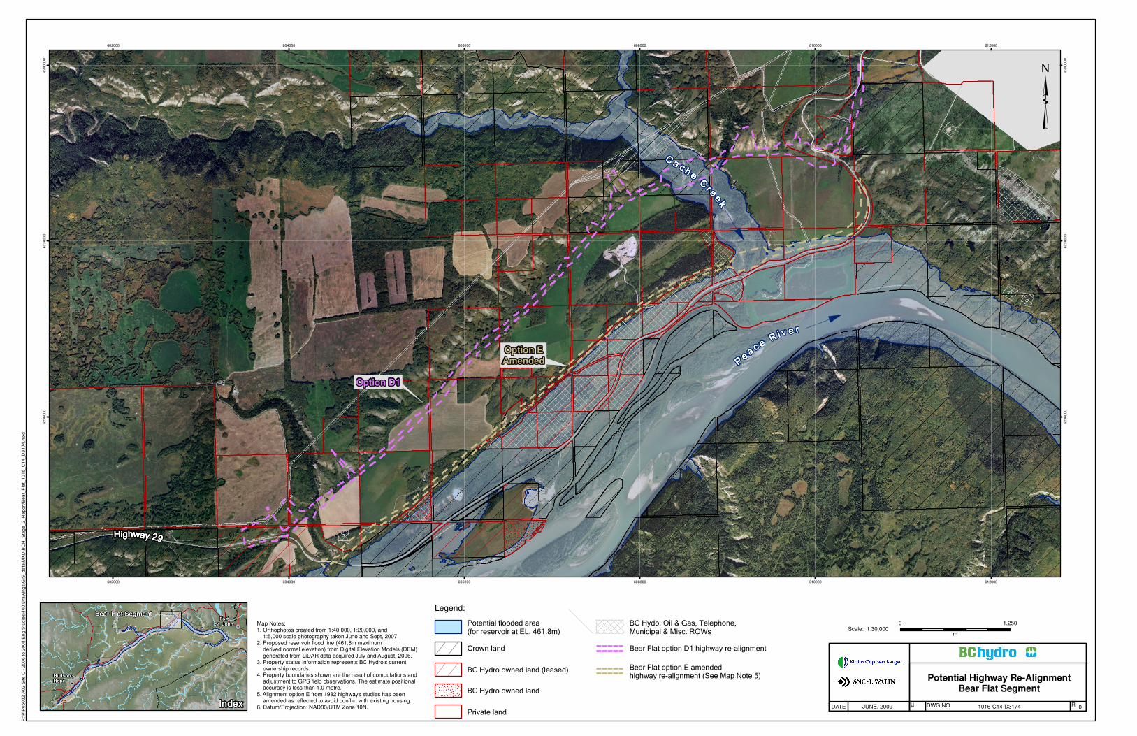
Potential Highway Re-AlignmentBear Flat Segment
1016-C14-D3174 0JUNE, 2009 µDATE DWG NO R
0 1,250
mScale: 1:30,000
Map Notes:1. Orthophotos created from 1:40,000, 1:20,000, and 1:5,000 scale photography taken June and Sept, 2007.2. Proposed reservoir flood line (461.8m maximum derived normal elevation) from Digital Elevation Models (DEM) generated from LiDAR data acquired July and August, 2006.3. Property status information represents BC Hydro's current ownership records.4. Property boundaries shown are the result of computations and adjustment to GPS field observations. The estimate positional accuracy is less than 1.0 metre.5. Alignment option E from 1982 highways studies has been amended as reflected to avoid conflict with existing housing.6. Datum/Projection: NAD83/UTM Zone 10N.
!.
Index
FortSt. John
Hudson'sHope
Bear Flat Segment
!.
!(29
Legend:
Potential flooded area(for reservoir at EL. 461.8m)
Crown land
Private land
BC Hydro owned land (leased)
BC Hydro owned land
³
Bear Flat option D1 highway re-alignment
Bear Flat option E amendedhighway re-alignment (See Map Note 5)
BC Hydo, Oil & Gas, Telephone,Municipal & Misc. ROWs


Peace River – Site C Hydro Project Highway 29 Relocations
APPENDIX II
Highway 29 Relocation, Hudson Hope To Charlie Lake – Urban Systems Report

PPEEAACCEE RRIIVVEERR SSIITTEE CC HHYYDDRROO PPRROOJJEECCTT
HHIIGGHHWWAAYY 2299 RREELLOOCCAATTIIOONN
HHUUDDSSOONN HHOOPPEE TTOO CCHHAARRLLIIEE LLAAKKEE
This report is prepared for the sole use of Klohn Crippen Berger. No
representations of any kind are made by Urban Systems Ltd. or its
employees to any party with whom Urban Systems Ltd. does not have a
contract.
2353 – 13353 Commerce Parkway Richmond, BC V6V 3A1 Phone: (604) 273-8700
Fax: (604) 273-8752

Page (i) 1896.0007.01 / November 2008
Klohn Crippen Berger Site C Hydro Project
Highway 29 Relocation
TABLE OF CONTENTS
1.0 EXECUTIVE SUMMARY........................................................................................................1
2.0 DESIGN CONSIDERATIONS................................................................................................2
2.1 LAND-USE .............................................................................................................................2
2.2 DESIGN STANDARDS .................................................................................................................3
2.3 HALFWAY RIVER AND BEAR FLAT .................................................................................................4
2.3.1 Halfway River (Attachie Flats) ..........................................................................................4
2.3.2 Bear Flats Section ...........................................................................................................5
2.4 LYNX CREEK TO FARRELL CREEK ..................................................................................................5
2.4.1 Lynx Creek .....................................................................................................................6
2.4.2 Farrell Creek ...................................................................................................................7
3.0 OTHER ISSUES AND IMPACTS............................................................................................8
3.1 STRUCTURAL REQUIREMENTS FOR MAJOR RIVER CROSSINGS ..............................................................8
3.2 HERITAGE RESOURCES AND ARCHAEOLOGY.....................................................................................8
3.3 GEOTECHNICAL – SOIL AND ROCK STABILIZATION............................................................................8
3.4 RIGHT OF WAY & PROPERTY IMPACTS ..........................................................................................9
3.5 LOCAL ROAD CONNECTIONS .......................................................................................................9
3.6 DRAINAGE AND UTILITIES ..........................................................................................................9
4.0 RECOMMENDATIONS AND NEXT STEPS ...........................................................................10

Page (1) 1896.0007.01 / November 2008
Klohn Crippen Berger Site C Hydro Project
Highway 29 Relocation
1.0 EXECUTIVE SUMMARY
Urban Systems (USL) has been requested by Klohn Crippen Berger Ltd. (KCBL), based on the
letter dated 28 November 2007, to provide updated Highway 29 realignment design as part of
the investigation to accommodate the proposed Peace River Site C Hydro Project for BC Hydro.
This report has been prepared to summarize the work undertaken for this assignment.
USL has reviewed the earlier work and reports for the relocation of Highway 29 to accommodate
the proposed Site C Hydro Development. This early work identified concept routes and evaluation
for the sections that would require realignment to suit the proposed Site C project. The following
reports were reviewed to provide a basis for the next stage of the work carried out under this
assignment.
• Highway 29 Hudson Hope to Charlie Lake. Environmental Impact and Engineering Study
of Highway 29 Relocation, Section 1. Completed by Graeme & Murray Consultants Ltd.,
dated January 1982; and
• Highway 29 Relocation Hudson Hope to Charlie Lake Section 2 by Wouldis Cunliffe Tait
and Delcan, dated February 1982.
These reports provided alternative alignments for each of the four sections of highway
realignment prepared. These sections are identified as: Lynx Creek, Farrell Creek, Halfway River
and Bear Flat.
The alignment alternative options from these reports have been carried forward for this
functional design stage. The results of the functional design carried out are summarized in this
report together with the design drawings and design issues associated with them.

Page (2) 1896.0007.01 / November 2008
Klohn Crippen Berger Site C Hydro Project
Highway 29 Relocation
2.0 DESIGN CONSIDERATIONS
The review of the 1982 relocation, Section 1 and Section 2 reports, identified a number of design
issues some of which were addressed at this stage. These issues relate primarily to the age of
the previous assessments and the standards applicable at that time. The major changes made at
this stage of design which have influenced alignment selection include:
• Land Use
• The latest BC MoT Standards
• Structural Requirements for Major River Crossings
• Geotechnical Assessment
Other issues assessed in the earlier reports, including archaeology, environmental and
hydrological assessments have not been revisited at this stage.
The functional design prepared has been based on recent Lidar survey. This level of survey detail
provided accurate information to help determine a suitable alignment and calculate cut/fill
quantities based on the current geotechnical assumptions.
2.1 Land-Use
Current alignments have been altered from the early options in some locations to avoid direct
impact to dwellings. No specific investigation was carried out for land use during this stage of
design and the information from the earlier reports should be updated during the next stage of
design. Some of the information on land noted in the earlier reports is summarized below.
In the Halfway River (Attachie Flat) and Bear Flat areas, land below the reservoir level is
generally owned by the Crown or BC Hydro. One location in the latter area was identified as
privately owned below reservoir level. Above the reservoir level land is generally privately owned
with five land owners in the two areas: one large 4,050 ha ranch in Attachie, and four areas in
Bear Flat ranging from 160 ha to 4,050 ha.
At the time of the earlier study twenty family dwellings were located in the Lynx Creek area,
although many of these were below the proposed reservoir level. Above the reservoir level the
proposed alignments passed through private land which had been cleared for residential use. On
the north bank of Lynx Creek the Alignment Option 2A traverses private agricultural land until it
meets the existing Highway.

Page (3) 1896.0007.01 / November 2008
Klohn Crippen Berger Site C Hydro Project
Highway 29 Relocation
The potential for recreational use and development was identified in a 1978 study into
recreational uses commissioned by BC Hydro. Lynx Creek was considered to have potential for
shoreline recreational facilities including a Marina. However the alignment option that would
facilitate the Marina was discounted on the basis of cost. A similar potential was identified in the
Cache Creek area. The potential for recreational uses has not been advanced during the current
design work.
2.2 Design standards
Design standards used for this assignment are based on the BC supplement to TAC. The current
design alignments have been based on the alignments from the earlier reports and modified to
suit the design standards noted. Alignments have also been moved at some locations to avoid
specific geotechnical or property impacts.
BC MoT requested a preferred design speed of 100 km/h with lower speed design allowed if
required in difficult terrain. The design criteria used for the preferred options is shown in Table 1
below.
Table 1
Design Criteria
Present
Conditions
Proposed
Criteria
Achieved
Criteria
Notes /
Comments
Classification RAU RAU RAU
Posted Speed varies 70 - 100 km/h 70 - 100 km/h Note 1.
Design Speed -- 70 - 100 km/h 70 - 100 km/h
Basic Lanes 2 2 2
Design Vehicle -- n/a Note 2.
Basic Lane Width 3.5m 3.6 m 3.6 m
Shoulder Width -- 2.0 m 2.0 m
Minimum Radius -- 190 - 440 m 340 m
Maximum Grade 10 % 7 % 7 %
Minimum Sag Curve -- 24 - 49 25
Minimum Crest Curve -- 36 – 74 47
Minimum S.S.D. -- 110 – 220 m 110 – 220 m Note 3.
Clear Zone -- 7.5 m 7.5 m
* Note 1. The design standards used for tie-in to existing at some locations matched existing. These lower speed locations would need speed advisory signs similar to those currently in place.
* Note 2. Details for intersections have not been designed under this assignment. A design vehicle was not required for the design prepared.
* Note 3. The minimum S.S.D. (stopping sight distance) was derived from the horizontal and vertical curve criteria used

Page (4) 1896.0007.01 / November 2008
Klohn Crippen Berger Site C Hydro Project
Highway 29 Relocation
2.3 Halfway River and Bear Flat
The easterly lengths of Highway 29 along the Peace River Valley which require relocation as a
result of impounding the Site C reservoir are located along the Attachie and Bear Flats areas.
The total length of the road affected in these areas is some 15 km.
Notable features in this section are:
• the two predicted slide areas: one to the west of the Halfway River; and the other
between Halfway River and Cache Creek;
• significant river crossings are required for both of these tributaries; and
• the descent alignment from the plateau.
The potential for wholesale realignment of the Highway along the plateau, involving 60 km of
new road construction, was discounted in the earlier study on the basis of high cost and impacts.
This possibility was revisited again at this stage of design during the initial review process but
was not pursued further as the rationale for the previous decision was still considered valid.
2.3.1 Halfway River (Attachie Flats)
The basic alignment options updated for this 4 km section of Highway 29 are as follows:
� Alignment Option A, from higher ground west of the Halfway River to the east bank at
the toe of the slope to the plateau. The Halfway River crossing has been set with a
profile approximately 30m above the low ground elevation. The crossing structure(s)
proposed at this location is covered separately in the Klohn Crippen Berger crossing
report. Apart from the river crossing area the road largely follows the existing ground
level. Highway gradients vary between 0.5% and 7%, with tie-in to an existing 10%
gradient.
� Alignment Option B, makes greater use of the existing Highway and follows the
reservoir shoreline as closely as possible. The estimated quantity of fill required is
reduced for this alternative although the alignment and its river crossing structure are
considerably more exposed to potential wave damage if a slide occurred on the east side
of the existing Attachie slide.
� Alignment Option C, a variation of Alignment A. This option utilizes a narrow crossing
point of the Halfway River, which results in a reduction in the volume of fill and/or
structure length associated with the river crossing. This alignment maintains the 100
km/h geometric design standard throughout its 4.2 km length.

Page (5) 1896.0007.01 / November 2008
Klohn Crippen Berger Site C Hydro Project
Highway 29 Relocation
2.3.2 Bear Flats Section
Two basic highway alignment options for this 10 km section of road have been selected from the
earlier study to carry forward at this stage. The initial alignments reviewed climbed the steep
slope to the top of the plateau to tie to the existing highway at the eastern end. The descent
from the plateau of this section presented a challenge to achieving the design standards, which
resulted in a number of initial tie-in options associated with the alignments. Most of these initial
options were judged unsuitable and not carried forward through the functional design level.
� Alignment Option D-D1, following the descent from the plateau at an approximate 9%
grade, follows the open toe of the slope, skirting the edge of the cultivated land and
through some wooded areas to Cache Creek. The crossing profile of Cache Creek is
approximately 50m above creek level.
� Alignment Option E Amended, is a modified version of the one identified as
Alignment E in the early study. The alignment has been shifted south of the original
Alignment E across Cache Creek in order to avoid existing residential buildings on the
east side of Cache Creek.
It essentially follows the future shoreline and makes greater use of the existing Highway,
skirting the edge of cultivated areas and through heavily wooded areas to Cache Creek.
The alignment follows the existing ground profile west of the Cache Creek gulley and is
raised east of this crossing. The road profile and structure across Cache Creek is
approximately 40m above the creek level.
It was identified that the unstable slope geology from the flat up to the plateau did not
favour the cuts and fill needed for an upgraded alignment in this area. As a result,
Alignment Option E Amended was shortened at the east end and tied into the existing
highway at the bottom of the flat. The resulting realignment length for this option is 6.9
km.
The horizontal geometry achieves a 100 km/h design standard along the length of the
relocated alignment. The vertical geometry reduces the design speed to 70 km/h, near
the west end at approximately Sta. 410+600, to reduce the cut in this area. The existing
highway east of the east tie-in has low speed vertical and horizontal geometry requiring
speed advisory signs.
2.4 Lynx Creek to Farrell Creek
Two lengths of Highway 29 are affected by reservoir impoundment in this area. These are Lynx
Creek to Slide Area A, approximately 7.7 km in length, and a relocated crossing at Farrell Creek
which has an approximate length of 2.5 km. Following the basic alignments prepared from the

Page (6) 1896.0007.01 / November 2008
Klohn Crippen Berger Site C Hydro Project
Highway 29 Relocation
earlier study, the options carried forward for this stage of design were updated based on current
design standards and new survey.
2.4.1 Lynx Creek
� Alignment Option A, ties to and shifts north from the existing highway approximately
900 m west of Lynx Creek. It crosses through wooded areas and farm land to the rear of
the terrace for approximately 3 km and then skirts the reservoir fill line before moving
toward the river to avoid impact to Slide Area A. The east end of the proposed alignment
ties into the existing highway past Slide Area A with an 80 km/h design vertical crest
curve.
� Alignment Option 1A ties to and shifts north from the existing highway approximately
1800 m west of Lynx Creek. It moves further north (west) than alignment A before
crossing Lynx Creek, impacting different residential properties. Approximately mid-way in
the realignment it meets and closely matches Alignment A through Slide Area A.
� Alignment Option B, the west end of this option follows the existing highway and the
reservoir shoreline more closely than Alignment A. Across Slide Area A the alignment
stays closer to the slope and out of the river. In the early study this alignment was
developed in response to concerns of local residents who considered that a lower creek
crossing would offer greater protection from wave action on the bank of properties
immediately adjacent to Lynx Creek.
� Alignment Option 2A, crosses Lynx Creek further south than Alignment A with less
property impacts in this area. East of Lynx Creek it shifts north to more closely match
Alignment A through the remaining realignment. The horizontal geometry meets a 100
km/h design standard throughout the realignment. A crest curve to tie to the existing
highway at the east end of the alignment has an 80 km/h design standard.
A significant feature in this section of realignment is the requirement to construct a new section
of road through Slide Area A. This is common to all alignment options and moves the highway
alignment towards the river.

Page (7) 1896.0007.01 / November 2008
Klohn Crippen Berger Site C Hydro Project
Highway 29 Relocation
2.4.2 Farrell Creek
Alignment Option Farrell Creek, this section, located 2 miles east of Slide Area A, was
identified in the early report as Alignment A. This option is the only one carried forward for this
stage of the functional design. The horizontal alignment leaves the west tie in on tangent and
continues straight for 2 km where it ties at the east with a large radius curve. The horizontal and
vertical geometry meets the 100 km/h design standard throughout the realignment length. The
design profile closely matches existing ground other than at the creek crossing where the profile
is approximately 25 m above the creek level.

Page (8) 1896.0007.01 / November 2008
Klohn Crippen Berger Site C Hydro Project
Highway 29 Relocation
3.0 OTHER ISSUES AND IMPACTS
3.1 Structural Requirements for Major River Crossings
Significant river crossings are required for the Halfway River, Cache Creek at Bear Flats, Lynx
Creek and Farrell Creek. These river crossings represent a significant component of the Highway
29 realignment and options for each crossing along specific alignments have been developed by
Klohn Crippen Berger Ltd. & SNC-Lavalin Inc..
The alignments selected with the earlier studies are heavily influenced by the river crossing
locations and the cost associated with them. A number of unknowns exist, e.g. the heritage and
archaeological values, the potential impacts from a slide induced wave and geotechnical
information, all of which require further investigation and analysis during the detailed design
process.
3.2 Heritage Resources and Archaeology
Consideration of heritage resources and archaeology is given in both the 1982 reports that
covered the Highway 29 realignments. Prior to these two studies, heritage resource impact
assessments were made in 1974 and 1978. These earlier assessments did include parts of the
terraces on Attachie and Bear Flats although the main focus of the work was the edge of terrace
and valley wall of Halfway River and Bear Flats in Section 1, and Farrell Creek and Lynx Creek in
Section 2.
No additional investigation on these items has been carried out during this stage.
3.3 Geotechnical – Soil and Rock Stabilization
Landslides have played a significant role in the development of the Peace River Valley. Some of
the valley slopes are marginally stable and there are many historic and currently active landslides
in both overburden and rock. There have been numerous slope stability problems along some
sections of Highway 29. The alignments have been refined during this stage of the design to try
and avoid impact to known slide areas or areas identified during site visits as having unstable
slopes. However, the requirements for stable slopes in both cut and fill would have to be
investigated further during the preliminary and detailed design process.
The use of 1V:3H cut slopes and 1V:2H fill slopes was recommended for the current design to
determine cut/fill toes and quantities. No specific additional geotechnical site investigation has
been incorporated into the design at this stage.

Page (9) 1896.0007.01 / November 2008
Klohn Crippen Berger Site C Hydro Project
Highway 29 Relocation
3.4 Right of Way & Property Impacts
Approximate Right of Way boundaries have been indicated on the plans at this time. These
boundaries were set using a 10 m offset from the calculated cut/fill toe lines which are expected
to cover the required ROW for the alignment as currently shown. Due to the limits of the
functional design carried out at this stage, these ROW lines should not be used for anything other
than a rough estimate of the actual property requirements.
These areas affected by the highway relocations cannot be used for property acquisition at this
stage due to the limited level of design and uncertainty of actual areas that would be required.
3.5 Local Road Connections
Design to show local road connections to Highway 29 realignments have not been carried out
during this stage of the highway design. There are however, no topographic constraints that
have been identified to indicate local road connections to the realigned highway would be a
concern.
3.6 Drainage and Utilities
Storm culverts along the road would be required for all realigned sections. Storm design has not
been carried out and quantities for storm at this stage are based on cross culverts every 300 m.
This spacing is based on BC MoT design guidelines.
BC Hydro lines parallel the highway in many areas and these lines would need to be relocated to
the new alignments. Costs for Hydro line relocations have not been included in this report.
No underground utility impacts have been identified during the course of this assignment.
