peak inspiratory and expiratory flow meterbme200/flow_meter_fall05/reports/final_report.… · peak...
TRANSCRIPT

Peak Inspiratory and Expiratory Flow Meter
BME 200/300 University of Wisconsin - Madison
December 7, 2005
Team: Darshan Patel, BSAC
Andrew Eley, Team Leader Sarah Offutt, Communications
Eric Bader, BWIG
Client: Christopher Green, MD Pediatric Pulmonology
UW Hospital
Advisor: Professor John Webster
Department of Biomedical Engineering University of Wisconsin

2
Table of Contents
ABSTRACT ................................................................................................................................................... 3 PROBLEM STATEMENT ............................................................................................................................ 3 BACKGROUND............................................................................................................................................ 3 DESIGN CONTRAINTS ............................................................................................................................... 6 ALTERNATIVE DESIGN 1 (DOUBLE BARREL) ..................................................................................... 7 ALTERNATIVE DESIGN 2 (TASER).......................................................................................................... 8 PROPOSED DESIGN 3 (SNIPER)................................................................................................................ 9 FINAL DESIGN........................................................................................................................................... 13 TESTING AND CALIBRATION................................................................................................................ 16 FUTURE WORK ......................................................................................................................................... 18 CONCLUSION ............................................................................................................................................ 19 REFERENCE ............................................................................................................................................... 20 APPENDIX A .............................................................................................................................................. 21 APPENDIX B............................................................................................................................................... 23
3
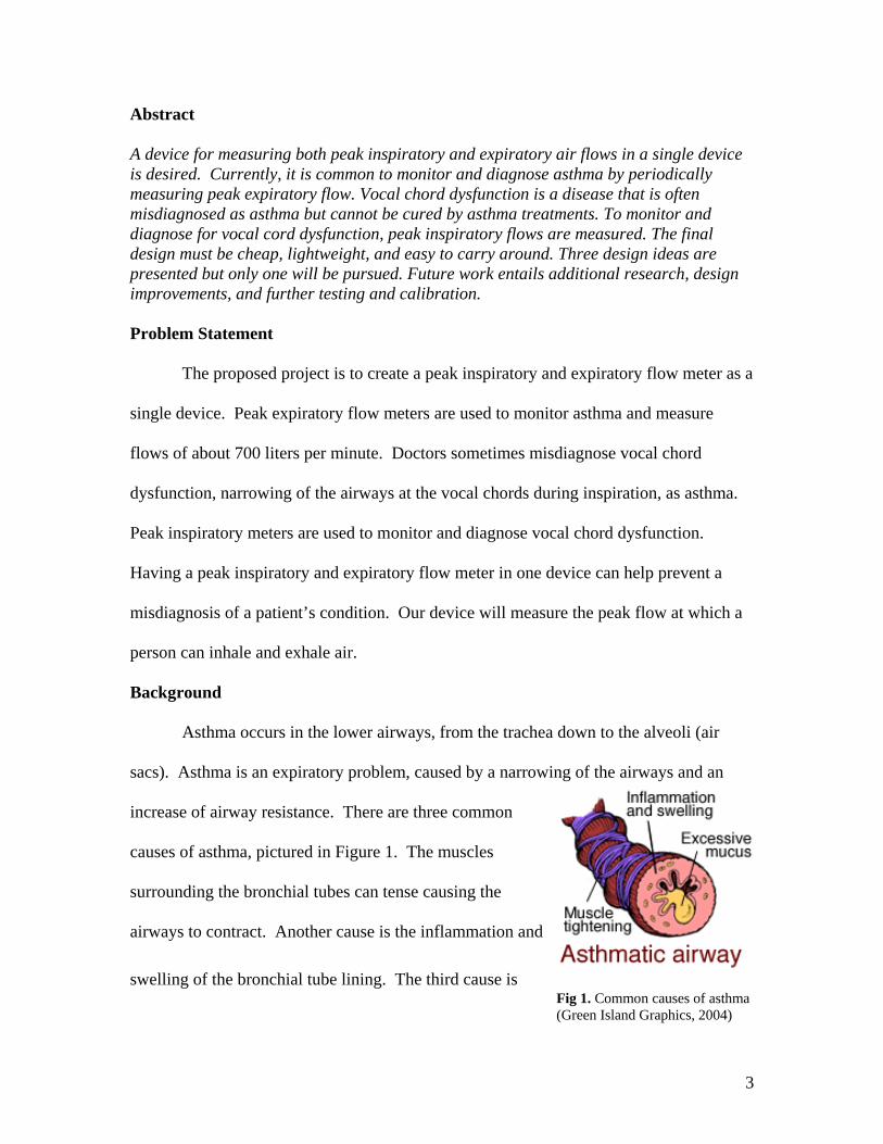
Fig 1. Common causes of asthma (Green Island Graphics, 2004)
Abstract
A device for measuring both peak inspiratory and expiratory air flows in a single device is desired. Currently, it is common to monitor and diagnose asthma by periodically measuring peak expiratory flow. Vocal chord dysfunction is a disease that is often misdiagnosed as asthma but cannot be cured by asthma treatments. To monitor and diagnose for vocal cord dysfunction, peak inspiratory flows are measured. The final design must be cheap, lightweight, and easy to carry around. Three design ideas are presented but only one will be pursued. Future work entails additional research, design improvements, and further testing and calibration. Problem Statement
The proposed project is to create a peak inspiratory and expiratory flow meter as a
single device. Peak expiratory flow meters are used to monitor asthma and measure
flows of about 700 liters per minute. Doctors sometimes misdiagnose vocal chord
dysfunction, narrowing of the airways at the vocal chords during inspiration, as asthma.
Peak inspiratory meters are used to monitor and diagnose vocal chord dysfunction.
Having a peak inspiratory and expiratory flow meter in one device can help prevent a
misdiagnosis of a patient’s condition. Our device will measure the peak flow at which a
person can inhale and exhale air.
Background
Asthma occurs in the lower airways, from the trachea down to the alveoli (air
sacs). Asthma is an expiratory problem, caused by a narrowing of the airways and an
increase of airway resistance. There are three common
causes of asthma, pictured in Figure 1. The muscles
surrounding the bronchial tubes can tense causing the
airways to contract. Another cause is the inflammation and
swelling of the bronchial tube lining. The third cause is

4
excess mucus production which fills the airway leaving a small opening for air to pass.
Asthma typically occurs in episodes following exposure to triggers such as exercise, cold,
or substances in the air (Framingham School, 2005). Asthma is a common condition
which is easy to treat and monitor. There are two measures taken to treat asthma,
medication for long term effect and medication for quick response. Long term asthma
medications, called anti-inflammatory agents reduce the swelling and sensitivity to
triggers. This medication is taken daily. Quick response medications, called
bronchodilators act principally to open the airways by relaxing bronchial muscle
(American Lung Association, 2005). In order to monitor asthma, doctors prescribe the
use of a peak expiratory flow meter.
Vocal cord dysfunction occurs in the upper airway, specifically the larynx. A
person with vocal cord dysfunction usually experiences difficulty inhaling. Vocal cord
dysfunction occurs when the vocal cords do not open and close properly during breathing
or speech (Allen, 2002). Typically this occurs during exercise or nervousness. Since the
symptoms (wheezing, and coughing) are similar to those of asthma, vocal cord
dysfunction gets misdiagnosed as asthma. Treatment for vocal cord dysfunction is
speech therapy. One way for doctors to diagnose this correctly is to measure peak
inspiratory flow.
Multiple designs of peak expiratory flow meters are on the market today, whereas
only a couple of inspiratory flow meters are available. Peak expiratory flow meters are
designed to help diagnose and monitor asthma. All of the expiratory flow meters are
similar in internal design but vary in outward appearance. The internal structure consists
of a thin plate or plunger attached to a spring. The plunger pushes up a lightweight

5
Fig. 2 Current flow meters
plastic indicator that corresponds to a flow rate in liters per minute. The force exerted by
exhaling moves the spring and plate. Along the side of the incremental ruler, are three
colored arrows. These arrows correlate to different zones and are specific to the user. If
user measures above the green they are in the controlled zone. Below the red zone is the
danger zone and a user should seek medical attention. Between these two in the yellow,
two peak flow readings in the yellow zone over a 48-hour period tell you that it may be
time to call your doctor for an adjustment in your medications (Allergy.com, 2005).
Each of the three peak expiratory flow meters, pictured in
Figure 2, have advantages and disadvantages that should be considered
for a final design. The far left design is from Personal Best. It comes
in a self contained case which makes it easy to carry around and keeps
it clean. Its shape is more rectangular allows it to fit easily in bags and
purses. The company also made it user friendly by making it
dishwasher safe. Air escapes from this design from the top which limits the complexity
of air loss in determining the flow rate. The middle design is from ASTech. It is
cylindrical in shape. It is by far the heaviest of the designs and is slightly awkward to
carry around. The advantage of this is it is more durable and presumably will last longer.
The design also has only air holes at the top. The last of the designs is the most portable
of the three. It is from a company called Spirometrics. It can fit easily in one’s pocket.
It is also dishwasher safe, which makes in more sanitary. This disadvantage in this
design is that the air can escape from holes on the outer perimeter of the circular airflow
way. This complicates the calibration of the flow rate. The other problem of having air
6
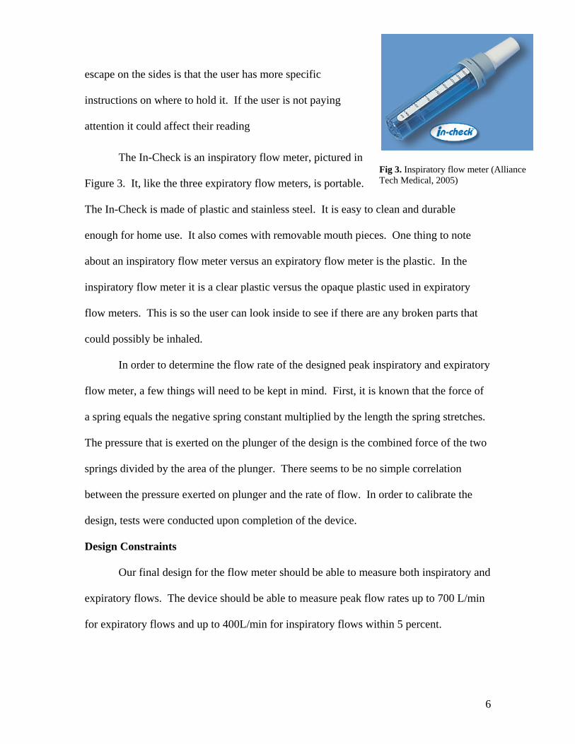
Fig 3. Inspiratory flow meter (Alliance Tech Medical, 2005)
escape on the sides is that the user has more specific
instructions on where to hold it. If the user is not paying
attention it could affect their reading
The In-Check is an inspiratory flow meter, pictured in
Figure 3. It, like the three expiratory flow meters, is portable.
The In-Check is made of plastic and stainless steel. It is easy to clean and durable
enough for home use. It also comes with removable mouth pieces. One thing to note
about an inspiratory flow meter versus an expiratory flow meter is the plastic. In the
inspiratory flow meter it is a clear plastic versus the opaque plastic used in expiratory
flow meters. This is so the user can look inside to see if there are any broken parts that
could possibly be inhaled.
In order to determine the flow rate of the designed peak inspiratory and expiratory
flow meter, a few things will need to be kept in mind. First, it is known that the force of
a spring equals the negative spring constant multiplied by the length the spring stretches.
The pressure that is exerted on the plunger of the design is the combined force of the two
springs divided by the area of the plunger. There seems to be no simple correlation
between the pressure exerted on plunger and the rate of flow. In order to calibrate the
design, tests were conducted upon completion of the device.
Design Constraints
Our final design for the flow meter should be able to measure both inspiratory and
expiratory flows. The device should be able to measure peak flow rates up to 700 L/min
for expiratory flows and up to 400L/min for inspiratory flows within 5 percent.
7
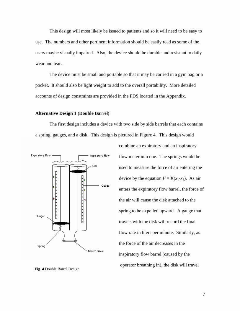
Fig. 4 Double Barrel Design
This design will most likely be issued to patients and so it will need to be easy to
use. The numbers and other pertinent information should be easily read as some of the
users maybe visually impaired. Also, the device should be durable and resistant to daily
wear and tear.
The device must be small and portable so that it may be carried in a gym bag or a
pocket. It should also be light weight to add to the overall portability. More detailed
accounts of design constraints are provided in the PDS located in the Appendix.
Alternative Design 1 (Double Barrel) The first design includes a device with two side by side barrels that each contains
a spring, gauges, and a disk. This design is pictured in Figure 4. This design would
combine an expiratory and an inspiratory
flow meter into one. The springs would be
used to measure the force of air entering the
device by the equation F = K(x1-x2). As air
enters the expiratory flow barrel, the force of
the air will cause the disk attached to the
spring to be expelled upward. A gauge that
travels with the disk will record the final
flow rate in liters per minute. Similarly, as
the force of the air decreases in the
inspiratory flow barrel (caused by the
operator breathing in), the disk will travel

8
down the barrel and a similar gauge will measure the inspiratory flow rate in liters/minute.
This design includes many advantages and disadvantages. First, this device
combines an inspiratory and an expiratory flow meter into one device. In addition, this
device is quite simple involving springs and disks. Disadvantages of this device include
a bulky design and two sets of everything can lead to faster failure rate. Furthermore,
more parts mean more expense to the manufacturer and the consumer. Finally, the
continual use of this device may cause the seals to fail which would lead to inaccurate
results. The disadvantages of this design make it clear that this is not the best choice.
Alternative Design 2 (Taser)
Our second alternative design was a drag flow peak detector that measures the
flow of air by measuring how much the plate is deflected. This design is shown in Figure
5 below. The device would consist of a plate that is attached to a stress gauge that
measures how much the plate is deflected from the original position. If the plate is
deflected in the negative y direction, the digital output would record the inspiratory flow
rate. When the plate is deflected in the positive y direction, the stress gauge will measure
the expiratory flow rate. This electronic device works by measuring how much stress
was placed on the plate by the force from the air. There is a direct correlation between
the amount that the plate is deflected and the incoming force of air. The stress gauge then
sends a reading to a digital output where the peak inspiratory and expiratory flow is
displayed.

9
Fig. 5 Taser design with digital displays and a defection plate with a strain gauge
Fig. 6 Proposed Sniper design will measure peak air flow by combining two springs on one plunger.
This alternative design seems like
it would be an excellent choice because
of the accurate determination of peak
flow, compact size, and an easy to read
display. When examining this device
more closely, the disadvantages of the
device make this an unlikely choice for
the proposal. The disadvantages include
electrical components which make the
device expensive, complex and more
likely to fail. In addition, this plan must be used
with extreme care to prevent damage to the
electronic gauges. Since our client would like this product to be used by children, the
electrical components make it an unsafe and an undesirable product.
Proposed Design 3 (Sniper)
The proposed
solution for a flow meter
would measure both
inspiratory and expiratory
flows in one breath. This is
ideal because there are no
current designs that
10
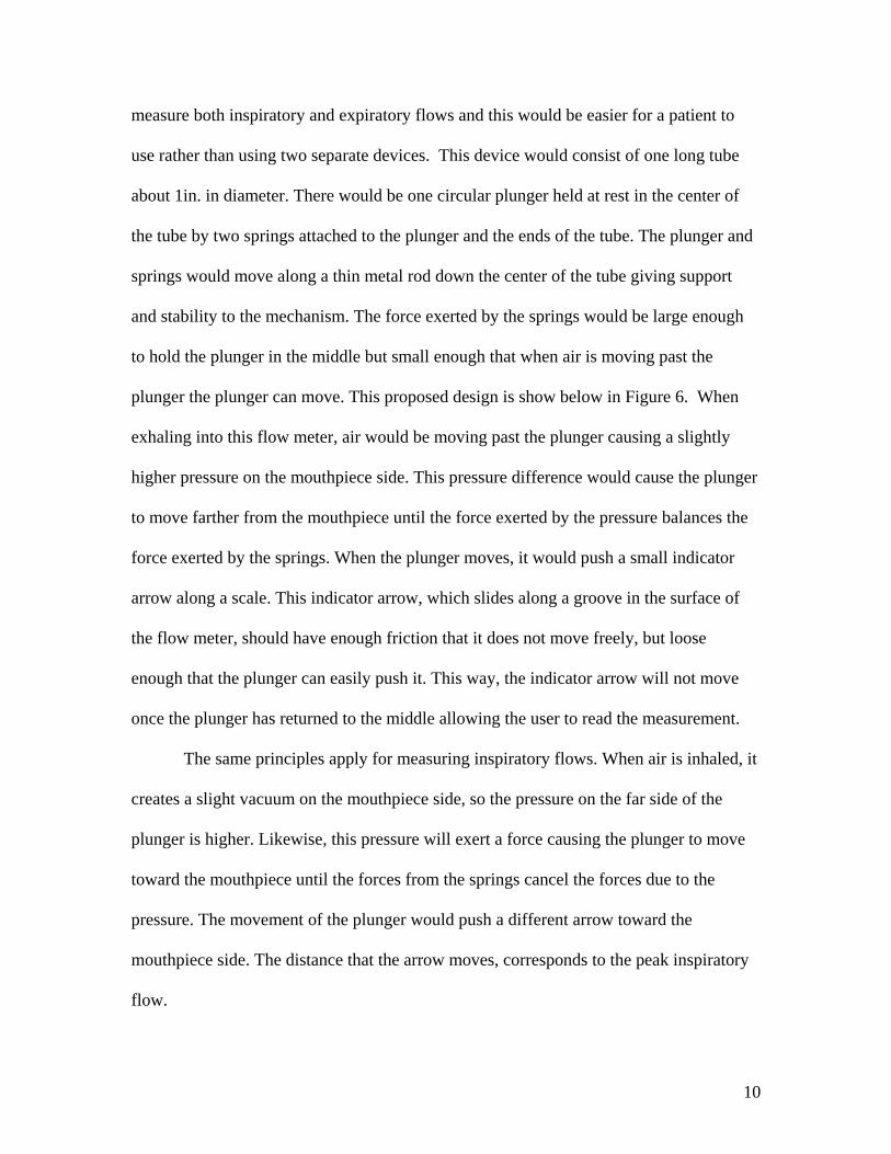
measure both inspiratory and expiratory flows and this would be easier for a patient to
use rather than using two separate devices. This device would consist of one long tube
about 1in. in diameter. There would be one circular plunger held at rest in the center of
the tube by two springs attached to the plunger and the ends of the tube. The plunger and
springs would move along a thin metal rod down the center of the tube giving support
and stability to the mechanism. The force exerted by the springs would be large enough
to hold the plunger in the middle but small enough that when air is moving past the
plunger the plunger can move. This proposed design is show below in Figure 6. When
exhaling into this flow meter, air would be moving past the plunger causing a slightly
higher pressure on the mouthpiece side. This pressure difference would cause the plunger
to move farther from the mouthpiece until the force exerted by the pressure balances the
force exerted by the springs. When the plunger moves, it would push a small indicator
arrow along a scale. This indicator arrow, which slides along a groove in the surface of
the flow meter, should have enough friction that it does not move freely, but loose
enough that the plunger can easily push it. This way, the indicator arrow will not move
once the plunger has returned to the middle allowing the user to read the measurement.
The same principles apply for measuring inspiratory flows. When air is inhaled, it
creates a slight vacuum on the mouthpiece side, so the pressure on the far side of the
plunger is higher. Likewise, this pressure will exert a force causing the plunger to move
toward the mouthpiece until the forces from the springs cancel the forces due to the
pressure. The movement of the plunger would push a different arrow toward the
mouthpiece side. The distance that the arrow moves, corresponds to the peak inspiratory
flow.

11
This flow meter would ultimately be made of cheap lightweight plastics. Only the
springs and rod would be made of metal. The total length of the device should be no
longer than eight inches. It would have smooth edges and made of a clear plastic so if
something were broken or loose it could be easily spotted.
This design has advantages and disadvantages just like any other design. A key
feature in this design is its combined functions. Inspiratory and expiratory flows are
measured in the same compartment which reduces space, parts, and therefore cost.
Because only one plunger is used and moves two directions, fewer parts are needed
which improves the reliability and life of the product. There are also no electrical parts
making it less complicated. The only disadvantage of this design is that because the
inspiratory and expiratory scales are in a line, the total length of the device will be longer.
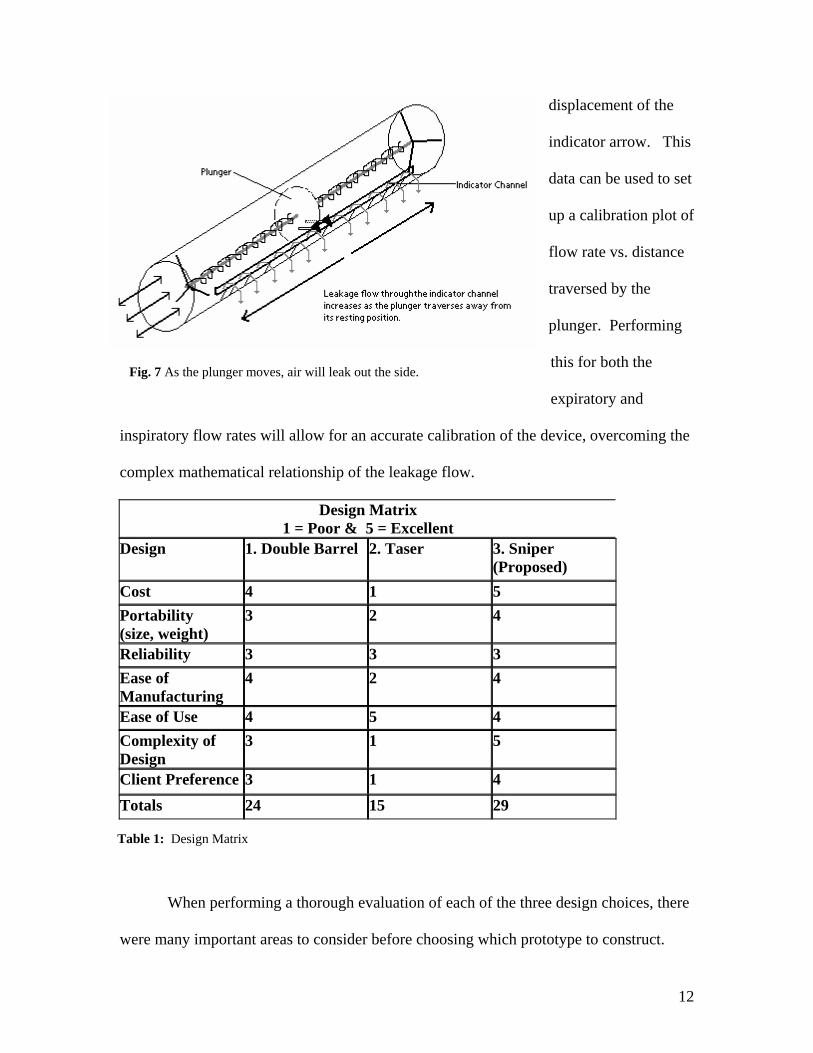
A problem with this design is that the indicator channel is an incision in the
tubular enclosure. Because of this, as air flows into or out of the end of the tube there will
be some leakage of flow through the indicator channel. In addition the rate at which
leakage occurs will not be a linear relationship. As the plunger moves away from the
resting position the area between the incision and the plunger increases, which causes the
leakage flow to increase as the plunger traverses away from the resting position. This is
illustrated in Figure 7. This makes it more difficult to make a mathematical model of
flow rate, thus making it more difficult to accurately make the indicator calibration
markers on the side of the tube.
To overcome this difficulty the device can be calibrated manually using a device
that generates a known amount of air flow (rotameter). By administering a series of
flows we can physically measure how much the plunger traversed by measuring the
12
Fig. 7 As the plunger moves, air will leak out the side.
Table 1: Design Matrix
displacement of the
indicator arrow. This
data can be used to set
up a calibration plot of
flow rate vs. distance
traversed by the
plunger. Performing
this for both the
expiratory and
inspiratory flow rates will allow for an accurate calibration of the device, overcoming the
complex mathematical relationship of the leakage flow.
Design Matrix 1 = Poor & 5 = Excellent
Design 1. Double Barrel 2. Taser 3. Sniper (Proposed)
Cost 4 1 5 Portability (size, weight)
3 2 4
Reliability 3 3 3 Ease of Manufacturing
4 2 4
Ease of Use 4 5 4 Complexity of Design
3 1 5
Client Preference 3 1 4 Totals 24 15 29
When performing a thorough evaluation of each of the three design choices, there
were many important areas to consider before choosing which prototype to construct.

13
This first and probably the most important was the cost of the project. The client
specifically stated that he would like a cheap device that could be given away by the
hospital or could be purchased if needed. Out of the three plans, the sniper design had
the best rating on the total cost. Another important area to examine was the ease of use
of each design. According to Table 1, the Taser design had the highest rating for this
area since all of the outputs would have been digitally displayed. The other two models
still had decent ratings but were slightly less since the results would have to be read using
a scale that was located on the device. Furthermore, the client stated that the portability
of the device was extremely important. He wanted the device to be light and small so
that it would not be a hindrance when carried to places like sporting events, family
gatherings, and school. His concern was that if it’s hard to carry, then the patients will
leave them at home. The sniper design had the highest rating since it was the most
compact in size and lightest in weight. After a thorough evaluation of each design, the
sniper design met all of the required constraints. A summary of the designs is provided
in the design matrix shown in Table 1 above.
Final Design
Following the mid-semester presentation, our team considered the alternative
designs, and spoke with our client. We decided to pursue our third design as our final
design. We found that we could construct a simple prototype from the flow meters we
currently had, but we still designed our own prototype using different materials.
The next step our team took after the mid-semester presentations, was to find the
proper materials we would need. The most difficult part to get was the spring. Exhaustive
research was done to look for the correct spring we needed since it is very specialized.

14
Fig 8: Prototype of altered design
After no spring could be found, it was determined that the best solution would be to use
springs from the current designs. In speaking to our client, he was able to order us four
flow meters made by Personal Best. Upon taking these flow meters apart, we saw that it
would be easy to construct a simple prototype out of these parts to see that our design
would work. The plunger, spring, and indicator arrow was carefully removed from one
flow meter and attached to a
second. Since the spring and
plunger were attached, it was
easiest to directly epoxy the face
of the plunger to the face of the
other plunger in the other flow
meter, as seen in Figure 8. The
indicator arrow was then inserted into the flow meter on the opposite side of the plunger
from the original indicator arrow.
When this was completed the two halves of the flow meter were snapped back
together and testing was done. Testing consisted of a team member inhaling and exhaling
in the flow meter to see how the results compared to a regular flow meter. It was found
that a peak expiratory flow of about 550 L/min only moved the plunger 2.5 cm which is
half of the available room, while an inspiratory flow caused the plunger to max out. This
is because when exhaling, the plunger moves up allowing more air to escape through the
slit holding the indicator arrow, thus producing less force on the plunger, but when
inhaling, the plunger moves down, causing less air to escape and causing more force on
the plunger. Our solution was to increase the overall length of the flow meter, which
15
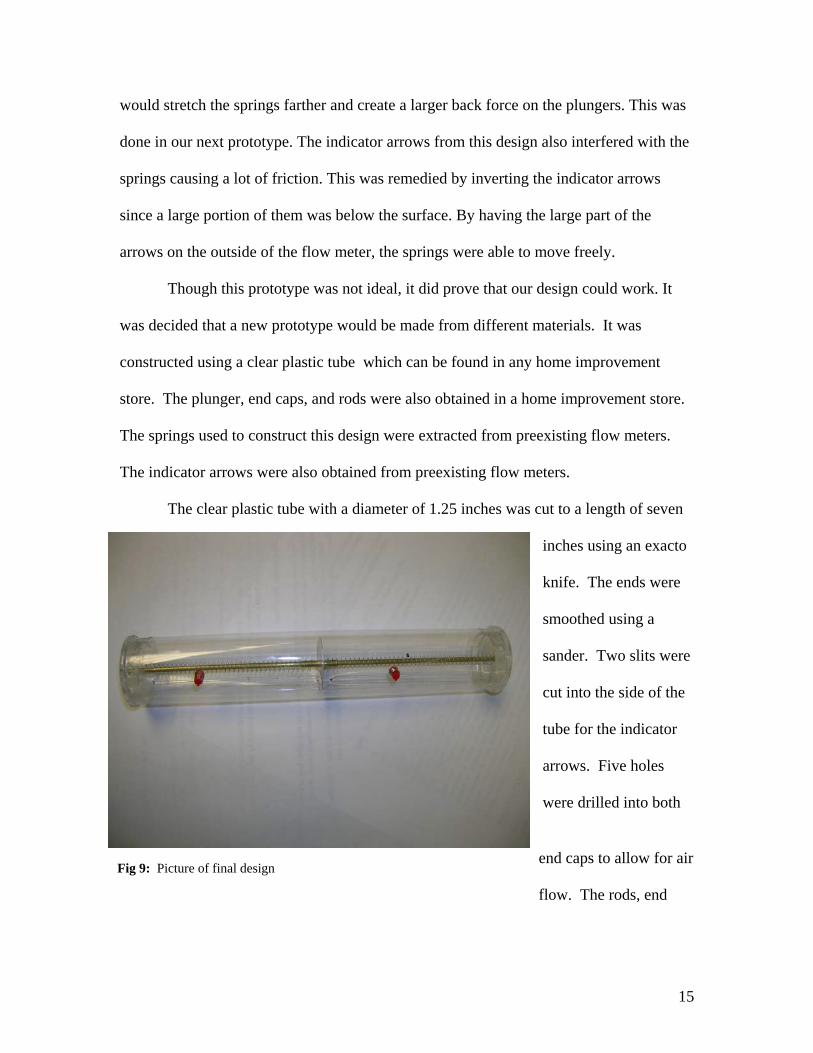
Fig 9: Picture of final design
would stretch the springs farther and create a larger back force on the plungers. This was
done in our next prototype. The indicator arrows from this design also interfered with the
springs causing a lot of friction. This was remedied by inverting the indicator arrows
since a large portion of them was below the surface. By having the large part of the
arrows on the outside of the flow meter, the springs were able to move freely.
Though this prototype was not ideal, it did prove that our design could work. It
was decided that a new prototype would be made from different materials. It was
constructed using a clear plastic tube which can be found in any home improvement
store. The plunger, end caps, and rods were also obtained in a home improvement store.
The springs used to construct this design were extracted from preexisting flow meters.
The indicator arrows were also obtained from preexisting flow meters.
The clear plastic tube with a diameter of 1.25 inches was cut to a length of seven
inches using an exacto
knife. The ends were
smoothed using a
sander. Two slits were
cut into the side of the
tube for the indicator
arrows. Five holes
were drilled into both
end caps to allow for air
flow. The rods, end

16
Table 2: Calibration data for inspiratory flows.
Table 3: Calibration data for expiratory flows.
Fig. 10 Testing and calibration of flow meter.
caps, and tube were glued together using epoxy. These pieces were assembled as shown
in Figure 9.
Testing and Calibration
Our final prototype design was tested in MSC using a rotameter as show below in
Figure 10. This device was able to exert a flow of air which was used to test and
calibrate expiratory flow, and it also created a vacuum
which was used to test and calibrate inspiratory flows.
Flow rate data was collected for both the
inspiratory and expiratory flows. A series of different
flow rates were used, and for each flow rate the
distance that the plunger traversed was recorded. This
data is shown below in Tables 2 and 3.
Inspiratory Flow Calibration Data Flow (L/min) Distance Traversed (cm) 148.2 0.6 199.8 1.1 270 2.1 326.4 3.3 384.6 5.4 399.6 6.12
Expiratory Flow Calibration Data Flow (L/min) Distance Traversed (cm) 116.4 1.5 163.8 2.6 226.2 3.7 250.2 5.6 270.6 6.65

17
Peak Inspiratory Flow Calibration Curve
y = 0.1708e0.009x
R2 = 0.996
0
1
2
3
4
5
6
7
0 50 100 150 200 250 300 350 400 450
Flow (L/min)
Dis
tanc
e Tr
aver
sed
(cm
)
Peak Expiratory Flow Calibration Curve
y = 0.5213e0.0093x
R2 = 0.9782
0
1
2
3
4
5
6
7
0 50 100 150 200 250 300
Flow (L/min)
Dis
tanc
e Tr
aver
sed
(cm
)
Fig. 11 Calibration curve for inspiratory flows.
Fig. 12 Calibration curve for expiratory flows.
This data was then plotted using an excel spreadsheet. The data points were
fitted to a natural exponential function. The plots and the exponential fit for both the
inspiratory and expiratory flows are shown below in Figures 11 and 12.
18
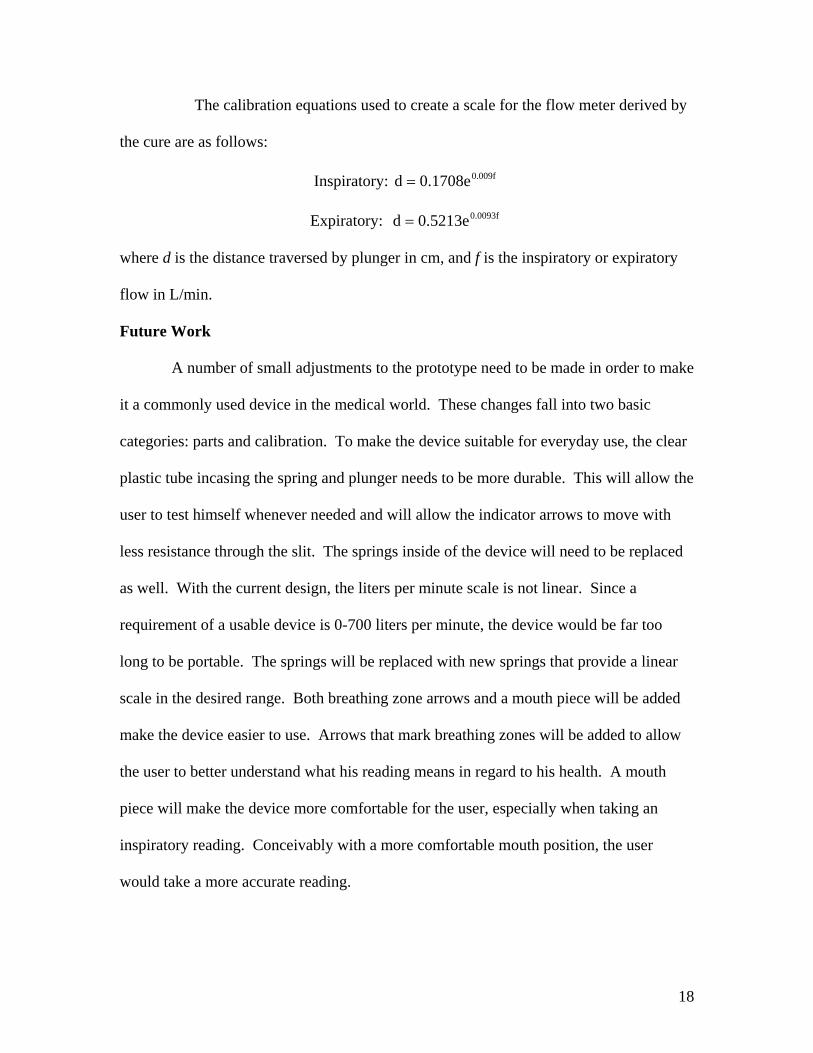
The calibration equations used to create a scale for the flow meter derived by
the cure are as follows:
Inspiratory: 0.009f0.1708ed =
Expiratory: 0.0093f0.5213ed =
where d is the distance traversed by plunger in cm, and f is the inspiratory or expiratory
flow in L/min.
Future Work
A number of small adjustments to the prototype need to be made in order to make
it a commonly used device in the medical world. These changes fall into two basic
categories: parts and calibration. To make the device suitable for everyday use, the clear
plastic tube incasing the spring and plunger needs to be more durable. This will allow the
user to test himself whenever needed and will allow the indicator arrows to move with
less resistance through the slit. The springs inside of the device will need to be replaced
as well. With the current design, the liters per minute scale is not linear. Since a
requirement of a usable device is 0-700 liters per minute, the device would be far too
long to be portable. The springs will be replaced with new springs that provide a linear
scale in the desired range. Both breathing zone arrows and a mouth piece will be added
make the device easier to use. Arrows that mark breathing zones will be added to allow
the user to better understand what his reading means in regard to his health. A mouth
piece will make the device more comfortable for the user, especially when taking an
inspiratory reading. Conceivably with a more comfortable mouth position, the user
would take a more accurate reading.

19
As a whole, the way that calibration was gone about would need to be changed.
The use of a rotamotor proved to be insufficient. When using other flow meters a group
member averaged 500 liters per minute. By the same force, using the scale the rotamotor
calibrated, he averaged 200 liters per minute. There was a difference between the way
the rotamotor exerted air and the way a user would exert air, which is believe to account
for the differences in the measurements. The rotamotor is a constant supply that slowly
builds up to a measured liters per minute, where as user gives a quick burst of air. To
recalibrate the device, a machine that delivers a quick burst of air will be used. By
mimicking the way the device is used in the everyday world, a usable scale will be
obtained. The calibrating will be done multiple times to increase the accuracy of the
scale. Upon completion of all the changes, a patent will be sought after and marketed to
companies to manufacture for daily use.
Conclusion
The device that was created measures peak inspiratory and peak expiratory flow.
This device can be used by medical professionals to diagnose both asthma and vocal
chord dysfunction. Our device is simple and easily reproduced using everyday items.
Despite our device being able to measure both inspiratory and expiratory flows, further
testing and development needs to be conducted.

20
Reference Allen, James MD. (2002). Vocal Cord Dysfunction. Retrieved October 2, 2005, from
http://home.columbus.rr.com/allen/vocal_cord_dysfunction.htm.
American Lung Association. (2005, July). Asthma in Adults Fact Sheet. Retrieved
October 2, 2005, from http://www.lungusa.org/site/pp.asp?c=dvLUK9O0E&b=22596.
Framingham School. (2005, June). Framingham School Health Services: Asthma.
Retrieved October 2, 2005. from http://www.framingham.k12.ma.us/schoolhealth/health_info/Asthma.htm.
Figures
Alliance Tech Medical. (2005). In-Check. Retrieved September 17, 2005, from
http://www.alliancetechmedical.com/inck.html. Green Island Graphics (2004, December). Causes of Asthma. Retrieved October 2, 2005
from http://www.greenislandgraphics.com/kp_asthma/under_causes.html.

21
Appendix A
Product Design Specifications September 29, 2005
Inspiratory and expiratory flow meter –Product Design Specifications
Team: Andrew Eley (Leader) Sarah Offutt (Communicator) Darshan Patel (BSAC) Eric Bader (BWIG) Function: Our client desires a peak inspiratory and peak expiratory flow meter in a
single device to monitor for symptoms of asthma and vocal cord dysfunction. It should measure flows up to about 700 liters per second for adults, be cheap, durable, and easy to use with clear measurement readings.
Client requirements: . • measure both inspiratory and expiratory peak flow in a single device . • cheap to make . • Easy to read measurements . • Cannot compromise patient or user safety Design requirements:
1. Physical and operational characteristics a. Performance requirements: The design must be able to measure
inspiratory and expiratory peak flow rates. b. Safety: The design must not have materials that could be harmful to
patient. c. Accuracy and reliability: This device should measure peak flow rates to
about 700 L/min for expiratory and to about 400L/min for inspiratory to within 5 percent.
d. Life in service: The final design will be given to patients who may use them daily for a period of time and then disposed of.
e. Shelf life: The design should last indefinitely. f. Operating environment: The design must be easily sanitized for normal
daily use by a patient. g. Ergonomics: The design must be portable and easily held up to the mouth
in one hand. h. Size: The design must be small and easily portable. It may be thrown in a
gym bag or a pocket. i. Weight: The design must be light enough to hold up to the mouth and

22
carry around. Should not exceed 2 lbs. j. Materials: The design should be made primarily of cheap lightweight
plastics. k. Aesthetics, appearance, and finish: The device should look easy to use
with no rough surfaces. Should be easily understandable. 2. Product characteristics:
a. Quantity: One model will be prototyped; if successful, it can be manufactured and used for future use.
b. Target product cost: The cost of the entire device once in manufacturing should be less then $40.
3. Miscellaneous:
a. Standards and specifications: May need FDA approval. b. Customer: The client would prefer the model to be inexpensive, light, and
easy to read. c. Patient-related concerns: Must be able to be easily cleaned. Possibly
dishwasher safe.

23
Appendix B Project Expenses: Clear Plastic Tube $1.97 End Caps-Plunger $1.96 Solid Metal Rod $0.82 Connecting Rod $0.30 Springs Free Total Expenses $5.05