peak satellite-to-earth data rates derived from
TRANSCRIPT

David G. LandonL-3 Communication Systems-West, Salt Lake City, Utah
Rainee N. Simons and Edwin G. WintuckyGlenn Research Center, Cleveland, Ohio
Jun Y. Sun, James S. Winn, Stephen A. Laraway, William K. McIntire, John L. Metz, and Francis J. SmithL-3 Communication Systems-West, Salt Lake City, Utah
Peak Satellite-to-Earth Data Rates Derived From Measurements of a 20 Gbps Bread-Board Modem
NASA/TM—2011-217241
November 2011

NASA STI Program . . . in Profi le
Since its founding, NASA has been dedicated to the advancement of aeronautics and space science. The NASA Scientifi c and Technical Information (STI) program plays a key part in helping NASA maintain this important role.
The NASA STI Program operates under the auspices of the Agency Chief Information Offi cer. It collects, organizes, provides for archiving, and disseminates NASA’s STI. The NASA STI program provides access to the NASA Aeronautics and Space Database and its public interface, the NASA Technical Reports Server, thus providing one of the largest collections of aeronautical and space science STI in the world. Results are published in both non-NASA channels and by NASA in the NASA STI Report Series, which includes the following report types: • TECHNICAL PUBLICATION. Reports of
completed research or a major signifi cant phase of research that present the results of NASA programs and include extensive data or theoretical analysis. Includes compilations of signifi cant scientifi c and technical data and information deemed to be of continuing reference value. NASA counterpart of peer-reviewed formal professional papers but has less stringent limitations on manuscript length and extent of graphic presentations.
• TECHNICAL MEMORANDUM. Scientifi c
and technical fi ndings that are preliminary or of specialized interest, e.g., quick release reports, working papers, and bibliographies that contain minimal annotation. Does not contain extensive analysis.
• CONTRACTOR REPORT. Scientifi c and
technical fi ndings by NASA-sponsored contractors and grantees.
• CONFERENCE PUBLICATION. Collected papers from scientifi c and technical conferences, symposia, seminars, or other meetings sponsored or cosponsored by NASA.
• SPECIAL PUBLICATION. Scientifi c,
technical, or historical information from NASA programs, projects, and missions, often concerned with subjects having substantial public interest.
• TECHNICAL TRANSLATION. English-
language translations of foreign scientifi c and technical material pertinent to NASA’s mission.
Specialized services also include creating custom thesauri, building customized databases, organizing and publishing research results.
For more information about the NASA STI program, see the following:
• Access the NASA STI program home page at http://www.sti.nasa.gov
• E-mail your question via the Internet to help@
sti.nasa.gov • Fax your question to the NASA STI Help Desk
at 443–757–5803 • Telephone the NASA STI Help Desk at 443–757–5802 • Write to:
NASA Center for AeroSpace Information (CASI) 7115 Standard Drive Hanover, MD 21076–1320

David G. LandonL-3 Communication Systems-West, Salt Lake City, Utah
Rainee N. Simons and Edwin G. WintuckyGlenn Research Center, Cleveland, Ohio
Jun Y. Sun, James S. Winn, Stephen A. Laraway, William K. McIntire, John L. Metz, and Francis J. SmithL-3 Communication Systems-West, Salt Lake City, Utah
Peak Satellite-to-Earth Data Rates Derived From Measurements of a 20 Gbps Bread-Board Modem
NASA/TM—2011-217241
November 2011
National Aeronautics andSpace Administration
Glenn Research CenterCleveland, Ohio 44135
Prepared for theMILCOM 2011cosponsored by Armed Forces Communications Electronics Association andIEEE Communications SocietyBaltimore, Maryland, November 7–10, 2011

Available from
NASA Center for Aerospace Information7115 Standard DriveHanover, MD 21076–1320
National Technical Information Service5301 Shawnee Road
Alexandria, VA 22312
Available electronically at http://www.sti.nasa.gov
Trade names and trademarks are used in this report for identifi cation only. Their usage does not constitute an offi cial endorsement, either expressed or implied, by the National Aeronautics and
Space Administration.
Level of Review: This material has been technically reviewed by technical management.
This report contains preliminary fi ndings, subject to revision as analysis proceeds.

NASA/TM—2011-217241 1
Peak Satellite-to-Earth Data Rates Derived From Measurements of a 20 Gbps Bread-Board Modem
David G. Landon L-3 Communication Systems-West
Salt Lake City, Utah 84116
Rainee N. Simons and Edwin G. Wintucky National Aeronautics and Space Administration
Glenn Research Center Cleveland, Ohio 44135
Jun Y. Sun, James S. Winn, Stephen A. Laraway, William K. McIntire, John L. Metz, and Francis J. Smith L-3 Communication Systems-West
Salt Lake City, Utah 84116
Abstract
A prototype data link using a Ka-band space qualified, high efficiency 200 W TWT amplifier and a bread-board modem emulator were created to explore the feasibility of very high speed communications in satellite-to-earth applications. Experiments were conducted using a DVB-S2-like waveform with modifications to support up to 20 Gbps through the addition of 128 Quadrature Amplitude Modulation (QAM).
Limited by the bandwidth of the amplifier, a constant peak symbol rate of 3.2 Giga-symbols/sec was selected and the modulation order was varied to explore what peak data rate might be supported by an RF link through this amplifier. Using 128-QAM, an implementation loss of 3 dB was observed at 20 Gbps, and the loss decreased as data rate or bandwidth were reduced. Building on this measured data, realistic link budget calculations were completed. Low-Earth orbit (LEO) missions based on this TWTA with reasonable hardware assumptions and antenna sizing are found to be bandwidth-limited, rather than power-limited, making the spectral efficiency of 9/10-rate encoded 128-QAM very attractive. Assuming a bandwidth allocation of 1 GHz, these computations indicate that low-Earth orbit vehicles could achieve data rates up to 5 Gbps—an order of magnitude beyond the current state-of-practice, yet still within the processing power of a current FPGA-based software-defined modem. The measured performance results and a description of the experimental setup are presented to support these conclusions.
I. Introduction
Multiple Gigabit per second (Gbps) data rates are of considerable interest to both government and commercial customers, as evidenced in the roadmap of NASA’s Space Communications and Navigation (SCaN) program office (Ref. 1). The justification for higher data rates is closely linked to the capabilities of spacecraft sensors, which are quickly outstripping the ability of current data links to move
the sensor information back to earth. In response NASA has conducted studies and experiments to increase the capacity of the data links (Ref. 2). Notable progress has been achieved (Ref. 3), and space-to-ground data links are becoming faster, but not yet sufficiently so as to satisfy all sensor requirements (Refs. 4 and 5).
Achieving such high data rates is dependant on both the spacecraft effective isotropic radiated power (EIRP) and the waveform (constellation order and forward error correction). Without sufficient power, the data link will always operate in a power-limited mode, whereas, without the correct waveform, the data link may become bandwidth-limited. By managing both the power and bandwidth, the data link performance can achieve nearly the modulation-constrained Shannon capacity limit (Ref. 6) and remain within the regulatory allocated bandwidth.
NASA Glenn Research Center has developed space qualified, high power, high efficiency, Ka-band traveling-wave tube amplifiers (TWTAs) for several missions including Cassini and ones to Mars, Jupiter, the Moon, and the International Space Station (ISS). Amplifier efficiencies have progressed from 41 percent for the Cassini design to as high as 62 percent for the Jupiter mission with RF power levels of 10 to 200 W. Typical design bandwidths have been 500 MHz or less, but as shown later, the amplifiers perform well to bandwidths of at least 3 GHz.
The results reported here focus on the digital video broadcasting—satellite—second generation (DVB-S2) (Ref. 7) waveform family. Using the DVB-S2 constellations—quadrature phase shift keying (QPSK) to 32-amplitude phase shift keying (APSK)—and the 9/10-rate FEC code as a starting point, we have extended the specification to a data rate of at least 20 Gbps by adding two higher order constellations, 64-APSK, and 128-QAM.
The paper proceeds as follows. In Section II, the waveform features and the hardware implementation are described. Section III briefly explains the modem emulator technology, a method of testing waveforms without a full commitment to hardware (i.e., a breadboard modem). Section IV describes the equipment used to measure the performance of the data link

NASA/TM—2011-217241 2
and Section V presents experimental results. Finally, Section VI gives link budget results that rely on the measured performance to compute the maximum data rates that are feasible for four different types of space missions.
II. Waveform Design and Implementation
Details of the DVB-S2 modulation, constellation mapping, interleaving, and encoding for QPSK, 8-PSK, 16-APSK, and 32-APSK modes are available in (Ref. 7). Higher spectral efficiencies are available through 64-APSK and 128-QAM.
In the processes of adding the higher order constellations, we observed that bit error rate (BER) performance is surprisingly sensitive to the constellation mapping by comparing the BER performance of the DVB-S2 constellation for 32-APSK with an alternative 32-APSK constellation with the same bit mapping, but equally spaced points. We make no claim that our extensions of the DVB-S2 modulation suite to higher-order modulations have optimized constellations and welcome further contributions to the literature on this topic. Rather than presenting additional candidates for these modulation types, we use the 64-APSK constellation given in (Ref. 8), and the 128-QAM cross II constellation from (Ref. 9).
Although results in this paper rely primarily on breadboard modem emulation measurements, we are in the process of implementing the same waveform at a reduced rate on an existing L-3 FPGA-based hardware modem (Ref. 10). Raising the hardware rate to 20 Gbps exceeds current funding objectives but harmonizes with the current hardware architecture. Current firmware loads of the FPGAs support QPSK, 8-PSK, 16-APSK, 32-APSK, and 64-APSK and (120,128)2 (Refs. 11 and 12) turbo product code (TPC) with a throughput limitation of 4.5 Gbps. Implementation losses can be kept reasonable at higher order modulation in this same software-defined radio (SDR) to support throughputs similar to those studied in this paper.
The SDR is a two-module (transmit and receive) solution (Fig. 1). The analog interface is baseband I/Q-sampled with X-band up-conversion for the transmit module and down-conversion for the receive module. The modules use 3.5 Giga-sample/sec A/Ds and D/As, and could process a 3.2 GHz RF bandwidth with a change in the analog filter.
We have implemented a DVB-S2 modulator and encoder on another platform in a single Virtex-2 Pro 100 FPGA, an older member of the Xilinx family. Although that design can encode data at over 1 Gbps, in the faster SDR described here the extension to 8 Gbps is a relatively straightforward firmware change. A boost to 10 Gbps is enabled by spreading processing across two modules via I/O devoted to inter-module communication and 20 Gbps could be achieved with additional firmware modifications.
An L-band, IF-sampled version of this modem was used to test the limits of the wideband Tracking and Data Relay Satellites System (TDRSS) channel. In April 2010, L-3 and NASA conducted high data rate demonstrations from the Radio Frequency Simulation Operations Center (RFSOC) at Goddard Space Flight Center (GSFC) over TDRSS F10 into White Sands Complex (Ref. 3). Figure 2 indicates that hardware performance was only 1.75 dB from theory in spite of the broadband and non-linear distortions of the double-hop channel and RF equipment. Modest data rate increases are possible, but the TDRSS RF filters significantly attenuate higher rates and can lead to considerable losses.
III. Modem Emulation
Rather than limiting hardware characterization and algorithm validation to modes currently implemented in the SDR, we also rely on precise hardware emulation tools.
The Modem Emulator consists of laboratory test equipment and L-3 developed software that provides the capability to test waveforms over actual channels, at the same symbol rate and bandwidth, while implementing the same digital algorithms as used in the SDR. The Modem Emulator was used for experimental validation of modulations above 8-PSK in this work.

NASA/TM—2011-217241 3
Figure 2 illustrates the accuracy of the Modem Emulator in predicting hardware performance. Here, measurements were performed both with the hardware modem and the Modem Emulator over the TDRSS channel as illustrated in (Ref. 3). In the emulator, custom C code accurately represents the algorithms implemented in the modem transmit and receive FPGAs. The emulator generates a wrapping version of the same waveform the hardware might generate—only not in real time. This wrapping sequence is then played back at full speed on an arbitrary waveform generator (AWG). The broadband analog waveform is subject to the same RF and channel impairments that the hardware modem link experiences. The received signal is sampled by a digital oscilloscope and processed by the emulator software. Because of its fidelity, the Modem Emulator is a very useful tool for experimental validation of algorithms, and debugging waveform implementations in hardware, which will later run with expected performance in the hardware modem.
IV. Equipment Setup
The amplifier used for this study was a 200-Watt L-3 ETI Model 999HA, Serial #203, Ka-band space TWTA (Ref. 13). The TWTA was set up on a test bench at L-3 Communication Systems-West (CSW) and its power and phase input/output transfer functions were characterized at an operating frequency of 33.0 GHz. For this demonstration, the TWTA voltages and currents were set so that the saturated output power was 125 W. Figure 3 plots the measured normalized power and phase responses of the TWTA as a function of its input drive.
Supporting RF hardware was attached to the TWTA to match the modem 8 GHz IF to the Ka-band test channel. A system level block diagram of the experimental setup is shown in Figure 4. The “Modulator” and “Demod” blocks shown represent either the hardware modem or the modem emulator.
The hardware modem was described in Section II previously. The Modem Emulator modulator is comprised of a PC hosting software that emulates an L-3 software-defined modulator, a Tektronix AWG and a Hittite Microwave I/Q Mixer. The Modem Emulator demodulator consists of a Tektronix digital oscilloscope and a PC hosting software that emulates an L-3 software-defined demodulator.
V. Modem Emulator Performance Results
Waveform performance through the 33-GHz test channel was assessed by transmitting a waveform from the Modem Emulator modulator, through the Ka-band TWTA, and then demodulating and measuring the bit error rate of the received signal using the Modem Emulator demodulator. In order to induce bit errors for the purpose of a BER measurement, the Modem Emulator demodulator added digitally generated pseudo noise at precisely controlled levels to the received A/D output samples. The implementation of the digital noise generator is based on the work of Marsaglia and Tsang (Ref. 14) on the Ziggurat method for generating random variables.
Modulation schemes of QPSK, 8-PSK, 16-APSK, 32-APSK, 64-APSK, and 128-QAM were tested in conjunction with the DVB-S2 Low Density Parity Check (LDPC) 9/10 FEC codec. For each modulation type, the bit rate was selected such that a constant channel symbol rate of 3.2 Giga-symbols/sec was achieved. This led to an information bit rate of 5.7 Gbps for the lowest-order modulation tested, QPSK, and up to 20 Gbps for the highest-order modulation tested, 128-QAM. For each waveform under test, the input power to the TWTA was set such that its average power output back off (OBO) from saturation was approximately equal to the peak-to-average power ratio of the waveform in an ideal undistorted state.
Figure 5 plots bit error rate as a function of Eb/N0 for each of the modulation types tested with the DVB-S2 LDPC 9/10 codec. A code block size of 64800 bits and decoder iteration count of 16 were used to produce these results. The lowest order modulation tested, QPSK, had the lowest implementation loss at 0.2 dB, while the highest order modulation, 128-QAM, had the largest observed implementation loss of 3.0 dB. The large spread in measured

NASA/TM—2011-217241 4
implementation loss can be attributed to an underlying system noise floor due to quantization noise, thermal noise, and other types of distortion-induced noise and intermodulation products of the channel. This system noise floor has a much greater impact on very densely populated constellations such as 128-QAM than on sparsely populated ones such as QPSK, because the former requires a higher SNR, or conversely, a lower relative noise floor, to operate error-free than the latter. There is a 10.1 dB spread in required Eb/N0 between QPSK and 128-QAM (using the DVB-S2 LDPC 9/10 code) and a spread of 2.8 dB was observed in the implementation loss between the two waveforms.
As discussed in Section VI, for data transmission from a spacecraft orbiting near earth, when data throughput is bandwidth limited to 300 MHz and received SNR is not a limiting factor, information bit rates in the range of 1.8 Gbps can be achieved using 128-QAM in conjunction with a bandwidth efficient FEC code having a large code rate. The observed implementation losses for this test case is much lower than that presented in Figure 5. The large improvement in performance is expected because the symbol rate of 1.8 Gbps 128-QAM is only 9 percent of the counterpart waveforms shown in Figure 5. Thus, the distortion-induced system noise floor is expected to be much lower. A code block size of 64800 bits and decoder iteration count of 16 were used for this test. In addition, pre-compensation for nonlinear effects of the TWTA was applied in order to achieve the
results shown. The large peak-to-average power ratio of 128-QAM makes it necessary to pre-compensate when it is desirable to operate the TWTA near its maximum output to maximize efficiency and EIRP.
Figure 6 shows experimental results that demonstrate the benefit of pre-compensation with the TWTA driven to an output back off of 4.5 dB for the 128-QAM (1.8 Gbps) waveform tested. The constellation diagram on the left, produced with TWTA pre-compensation enabled, is clearly superior to the one on the right, which was produced without pre-compensation.

NASA/TM—2011-217241 5
VI. Supportable Data Rates Based on SCaN program goals, we have defined four data
links that are of significant interest—low-Earth orbit (LEO), lunar relay satellites (LRS), second Lagrangian point (L2), and deep space (DS). The current state-of-practice data throughput for these links are summarized in Table I. In this section, the results of link budgets prepared for these four cases based on our gigabit per second experiments are considered. In all cases, much higher system throughputs are supportable than those implemented for the missions given in Table I.
TABLE I.—CURRENT STATE-OF-PRACTICE THROUGHPUT
Type of
link
NASA mission example
Operating frequency
band, GHz
TWTA saturated
output power, W
Maximum data rate,
Mbps
LEO CLARREO X-Band, 8.45 20 150 LRS LRO K-Band, 25.65 40 100
L2 JWST K-Band, 25.9 58 28 DS MRO X- & Ka-Band
8.45, 32.05 100 (X-Band) 35 (Ka-Band)
6
TABLE II.—LINK BUDGET ASSUMPTIONS
Parameter LEO LRS L2 DS Frequency, GHz 25.375 25.375 25.375 32.0Bandwidth, GHz 0.3 to 1 0.3 to 1 0.3 0.3Tx power, W 40 40 50 to 200 50 to 200Tx antenna, m 0.1 to 1 0.1 to 1 0.1 to 4 0.1 to 5Antenna efficiency, percent
65 65 65 65
Ground antenna efficiency, percent
78 78 78 78
Tx pointing loss, dB 2.0 1.0 1.0 0.2Orbit height, km 700 3.85e5 1.5e6 1.5e8Atmospheric loss, dB 7.81 3.70 3.70 1.70 Rx elevation angle, degree
5.0 10.0 10.0 25.0
Polarization loss, dB 0.23 0.23 0.23 0.23 Rx pointing loss, dB 2.0 1.0 1.0 0.2 Rx antenna, m 2.0 18.3 18.3 34.0 Clear sky G/T, dBi 28.9 46.5 46.5 60.0
Note: Tx refers to the spacecraft. Rx refers to the ground terminal.
Following the basic link budget equation and notation in
Shambayati (Ref. 15) and a 95 percent availability from the ITU-R PN-618-7 atmospheric loss model for Madrid, the assumptions used to construct the four link budgets are given in Table II.
Except for the LEO case, the ground antennas represent currently installed terminals in the space network. The G/T levels given are for clear sky. The link budget modeling equation includes the loss of signal and increase in system temperature and consequential degradation of the G/T due to the atmospheric losses.
The Eb/N0 level is determined from the ideal Eb/N0 for a BER = 10–9 plus the implementation losses of the entire system. When implementing high order constellations, system distortions, both linear and non-linear, dominate the implementation losses of the data link. To ensure valid link
budgets, measured performance data were used for the modem, frequency converters, and TWTA-induced implementation losses.
Another particularly large impact to the link budget is the output back off that is needed for the given constellation order, especially those above 8-PSK. Pre-compensation can reduce the effects of the non-linear compression of the power amplifier but not eliminate it. For this reason we have chosen to back off the average output power an amount equal to the peak-to-average power ratio of the undistorted waveform (for constellation orders higher than 8-PSK.) This approach is somewhat conservative and we have shown experimentally that it is reasonable to allow some compression in the amplifier. The optimum approach would use the OBO that minimizes the sum of the OBO and the implementation loss. We have not yet determined the optimum back off levels for each waveform. Once determined the link budgets would perhaps improve by as much as 0.5 to 1 dB for the higher order constellations.
Due to the complexity of the waveform selection, determining the OBO and implementation losses, and sweeping the antenna diameter, a software program was written to calculate the link budget and search the modified DVB-S2 waveform set to locate the constellation and FEC code rate that maximized the data rate without violating the bandwidth constraint.
A. Low Earth Orbit (LEO)
Spacecraft orbiting near the earth may pass RF signals directly to a ground station or relay them through TDRSS to ground (Ref. 2). In this paper we concern ourselves with a direct spacecraft-to-ground data link. Given the short propagation path, the free space losses are low and we find that the LEO link budgets are primarily bandwidth constrained rather than power limited. If the proper waveform selection is made and the spacecraft antenna diameter is reasonable, very high data rates can be achieved as shown in Figure 7.
The data rates shown can be realized for a 700 km orbit with a 5 elevation angle at the ground station. The ground station antenna is only 2 m in diameter and relatively low cost.
NASA/TM—2011-217241 6
TABLE III.—LEO WAVEFORM SELECTION FOR 300 MHZ BANDWIDTH
Diameter, m
Data rate, Mbps
Constellation
0.1 661.5 8-PSK 0.2 980.8 16-APSK 0.3 1044.2 32-APSK 0.4 1286.9 32-APSK 0.5 1539.9 64-APSK 0.6 1544.3 64-APSK 0.7 1544.3 64-APSK 0.8 1544.3 64-APSK 0.9 1750.0 128-QAM 1.0 1801.7 128-QAM
Making the right waveform selection is critical to
maximizing the RF power and bandwidth available. As the spacecraft antenna size increases, the spacecraft creates more EIRP. Utilizing this increase in power requires changing the constellation to increase the data rate without violating the bandwidth allocation. Table III lists the corresponding waveform selections for ten different spacecraft antenna diameters along with the data rate.
An increase in antenna diameter does not always allow a data rate increase since in some cases the power increase is not sufficient to support a jump to the next higher order constellation. This is seen for antenna diameters of 0.6 through 0.8 m where the data rate stays constant because there is not sufficient power to switch to the 128-QAM constellation.
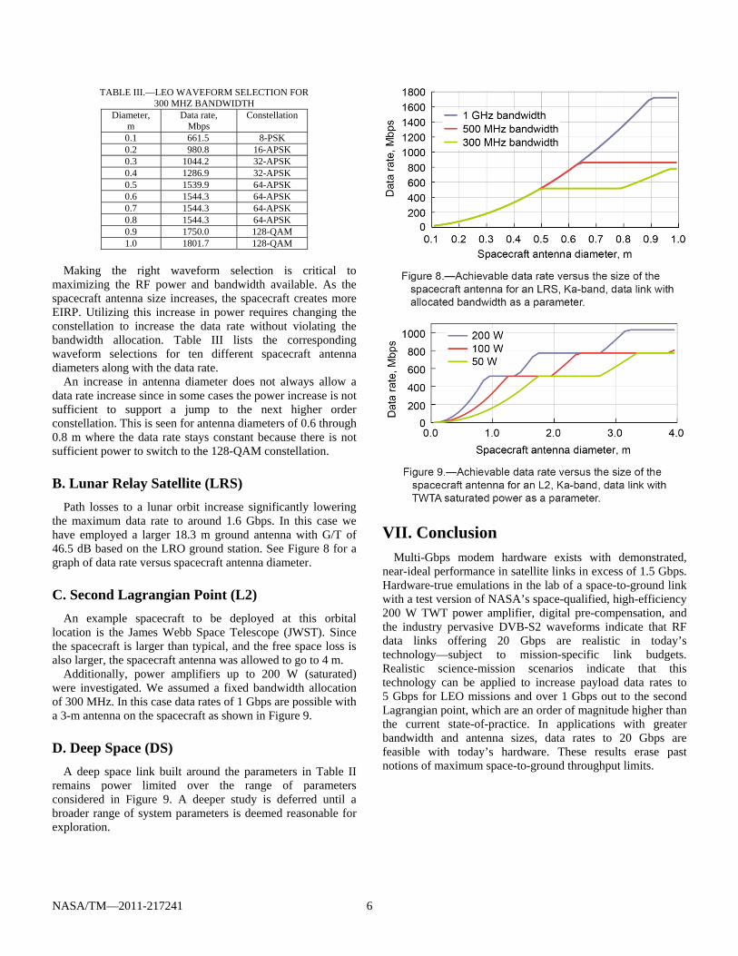
B. Lunar Relay Satellite (LRS)
Path losses to a lunar orbit increase significantly lowering the maximum data rate to around 1.6 Gbps. In this case we have employed a larger 18.3 m ground antenna with G/T of 46.5 dB based on the LRO ground station. See Figure 8 for a graph of data rate versus spacecraft antenna diameter.
C. Second Lagrangian Point (L2)
An example spacecraft to be deployed at this orbital location is the James Webb Space Telescope (JWST). Since the spacecraft is larger than typical, and the free space loss is also larger, the spacecraft antenna was allowed to go to 4 m.
Additionally, power amplifiers up to 200 W (saturated) were investigated. We assumed a fixed bandwidth allocation of 300 MHz. In this case data rates of 1 Gbps are possible with a 3-m antenna on the spacecraft as shown in Figure 9.
D. Deep Space (DS)
A deep space link built around the parameters in Table II remains power limited over the range of parameters considered in Figure 9. A deeper study is deferred until a broader range of system parameters is deemed reasonable for exploration.
VII. Conclusion Multi-Gbps modem hardware exists with demonstrated,
near-ideal performance in satellite links in excess of 1.5 Gbps. Hardware-true emulations in the lab of a space-to-ground link with a test version of NASA’s space-qualified, high-efficiency 200 W TWT power amplifier, digital pre-compensation, and the industry pervasive DVB-S2 waveforms indicate that RF data links offering 20 Gbps are realistic in today’s technology—subject to mission-specific link budgets. Realistic science-mission scenarios indicate that this technology can be applied to increase payload data rates to 5 Gbps for LEO missions and over 1 Gbps out to the second Lagrangian point, which are an order of magnitude higher than the current state-of-practice. In applications with greater bandwidth and antenna sizes, data rates to 20 Gbps are feasible with today’s hardware. These results erase past notions of maximum space-to-ground throughput limits.

NASA/TM—2011-217241 7
References
1. J. Schier, Space Communications and Navigation (SCaN) Integrated Network Architecture Definition Document (ADD) Volume 1: Executive Summary, January 2010, NASA Headquarters, Washington, D.C.
2. K. Tasaki, Y. Wong, F. Hartman, B. Blevins, D. Morales, J. Wesdock, L. Tran, and D. Zillig, “TDRSS K-Band Ultra Data Rate Demonstration,” (AIAA-2008-3470), SpaceOps 2008 Conference, Heidelberg, Germany, May 12-16, 2008.
3. W.K. McIntire, J.Y. Sun, D.G. Landon, J.S. Winn, J.L. Metz, F.J. Smith, E. Kneller, F.W. Gams, and L. Moore, “Ultra High Data Rate TDRSS K-Band SAR Demonstration Report,” L-3 Communications, Communication Systems – West, prepared in cooperation with NASA, June 30, 2010, L-3 Communications, Salt Lake City, UT 84116.
4. Earth Science and Applications from Space: National Imperatives for the Next Decade and Beyond, Division on Engineering and Physical Sciences, National Research Council, The National Academies Press, Washington, D.C., 2007.
5. New Worlds, New Horizons in Astronomy and Astrophysics, Division on Engineering and Physical Sciences, National Research Council, The National Academies Press, Washington, D.C., 2010.
6. G. Ungerboeck, “Channel Coding with Multilevel/Phase Signals,” IEEE Transactions on Information Theory, vol. IT-28, no. 1, pp. 55-67, Jan. 1982.
7. Digital Video Broadcasting (DVB); Second generation framing structure, channel coding and modulation systems for Broadcasting, Interactive Services, News Gathering and other broadband satellite applications, ETSI EN 302 307 V1.1.1 (2005-03), 650 Route des Lucioles, F-06921 Sophia Antipolis Cedex, FRANCE.
8. L. Giugno, M. Luise, and V. Lottici, “Adaptive Pre- and Post-compensation of Nonlinear Distortions for High-level Data Modulations,” IEEE Trans. Wireless Commun., vol. 3, no. 5, pp. 1490-1495, Sept 2004.
9. S. ten Brink and R. Mahadevappa, “Implementation Aspects of High-Speed Wireless LAN Systems,” Signals, Systems and Computers, 2004. Thirty-Eighth Asilomar Conf., vol. 1, pp. 789-793, Nov 7-10, 2004.
10. D. Landon, A. Laraway, and O. Haddadin, “A 4.5 Gbps Software Defined Radio,” MILCOM 2010, San Jose, CA, Oct 31–Nov 3, 2010 classified proceedings.
11. Space Network (SN) User Service Subsystem Re-placement (USSR) Systems Requirements Document, (452-SRD-USSR), NASA Goddard Space Flight Center, June 2009.
12. R. Pyndiah, “Near-optimum Decoding of Product Codes: Block Turbo Codes,” IEEE Trans. Commun., vol. 46, no. 8, pp. 1003-1010, Aug 1998.
13. R.N. Simons, J.D. Wilson, and D.A. Force, “High Power and Efficiency Space Traveling-Wave Tube Amplifiers with Reduced Size and Mass for NASA Missions,” 2008 IEEE MTT-S Inter. Microwave Symposium Digest, pp. 319-322, Atlanta, GA, June 15-20, 2008 (Also NASA/TM—2008-215220).
14. G. Marsaglia and W. Tsang, “The Ziggurat Method for Generating Random Variables,” Journal of Statistical Software, vol. 5, Issue 8, Oct 2000.
15. S. Shambayati, “Ka-Band Telemetry Operations Concept: A Statistical Approach,” Proceedings of the IEEE, vol. 95, no. 11, pp. 2171-2179, Nov 2007.

REPORT DOCUMENTATION PAGE Form Approved OMB No. 0704-0188
The public reporting burden for this collection of information is estimated to average 1 hour per response, including the time for reviewing instructions, searching existing data sources, gathering and maintaining the data needed, and completing and reviewing the collection of information. Send comments regarding this burden estimate or any other aspect of this collection of information, including suggestions for reducing this burden, to Department of Defense, Washington Headquarters Services, Directorate for Information Operations and Reports (0704-0188), 1215 Jefferson Davis Highway, Suite 1204, Arlington, VA 22202-4302. Respondents should be aware that notwithstanding any other provision of law, no person shall be subject to any penalty for failing to comply with a collection of information if it does not display a currently valid OMB control number. PLEASE DO NOT RETURN YOUR FORM TO THE ABOVE ADDRESS.
1. REPORT DATE (DD-MM-YYYY) 01-11-2011
2. REPORT TYPE Technical Memorandum
3. DATES COVERED (From - To)
4. TITLE AND SUBTITLE Peak Satellite-to-Earth Data Rates Derived From Measurements of a 20 Gbps Bread-Board Modem
5a. CONTRACT NUMBER
5b. GRANT NUMBER
5c. PROGRAM ELEMENT NUMBER
6. AUTHOR(S) Landon, David, G.; Simons, Rainee, N.; Wintucky, Edwin, G.; Sun, Jun, Y.; Winn, James, S.; Laraway, Stephen, A.; McIntire, William, K.; Metz, John, L.; Smith, Francis, J.
5d. PROJECT NUMBER
5e. TASK NUMBER
5f. WORK UNIT NUMBER WBS 432938.11.01.03.02.02.15
7. PERFORMING ORGANIZATION NAME(S) AND ADDRESS(ES) National Aeronautics and Space Administration John H. Glenn Research Center at Lewis Field Cleveland, Ohio 44135-3191
8. PERFORMING ORGANIZATION REPORT NUMBER E-17997
9. SPONSORING/MONITORING AGENCY NAME(S) AND ADDRESS(ES) National Aeronautics and Space Administration Washington, DC 20546-0001
10. SPONSORING/MONITOR'S ACRONYM(S) NASA
11. SPONSORING/MONITORING REPORT NUMBER NASA/TM-2011-217241
12. DISTRIBUTION/AVAILABILITY STATEMENT Unclassified-Unlimited Subject Category: 17 Available electronically at http://www.sti.nasa.gov This publication is available from the NASA Center for AeroSpace Information, 443-757-5802
13. SUPPLEMENTARY NOTES
14. ABSTRACT A prototype data link using a Ka-band space qualified, high efficiency 200 W TWT amplifier and a bread-board modem emulator were created to explore the feasibility of very high speed communications in satellite-to-earth applications. Experiments were conducted using a DVB-S2-like waveform with modifications to support up to 20 Gbps through the addition of 128-Quadrature Amplitude Modulation (QAM). Limited by the bandwidth of the amplifier, a constant peak symbol rate of 3.2 Giga-symbols/sec was selected and the modulation order was varied to explore what peak data rate might be supported by an RF link through this amplifier. Using 128-QAM, an implementation loss of 3 dB was observed at 20 Gbps, and the loss decreased as data rate or bandwidth were reduced. Building on this measured data, realistic link budget calculations were completed. Low-Earth orbit (LEO) missions based on this TWTA with reasonable hardware assumptions and antenna sizing are found to be bandwidth-limited, rather than power-limited, making the spectral efficiency of 9/10-rate encoded 128-QAM very attractive. Assuming a bandwidth allocation of 1 GHz, these computations indicate that low-Earth orbit vehicles could achieve data rates up to 5 Gbps-an order of magnitude beyond the current state-of-practice, yet still within the processing power of a current FPGA-based software-defined modem. The measured performance results and a description of the experimental setup are presented to support these conclusions. 15. SUBJECT TERMS Traveling-wave tube amplifier; Software defined modem; Software defined radio; High order modulation; Turbo product code; DVB-S2; Low density parity check; PSK; APSK; QAM; Space communications and navigation
16. SECURITY CLASSIFICATION OF: 17. LIMITATION OF ABSTRACT UU
18. NUMBER OF PAGES
13
19a. NAME OF RESPONSIBLE PERSON STI Help Desk (email:[email protected])
a. REPORT U
b. ABSTRACT U
c. THIS PAGE U
19b. TELEPHONE NUMBER (include area code) 443-757-5802
Standard Form 298 (Rev. 8-98)Prescribed by ANSI Std. Z39-18

