pedal operated water pumping system
DESCRIPTION
PEDAL OPERATED WATER PUMPING SYSTEMTRANSCRIPT

PEDAL OPERATED WATER PUMPING SYSTEM
SYNOPSIS
Water plays an important role in the material, social and cultural life of man
kind. The water needs are increasing day by day. This is the result of population growth
and increase in the standard of living which is directly proportional to water
consumption.
The lifting of water for drinking or irrigation purposes is of great importance in
widely distributed villages with little or no rural electrification and where under ground
water is available.

INTRODUCTION
The aim of the project is Pedal operated water pumping system. Radial plunger
Pedal operated reciprocating water pumping system are reciprocating pump in which the
piston is provided for the pumping action. The piston is reciprocated with the help of a
pneumatic cylinder, pedal with chain sprocket mechanism and Cam mechanism.
A pump is a Mechanical device which converts mechanical energy into hydraulic
energy. This pump is classified into two types;
i. Positive Displacement and
ii. Non-Positive Displacement pump
In positive displacement pump is the one, in which the liquid is transferred
positively from one stage to another stage by the to and fro motion of the plunger or
piston of the pump.
In non-positive displacement pump the liquid is transferred by the centrifugal
force. This force is cause due to the rotary movement of an impeller. In this, our project,
pedal operated reciprocating water pump is of positive displacement pump. The salient
features of a pedal operated reciprocating water pump have been retained in our project
model and this has been achieved with great care.
Due to high precision work involved in producing pedal operated reciprocating
water pump besides higher cost these pumps are not widely manufactured by most of the
industries. The very name itself indicates that it works with the help of a piston. This
piston is reciprocated with the help of a solenoid valve and electronic timing control unit.
LITERATURE SURVEY

PNEUMATICS
The word ‘pneuma’ comes from Greek and means breather wind. The word
pneumatics is the study of air movement and its phenomena is derived from the word
pneuma. Today pneumatics is mainly understood to means the application of air as a
working medium in industry especially the driving and controlling of machines and
equipment.
Pneumatics has for some considerable time between used for carrying out the
simplest mechanical tasks in more recent times has played a more important role in the
development of pneumatic technology for automation.
Pneumatic systems operate on a supply of compressed air which must be made
available in sufficient quantity and at a pressure to suit the capacity of the system. When
the pneumatic system is being adopted for the first time, however it wills indeed the
necessary to deal with the question of compressed air supply.
The key part of any facility for supply of compressed air is by means using
reciprocating compressor. A compressor is a machine that takes in air, gas at a certain
pressure and delivered the air at a high pressure.

Compressor capacity is the actual quantity of air compressed and delivered and the
volume expressed is that of the air at intake conditions namely at atmosphere pressure
and normal ambient temperature.
The compressibility of the air was first investigated by Robert Boyle in 1962 and
that found that the product of pressure and volume of a particular quantity of gas.
The usual written as
PV = C (or) PıVı = P2V2
In this equation the pressure is the absolute pressured which for free is about 14.7
Psi and is of courage capable of maintaining a column of mercury, nearly 30 inches high
in an ordinary barometer. Any gas can be used in pneumatic system but air is the mostly
used system now a days.
SELECTION OF PNEUMATICS

Mechanization is broadly defined as the replacement of manual effort by
mechanical power. Pneumatic is an attractive medium for low cost mechanization
particularly for sequential (or) repetitive operations. Many factories and plants already
have a compressed air system, which is capable of providing the power (or) energy
requirements and the control system (although equally pneumatic control systems may be
economic and can be advantageously applied to other forms of power).
The main advantage of an all pneumatic system are usually economic and
simplicity the latter reducing maintenance to a low level. It can also have out standing
advantages in terms of safety.
PRODUCTION OF COMPRESSED AIR
Pneumatic systems operate on a supply of compressed air, which must be made
available. In sufficient quantity and at a pressure to suit the capacity of the system. When
pneumatic system is being adopted for the first time, however it wills indeed the
necessary to deal with the question of compressed air supply.
The key part of any facility for supply of compressed air is by means using
reciprocating compressor. A compressor is a machine that takes in air, gas at a certain
pressure and delivered the air at a high pressure.
Compressor capacity is the actual quantity of air compressed and delivered and the
volume expressed is that of the air at intake conditions namely at atmosphere pressure
and normal ambient temperature. Clean condition of the suction air is one of the factors,
which decides the life of a compressor. Warm and moist suction air will result in
increased precipitation of condense from the compressed air. Compressor may be
classified in two general types.
1. Positive displacement compressor.
2. Turbo compressor
Positive displacement compressors are most frequently employed for
compressed air plant and have proved highly successful and supply air for pneumatic
control application.
The types of positive compressor
1. Reciprocating type compressor
2. Rotary type compressor

Turbo compressors are employed where large capacity of air required at low
discharge pressures. They cannot attain pressure necessary for pneumatic control
application unless built in multistage designs and are seldom encountered in
pneumatic service.
RECIPROCATING COMPRESSORS
Built for either stationary (or) portable service the reciprocating compressor is by
far the most common type. Reciprocating compressors lap be had is sizes from the
smallest capacities to deliver more than 500 m³/min. In single stage compressor, the air
pressure may be of 6 bar machines discharge of pressure is up to 15 bars. Discharge
pressure in the range of 250 bars can be obtained with high pressure reciprocating
compressors that of three & four stages.
Single stage and 1200 stage models are particularly suitable for pneumatic
applications , with preference going to the two stage design as soon as the discharge
pressure exceeds 6 bar , because it in capable of matching the performance of single stage
machine at lower costs per driving powers in the range .

COMPONENTS AND DESCRIPTION
Pneumatic cylinder
An air cylinder is an operative device in which the state input energy of
compressed air i.e. pneumatic power is converted in to mechanical output power, by
reducing the pressure of the air to that of the atmosphere.
Single acting cylinder
Single acting cylinder is only capable of performing an operating medium in only
one direction. Single acting cylinders equipped with one inlet for the operating air
pressure, can be production in several fundamentally different designs.
Single cylinders develop power in one direction only. Therefore no heavy
control equipment should be attached to them, which requires to be moved on the piston
return stoke single action cylinder requires only about half the air volume consumed by a
double acting for one operating cycle.
Double acting cylinders:

A double acting cylinder is employed in control systems with the full
pneumatic cushioning and it is essential when the cylinder itself is required to retard
heavy messes. This can only be done at the end positions of the piston stock. In all
intermediate position a separate externally mounted cushioning derive most be provided
with the damping feature.
The normal escape of air is out off by a cushioning piston before the end of the stock
is required. As a result the sit in the cushioning chamber is again compressed since it
cannot escape but slowly according to the setting made on reverses. The air freely enters
the cylinder and the piston stokes in the other direction at full force and velocity.
4.4.1. Parts of Pneumatic Cylinder
Piston
The piston is a cylindrical member of certain length which reciprocates inside the
cylinder. The diameter of the piston is slightly less than that of the cylinder bore
diameter and it is fitted to the top of the piston rod. It is one of the important part which
converts the pressure energy into mechanical power.
The piston is equipped with a ring suitably proportioned and it is relatively soft
rubber which is capable of providing good sealing with low friction at the operating
pressure. The purpose of piston is to provide means of conveying the pressure of air
inside the cylinder to the piston of the oil cylinder.
Generally piston is made up of
Aluminium alloy-light and medium work.
Brass or bronze or CI-Heavy duty.
The piston is double acting type. The piston moves forward when the high-
pressure air is turned from the right side of cylinder. The piston moves backward when
high pressure acts on the piston from the left side of the cylinder. The piston should be as
strong and rigid as possible.
The efficiency and economy of the machine primarily depends on the working of
the piston. It must operate in the cylinder with a minimum of friction and should be able
to withstand the high compressor force developed in the cylinder and also the shock load
during operation.

The piston should posses the following qualities.
a. The movement of the piston not creates much noise.
b. It should be frictionless.
c. It should withstand high pressure.
Piston Rod
The piston rod is circular in cross section. It connects piston with piston of other
cylinder. The piston rod is made of mild steel ground and polished. A high finish is
essential on the outer rod surface to minimize wear on the rod seals. The piston rod is
connected to the piston by mechanical fastening. The piston and the piston rod can be
separated if necessary.
One end of the piston rod is connected to the bottom of the piston. The other end
of the piston rod is connected to the other piston rod by means of coupling. The piston
transmits the working force to the oil cylinder through the piston rod. The piston rod is
designed to withstand the high compressive force. It should avoid bending and withstand
shock loads caused by the cutting force. The piston moves inside the rod seal fixed in the
bottom cover plate of the cylinder. The sealing arrangements prevent the leakage of air
from the bottom of the cylinder while the rod reciprocates through it.

Cylinder Cover Plates
The cylinder should be enclosed to get the applied pressure from the compressor
and act on the pinion. The cylinder is thus closed by the cover plates on both the ends
such that there is no leakage of air. An inlet port is provided on the top cover plate and
an outlet ports on the bottom cover plate. There is also a hole drilled for the movement
of the piston.
The cylinder cover plate protects the cylinder from dust and other particle and
maintains the same pressure that is taken from the compressor. The flange has to hold
the piston in both of its extreme positions. The piston hits the top plat during the return
stroke and hits the bottom plate during end of forward stroke. So the cover plates must
be strong enough to withstand the load.
Cylinder Mounting Plates:
It is attached to the cylinder cover plates and also to the carriage with the help of
‘L’ bends and bolts.

SPRACKET AND CHAIN DRIVE MECHANISM:-
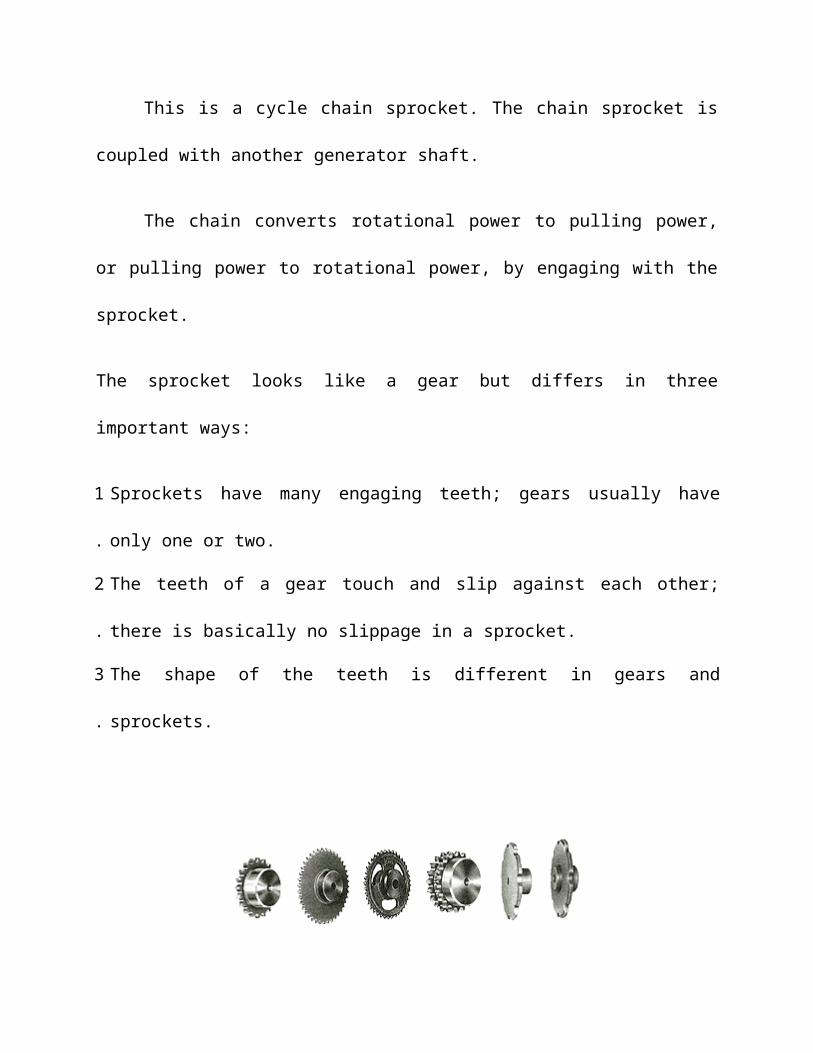
This is a cycle chain sprocket. The chain sprocket is coupled with another
generator shaft.
The chain converts rotational power to pulling power, or pulling power to
rotational power, by engaging with the sprocket.
The sprocket looks like a gear but differs in three important ways:
1. Sprockets have many engaging teeth; gears usually have only one or two.
2. The teeth of a gear touch and slip against each other; there is basically no slippage in a
sprocket.
3. The shape of the teeth is different in gears and sprockets.
Figure Types of Sprockets

HOUSE AND FITINGS:
It is provided for the passage of compressed air from the compressor outlet to the
operating valve.
Two separate pipes also connect the operating valve with the working cylinder
pressure drop through and air line depends on the flow rate, pipe diameter, pipe length
and pipe geometry. It can be determined directly for straight pipes of any given length.
A small chaining bore size can have marked effect on pressure drop, where as even
doubling the pipe length, will only result in doubling the pressure drop.
Pressure drop through bends and fittings can only be determined by empirical
tests, since it is specific to the internal geometry involved. Rigid pipes however are less
manipulated through remain form of bends with arrangements increase and variable air
have to flow and the flow itself may be of fluctuating or pulsating nature. In this case it
is thus normally based on practical recommendation.
SEALS:
Seal is an important component of a pneumatic system and is used to prevent the
air leakage through the joint.

This project passes the static seal which are used to prevent the leakage through
the stationary surface.
Material of the seal is Teflon tape. Teflon has the following properties
Withstand the system pressure and temperature without any damage.
Resist the wear and abrasion.
Recover from deformation.
Resists the adverse effects such as deterioration and shrinking
caused by the system air.
Seals are devices for closing gaps to prevent leakage or make pressure joints and
also to prevent the entry of air and dirt from outside into the system. The material of seal
must be compatible with the fluid medium. It is a circular ring made of synthetic rubber.
It is used for providing tight sealing between the piston and the cylinder wall. It prevents
air leakage from the top and bottom of the cylinder.
Seals for air cylinder and valves are not normally called upon to seal pressure
higher than about 2 bars. Since the fluid to be seated is a gas, (in our case air) rubbing
speeds tends to be high and the seal the seal may have to be operated under dry
conditions with minimal lubrication.

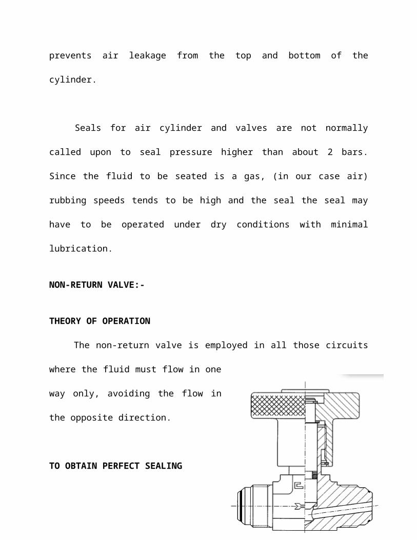
NON-RETURN VALVE:-
THEORY OF OPERATION
The non-return valve is employed in all those circuits where the fluid must flow in
one way only, avoiding the flow in the opposite direction.
TO OBTAIN PERFECT SEALING
1. Make sure that all tubes are perfectly clean
and that there are no impurities in the system
where the fluid will flow.
2. Remove protective caps only when ready to
assemble, making sure that in the assembly
phase no impurities enter the system.
TECHNICAL CHARACTERISTICS
1. The non-return valve assures a perfect tightness of the circuit, provided that the
indicated nominal working pressures are kept as recalled in this catalogue.
2. The particular profile of its inner elements assures the correct flow with a minimum
pressure drop.

3. The valve is a compact, particularly sturdy element; the seal is obtained by a plain seat
metal to metal plug with an electrometric seal gasket assuring tightness at low working
pressures.
4. A basic body allows to interchange different types of non return valves applying from
time to time the different engaged stud ends as chosen by the customer allowing an easy
logistic of the stock.
5. The valve may be used for convoying mineral oils, fuels, compressed air or gases.
6. The nominal working temperature is between –20° and +120° Celsius degrees for
carbon steel, and between –60° and +200° Celsius degrees for stainless steel. The limit
may change according to the type of gasket used.
COMPONENT TESTING
Valves are checked for leakages at low
pressure and at high pressure (nominal
working pressures plus 33%).
SAFETY FACTORS
Safety factor is 2.5:1 at static load with temperature within range.
FINISH TREATMENT
All valves are treated with a chemical polishing with steel spheres which eliminate
all oxides and burrs due to the machining phase, without altering or damaging the
product. All valves are plugged to avoid internal damages.

DESIGN OF EQUIPMENT AND DRAWING
Pneumatic components and its specification
The pneumatic cutting and Filing machine consists of the following components to
full fill the requirements of complete operation of the machine.
1. Double acting pneumatic cylinder
2. Connectors
3. Hoses
1. Double acting pneumatic cylinder
Technical Data
Stroke length : Cylinder stoker length 160 mm = 0.16 m
Piston rod : 18 mm = 18 x 10ˉ³ m
Quantity : 2
Seals : Nitride (Buna-N) Elastomer
End cones : Cast iron
Piston : EN – 8
Media : Air
Temperature : 0-80 º C
Pressure Range : 8 N/m²
2. Connectors
Technical data
Max working pressure : 10 x 10 ⁵ N/m²
Temperature : 0-100 º C
Fluid media : Air
Material : Brass
3. Hoses
Technical date
Max pressure : 10 x 10 ⁵ N/m²
Outer diameter : 6 mm = 6 x 10 ˉ ³m
Inner diameter : 3.5 mm = 3.5 x 10 ˉ ³m
DESIGN CALCULATION
PNEUMATIC CYLINDER:

Design of Piston rod:
Load due to air Pressure.
Diameter of the Piston (d) = 40 mm
Pressure acting (p) = 6 kgf/cm²
Material used for rod = C 45
Yield stress (σy) = 36 kgf/mm²
Assuming factor of safety = 2
Force acting on the rod (P) = Pressure x Area
= p x (Πd² / 4)
= 6 x {( Π x 4² ) / 4 }
P = 73.36 Kgf
Design Stress(σy) = σy / F0 S
= 36 / 2 = 8 Kgf/mm²
= P / (Π d² / 4 )
∴ d = √ 4 p / Π [ σy ]
= √ 4 x 75.36 / {Π x 18}
= √ 5.33 = 2.3 mm

∴ Minimum diameter required for the load = 2.3 mm
We assume diameter of the rod = 15 mm
DISTRIBUTION CHAMBER:
Design of cylinder thickness:
Material used = Cast iron
Assuming internal diameter of the cylinder = 75 mm
Ultimate tensile stress = 250 N/mm² = 2500 gf/mm²
Working Stress = Ultimate tensile stress / factor of safety
Assuming factor of safety = 4
Working stress ( ft ) = 2500 / 4 = 625 Kgf/cm²
According to ‘LAMES EQUATION’
Minimum thickness of cylinder ( t ) = ri {√ (ft + p) / (ft – p ) -1 }
Where,
ri = inner radius of cylinder in cm.
ft = Working stress (Kgf/cm²)
p = Working pressure in Kgf/cm²

∴ Substituting values we get,
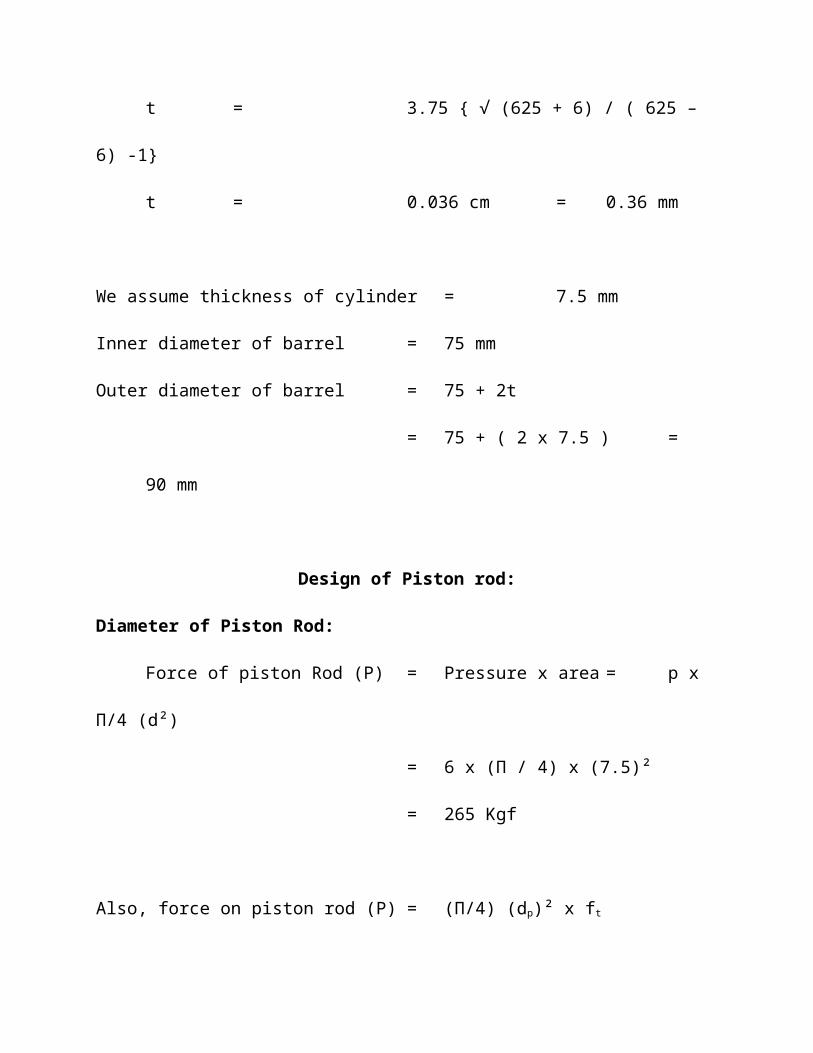
t = 3.75 { √ (625 + 6) / ( 625 – 6) -1}
t = 0.036 cm = 0.36 mm
We assume thickness of cylinder = 7.5 mm
Inner diameter of barrel = 75 mm
Outer diameter of barrel = 75 + 2t
= 75 + ( 2 x 7.5 ) = 90 mm
Design of Piston rod:
Diameter of Piston Rod:
Force of piston Rod (P) = Pressure x area = p x Π/4 (d²)
= 6 x (Π / 4) x (7.5)²
= 265 Kgf
Also, force on piston rod (P) = (Π/4) (dp)² x ft
P = (Π/4) x (dp)² x 625
256 = (Π/4) x (dp)² x 625
∴ dp² = 256 x (4/Π) x (1/625)
= 0.52
dp = 1.87 cm = 18.7 mm
By standardizing dp = 20 mm
Length of piston rod:
Approach stroke = 50 mm
Length of threads = 2 x 20 = 40mm
Extra length due to front cover = 12 mm
Extra length of accommodate head = 20 mm
Total length of the piston rod = 50 + 40 + 12 + 20
= 12.2 cm
By standardizing, length of the piston rod = 120 mm


WORKING PRINCIPLE
Initially starting with cycle pedaling operation is manually. The sprocket is
coupled to another sprocket with the help of chain drive. The second sprocket shaft is
coupled to the Cam plate with the help of End bearings. The Cam plate is coupled to the
pneumatic cylinder with the help of Cam shaft
The 2 outlet ports are connected to an actuator (Cylinder). The pneumatic
activates is a double acting, single rod cylinder. The cylinder output is coupled to further
purpose. The piston end has a water horning effect to prevent sudden thrust at extreme
ends. The end of the cylinder two Non return valve is connected for both of the side. One
Non return valve for suction side and another one non return valve are for delivery side.
The pedaling operation done by manually with the help of man and this power is
transferred to the Cam mechanism. This Cam and cam shaft is used to activate the
pneumatic cylinder. The pneumatic cylinder forward stroke is suction the water and
return stroke will deliver the water.

FABRICATION
COMPONENTS:
Piston
Actuating rod
Base Plate
Bush
Flexible hoses
Cylinder block
Piston:
The piston is fitted in the cylinder block and reciprocates inside. When the
solenoid valve supplies the air in the front end of the piston, the piston is pushed forward.
This moves the hacksaw and the cutting stroke takes place.
Then the solenoid valve supplies air to the rear end of the piston. The pressure is
same but the contact area is less due to the presence of the piston rod and pushes the
piston at a greater pressure thus resulting in a fast return stroke. The material for the
piston is Aluminum.
Actuating Rod:

The actuating rod is fitted inside the bush. It is connected at one end to the piston
rod and at the other end it is connected to the hacksaw frame. It reciprocates inside the
bush. The material for the actuating rod is mild steel.
Base Plate:
All the components of the machine are mounted on the base plate. It withstands
the vibrations encountered during machining. It is mounted on the bench.
Flexible Hose:
The flexible hoses connect the solenoid valve and the cylinder block. Hoses are
made of in layer of elastomer (or) synthetic rubber and braided fabric which takes up the
higher pressure. If the hose is subjected to rubbing, it should be enclosed in a protective
sleeve.
Cylinder block:

The cylinder block has two opening for admitting air inside the block for
achieving the reciprocation motion of the piston. The material for cylinder block is
Aluminium.
Bush:
It is cylindrical in shape with a central hole. It supports the actuating rod. The
actuating rod reciprocates in the bore at the bush. The material for the bush is mild steel.
APPLICATIONS

Since the Pedal operated reciprocating water Pump is more efficient it is used for
pumping the water or oil mostly.
Domestic Applications
Industrial Applications
It is widely applicable in industrial practices. It is used,
1. In hydraulic lifts and Jacks
2. In hydraulic press
3. In load transfer applications
4. In hydraulic puller
5. In service centers
6. In mechanical clamping applications
7. In deep drawing, shearing etc
8. In machine shops for actuating various machines
9. In wheel mechanism of an aero crafts
And it is used in all places wherever positive displacement is required. There it
has a wide range of application in all fields.
NEED FOR AUTOMATION

Nowadays almost all the manufacturing process is being atomized in order to
deliver the products at a faster rate. The manufacturing operation is being atomized for
the following reasons.
To achieve mass production
To reduce man power
To increase the efficiency of the plant
To reduce the work load
To reduce the production cost
To reduce the production time
To reduce the material handling
To reduce the fatigue of workers
To achieve good product quality
Less Maintenance
ADVANTAGES AND LIMITATIONS
ADVANTAGES:
Even if all the other pumps are similar in use the Pedal operated reciprocating
water pump is more advantageous than the other pumps.

1. This is of compact in size
2. Less Maintenance is enough
3. The oil or water pumped is of higher pressure
4. Quite running and smooth operation is achieved.
5. Higher efficiency
6. Full efficient positive displacement pump
7. Effective working principle
8. It does not have any Prime mover, like electric motor related to
the unit.
9. As the air is freely available, we can utilize the air to pumping
the water and hence it is economical.
10. Less Maintenance
LIMITATIONS
It is costlier than the other types of pump because of compressor unit.
Less efficiency when compressed to other device.
Leakage of air affects the working of the unit.