pediatric breathing simulator - ultimaker: 3d printers · user manual anakin model . 1 1.0 ... from...
TRANSCRIPT

Pediatric Breathing
Simulator
User Manual
Anakin Model

1
1.0 Quick Start
Congratulations on purchasing your very own pediatric breathing simulator. Your device, Anakin, is a
part task respiratory simulator. This device allows for the simulation of a variety of respiratory patterns
including but not limited to: Normal breathing, seesaw breathing, respiratory distress and collapsed
lungs. This quickstart guide is used once the device has been assembled. Follow the steps below to use
your device.
1. Charge Air compressor to full
a. If you are using an external air system, this step can be ignored
2. Plug in and turn on Power supply, set to 12V
3. Plug in myDAQ device and launch LabVIEW program
4. Connect air supply to manikin via tubing ¼ “ coupler plug - you should hear a ‘click’ when
properly inserted
a. Ensure that the pressure regulator knob is turned down to prevent premature inflation
5. In LabVIEW Virtual Instrument (VI) (Figure 1) Select the arrow (left) to run the VI
6. Once VI is running, slowly turn the pressure regulation valve until air begins to flow into the
system and the desired pressure is reached
a. The system is now in normal breathing mode and will remain in this setting until the
user adjusts the mode
7. To change the breathing pattern, select from the drop down menu located on the front panel
(Figure 2)

2
8. From the front panel, two methods of adjustment of breathing pattern can be found; manual
manipulation of breathing characteristics and selecting from preset conditions. Both mode of
operation require selection of the prefered method of operation from the drop down menu.
9. A simulation can be run for the desired amount of time, and revert back to normal breathing by
turning the lever labeled

3
2.0 Table of contents
1.0 Quick Start ............................................................................................... pg. 1-2
2.0 Table of contents ........................................................................................ pg. 3
3.0 Background information............................................................................. pg. 4
4.0 Components............................................................................................. pg. 5-7
5.0 Setup ...................................................................................................... pg. 8-10
6.0 Maintenance ............................................................................................ pg. 11
7.0 Glossary of Technical Terms .................................................................... pg. 12
8.0 Troubleshooting ....................................................................................... pg. 13

4
3.0 Background information Anakin is a pneumatic respiratory simulator capable of simulating a wide variety of respiratory situations,
while accounting for physiologically realistic lung and diaphragm movements. The device is comprised of
four major components:
1. A combination of two 3D printed ‘lung’ compartments and a 3D printed ‘diaphragm’
compartment, each with an elastic overlay to provide elasticity and resistance during breathing.
2. A system of solenoid pinch valves which open and close as programmed
(synchronously, but independent of each other). When activated with short pulses of 12 volts,
pinch valves open or close to allow air to flow throughout each compartment independently.
3. An air compressor, which distributes compressed air throughout the system with pressure
controlled by a regulator.
4. A custom LabVIEW program and interface, coupled with solenoid control boards. The control
boards distribute the necessary amount of voltage to the solenoid valves from an external
power supply, and the LabVIEW program allows the user to manipulate the pressure at which air
is distributed through the system (via the regulator) and the rate of the valves opening/closing
(to constitute varying respiratory conditions). The LabVIEW user interface allows for the user to
select from a drop-down menu of preset conditions or build their own desired situation, and
easily activate the system with start/stop buttons. The range of respiratory characteristics
includes breathing rates from 5-200 breaths per minute and inhalation/exhalation durations
from 0.3-12 seconds.

5
4.0 Components
1. Air compressor
2. Pressure Regulator
3. Pressure Gauge
4. Pressure Fittings Misc.
5. 8’ length of tubing
6. Four way barb ¼” barb
6
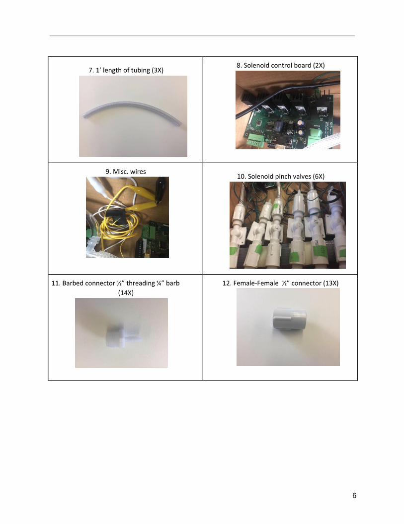
7. 1’ length of tubing (3X)
8. Solenoid control board (2X)
9. Misc. wires
10. Solenoid pinch valves (6X)
11. Barbed connector ½” threading ¼” barb
(14X)
12. Female-Female ½” connector (13X)

7
13. 5’ length of tubing (6X)
14. Right lung compartment, clamp and elastic membrane
15. Left lung compartment, clamp and elastic membrane
16. Diaphragm compartment, clamp and elastic membrane
17. Manikin Shell
18. Latex ‘Skin’

8
19. Silicone ‘Skin’
20. Power Supply
21. Housing for solenoids and control boards

9
5.0 Setup Once all components have been accounted for follow the steps below to assemble your manikin.
5.1 The computer
1. For the computer you will need to take the two solenoid control valves, the myDAQ and the 6
solenoid valves.
2. Label the valves 1-6 and lay them within the housing so that each valve has one spiket facing
outside of the housing.
3. Once they are labeled take the first solenoid control panel. On one side you will notice inlets
labeled 0-4. You want to plug valves 1-5 into these ports in sequential order.
(valve 1 plugs into port 0, valve 2 plugs into port 1, etc.).
4. Once you have successfully plugged in the first control board, take the second board and plug
the last valve (valve 6) into port 0).
5. Within the box lay the two boards next to each other. On the opposite side of the ports you will
notice both boards have positive and negative connections. Wire the two positive terminals
together on the boards using alligator clips, do the same for the negative ports.
6. Once you have connected the terminals together you will need to add another alligator clip to
the positive and negative terminals, these will run out of the housing and connect to a power
source of 12v.
7. Next you will need to connect the boards to the mydaq. Below the positive and negative
terminals on the board there are outlet terminals labeled R+,
R1,R2,R3,R4,R5,R-. These are the outlet ports for the inlet terminals on the boards.
8. The outlet ports should be wired to the corresponding ports on the mydaq. For example R1
should be wired to line port 1 on the mydaq and so on. Once all the outlets are wired to the daq.
Take the second solenoid control board, and wire R1 on that board to line port 6 on the daq.
9. Make sure that the mydaq ground port is connected to the ground line of the other two
solenoid boards.
10. Once all of these steps are complete, plug in the mydaq cord to the side of the mydaq, this
should run outside of the housing and plug into the computer.
11. The last step inside the housing is to plug the inlet valves together. Take valve 1, 3, and 5 and
place the small 1’ long tubing on the end so that the tube is inside the housing unit. Use the 4-
way connector and connect the tubes from 1, 3, and 5 that are in the housing unit into the 4 way
connector. Then take the 5’ tubing and plug it into the last port on the 4-way connector. This will
run out of the housing and be the air inlet valve.
5.2 The device
1. Take the 5’ lengths of tubing and the inflatable compartments
2. Using some force, place each one of the tubes into the backs of the lungs, and diaphragm.

10
3. Make sure to keep track of which tube is which. The right lung should have tubes 1 and 2, left
lung tubes 3 and 4 and the diaphragm should have tubes 5 and 6.
4. Within the box
5. Once you have made sure that the tubes are securely fastened into the inflatable components,
plug the tubes into their corresponding solenoid valves. The solenoid valves will be labeled 1-6
and their plug in point will be on the side of the box.
6. To assemble pressure regulator take pressure regulator piece (already attached to male air
coupler/ component 2) female end and attach to component 4 male end. On The outlet hole
going up attach the pressure valve (component 3). Once connected on other mael end attach ¼”
→ ½ ” F-F connector (pictured with component 4). A final step is to take on the the barbed
connectors (component 11) and screw in and push on tubing going into four way connector
7. Take the pressure regulator component and plug it into the air compressor until you hear it click.
8. Make sure the regulator is turned all the way to the left before you refill the air compressor
tank.
9. Once the pressure regulator is plugged into the air compressor, plug the other end into the 5’
tube that is connected to the valves inside the housing complex.
10. Once you have completed these steps your product is ready to use!
5.3 Running the program
1. Launch LabVIEW and open up Breathing Simulation VI.
2. Select from the drop-down menu of preset respiratory conditions and choose the desired
situation to simulate.
3. Within these preset conditions, the user has the ability to manipulate breaths per minute,
inhalation duration, exhalation duration, tidal volume and lung/diaphragm rise.
4. The condition and respiratory characteristics can be altered before or during a simulation, and
the manikin can go back to “Normal breathing” at anytime by the flick of the “Back to Normal
breathing” switch.

11
5.4 Device Schematic

12
6.0 Maintenance In order to ensure that the respiratory manikin remains in functioning order the following steps must be
taken at periodic intervals
1. To maintain realistic skin conditions baby powder should be applied to the silicone skin layer,
this keeps the skin pliable as well as prevents stickiness
2. The left, right and diaphragm compartments need to be tightened after prolonged use to ensure
that the inflation is at the proper amplitudes
3. After membrane for the left, right and diaphragm compartments should also be changed
periodically to prevent unnecessary wear and potential rupture
4. The power supply if not running should be powered down to prevent excess heating of
solenoids as well as to prolong functionality of power supply
5. The connection points at the base of the lungs needs to be checked to prevent leaking and poor
quality of simulation
13
7.0 Glossary of Technical Terms Pneumatic - Relating, containing or operating by gas under pressure.
Solenoid valve - Electromagnetically bimodal activated valve. Valve pinches or opens with respect to
short bursts of required voltage
Regulator - Control valve that steps down and regulates input pressure of fluid or gas, reaching a
desired value as the output pressure
LabVIEW - ‘Laboratory Virtual Instrument Engineering Workbench’. Block based visual programming
interface used for data acquisition, instrument control and industrial automation on a variety of
operating systems.
myDAQ - Portable measurement and instrumentation device used to communicate and
transmit LabVIEW program to electrical device.

14
8.0 Troubleshooting Valves not responsive
● Check indication LEDs
● Reset power supply
● Re-wire terminals to ensure proper connections
Improper lung/diaphragm movement
● Listen for air leak, locate source
● Check tubing connections
● Remove elastic overlap and re-clamp to 3D printed compartment