peds: a parallel error detection scheme for tcam devices author: anat bremler-barr, david hay, danny...
TRANSCRIPT

PEDS: A PARALLEL ERROR DETECTION SCHEME FOR TCAM DEVICES
Author: Anat Bremler-Barr, David Hay, Danny Hendler and Ron M. Roth
Publisher/Conf.: IEEE INFOCOM 2009
Speaker: Han-Jhen Guo
Date: 2009.03.25
1

OUTLINE
Introduction The Proposed Scheme
Basic idea PEDS architecture Hardware design (with mod-2 counters)
Performance
2
INTRODUCTION
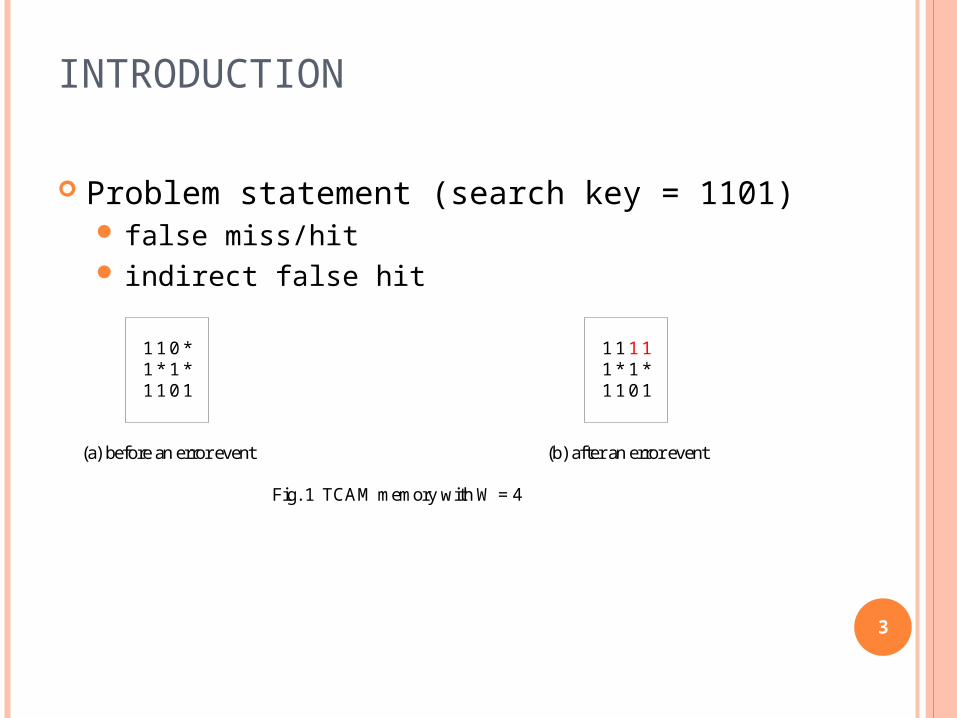
Problem statement (search key = 1101) false miss/hit indirect false hit
3
Fig. 1 TCAM memory with W = 4
1 1 0 *1 * 1 *1 1 0 1
(a) before an error event
1 1 1 11 * 1 *1 1 0 1
(b) after an error event

The Proposed Scheme- Basic idea
Assume that only one error can occur in each pair of symbols
For each clause in the TCAM memory (eg. 0*10)1. encoding to a pair with the check bit(s)
eg. 00**1100
2. applying a sequence of TCAM searches for a predetermined set of search keys
eg. predetermined set = {*…*01*…*, *…*10*…*})
3. analyzing their results from step 2. there occurs 2 matches → no error (** is matched) there occurs no match → no error (00 or 11 is
matched) there occurs 1 match only → ERROR!
4

The Proposed Scheme - Basic idea
eg. check entry = *10*
5
** 11 00 **
01 ** ** ** (m)
10 ** ** ** (m)
** 11 00 **
** 01 ** ** (n)
** 10 ** ** (n)
** 11 00 **
** ** 01 ** (n)
** ** 10 ** (n)
** 11 00 **
** ** ** 01 (m)
** ** ** 10 (m)

The Proposed Scheme - Basic idea
eg. check entry = *10* with errors
6
** 11 01 0*
01 ** ** ** (m)
10 ** ** ** (m)
** 11 01 0*
** 01 ** ** (n)
** 10 ** ** (n)
** 11 01 0*
** ** 01 ** (m)
** ** 10 ** (n)
** 11 01 0*
** ** ** 01 (m)
** ** ** 10 (n)
ERROR!
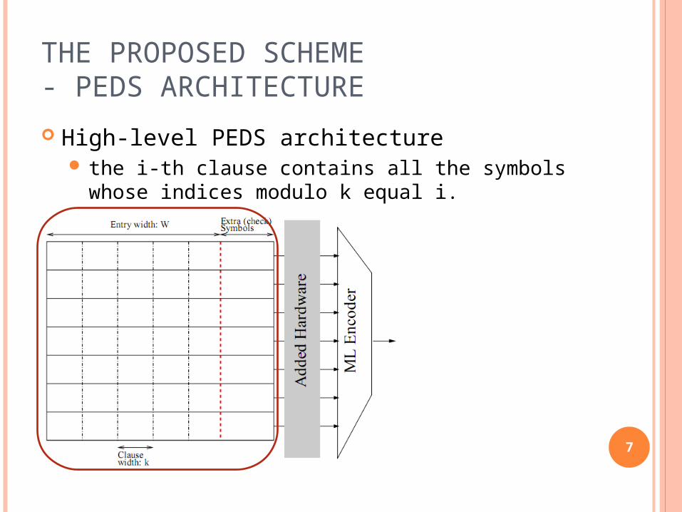
THE PROPOSED SCHEME- PEDS ARCHITECTURE
High-level PEDS architecture the i-th clause contains all the symbols whose
indices modulo k equal i.
7

THE PROPOSED SCHEME- PEDS ARCHITECTURE
(eg. of TCAM memory)
check each of the W/k clauses (in conjunction with its check symbols) separately—but concurrently for all entries—against a predetermined set of search keys
8
Fig. 3 High-level PEDS architecture from fig. 1 (W = 4, if k = 2)
(a) original TCAM memory
11
1*
11
0*
01
1*
1 2 3 4
(b) after interleaving
10
11
10
1*
11
**
1
2
3 4
1clause
2Extra Extra
(c) compute check symbols
10
11
10
1*
11
**
101*
11**
1011
21
Extra
clause
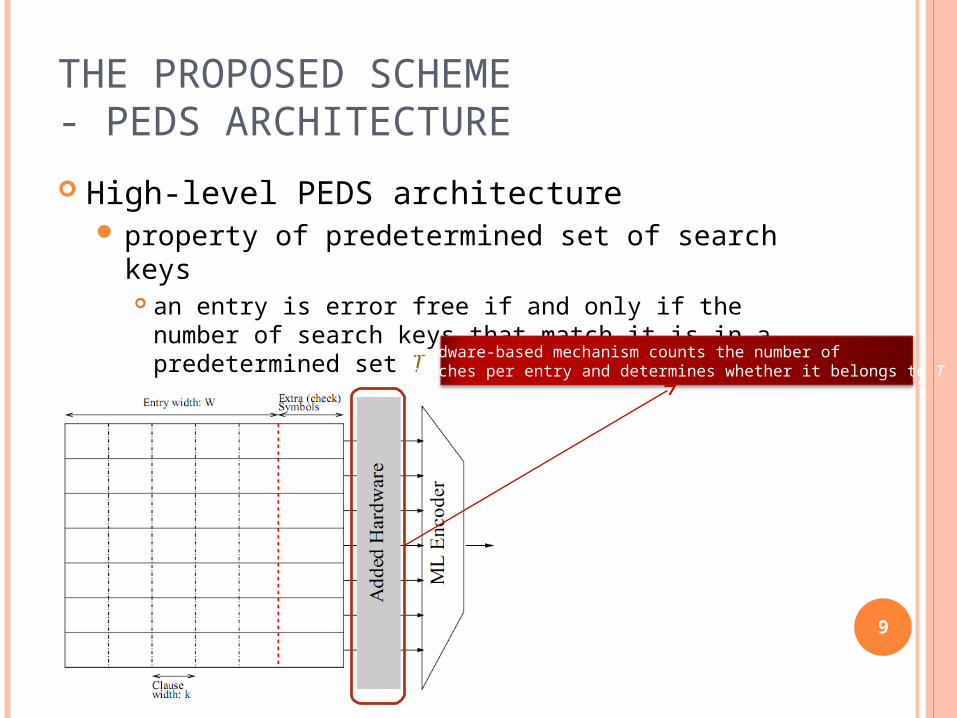
THE PROPOSED SCHEME- PEDS ARCHITECTURE
High-level PEDS architecture property of predetermined set of search keys
an entry is error free if and only if the number of search keys that match it is in a predetermined set T (int. set) eg. T = {0, 2}
9
hardware-based mechanism counts the number ofmatches per entry and determines whether it belongs to T

The Proposed Scheme - Hardware design (with mod-2 counters)
1. Regard the 3 symbols “0”, “1”, and “*” as elements of the finite field of three elements, GF(3).
Mapping: * 0; 0 +1; 1 -1
2. Encode each k-symbol clause into an n-symbol block in every entry (each block is a codeword of C)
fix the linear [n; k; d] code C over GF(3) d is the minimum (Hamming) distance between
any two distinct codewords in C, that is, every two codewords in C differ in at least d positions (and there are two codewords that differ in exactly d positions).
can detect any pattern of less than d errors that occur in codewords of C, including changes to and from “*”
10
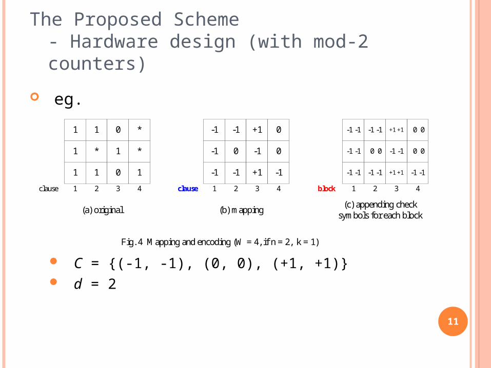
The Proposed Scheme - Hardware design (with mod-2 counters)
eg.
C = {(-1, -1), (0, 0), (+1, +1)} d = 2
11
Fig. 4 Mapping and encoding (W = 4, if n = 2, k = 1)
(a) original
1
1
1
1
1
*
21clause 3 4
0
1
0
*
1
*
(b) mapping
-1
-1
-1
-1
-1
0
21clause 3 4
+1
-1
+1
0
-1
0
(c) appending check symbols for each block
21block 3 4
-1 -1
-1 -1
-1 -1
-1 -1
-1 -1
0 0 0 0
0 0+1 +1
+1 +1
-1 -1
-1 -1
THE PROPOSED SCHEME - HARDWARE DESIGN (WITH MOD-2 COUNTERS)
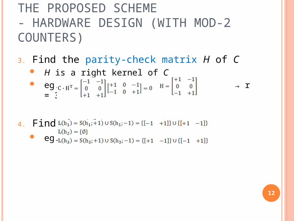
3. Find the parity-check matrix H of C H is a right kernel of C eg. , → r = 3
4. Find the L(hi) eg.
12
THE PROPOSED SCHEME - HARDWARE DESIGN (WITH MOD-2 COUNTERS)
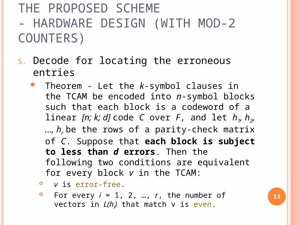
5. Decode for locating the erroneous entries Theorem - Let the k-symbol clauses in the TCAM
be encoded into n-symbol blocks such that each block is a codeword of a linear [n; k; d] code C over F, and let h1, h2,…, hr be the rows of a parity-check matrix of C. Suppose that each block is subject to less than d errors. Then the following two conditions are equivalent for every block v in the TCAM:
v is error-free. For every i = 1, 2, …, r, the number of vectors in L(hi)
that match v is even.
13

THE PROPOSED SCHEME - HARDWARE DESIGN (WITH MOD-2 COUNTERS)
Hardware change required for implementing the fast detection scheme described above.
⊕ denotes a XOR gate □ denotes a 1-bit flip-flop
14

Fig. 5-1 1st scenario of decoding (W = 4, n = 2, k = 1, r = 3)
block
1 1 1 1 0 *0 *
1 0
0 1
1 1 * * * *1 1
21 3 4
1 0 0 1 0 0 1 1
1 0
0 1
0
0
0
0
1 0
0 10
1
THE PROPOSED SCHEME - HARDWARE DESIGN (WITH MOD-2 COUNTERS)
eg.
15
0
0
0
0
0
0
0
Flag as erroneous all TCAM entries whose match linesfeed “1” to the priority encoder
1
1
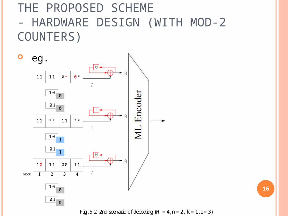
Fig. 5-2 2nd scenario of decoding (W = 4, n = 2, k = 1, r = 3)
block 21 3 4
1 1
1 1
* * * *
0 0
1 1
1 1
1 1 1 1 0 *0 *
1 0
0 1
1 0
0 1
0
0
1
1
1 0
0 1
0
0
1 0
THE PROPOSED SCHEME - HARDWARE DESIGN (WITH MOD-2 COUNTERS)
eg.
16
1
0
0
0
0
1
0
0
0

Fig. 5-3 3rd scenario of decoding (W = 4, n = 2, k = 1, r = 3)
block 21 3 4
1 1
1 1
* * * *
0 0
1 1
1 1
1 1 1 1 0 *0 *
1 0
0 1
0
0
1 0
0 1
0
0
1 0
1 00
0 11
THE PROPOSED SCHEME - HARDWARE DESIGN (WITH MOD-2 COUNTERS)
eg.
17
0
0
0
0
0
Flag as erroneous all TCAM entries whose match linesfeed “1” to the priority encoder
1
1
0
0

Fig. 5-4 4th scenario of decoding 2(W = 4, n = 2, k = 1, r = 3)
block 1 3 4
1 1
1 1
* * * *
0 0
1 1
1 1
1 1 1 1 0 *0 *
1 0
1 00
0 11
1 0
0 1
1
1
1 0
0 1
0
0
THE PROPOSED SCHEME - HARDWARE DESIGN (WITH MOD-2 COUNTERS)
eg.
18
0
0
Flag as erroneous all TCAM entries whose match linesfeed “1” to the priority encoder
1
1
0
0
1
1
1

PERFORMANCE
The parameter k defines a trade-off when d is fixed resilience
since the number of detectable errors per block is fixed, a poorer error rate requires using a smaller k
space the number of check symbols per entry is proportional
to the number W/k of blocks (clauses) per entry and, therefore, it reduces as k increases
time the number of search keys that are applied during the
decoding increases (exponentially) with k
19

PERFORMANCE
The trade-off between the space and time assuming that the parity code is used (d = 2)
with 100 information symbols (W = 100)
20
setting k to 3, 4, or 5 is the most practical choice

21