pellet boiler p4 pellet 8 - 105 - fgebiomass.co.uk · this manual contains information about the...
TRANSCRIPT

Installation Instructions
Pellet Boiler P4 Pellet 8 - 105
Translation of the original German installation instructions for techniciansRead and follow the instructions and safety information!
Technical changes, typographical errors and omissions reserved!M0931114_en | Edition 05/05/2014
Froling GesmbH | A-4710 Grieskirchen, Industriestraße 12 | www.froeling.com
Table of Contents
1 General 41.1 About this manual 4
2 Safety 52.1 Hazard levels of warnings 52.2 Qualification of assembly staff 62.3 Protective equipment for assembly staff 62.4 Design Information 72.4.1 Notes on standards 7 General standards for heating systems 7 Standards for structural and safety devices 7 Standards for heating water 7 Standards for permitted fuels 82.4.2 Installation and approval of the heating system 82.4.3 General information for installation room (boiler room) 82.4.4 Requirements for central heating water 92.4.5 Notes for using pressure maintenance systems 92.4.6 Use with storage tank 102.4.7 Chimney connection/chimney system 10 Draught limiter 10 Boiler data for planning the flue gas system 112.4.8 Room air-independent operation 122.4.9 Boiler ventilation 13
3 Technology 143.1 Dimensions P4 Pellet 8-38 143.2 Dimensions P4 Pellet 45-105 153.3 Supply air connections for room air-independent operation 163.4 Flue gas pipe position 163.5 Components and connections 173.5.1 P4 Pellet 8-38 173.5.2 P4 Pellet 45-105 183.6 Technical specifications 193.6.1 P4 Pellet 8 – 25 193.6.2 P4 Pellet 32 – 60 203.6.3 P4 Pellet 70 – 105 213.6.4 Airborne sound level 23
4 Assembly 244.1 Materials supplied 244.1.1 Tools required 244.2 Positioning 244.3 Temporary storage 254.4 Setting up in the boiler room 264.4.1 Remove boiler from pallet 264.4.2 Moving the boiler in the boiler room 274.4.3 Minimum distances in the boiler room 28
Table of Contents
2 Froling GesmbH | A-4710 Grieskirchen, Industriestraße 12 | www.froeling.com
4.5 Dismantling for location where positioning is difficult 294.5.1 Removing the stoker assembly and insulation 294.5.2 Removing the door and ash drawer (P4 Pellet 8 - 25) 304.5.3 Dismantling the suction cyclone cover 314.5.4 Dismantling the stoker unit 324.5.5 Positioning dimensions after dismantling 354.5.6 Notes for reassembly 364.6 Assembling the pellet boiler 374.6.1 Before Installation 37 Checking the seal of the ash doors 37 Adjusting the doors 374.6.2 Fitting the induced draught fan 404.6.3 Fitting the ash container and doors (P4 Pellet 32 - 105) 414.7 Connecting the discharge system 424.8 Power connection 434.8.1 Information on circulating pumps 444.8.2 Comfort pellet box port 45
5 Start-up 465.1 Before commissioning / configuring the boiler 465.1.1 Setting the "Max level and Min level” sensor 475.2 Initial startup 475.2.1 Permitted fuels 47 Wood pellets 475.2.2 Non-permitted fuels 475.2.3 Heating up for the first time 48
6 Decommissioning 496.1 Mothballing 496.2 Disassembly 496.3 Disposal 49
7 Appendix 507.1 Addresses 507.1.1 Address of manufacturer 507.1.2 Address of the installer 50
Table of Contents
Installation Instructions P4 Pellet 8 - 105 | M0931114_en 3
1 GeneralThank you for choosing a quality product from Froling. The product features a state-of-the-art design and conforms to all currently applicable standards and testing guide‐lines.Please read and observe the documentation provided and always keep it close to thesystem for reference. Observing the requirements and safety information in the docu‐mentation makes a significant contribution to safe, appropriate, environmentally friend‐ly and economical operation of the system.The constant further development of our products means that there may be minor dif‐ferences from the pictures and content. If you discover any errors, please let us know:[email protected] to technical change. The EC Declaration of Conformity is only valid in conjunction with a delivery certificate,which has been filled in correctly and signed as part of the commissioning process.The original document remains at the installation site. Commissioning installers orheating engineers are requested to return a copy of the delivery certificate togetherwith the guarantee card to Froling. On commissioning by FROLING Customer Servicethe validity of the delivery certificate will be noted on the customer service record.
1.1 About this manualThis manual contains information about the following sizes of the pellet boiler P4:P4 Pellet 8, P4 Pellet 15, P4 Pellet 20, P4 Pellet 25, P4 Pellet 32, P4 Pellet 38,P4 Pellet 451), P4 Pellet 48, P4 Pellet 60, P4 Pellet 702), P4 Pellet 80, P4 Pellet 100 (99kW)3), P4 Pellet 100, P4 Pellet 1054)
1) P4 Pellet 45 is only available in the UK; 2) P4 Pellet 70 is only available in France;
3) P4 Pellet 100 with nominal heat output of 99kW is only available in the UK; 4) P4 Pellet 105 is only available in Germany
Issuing a delivery cer‐tificate
1 GeneralAbout this manual
4 Froling GesmbH | A-4710 Grieskirchen, Industriestraße 12 | www.froeling.com
2 Safety
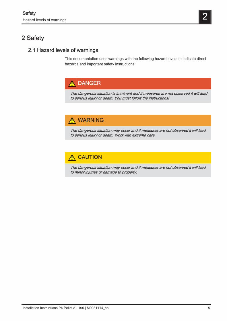
2.1 Hazard levels of warningsThis documentation uses warnings with the following hazard levels to indicate directhazards and important safety instructions:
DANGER
The dangerous situation is imminent and if measures are not observed it will leadto serious injury or death. You must follow the instructions!
WARNING
The dangerous situation may occur and if measures are not observed it will leadto serious injury or death. Work with extreme care.
CAUTION
The dangerous situation may occur and if measures are not observed it will leadto minor injuries or damage to property.
Safety 2Hazard levels of warnings
Installation Instructions P4 Pellet 8 - 105 | M0931114_en 5
2.2 Qualification of assembly staff
CAUTION
Assembly and installation by untrained personnel:
Risk of personal injury and damage to property.
During assembly and installation:❒ Observe the instructions and information in the manuals❒ Only allow trained staff to carry out assembly and installation
Assembly, installation, initial startup and servicing must always be carried out by quali‐fied personnel:- Heating technician / building technician- Electrical installation technician- Froling customer servicesThe assembly staff must have read and understood the instructions in the documenta‐tion.
2.3 Protective equipment for assembly staffYou must ensure that staff have the protective equipment specified by accident pre‐vention regulations.
▪ For transportation, setup and assembly:- suitable workwear- protective gloves- sturdy shoes
2 SafetyQualification of assembly staff
6 Froling GesmbH | A-4710 Grieskirchen, Industriestraße 12 | www.froeling.com

2.4 Design Information
2.4.1 Notes on standardsThe system must be installed and commissioned in accordance with the local fire andbuilding regulations. The following standards and regulations should always be ob‐served:
General standards for heating systems
EN 303-5 Boilers for solid fuels, manually and automatically fed combus‐tion systems, nominal heat output up to 500 kW
EN 12828 Heating systems in buildings - design of water-based heatingsystems
EN 13384-1 Chimneys - Thermal and fluid dynamic calculation methodsPart 1: Chimneys serving one appliance
ÖNORM M 7510-1 Guidelines for checking central heating systemsPart 1: General requirements and one-off inspections
ÖNORM M 7510-4 Guidelines for checking central heating systemsPart 4: Simple check for heating plants for solid fuels
Standards for structural and safety devices
ÖNORM H 5170 Heating installation - Requirements for construction and safetyengineering, as well as fire prevention and environmental pro‐tection
ÖNORM M 7137 Compressed untreated wood – Requirements for storing pelletsat the end customer’s site
TRVB H 118 Technical directives for fire protection/prevention (Austria)
Standards for heating water
ÖNORM H 5195-1 Prevention of damage by corrosion and scale formation inclosed warm water heating systems at operating temperaturesup to 100 °C (Austria)
VDI 2035 Prevention of damage in water heating systems (Germany)
SWKI 97-1 Water quality for heating, steam, cooling and air conditioningsystems (Switzerland)
D.P.R. n° 412 Regulations for the planning, installation, running/operation andmaintenance of heating systems in buildings to reduce energyconsumption with reference to Article 4, Comma 4 of the Legis‐lative Decree of 9 January 1991, No. 10 (Italy)
Safety 2Design Information
Installation Instructions P4 Pellet 8 - 105 | M0931114_en 7
Standards for permitted fuels
EN 14961-2 Solid biofuel, fuel specifications and classes.Part 2: Wood pellets for non-industrial use
1. BImSchV First Ordinance of the German Federal Government for imple‐mentation of the Federal Emission Protection Law, BGBl. I P.491, in the applicable version.
2.4.2 Installation and approval of the heating systemThe boiler should be operated in a closed heating system. The following standardsgovern the installation:
ÖNORM / DIN EN 12828 Heating Systems in Buildings
NOTICE! Each heating system must be officially approved.The appropriate supervisory authority (inspection agency) must always be informedwhen installing or modifying a heating system, and authorisation must be obtainedfrom the building authorities:Austria: Inform the civic/municipal building authorities.Germany: Notify an approved chimney sweep and the building authorities.
2.4.3 General information for installation room (boiler room)
Boiler room characteristics▪ There must not be a potentially explosive atmosphere in the boiler room as the
boiler is not suitable for use in potentially explosive environments.▪ The boiler room must be frost-free.▪ The boiler does not provide any light, so the customer must provide sufficient light‐
ing in the boiler room in accordance with national workplace design regulations.▪ When using the boiler over 2000 metres above sea level you should consult the
manufacturer.▪ Danger of fire due to flammable materials.
No flammable materials should be stored near the boiler. Flammable objects (e.g.clothing) must not be put on the boiler to dry.
▪ Damage due to impurities in combustion air.Do not use any solvents or cleaning agents containing chlorine in the room wherethe boiler is installed.
▪ Keep the air suction opening of the boiler free from dust.
Ventilation of the boiler roomVentilation air for the boiler room should be taken from and expelled directly outside,and the openings and air ducts should be designed to prevent weather conditions (foli‐age, snowdrifts, etc.) from obstructing the air flow.
Note on standards
2 SafetyDesign Information
8 Froling GesmbH | A-4710 Grieskirchen, Industriestraße 12 | www.froeling.com
Unless otherwise specified in the applicable building regulations for the boiler room,the following standards apply to the design and dimensions of the air ducts:
ÖNORM H 5170 - Construction and fire protection requirementsTRVB H118 - Technical directives on fire protection/prevention
2.4.4 Requirements for central heating waterThe following standards and guidelines apply:
Austria:Germany:Switzerland:Italy:
ÖNORM H 5195-1VDI 2035SWKI 97-1D.P.R. no. 412
NOTICE! Note on filling with make-up water: always bleed the filling hose before con‐necting, in order to prevent air from entering the system. Observe the standards and also follow the recommendations below:❒ Max. cumulative value for alkaline earth: 1.0 mmol/l or 100 mg/l (corresponds to
5.6 dH)❒ Use softened water as the make-up water❒ Avoid leaks and use a closed heating system to maintain water quality during op‐
eration
2.4.5 Notes for using pressure maintenance systemsPressure maintenance systems in hot-water heating systems keep the required pres‐sure within predefined limits and balance out volume variations caused by changes inthe hot-water temperature. Two main systems are used:
Compressor-controlled pressure maintenance
In compressor-controlled pressure maintenance units, a variable air cushion in the ex‐pansion tank is responsible for volume compensation and pressure maintenance. Ifthe pressure is too low, the compressor pumps air into the tank. If the pressure is toohigh, air is released by means of a solenoid valve. The systems are built solely withclosed-diaphragm expansion tanks to prevent the damaging introduction of oxygen in‐to the heating water.
Pump-controlled pressure maintenance
A pump-controlled pressure maintenance unit essentially consists of a pressure-main‐tenance pump, relief valve and an unpressurised receiving tank. The valve releaseshot water into the receiving tank if the pressure is too high. If the pressure drops belowa preset value, the pump draws water from the receiving tank and feeds it back intothe heating system. Pump-controlled pressure maintenance systems with open expan‐sion tanks (e.g. without a diaphragm) introduce ambient oxygen via the surface of thewater, exposing the connected system components to the risk of corrosion. Thesesystems offer no oxygen removal for the purposes of corrosion control as required byVDI 2035 and in the interests of corrosion protection should not be used.
Note on standards
Note on standards
Safety 2Design Information
Installation Instructions P4 Pellet 8 - 105 | M0931114_en 9
2.4.6 Use with storage tank
NOTICE
In principle it is not necessary to use a storage tank for the system to run smooth‐ly. However, we recommend that you use the system with a storage tank, as thisensures a continuous supply of fuel in the ideal output range of the boiler.
For the correct dimensions of the storage tank and the line insulation (in accordancewith ÖNORM M 7510 or guideline UZ37) please consult your installer or Froling. ⇨ See "Addresses" [page 50]
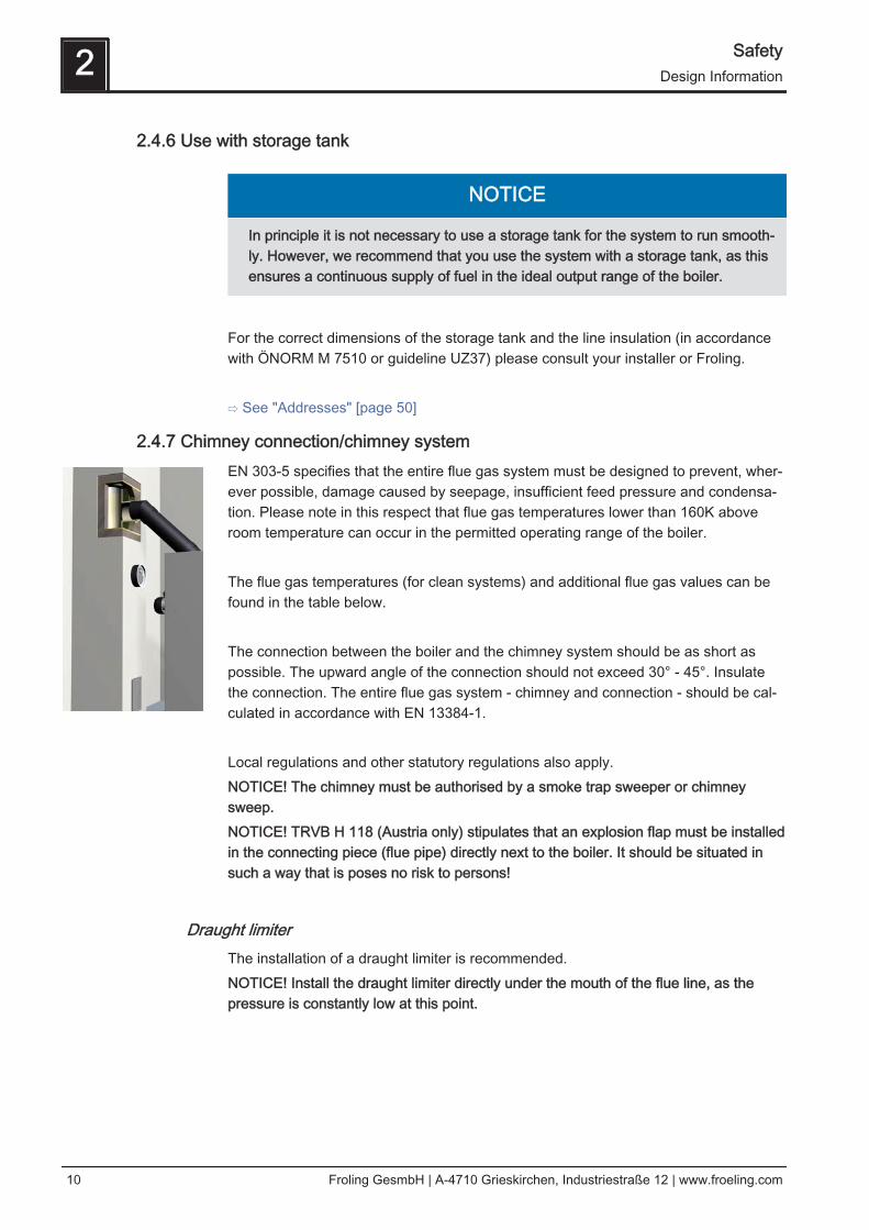
2.4.7 Chimney connection/chimney systemEN 303-5 specifies that the entire flue gas system must be designed to prevent, wher‐ever possible, damage caused by seepage, insufficient feed pressure and condensa‐tion. Please note in this respect that flue gas temperatures lower than 160K aboveroom temperature can occur in the permitted operating range of the boiler. The flue gas temperatures (for clean systems) and additional flue gas values can befound in the table below. The connection between the boiler and the chimney system should be as short aspossible. The upward angle of the connection should not exceed 30° - 45°. Insulatethe connection. The entire flue gas system - chimney and connection - should be cal‐culated in accordance with EN 13384-1. Local regulations and other statutory regulations also apply.NOTICE! The chimney must be authorised by a smoke trap sweeper or chimneysweep.NOTICE! TRVB H 118 (Austria only) stipulates that an explosion flap must be installedin the connecting piece (flue pipe) directly next to the boiler. It should be situated insuch a way that is poses no risk to persons!
Draught limiterThe installation of a draught limiter is recommended.NOTICE! Install the draught limiter directly under the mouth of the flue line, as thepressure is constantly low at this point.
2 SafetyDesign Information
10 Froling GesmbH | A-4710 Grieskirchen, Industriestraße 12 | www.froeling.com
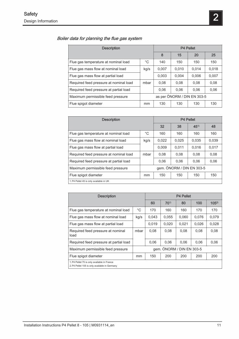
Boiler data for planning the flue gas system
Description P4 Pellet
8 15 20 25
Flue gas temperature at nominal load °C 140 150 150 150
Flue gas mass flow at nominal load kg/s 0,007 0,010 0,014 0,018
Flue gas mass flow at partial load 0,003 0,004 0,006 0,007
Required feed pressure at nominal load mbar 0,08 0,08 0,08 0,08
Required feed pressure at partial load 0,06 0,06 0,06 0,06
Maximum permissible feed pressure as per ÖNORM / DIN EN 303-5
Flue spigot diameter mm 130 130 130 130
Description P4 Pellet
32 38 451) 48
Flue gas temperature at nominal load °C 160 160 160 160
Flue gas mass flow at nominal load kg/s 0,022 0,025 0,035 0,039
Flue gas mass flow at partial load 0,009 0,011 0,016 0,017
Required feed pressure at nominal load mbar 0,08 0,08 0,08 0,08
Required feed pressure at partial load 0,06 0,06 0,06 0,06
Maximum permissible feed pressure gem. ÖNORM / DIN EN 303-5
Flue spigot diameter mm 150 150 150 1501.P4 Pellet 45 is only available in UK
Description P4 Pellet
60 701) 80 100 1052)
Flue gas temperature at nominal load °C 170 160 160 170 170
Flue gas mass flow at nominal load kg/s 0,043 0,055 0,060 0,076 0,079
Flue gas mass flow at partial load 0,019 0,020 0,021 0,026 0,028
Required feed pressure at nominalload
mbar 0,08 0,08 0,08 0,08 0,08
Required feed pressure at partial load 0,06 0,06 0,06 0,06 0,06
Maximum permissible feed pressure gem. ÖNORM / DIN EN 303-5
Flue spigot diameter mm 150 200 200 200 2001.P4 Pellet 70 is only available in France2.P4 Pellet 105 is only available in Germany
Safety 2Design Information
Installation Instructions P4 Pellet 8 - 105 | M0931114_en 11
2.4.8 Room air-independent operationThe P4 Pellet has a central air connection on the back of the boiler. If appropriate sup‐ply air and flue gas connections are installed, the boiler can be operated independent‐ly of room air as a type C42 or type C82 in the sense of EN 15035.
Definition of type C8 as per EN 15035
A boiler that is connected via its combustion air supply and flue gas outlet, with a con‐necting piece that may be supplied, to a shared chimney with a shaft for combustionair supply and a shaft for flue gas outlet. The mouths of the air and flue gas chimneyare either concentric or so close to each other that similar wind conditions apply.NOTICE! Air is supplied by an air and flue gas system!
Definition of type C8 as per EN 15035
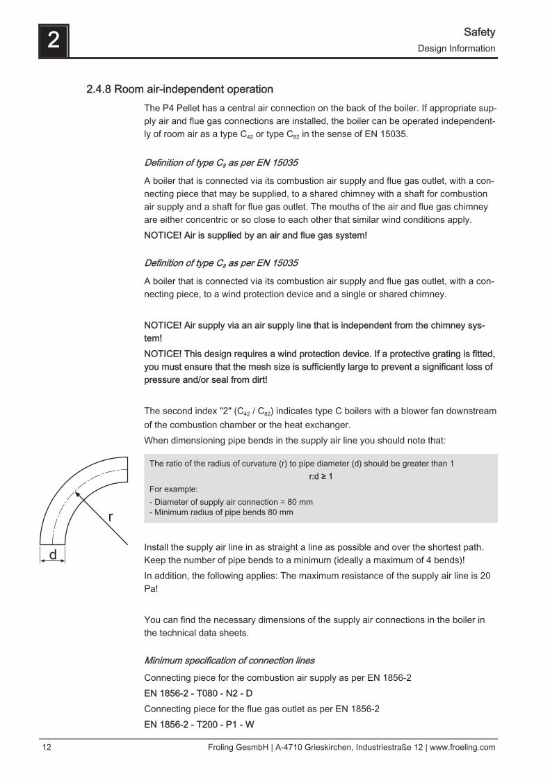
A boiler that is connected via its combustion air supply and flue gas outlet, with a con‐necting piece, to a wind protection device and a single or shared chimney. NOTICE! Air supply via an air supply line that is independent from the chimney sys‐tem!NOTICE! This design requires a wind protection device. If a protective grating is fitted,you must ensure that the mesh size is sufficiently large to prevent a significant loss ofpressure and/or seal from dirt! The second index "2" (C42 / C82) indicates type C boilers with a blower fan downstreamof the combustion chamber or the heat exchanger.When dimensioning pipe bends in the supply air line you should note that:
The ratio of the radius of curvature (r) to pipe diameter (d) should be greater than 1r:d ≥ 1
For example:- Diameter of supply air connection = 80 mm- Minimum radius of pipe bends 80 mm
Install the supply air line in as straight a line as possible and over the shortest path.Keep the number of pipe bends to a minimum (ideally a maximum of 4 bends)!In addition, the following applies: The maximum resistance of the supply air line is 20Pa! You can find the necessary dimensions of the supply air connections in the boiler inthe technical data sheets.
Minimum specification of connection lines
Connecting piece for the combustion air supply as per EN 1856-2EN 1856-2 - T080 - N2 - DConnecting piece for the flue gas outlet as per EN 1856-2EN 1856-2 - T200 - P1 - W
2 SafetyDesign Information
12 Froling GesmbH | A-4710 Grieskirchen, Industriestraße 12 | www.froeling.com
TXXX Temperature class (specified in °C)
N2 Pressure class with test pressure = 20 Pa
P1 Pressure class with test pressure = 200 Pa
D Condensation resistance not required (dry)
W Condensation resistance required (damp)
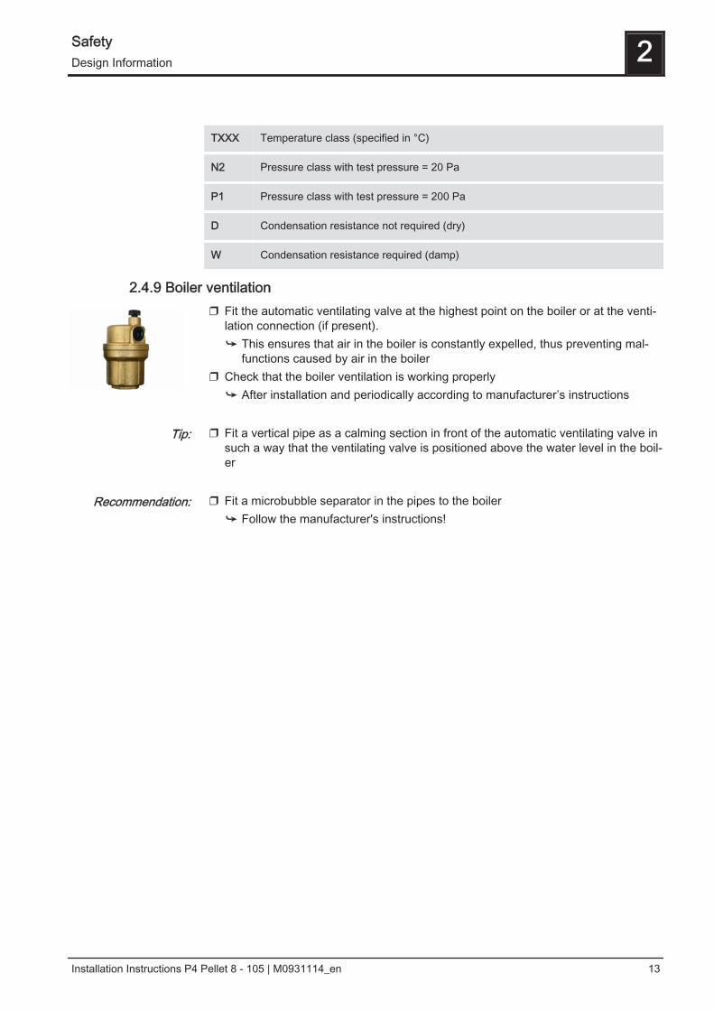
2.4.9 Boiler ventilation❒ Fit the automatic ventilating valve at the highest point on the boiler or at the venti‐
lation connection (if present).➥ This ensures that air in the boiler is constantly expelled, thus preventing mal‐
functions caused by air in the boiler❒ Check that the boiler ventilation is working properly
➥ After installation and periodically according to manufacturer’s instructions ❒ Fit a vertical pipe as a calming section in front of the automatic ventilating valve in
such a way that the ventilating valve is positioned above the water level in the boil‐er
❒ Fit a microbubble separator in the pipes to the boiler
➥ Follow the manufacturer's instructions!
Tip:
Recommendation:
Safety 2Design Information
Installation Instructions P4 Pellet 8 - 105 | M0931114_en 13
3 TechnologyNOTICE! Some sizes of the boiler P4 Pellet are not available in every country
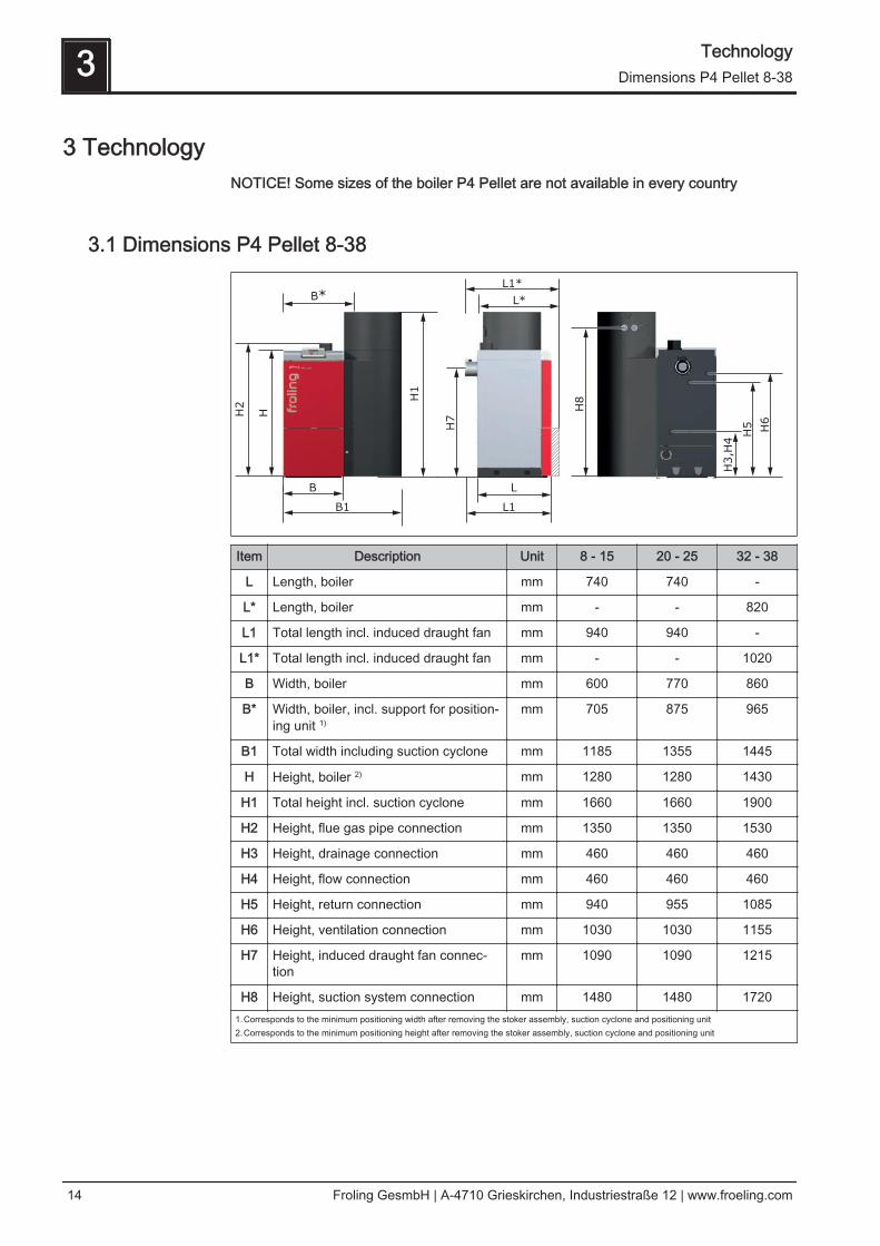
3.1 Dimensions P4 Pellet 8-38
Item Description Unit 8 - 15 20 - 25 32 - 38
L Length, boiler mm 740 740 -
L* Length, boiler mm - - 820
L1 Total length incl. induced draught fan mm 940 940 -
L1* Total length incl. induced draught fan mm - - 1020
B Width, boiler mm 600 770 860
B* Width, boiler, incl. support for position‐ing unit 1)
mm 705 875 965
B1 Total width including suction cyclone mm 1185 1355 1445
H Height, boiler 2) mm 1280 1280 1430
H1 Total height incl. suction cyclone mm 1660 1660 1900
H2 Height, flue gas pipe connection mm 1350 1350 1530
H3 Height, drainage connection mm 460 460 460
H4 Height, flow connection mm 460 460 460
H5 Height, return connection mm 940 955 1085
H6 Height, ventilation connection mm 1030 1030 1155
H7 Height, induced draught fan connec‐tion
mm 1090 1090 1215
H8 Height, suction system connection mm 1480 1480 17201.Corresponds to the minimum positioning width after removing the stoker assembly, suction cyclone and positioning unit2.Corresponds to the minimum positioning height after removing the stoker assembly, suction cyclone and positioning unit
3 TechnologyDimensions P4 Pellet 8-38
14 Froling GesmbH | A-4710 Grieskirchen, Industriestraße 12 | www.froeling.com
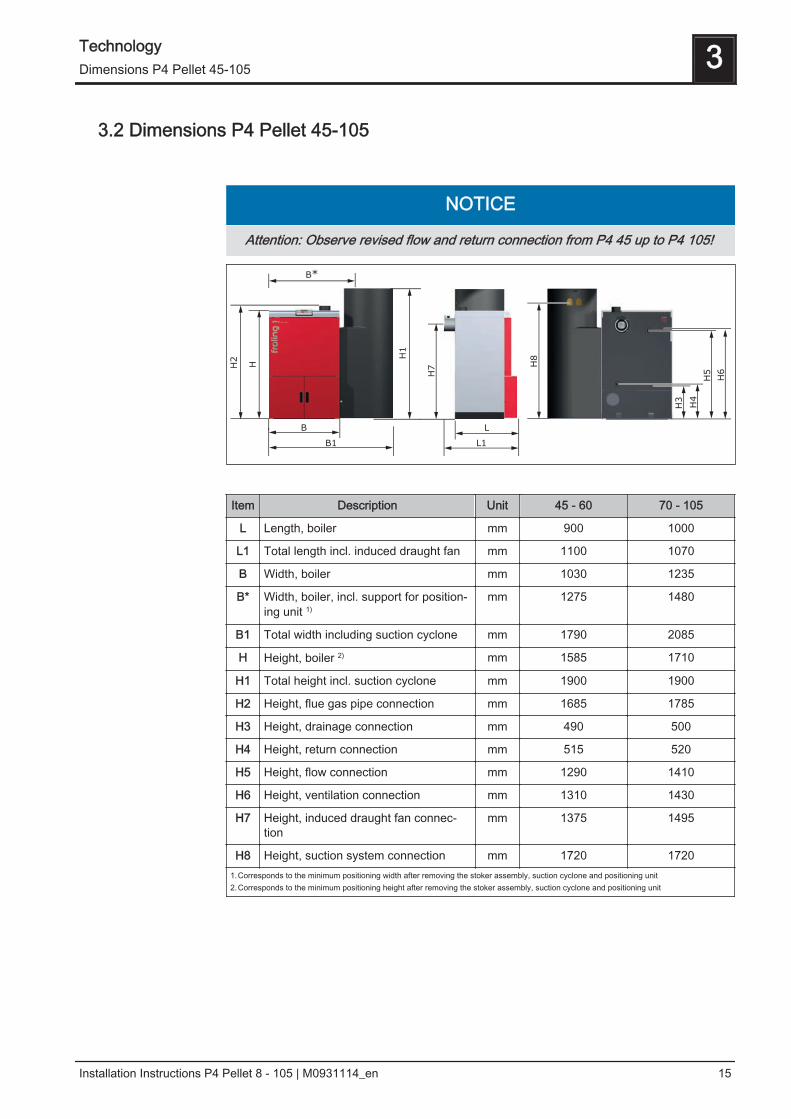
3.2 Dimensions P4 Pellet 45-105
NOTICE
Attention: Observe revised flow and return connection from P4 45 up to P4 105!
Item Description Unit 45 - 60 70 - 105
L Length, boiler mm 900 1000
L1 Total length incl. induced draught fan mm 1100 1070
B Width, boiler mm 1030 1235
B* Width, boiler, incl. support for position‐ing unit 1)
mm 1275 1480
B1 Total width including suction cyclone mm 1790 2085
H Height, boiler 2) mm 1585 1710
H1 Total height incl. suction cyclone mm 1900 1900
H2 Height, flue gas pipe connection mm 1685 1785
H3 Height, drainage connection mm 490 500
H4 Height, return connection mm 515 520
H5 Height, flow connection mm 1290 1410
H6 Height, ventilation connection mm 1310 1430
H7 Height, induced draught fan connec‐tion
mm 1375 1495
H8 Height, suction system connection mm 1720 17201.Corresponds to the minimum positioning width after removing the stoker assembly, suction cyclone and positioning unit2.Corresponds to the minimum positioning height after removing the stoker assembly, suction cyclone and positioning unit
Technology 3Dimensions P4 Pellet 45-105
Installation Instructions P4 Pellet 8 - 105 | M0931114_en 15
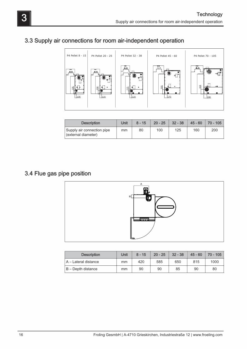
3.3 Supply air connections for room air-independent operation
100 115 115 170
235
230
215
305
315
190
Description Unit 8 - 15 20 - 25 32 - 38 45 - 60 70 - 105
Supply air connection pipe(external diameter)
mm 80 100 125 160 200
3.4 Flue gas pipe position
Description Unit 8 - 15 20 - 25 32 - 38 45 - 60 70 - 105
A – Lateral distance mm 420 585 650 815 1000
B – Depth distance mm 90 90 85 90 80
3 TechnologySupply air connections for room air-independent operation
16 Froling GesmbH | A-4710 Grieskirchen, Industriestraße 12 | www.froeling.com
3.5 Components and connections
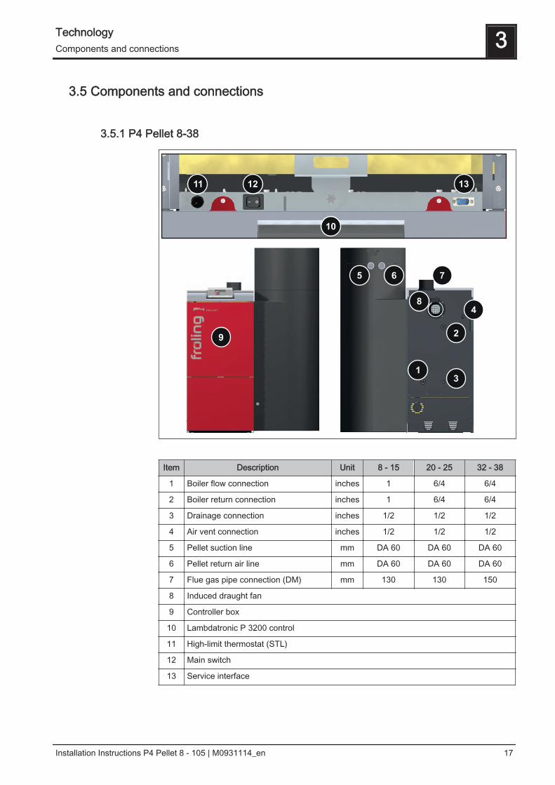
3.5.1 P4 Pellet 8-38
Item Description Unit 8 - 15 20 - 25 32 - 38
1 Boiler flow connection inches 1 6/4 6/4
2 Boiler return connection inches 1 6/4 6/4
3 Drainage connection inches 1/2 1/2 1/2
4 Air vent connection inches 1/2 1/2 1/2
5 Pellet suction line mm DA 60 DA 60 DA 60
6 Pellet return air line mm DA 60 DA 60 DA 60
7 Flue gas pipe connection (DM) mm 130 130 150
8 Induced draught fan
9 Controller box
10 Lambdatronic P 3200 control
11 High-limit thermostat (STL)
12 Main switch
13 Service interface
Technology 3Components and connections
Installation Instructions P4 Pellet 8 - 105 | M0931114_en 17
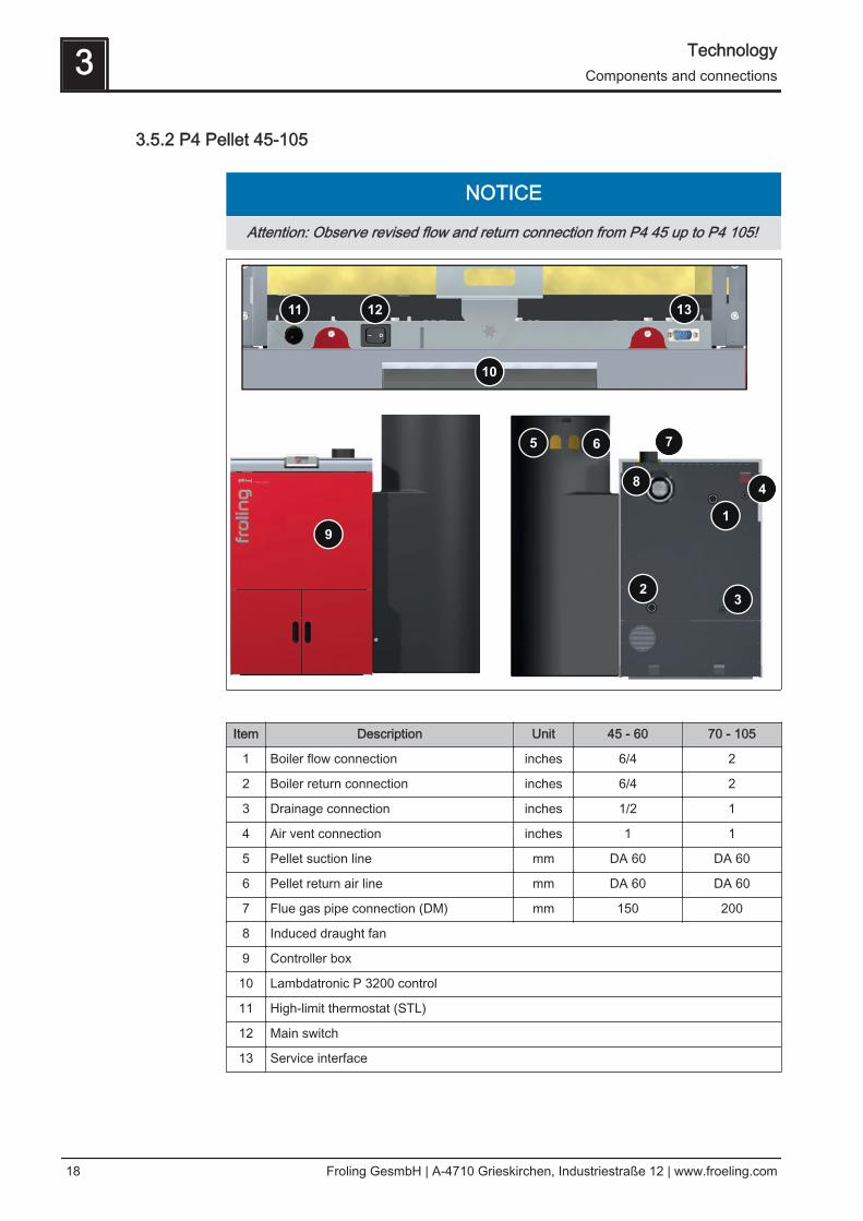
3.5.2 P4 Pellet 45-105
NOTICE
Attention: Observe revised flow and return connection from P4 45 up to P4 105!
Item Description Unit 45 - 60 70 - 105
1 Boiler flow connection inches 6/4 2
2 Boiler return connection inches 6/4 2
3 Drainage connection inches 1/2 1
4 Air vent connection inches 1 1
5 Pellet suction line mm DA 60 DA 60
6 Pellet return air line mm DA 60 DA 60
7 Flue gas pipe connection (DM) mm 150 200
8 Induced draught fan
9 Controller box
10 Lambdatronic P 3200 control
11 High-limit thermostat (STL)
12 Main switch
13 Service interface
3 TechnologyComponents and connections
18 Froling GesmbH | A-4710 Grieskirchen, Industriestraße 12 | www.froeling.com
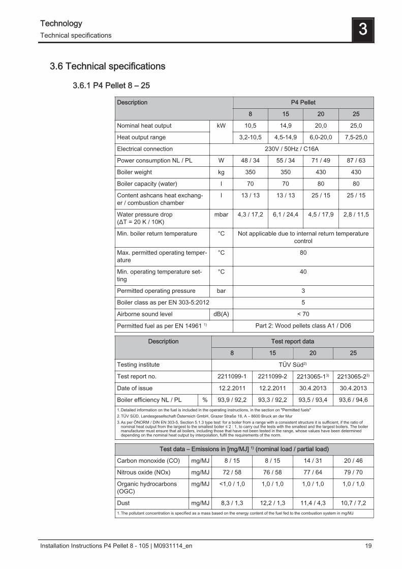
3.6 Technical specifications
3.6.1 P4 Pellet 8 – 25
Description P4 Pellet
8 15 20 25
Nominal heat output kW 10,5 14,9 20,0 25,0
Heat output range 3,2-10,5 4,5-14,9 6,0-20,0 7,5-25,0
Electrical connection 230V / 50Hz / C16A
Power consumption NL / PL W 48 / 34 55 / 34 71 / 49 87 / 63
Boiler weight kg 350 350 430 430
Boiler capacity (water) l 70 70 80 80
Content ashcans heat exchang‐er / combustion chamber
l 13 / 13 13 / 13 25 / 15 25 / 15
Water pressure drop(ΔT = 20 K / 10K)
mbar 4,3 / 17,2 6,1 / 24,4 4,5 / 17,9 2,8 / 11,5
Min. boiler return temperature °C Not applicable due to internal return temperaturecontrol
Max. permitted operating temper‐ature
°C 80
Min. operating temperature set‐ting
°C 40
Permitted operating pressure bar 3
Boiler class as per EN 303-5:2012 5
Airborne sound level dB(A) < 70
Permitted fuel as per EN 14961 1) Part 2: Wood pellets class A1 / D06
Description Test report data
8 15 20 25
Testing institute TÜV Süd2)
Test report no. 2211099-1 2211099-2 2213065-13) 2213065-23)
Date of issue 12.2.2011 12.2.2011 30.4.2013 30.4.2013
Boiler efficiency NL / PL % 93,9 / 92,2 93,3 / 92,2 93,5 / 93,4 93,6 / 94,61.Detailed information on the fuel is included in the operating instructions, in the section on "Permitted fuels"2.TÜV SÜD, Landesgesellschaft Österreich GmbH, Grazer Straße 18, A – 8600 Bruck an der Mur3.As per ÖNORM / DIN EN 303-5, Section 5.1.3 type test: for a boiler from a range with a consistent structure it is sufficient, if the ratio of
nominal heat output from the largest to the smallest boiler ≤ 2 : 1, to carry out the tests with the smallest and the largest boilers. The boilermanufacturer must ensure that all boilers, including those that have not been tested in the range, whose values have been determineddepending on the nominal heat output by interpolation, fulfil the requirements of the norm.
Test data – Emissions in [mg/MJ] 1) (nominal load / partial load)
Carbon monoxide (CO) mg/MJ 8 / 15 8 / 15 14 / 31 20 / 46
Nitrous oxide (NOx) mg/MJ 72 / 58 76 / 58 77 / 64 79 / 70
Organic hydrocarbons(OGC)
mg/MJ <1,0 / 1,0 1,0 / 1,0 1,0 / 1,0 1,0 / 1,0
Dust mg/MJ 8,3 / 1,3 12,2 / 1,3 11,4 / 4,3 10,7 / 7,21.The pollutant concentration is specified as a mass based on the energy content of the fuel fed to the combustion system in mg/MJ
Technology 3Technical specifications
Installation Instructions P4 Pellet 8 - 105 | M0931114_en 19

Test data – Emissions in [mg/m3] 1) (nominal load / partial load)
Carbon monoxide (CO) mg/m³ 12 / 23 12 / 23 22 / 48 31 / 72
Nitrous oxide (NOx) mg/m³ 110 / 89 117 / 89 119 / 98 121 / 107
Organic hydrocarbons(OGC)
mg/m³ <1,0 / 1,0 1,0 / 1,0 1,0 / 1,3 1,0 / 1,7
Dust mg/m³ 12,7 / 2,0 18,7 / 2,0 17,8 / 7,1 16,9 / 12,21.Emissions values based on dry flue gas at standard temperature and pressure (0°C, 1013 mbar) with a volume content of oxygen of 13%
3.6.2 P4 Pellet 32 – 60
Description P4 Pellet
32 38 451) 48 60
Nominal heat output kW 32,0 38,0 45,0 48,0 58,5
Heat output range 9,6-32,0 11,4-38,0 13,5-45,0 14,4-48,0 17,6-58,5
Electrical connection 230V / 50Hz / C16A
Power consumption NL/PL W 104 / 78 110 / 78 113 / 78 114 / 45 119 / 80
Boiler weight kg 530 530 760 760 760
Boiler capacity (water) l 125 125 170 170 170
Content ash containersheat exchanger / combus‐tion chamber
l 33 / 19 33 / 19 33 / 33 33 / 33 33 / 33
Water pressure drop (ΔT = 20 K / 10K)
mbar 1,5 / 6,2 2,1 / 8,7 3,2 / 9,9 3,7 / 10,5 5,3 / 12,3
Min. boiler return tempera‐ture
°C Not applicable due to internal return temperature control
Max. permitted operatingtemperature
80
Min. operating tempera‐ture setting
40
Permitted operating pres‐sure
bar 3
Boiler class as per EN 303-5:2012 5
Airborne sound level dB(A) < 70
Permitted fuel as per EN 14961 1) Part 2: Wood pellets class A1 / D06
3 TechnologyTechnical specifications
20 Froling GesmbH | A-4710 Grieskirchen, Industriestraße 12 | www.froeling.com
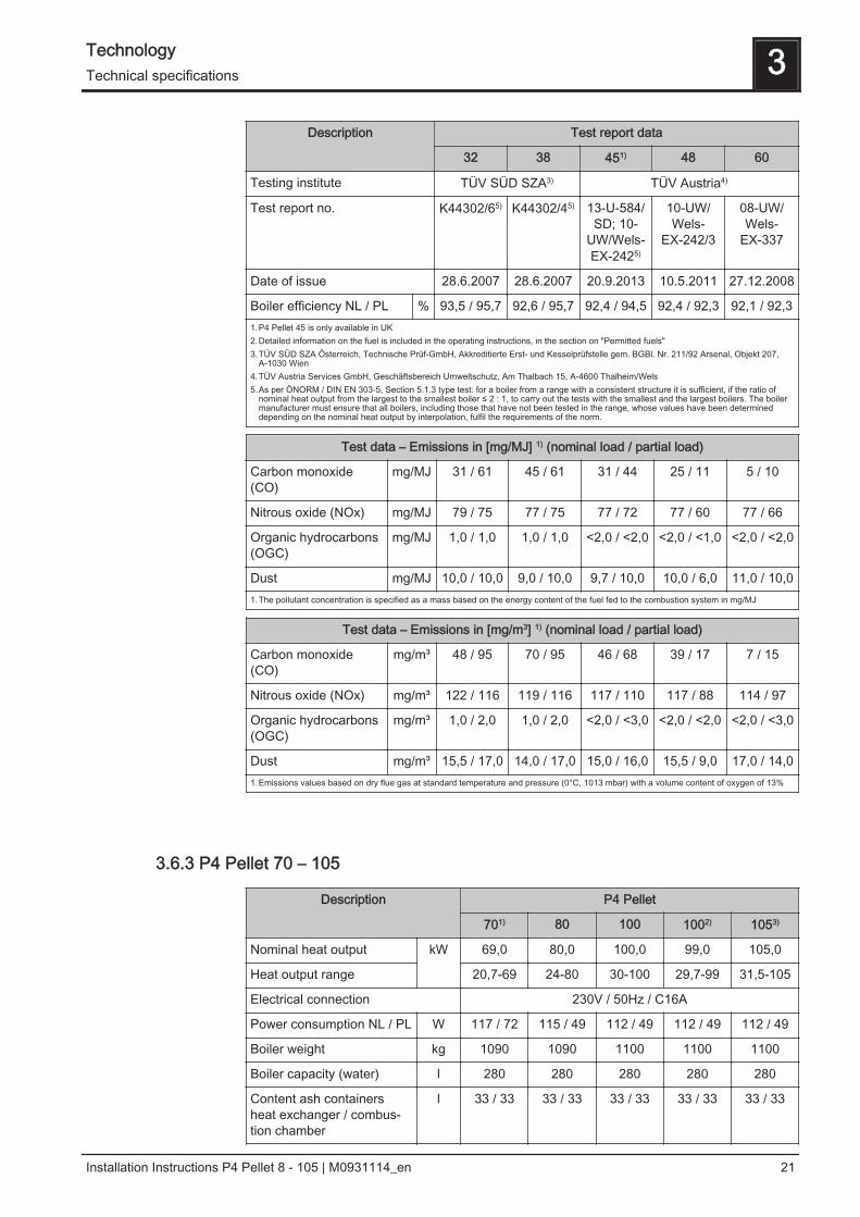
Description Test report data
32 38 451) 48 60
Testing institute TÜV SÜD SZA3) TÜV Austria4)
Test report no. K44302/65) K44302/45) 13-U-584/SD; 10-
UW/Wels-EX-2425)
10-UW/Wels-
EX-242/3
08-UW/Wels-
EX-337
Date of issue 28.6.2007 28.6.2007 20.9.2013 10.5.2011 27.12.2008
Boiler efficiency NL / PL % 93,5 / 95,7 92,6 / 95,7 92,4 / 94,5 92,4 / 92,3 92,1 / 92,31.P4 Pellet 45 is only available in UK2.Detailed information on the fuel is included in the operating instructions, in the section on "Permitted fuels"3.TÜV SÜD SZA Österreich, Technische Prüf-GmbH, Akkreditierte Erst- und Kesselprüfstelle gem. BGBl. Nr. 211/92 Arsenal, Objekt 207,
A-1030 Wien4.TÜV Austria Services GmbH, Geschäftsbereich Umweltschutz, Am Thalbach 15, A-4600 Thalheim/Wels5.As per ÖNORM / DIN EN 303-5, Section 5.1.3 type test: for a boiler from a range with a consistent structure it is sufficient, if the ratio of
nominal heat output from the largest to the smallest boiler ≤ 2 : 1, to carry out the tests with the smallest and the largest boilers. The boilermanufacturer must ensure that all boilers, including those that have not been tested in the range, whose values have been determineddepending on the nominal heat output by interpolation, fulfil the requirements of the norm.
Test data – Emissions in [mg/MJ] 1) (nominal load / partial load)
Carbon monoxide(CO)
mg/MJ 31 / 61 45 / 61 31 / 44 25 / 11 5 / 10
Nitrous oxide (NOx) mg/MJ 79 / 75 77 / 75 77 / 72 77 / 60 77 / 66
Organic hydrocarbons(OGC)
mg/MJ 1,0 / 1,0 1,0 / 1,0 <2,0 / <2,0 <2,0 / <1,0 <2,0 / <2,0
Dust mg/MJ 10,0 / 10,0 9,0 / 10,0 9,7 / 10,0 10,0 / 6,0 11,0 / 10,01.The pollutant concentration is specified as a mass based on the energy content of the fuel fed to the combustion system in mg/MJ
Test data – Emissions in [mg/m3] 1) (nominal load / partial load)
Carbon monoxide(CO)
mg/m³ 48 / 95 70 / 95 46 / 68 39 / 17 7 / 15
Nitrous oxide (NOx) mg/m³ 122 / 116 119 / 116 117 / 110 117 / 88 114 / 97
Organic hydrocarbons(OGC)
mg/m³ 1,0 / 2,0 1,0 / 2,0 <2,0 / <3,0 <2,0 / <2,0 <2,0 / <3,0
Dust mg/m³ 15,5 / 17,0 14,0 / 17,0 15,0 / 16,0 15,5 / 9,0 17,0 / 14,01.Emissions values based on dry flue gas at standard temperature and pressure (0°C, 1013 mbar) with a volume content of oxygen of 13%
3.6.3 P4 Pellet 70 – 105
Description P4 Pellet
701) 80 100 1002) 1053)
Nominal heat output kW 69,0 80,0 100,0 99,0 105,0
Heat output range 20,7-69 24-80 30-100 29,7-99 31,5-105
Electrical connection 230V / 50Hz / C16A
Power consumption NL / PL W 117 / 72 115 / 49 112 / 49 112 / 49 112 / 49
Boiler weight kg 1090 1090 1100 1100 1100
Boiler capacity (water) l 280 280 280 280 280
Content ash containersheat exchanger / combus‐tion chamber
l 33 / 33 33 / 33 33 / 33 33 / 33 33 / 33
Technology 3Technical specifications
Installation Instructions P4 Pellet 8 - 105 | M0931114_en 21
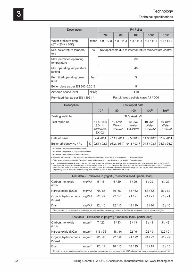
Description P4 Pellet
701) 80 100 1002) 1053)
Water pressure drop (ΔT = 20 K / 10K)
mbar 5,0 / 12,8 4,8 / 14,3 4,3 / 14,3 4,3 / 14,3 4,3 / 14,3
Min. boiler return tempera‐ture
°C Not applicable due to internal return temperature control
Max. permitted operatingtemperature
80
Min. operating temperaturesetting
40
Permitted operating pres‐sure
bar 3
Boiler class as per EN 303-5:2012 5
Airborne sound level dB(A) < 70
Permitted fuel as per EN 14961 1) Part 2: Wood pellets class A1 / D06
Description Test report data
701) 80 100 1002) 1053)
Testing institute TÜV Austria5)
Test report no. 14-U-188/SD; 14-
UW/Wels-EX-024
10-UW/Wels-
EX242/46)
10-UW/Wels-
EX-242/1
10-UW/Wels-
EX-242/56)
10-UW/Wels-
EX-242/2
Date of issue 2.4.2014 27.11.2011 9.5.2011 14.3.2012 11.5.2011
Boiler efficiency NL / PL % 92,7 / 92,7 93,2 / 93,7 94,3 / 93,7 94,3 / 93,7 94,3 / 93,71.P4 Pellet 70 is only available in France2.P4 Pellet 100 (99kW) is only available in UK3.P4 Pellet 105 is only available in Germany4.Detailed information on the fuel is included in the operating instructions, in the section on "Permitted fuels“5.TÜV Austria Services GmbH, Geschäftsbereich Umweltschutz, Am Thalbach 15, A-4600 Thalheim/Wels6.As per ÖNORM / DIN EN 303-5, Section 5.1.3 type test: for a boiler from a range with a consistent structure it is sufficient, if the ratio of
nominal heat output from the largest to the smallest boiler ≤ 2 : 1, to carry out the tests with the smallest and the largest boilers. The boilermanufacturer must ensure that all boilers, including those that have not been tested in the range, whose values have been determineddepending on the nominal heat output by interpolation, fulfil the requirements of the norm.
Test data – Emissions in [mg/MJ] 1) (nominal load / partial load)
Carbon monoxide(CO)
mg/MJ 5 / 15 6 / 29 6 / 29 6 / 29 6 / 29
Nitrous oxide (NOx) mg/MJ 79 / 65 80 / 62 83 / 62 83 / 62 83 / 62
Organic hydrocarbons(OGC)
mg/MJ <2 / <2 <2 / <1 <1 / <1 <1 / <1 <1 / <1
Dust mg/MJ 12 / 10 12 / 10 13 / 10 13 / 10 13 / 101.The pollutant concentration is specified as a mass based on the energy content of the fuel fed to the combustion system in mg/MJ
Test data – Emissions in [mg/m3] 1) (nominal load / partial load)
Carbon monoxide(CO)
mg/m³ 7 / 22 8 / 43 8 / 43 8 / 43 8 / 43
Nitrous oxide (NOx) mg/m³ 116 / 95 118 / 91 122 / 91 122 / 91 122 / 91
Organic hydrocarbons(OGC)
mg/m³ <2 / <3 <2 / <2 <1 / <2 <1 / <2 <1 / <2
Dust mg/m³ 17 / 14 18 / 15 18 / 15 18 / 15 18 / 151.Emissions values based on dry flue gas at standard temperature and pressure (0°C, 1013 mbar) with a volume content of oxygen of 13%
3 TechnologyTechnical specifications
22 Froling GesmbH | A-4710 Grieskirchen, Industriestraße 12 | www.froeling.com
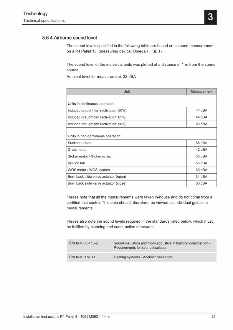
3.6.4 Airborne sound levelThe sound levels specified in the following table are based on a sound measurementon a P4 Pellet 15. (measuring device: Omega HHSL 1) The sound level of the individual units was plotted at a distance of 1 m from the soundsource.Ambient level for measurement: 32 dBA
Unit Measurement
Units in continuous operation:
Induced draught fan (activation: 50%) 41 dBA
Induced draught fan (activation: 65%) 44 dBA
Induced draught fan (activation: 90%) 50 dBA
Units in non-continuous operation:
Suction turbine 68 dBA
Grate motor 42 dBA
Stoker motor / Stoker screw 33 dBA
Ignition fan 53 dBA
WOS motor / WOS system 60 dBA
Burn back slide valve actuator (open) 34 dBA
Burn back slide valve actuator (close) 50 dBA
Please note that all the measurements were taken in-house and do not come from acertified test centre. This data should, therefore, be viewed as individual guidelinemeasurements. Please also note the sound levels required in the standards listed below, which mustbe fulfilled by planning and construction measures:
ÖNORM B 8115-2 Sound insulation and room acoustics in building construction -Requirements for sound insulation
ÖNORM H 5190 Heating systems - Acoustic insulation
Technology 3Technical specifications
Installation Instructions P4 Pellet 8 - 105 | M0931114_en 23
4 Assembly
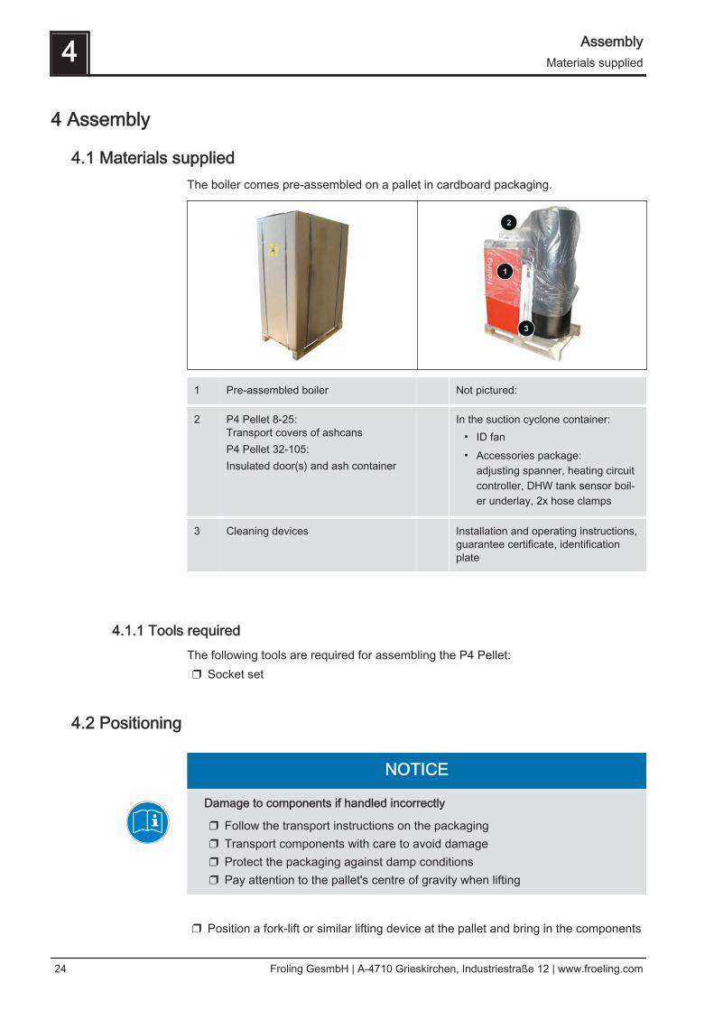
4.1 Materials suppliedThe boiler comes pre-assembled on a pallet in cardboard packaging.
1 Pre-assembled boiler Not pictured:
2 P4 Pellet 8-25: Transport covers of ashcansP4 Pellet 32-105:Insulated door(s) and ash container
In the suction cyclone container:▪ ID fan▪ Accessories package:
adjusting spanner, heating circuitcontroller, DHW tank sensor boil‐er underlay, 2x hose clamps
3 Cleaning devices Installation and operating instructions,guarantee certificate, identificationplate
4.1.1 Tools requiredThe following tools are required for assembling the P4 Pellet:❒ Socket set
4.2 Positioning
NOTICE
Damage to components if handled incorrectly
❒ Follow the transport instructions on the packaging❒ Transport components with care to avoid damage❒ Protect the packaging against damp conditions❒ Pay attention to the pallet's centre of gravity when lifting
❒ Position a fork-lift or similar lifting device at the pallet and bring in the components
4 AssemblyMaterials supplied
24 Froling GesmbH | A-4710 Grieskirchen, Industriestraße 12 | www.froeling.com
If the boiler cannot be brought in on the pallet:❒ Remove the cardboard and remove the boiler from the pallet
⇨ See "Remove boiler from pallet" [page 26] If you need to dismantle the boiler to bring it in:❒ Dismantle the components of the boiler until it can be brought in
⇨ See "Dismantling for location where positioning is difficult" [page 29]
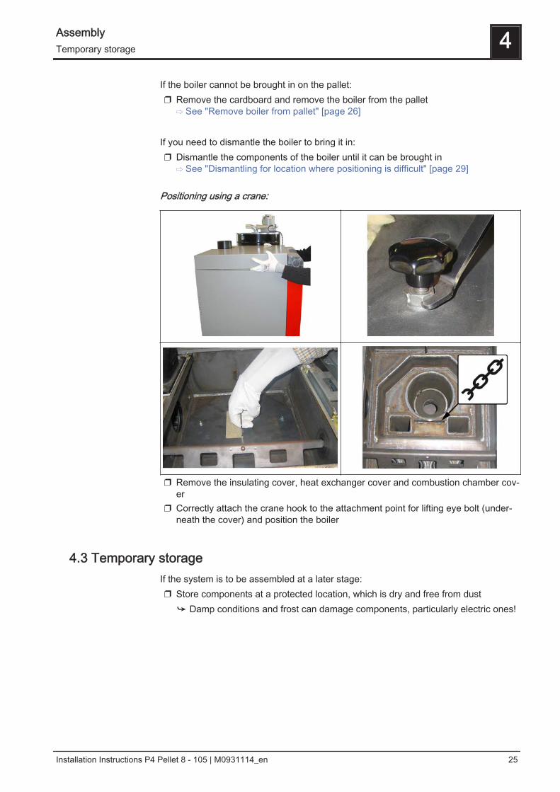
Positioning using a crane:
❒ Remove the insulating cover, heat exchanger cover and combustion chamber cov‐er
❒ Correctly attach the crane hook to the attachment point for lifting eye bolt (under‐neath the cover) and position the boiler
4.3 Temporary storageIf the system is to be assembled at a later stage:❒ Store components at a protected location, which is dry and free from dust
➥ Damp conditions and frost can damage components, particularly electric ones!
Assembly 4Temporary storage
Installation Instructions P4 Pellet 8 - 105 | M0931114_en 25
4.4 Setting up in the boiler room
4.4.1 Remove boiler from pallet
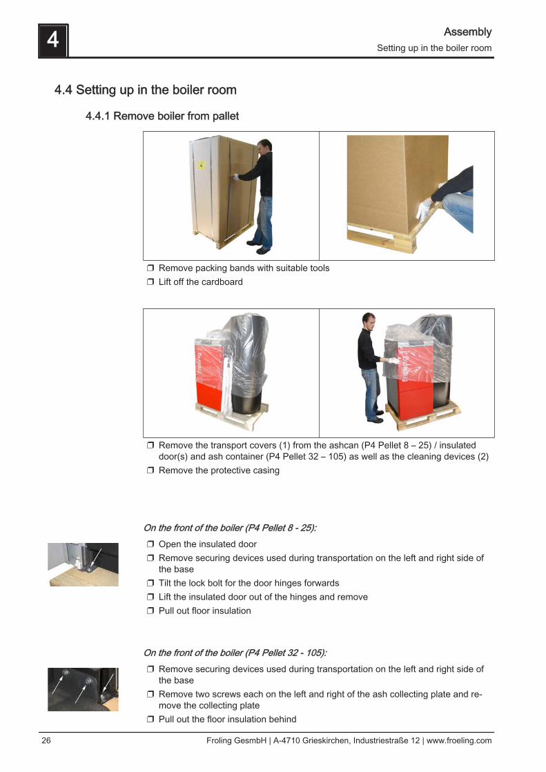
❒ Remove packing bands with suitable tools❒ Lift off the cardboard
❒ Remove the transport covers (1) from the ashcan (P4 Pellet 8 – 25) / insulateddoor(s) and ash container (P4 Pellet 32 – 105) as well as the cleaning devices (2)
❒ Remove the protective casing
On the front of the boiler (P4 Pellet 8 - 25):❒ Open the insulated door❒ Remove securing devices used during transportation on the left and right side of
the base❒ Tilt the lock bolt for the door hinges forwards❒ Lift the insulated door out of the hinges and remove❒ Pull out floor insulation
On the front of the boiler (P4 Pellet 32 - 105):❒ Remove securing devices used during transportation on the left and right side of
the base❒ Remove two screws each on the left and right of the ash collecting plate and re‐
move the collecting plate❒ Pull out the floor insulation behind
4 AssemblySetting up in the boiler room
26 Froling GesmbH | A-4710 Grieskirchen, Industriestraße 12 | www.froeling.com

At the back of the boiler:❒ Remove securing devices used during transportation on the left and right side of
the base ❒ Lift boiler off pallet
TIP: Use Froling’s KHV 1400 boiler lifting system to help remove the pallet!
4.4.2 Moving the boiler in the boiler room❒ Position a fork-lift or similar lifting device with a suitable load-bearing capacity at
the base frame❒ Lift and transport to the intended position in the installation room
➥ Observe the minimum distances in the boiler room.
Assembly 4Setting up in the boiler room
Installation Instructions P4 Pellet 8 - 105 | M0931114_en 27
4.4.3 Minimum distances in the boiler room▪ The system should generally be set up so that it is accessible from all sides allow‐
ing quick and easy maintenance.▪ Regional regulations regarding necessary maintenance areas for inspecting the
chimney should be observed in addition to the specified minimum distances!▪ Observe the applicable standards and regulations when setting up the system.▪ Observe additional standards for noise protection
(ÖNORM H 5190 - Noise protection measures)
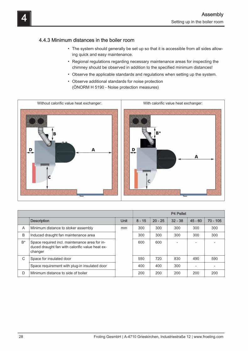
Without calorific value heat exchanger: With calorific value heat exchanger:
P4 Pellet
Description Unit 8 - 15 20 - 25 32 - 38 45 - 60 70 - 105
A Minimum distance to stoker assembly mm 300 300 300 300 300
B Induced draught fan maintenance area 300 300 300 300 300
B* Space required incl. maintenance area for in‐duced draught fan with calorific value heat ex‐changer
600 600 - - -
C Space for insulated door 550 720 830 490 590
Space requirement with plug-in insulated door 400 400 300 - -
D Minimum distance to side of boiler 200 200 200 200 200
4 AssemblySetting up in the boiler room
28 Froling GesmbH | A-4710 Grieskirchen, Industriestraße 12 | www.froeling.com
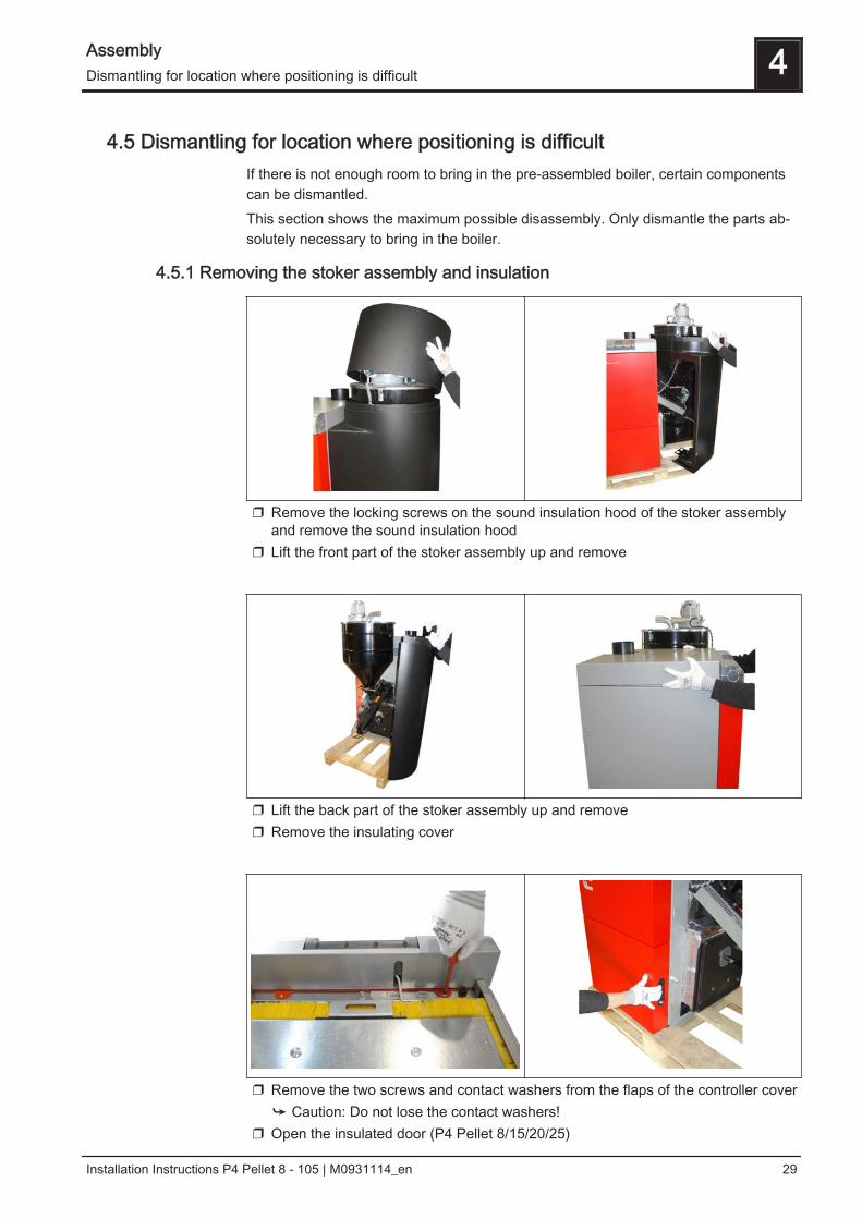
4.5 Dismantling for location where positioning is difficultIf there is not enough room to bring in the pre-assembled boiler, certain componentscan be dismantled.This section shows the maximum possible disassembly. Only dismantle the parts ab‐solutely necessary to bring in the boiler.
4.5.1 Removing the stoker assembly and insulation
❒ Remove the locking screws on the sound insulation hood of the stoker assemblyand remove the sound insulation hood
❒ Lift the front part of the stoker assembly up and remove
❒ Lift the back part of the stoker assembly up and remove❒ Remove the insulating cover
❒ Remove the two screws and contact washers from the flaps of the controller cover➥ Caution: Do not lose the contact washers!
❒ Open the insulated door (P4 Pellet 8/15/20/25)
Assembly 4Dismantling for location where positioning is difficult
Installation Instructions P4 Pellet 8 - 105 | M0931114_en 29
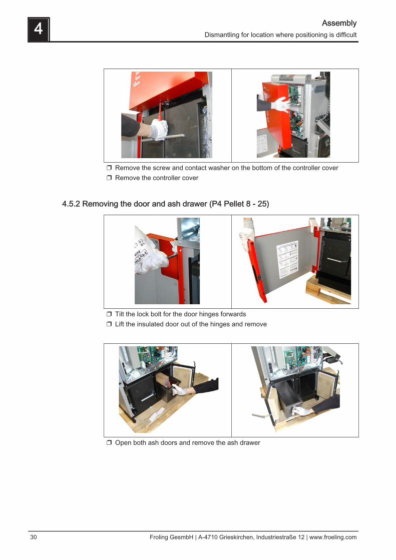
❒ Remove the screw and contact washer on the bottom of the controller cover❒ Remove the controller cover
4.5.2 Removing the door and ash drawer (P4 Pellet 8 - 25)
❒ Tilt the lock bolt for the door hinges forwards❒ Lift the insulated door out of the hinges and remove
❒ Open both ash doors and remove the ash drawer
4 AssemblyDismantling for location where positioning is difficult
30 Froling GesmbH | A-4710 Grieskirchen, Industriestraße 12 | www.froeling.com
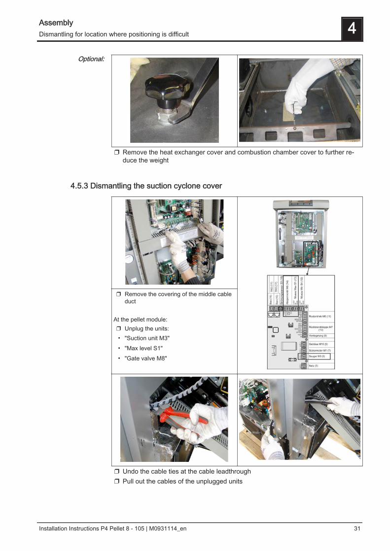
❒ Remove the heat exchanger cover and combustion chamber cover to further re‐duce the weight
4.5.3 Dismantling the suction cyclone cover
❒ Remove the covering of the middle cableduct
At the pellet module:❒ Unplug the units:▪ "Suction unit M3"▪ "Max level S1"▪ "Gate valve M8"
❒ Undo the cable ties at the cable leadthrough❒ Pull out the cables of the unplugged units
Optional:
Assembly 4Dismantling for location where positioning is difficult
Installation Instructions P4 Pellet 8 - 105 | M0931114_en 31
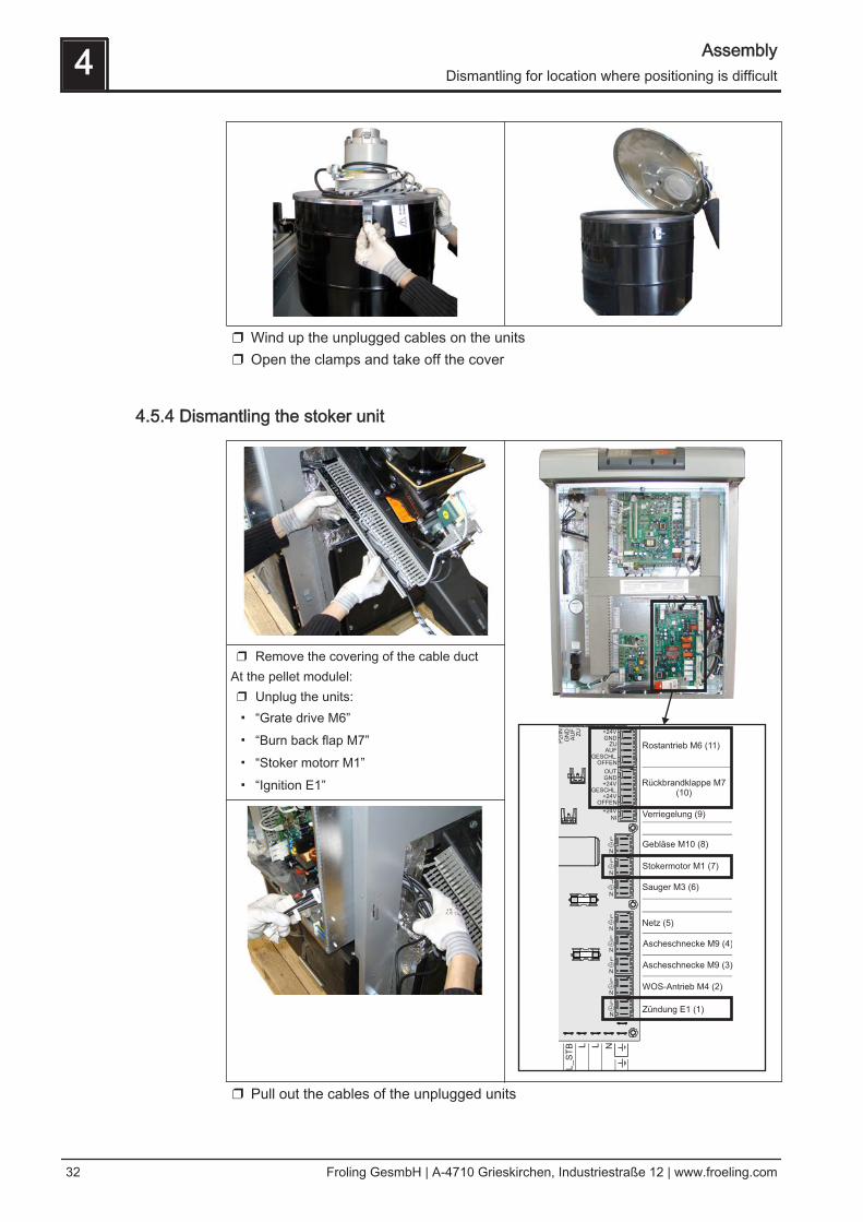
❒ Wind up the unplugged cables on the units❒ Open the clamps and take off the cover
4.5.4 Dismantling the stoker unit
❒ Remove the covering of the cable ductAt the pellet modulel:❒ Unplug the units:▪ “Grate drive M6”▪ “Burn back flap M7”▪ “Stoker motorr M1”▪ “Ignition E1”
❒ Pull out the cables of the unplugged units
4 AssemblyDismantling for location where positioning is difficult
32 Froling GesmbH | A-4710 Grieskirchen, Industriestraße 12 | www.froeling.com
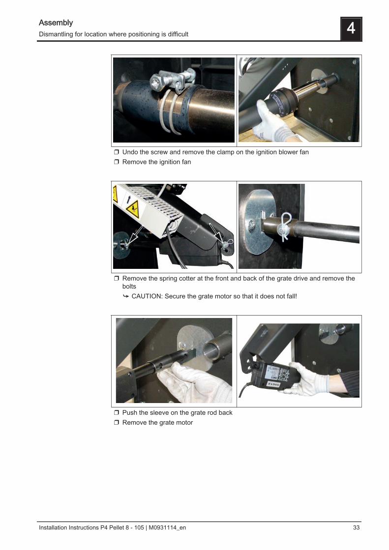
❒ Undo the screw and remove the clamp on the ignition blower fan❒ Remove the ignition fan
❒ Remove the spring cotter at the front and back of the grate drive and remove thebolts➥ CAUTION: Secure the grate motor so that it does not fall!
❒ Push the sleeve on the grate rod back❒ Remove the grate motor
Assembly 4Dismantling for location where positioning is difficult
Installation Instructions P4 Pellet 8 - 105 | M0931114_en 33
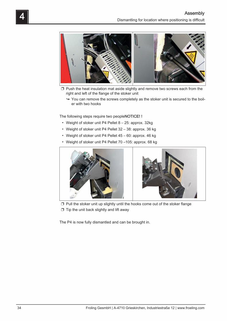
❒ Push the heat insulation mat aside slightly and remove two screws each from theright and left of the flange of the stoker unit➥ You can remove the screws completely as the stoker unit is secured to the boil‐
er with two hooks The following steps require two peopleNOTICE! !▪ Weight of stoker unit P4 Pellet 8 – 25: approx. 32kg▪ Weight of stoker unit P4 Pellet 32 – 38: approx. 36 kg▪ Weight of stoker unit P4 Pellet 45 – 60: approx. 46 kg▪ Weight of stoker unit P4 Pellet 70 –105: approx. 68 kg
❒ Pull the stoker unit up slightly until the hooks come out of the stoker flange❒ Tip the unit back slightly and lift away
The P4 is now fully dismantled and can be brought in.
4 AssemblyDismantling for location where positioning is difficult
34 Froling GesmbH | A-4710 Grieskirchen, Industriestraße 12 | www.froeling.com
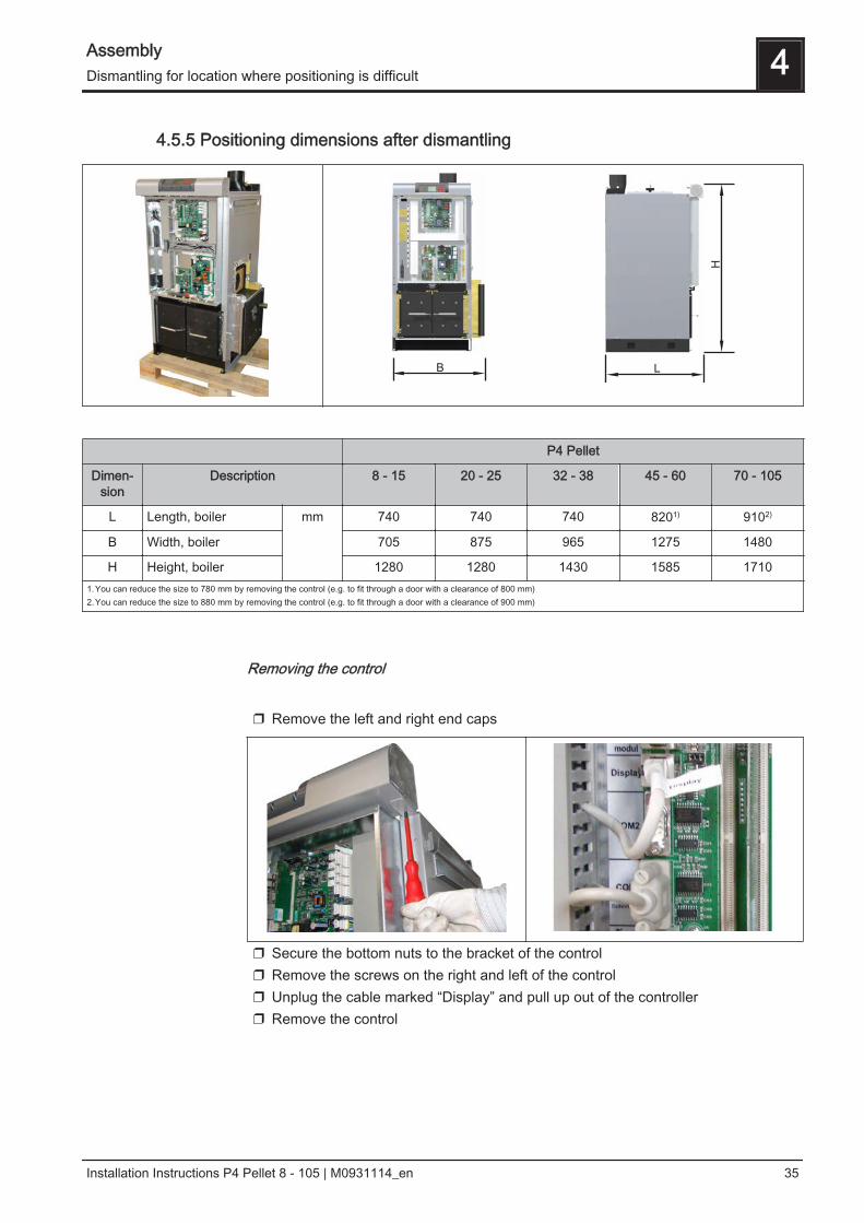
4.5.5 Positioning dimensions after dismantling
P4 Pellet
Dimen‐sion
Description 8 - 15 20 - 25 32 - 38 45 - 60 70 - 105
L Length, boiler mm 740 740 740 8201) 9102)
B Width, boiler 705 875 965 1275 1480
H Height, boiler 1280 1280 1430 1585 17101.You can reduce the size to 780 mm by removing the control (e.g. to fit through a door with a clearance of 800 mm)2.You can reduce the size to 880 mm by removing the control (e.g. to fit through a door with a clearance of 900 mm)
Removing the control
❒ Remove the left and right end caps
❒ Secure the bottom nuts to the bracket of the control❒ Remove the screws on the right and left of the control❒ Unplug the cable marked “Display” and pull up out of the controller❒ Remove the control
Assembly 4Dismantling for location where positioning is difficult
Installation Instructions P4 Pellet 8 - 105 | M0931114_en 35
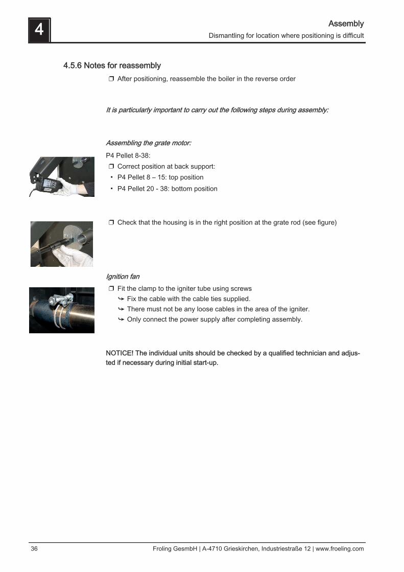
4.5.6 Notes for reassembly❒ After positioning, reassemble the boiler in the reverse order
It is particularly important to carry out the following steps during assembly:
Assembling the grate motor:
P4 Pellet 8-38:❒ Correct position at back support:▪ P4 Pellet 8 – 15: top position▪ P4 Pellet 20 - 38: bottom position
❒ Check that the housing is in the right position at the grate rod (see figure)
Ignition fan❒ Fit the clamp to the igniter tube using screws
➥ Fix the cable with the cable ties supplied.➥ There must not be any loose cables in the area of the igniter.➥ Only connect the power supply after completing assembly.
NOTICE! The individual units should be checked by a qualified technician and adjus‐ted if necessary during initial start-up.
4 AssemblyDismantling for location where positioning is difficult
36 Froling GesmbH | A-4710 Grieskirchen, Industriestraße 12 | www.froeling.com
4.6 Assembling the pellet boiler
4.6.1 Before Installation
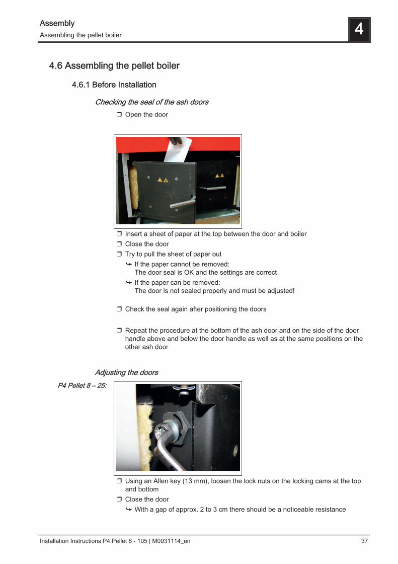
Checking the seal of the ash doors❒ Open the door
❒ Insert a sheet of paper at the top between the door and boiler❒ Close the door❒ Try to pull the sheet of paper out
➥ If the paper cannot be removed:The door seal is OK and the settings are correct
➥ If the paper can be removed:The door is not sealed properly and must be adjusted!
❒ Check the seal again after positioning the doors ❒ Repeat the procedure at the bottom of the ash door and on the side of the door
handle above and below the door handle as well as at the same positions on theother ash door
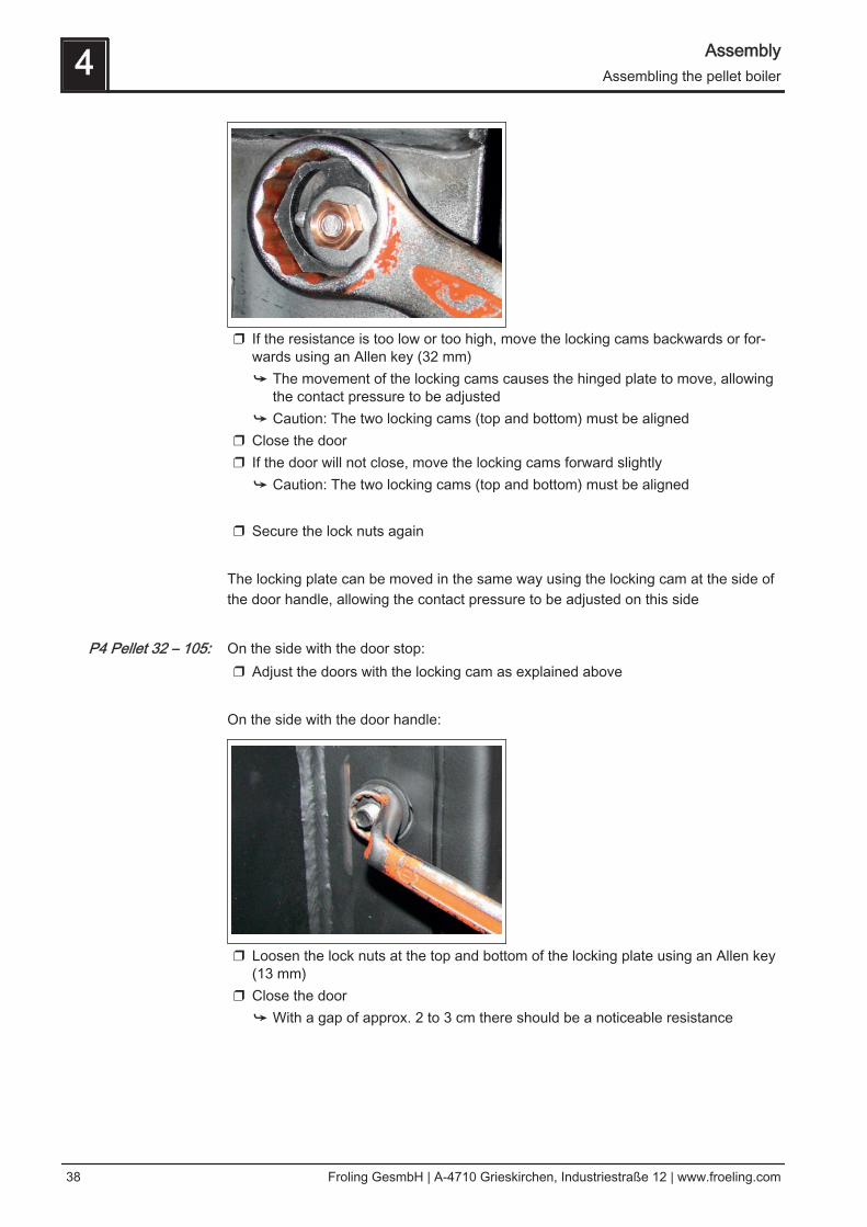
Adjusting the doors
❒ Using an Allen key (13 mm), loosen the lock nuts on the locking cams at the topand bottom
❒ Close the door➥ With a gap of approx. 2 to 3 cm there should be a noticeable resistance
P4 Pellet 8 – 25:
Assembly 4Assembling the pellet boiler
Installation Instructions P4 Pellet 8 - 105 | M0931114_en 37
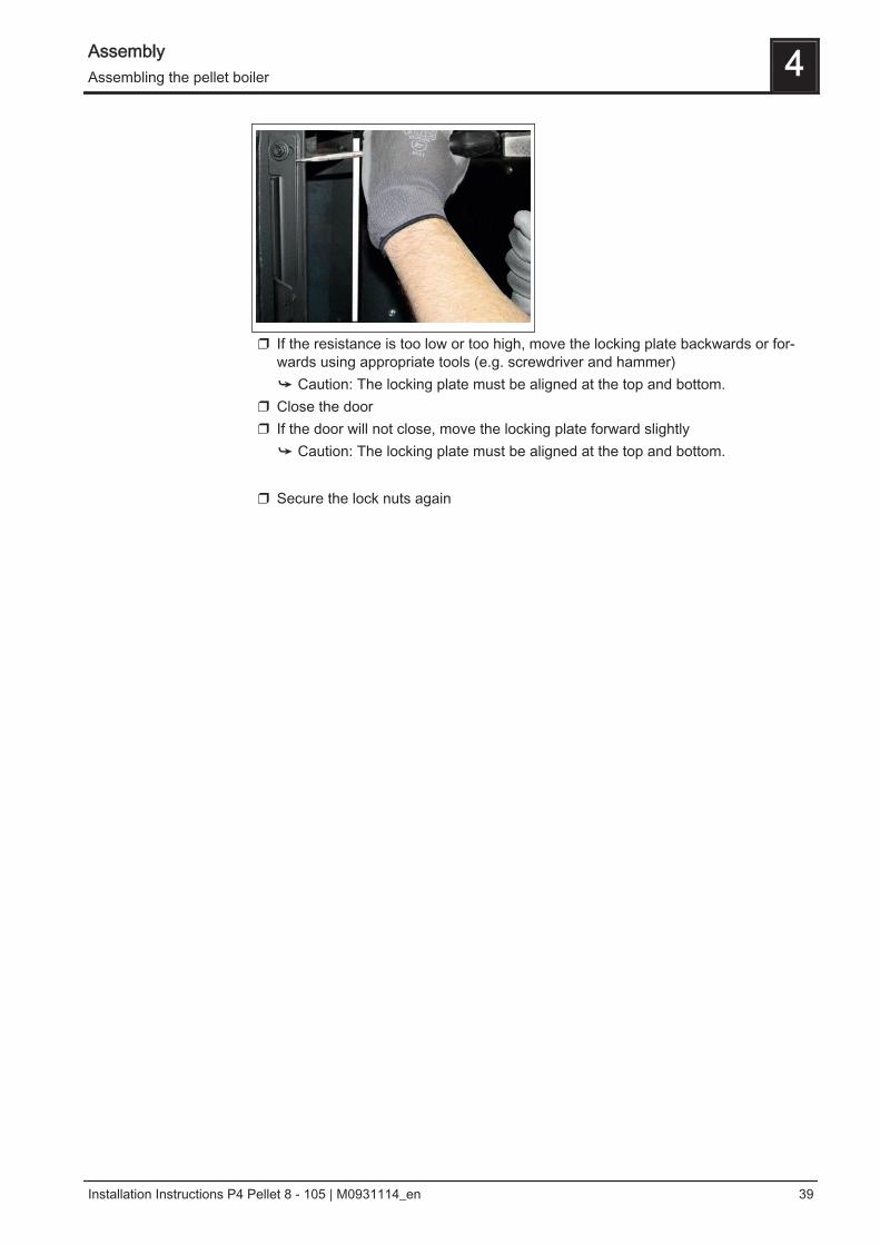
❒ If the resistance is too low or too high, move the locking cams backwards or for‐wards using an Allen key (32 mm)➥ The movement of the locking cams causes the hinged plate to move, allowing
the contact pressure to be adjusted➥ Caution: The two locking cams (top and bottom) must be aligned
❒ Close the door❒ If the door will not close, move the locking cams forward slightly
➥ Caution: The two locking cams (top and bottom) must be aligned ❒ Secure the lock nuts again
The locking plate can be moved in the same way using the locking cam at the side ofthe door handle, allowing the contact pressure to be adjusted on this side On the side with the door stop:❒ Adjust the doors with the locking cam as explained above
On the side with the door handle:
❒ Loosen the lock nuts at the top and bottom of the locking plate using an Allen key(13 mm)
❒ Close the door➥ With a gap of approx. 2 to 3 cm there should be a noticeable resistance
P4 Pellet 32 – 105:
4 AssemblyAssembling the pellet boiler
38 Froling GesmbH | A-4710 Grieskirchen, Industriestraße 12 | www.froeling.com
❒ If the resistance is too low or too high, move the locking plate backwards or for‐wards using appropriate tools (e.g. screwdriver and hammer)➥ Caution: The locking plate must be aligned at the top and bottom.
❒ Close the door❒ If the door will not close, move the locking plate forward slightly
➥ Caution: The locking plate must be aligned at the top and bottom. ❒ Secure the lock nuts again
Assembly 4Assembling the pellet boiler
Installation Instructions P4 Pellet 8 - 105 | M0931114_en 39
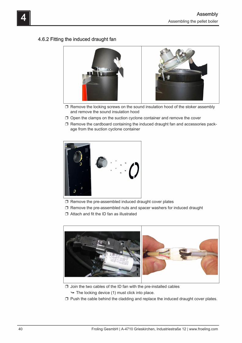
4.6.2 Fitting the induced draught fan
❒ Remove the locking screws on the sound insulation hood of the stoker assemblyand remove the sound insulation hood
❒ Open the clamps on the suction cyclone container and remove the cover❒ Remove the cardboard containing the induced draught fan and accessories pack‐
age from the suction cyclone container
❒ Remove the pre-assembled induced draught cover plates❒ Remove the pre-assembled nuts and spacer washers for induced draught❒ Attach and fit the ID fan as illustrated
❒ Join the two cables of the ID fan with the pre-installed cables➥ The locking device (1) must click into place.
❒ Push the cable behind the cladding and replace the induced draught cover plates.
4 AssemblyAssembling the pellet boiler
40 Froling GesmbH | A-4710 Grieskirchen, Industriestraße 12 | www.froeling.com
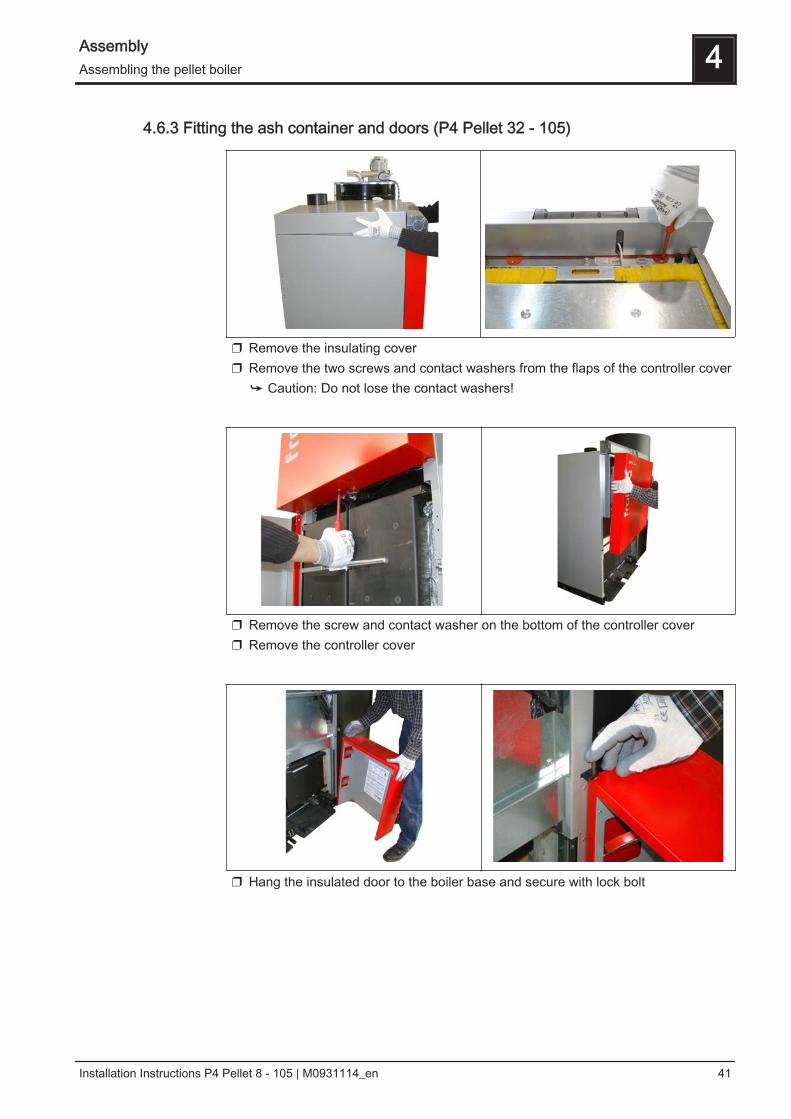
4.6.3 Fitting the ash container and doors (P4 Pellet 32 - 105)
❒ Remove the insulating cover❒ Remove the two screws and contact washers from the flaps of the controller cover
➥ Caution: Do not lose the contact washers!
❒ Remove the screw and contact washer on the bottom of the controller cover❒ Remove the controller cover
❒ Hang the insulated door to the boiler base and secure with lock bolt
Assembly 4Assembling the pellet boiler
Installation Instructions P4 Pellet 8 - 105 | M0931114_en 41
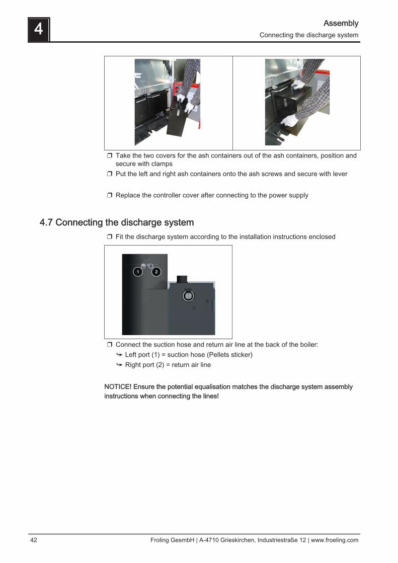
❒ Take the two covers for the ash containers out of the ash containers, position andsecure with clamps
❒ Put the left and right ash containers onto the ash screws and secure with lever ❒ Replace the controller cover after connecting to the power supply
4.7 Connecting the discharge system ❒ Fit the discharge system according to the installation instructions enclosed
❒ Connect the suction hose and return air line at the back of the boiler:➥ Left port (1) = suction hose (Pellets sticker)➥ Right port (2) = return air line
NOTICE! Ensure the potential equalisation matches the discharge system assemblyinstructions when connecting the lines!
4 AssemblyConnecting the discharge system
42 Froling GesmbH | A-4710 Grieskirchen, Industriestraße 12 | www.froeling.com
4.8 Power connection
DANGER
When working on electrical components:
Risk of electrocution!
When work is carried out on electrical components:❒ Only have work carried out by a qualified electrician❒ Observe the applicable standards and regulations
➥ Work must not be carried out on electrical components by unauthorisedpersons
❒ Flexible sheathed cable must be used for the wiring; this must be of the correct
size to comply with applicable regional standards and regulations.❒ The power supply line (mains connection) must be fitted with a C16A fuse by the
customer.
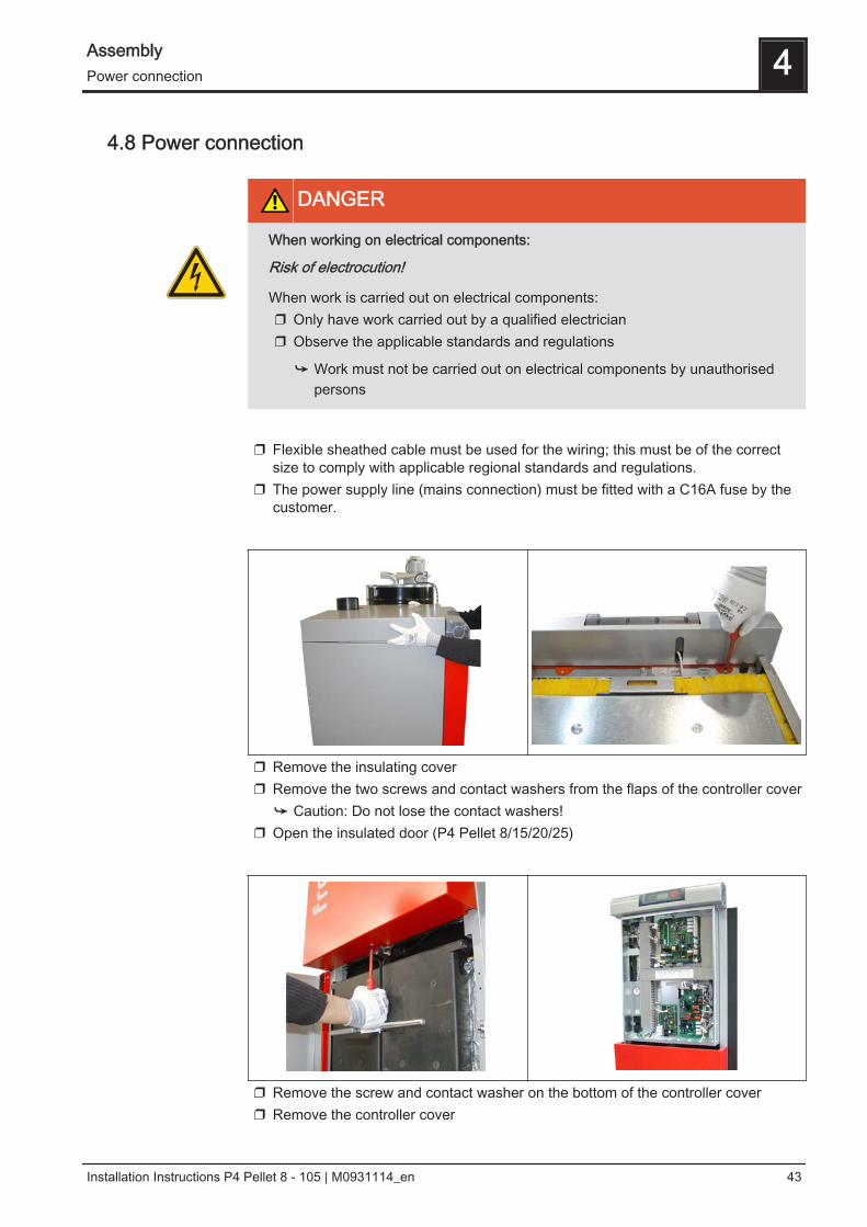
❒ Remove the insulating cover❒ Remove the two screws and contact washers from the flaps of the controller cover
➥ Caution: Do not lose the contact washers!❒ Open the insulated door (P4 Pellet 8/15/20/25)
❒ Remove the screw and contact washer on the bottom of the controller cover❒ Remove the controller cover
Assembly 4Power connection
Installation Instructions P4 Pellet 8 - 105 | M0931114_en 43
❒ Wire the connections in accordance with the circuit diagram➥ For circuit diagrams see operating instructions for "Lambdatronic P 3200"
❒ To reassemble the controller cover and insulating cover, perform the disassembly
steps in the reverse order
4.8.1 Information on circulating pumps
NOTICE
According to 2012/622/EU external, wet running circulating pumps must complywith the following limit values of the Energy Efficiency Index (EEI):
- Effective from 01/01/2013: Wet running circulating pumps with EEI ≤ 0.27- Effective from 08/01/2015: Wet running circulating pumps with EEI ≤ 0.23
Only high efficiency pumps with a connection option for a control signal (PDM / 0-10V)should be connected to speed-controlled pump outputs (pump 1 on the core moduleand pump outputs on the hydraulic module). In this case, the control line is connectedto the corresponding PDM outputs of the boards. Observe the connection instructionsin the boiler controller documentation!
CAUTION
When using high efficiency pumps without an additional control line at speed-con‐trolled pump outputs:
Malfunctions of the boiler, the pump and the hydraulic system may occur!
Therefore:❒ Do not connect EC motor pumps without a control line to the speed-controlled
pump outputs of the boards.➥ Only use special high efficiency pumps with a connection option for a con‐
trol line (PDM/0-10V)!➥ Observe the additional instructions and information on board outputs in the
operation instructions for the boiler controller.
4 AssemblyPower connection
44 Froling GesmbH | A-4710 Grieskirchen, Industriestraße 12 | www.froeling.com
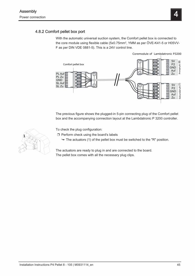
4.8.2 Comfort pellet box portWith the automatic universal suction system, the Comfort pellet box is connected tothe core module using flexible cable (5x0.75mm2, YMM as per ÖVE-K41-5 or H05VV-F as per DIN VDE 0881-5). This is a 24V control line.
The previous figure shows the plugged-in 5-pin connecting plug of the Comfort pelletbox and the accompanying connection layout at the Lambdatronic P 3200 controller. To check the plug configuration:❒ Perform check using the board's labels
➥ The actuators (1) of the pellet box must be switched to the "R" position. The actuators are ready to plug in and are connected to the board.The pellet box comes with all the necessary plug clips.
1
Assembly 4Power connection
Installation Instructions P4 Pellet 8 - 105 | M0931114_en 45
5 Start-up
5.1 Before commissioning / configuring the boilerThe boiler must be adjusted to the heating system during commissioning.
NOTICE
Optimum efficiency and efficient, low-emission operation can only be guaranteedif the system is set up by trained professionals and the standard factory settingsare observed.
Take the following precautions:❒ Initial startup should be carried out with an authorised installer or with Froling
customer services
❒ Adjust the boiler controller to the system type❒ Apply boiler standard values
NOTICE! The keypad assignment and the steps necessary to modify the parametersare detailed in the operating instructions for the boiler control unit.❒ Check the system pressure of the heating system❒ Check that the heating system is completely vented❒ Check that the safety devices are present and working correctly❒ Check that there is sufficient ventilation in the boiler room❒ Check the seal of the boiler
➥ All doors and inspection openings must be tightly sealed! ❒ Check that drives and actuators are working and turning in the right direction
NOTICE! For how to check the analogue and digital outputs, see the operating instruc‐tions for the boiler controller ❒ Check that the door contact switch is working correctly
NOTICE! For how to check the digital inputs see the operating instructions for the boil‐er controller.
5 Start-upBefore commissioning / configuring the boiler
46 Froling GesmbH | A-4710 Grieskirchen, Industriestraße 12 | www.froeling.com
5.1.1 Setting the "Max level and Min level” sensor
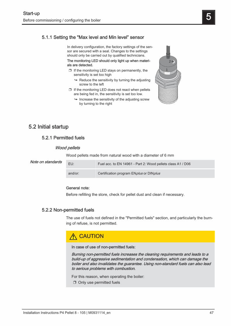
In delivery configuration, the factory settings of the sen‐sor are secured with a seal. Changes to the settingsshould only be carried out by qualified technicians.The monitoring LED should only light up when materi‐als are detected.❒ If the monitoring LED stays on permanently, the
sensitivity is set too high➥ Reduce the sensitivity by turning the adjusting
screw to the left❒ If the monitoring LED does not react when pellets
are being fed in, the sensitivity is set too low.➥ Increase the sensitivity of the adjusting screw
by turning to the right
1
2
5.2 Initial startup
5.2.1 Permitted fuels
Wood pelletsWood pellets made from natural wood with a diameter of 6 mm
EU: Fuel acc. to EN 14961 - Part 2: Wood pellets class A1 / D06
and/or: Certification program ENplus or DINplus
General note:Before refilling the store, check for pellet dust and clean if necessary.
5.2.2 Non-permitted fuelsThe use of fuels not defined in the "Permitted fuels" section, and particularly the burn‐ing of refuse, is not permitted.
CAUTION
In case of use of non-permitted fuels:
Burning non-permitted fuels increases the cleaning requirements and leads to abuild-up of aggressive sedimentation and condensation, which can damage theboiler and also invalidates the guarantee. Using non-standard fuels can also leadto serious problems with combustion.
For this reason, when operating the boiler:❒ Only use permitted fuels
Note on standards
Start-up 5Before commissioning / configuring the boiler
Installation Instructions P4 Pellet 8 - 105 | M0931114_en 47
5.2.3 Heating up for the first time
NOTICE
If condensation escapes during the initial heat-up phase, this does not indicate afault.
❒ Tip: If this occurs, clean up using a cleaning rag.
NOTICE! See boiler controller operating instructions for all the steps necessary to startup for the first time Lambdatronic P 3200
5 Start-upInitial startup
48 Froling GesmbH | A-4710 Grieskirchen, Industriestraße 12 | www.froeling.com
6 Decommissioning
6.1 MothballingThe following measures should be taken if the boiler is to remain out of service forseveral weeks (e.g. during the summer):❒ Clean the boiler thoroughly and close the doors fully
If the boiler is to remain out of service during the winter:❒ Have the system completely drained by a qualified technician
➥ Protection against frost
6.2 DisassemblyTo disassemble the system, follow the steps for assembly in reverse order.
6.3 Disposal❒ Ensure that they are disposed of in an environmentally friendly way in accordance
with waste management regulations.❒ You can separate and clean recyclable materials and send them to a recycling
centre.
Decommissioning 6Mothballing
Installation Instructions P4 Pellet 8 - 105 | M0931114_en 49
7 Appendix
7.1 Addresses
7.1.1 Address of manufacturer
FRÖLINGHeizkessel- und Behälterbau GesmbH Industriestraße 12A-4710 GrieskirchenAUSTRIA TEL 0043 (0)7248 606 0FAX 0043 (0)7248 606 600INTERNET www.froeling.com
7.1.2 Address of the installer
Stamp
7 AppendixAddresses
50 Froling GesmbH | A-4710 Grieskirchen, Industriestraße 12 | www.froeling.com