penstocks, powerhouse and tailrace
TRANSCRIPT

HYDROPOWER
PRESENTATION

HYDROPOWER
PRESENTATION

TOPIC
PENSTOCKS, POWER HOUSE
AND TAIL RACE

ELEMENTS OF HYDRO POWER
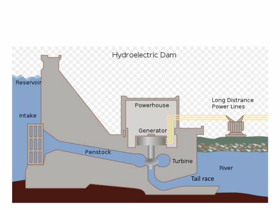
Reservoir
Dam
Intake
Penstock
Power House
Turbine
Generator
Power Line
Transformer
12/17/2014 4BCE/2068/ 71 to 80

12/17/2014 BCE/2068/ 71 to 80 5
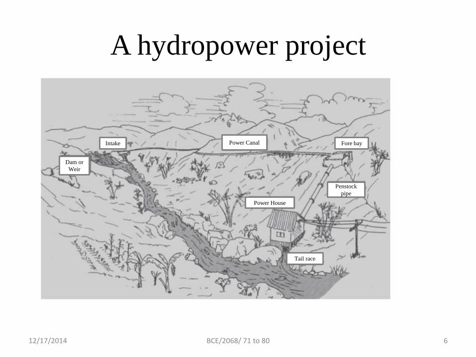
A hydropower project
12/17/2014 BCE/2068/ 71 to 80 6
Dam or
Weir
Intake Power Canal Fore bay
Penstock
pipe
Power House
Tail race
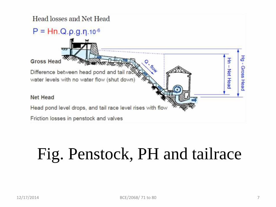
Fig. Penstock, PH and tailrace
12/17/2014 BCE/2068/ 71 to 80 7

12/17/2014 BCE/2068/ 71 to 80 8
PENSTOCK
• Pipe conveying the flow of water from the fore
bay or surge tank to the turbine in the power
house
• Pressurized water conduits
• Designed with least possible loss of head
consistent
12/17/2014 9BCE/2068/ 71 to 80
Types of penstock
• Exposed
• Embedded
• Underground
12/17/2014 BCE/2068/ 71 to 80 10
1. Exposed penstock
• Located above the ground
• Supported by pier or saddle or ring girder
12/17/2014 BCE/2068/ 71 to 80 11
Merits of using Exposed Penstock:-
• Easy to inspect faults and maintain as per
requirement
• Economical in rocky terrain and large diameter
• No need of excavation
• Stability ensured with anchorage
12/17/2014 BCE/2068/ 71 to 80 12

Demerits of Exposed Penstock:-
• Direct exposure to outer environment so
weather affects
• Development of longitudinal stress on account
of supports and anchorages so expansion joints
are necessary
12/17/2014 BCE/2068/ 71 to 80 13

2. Embedded penstock
• Located in a tunnel
12/17/2014 BCE/2068/ 71 to 80 14

3. Underground penstock
• Partially or fully buried
• Supported on the soil in a trench at a depth of
1 m to 1.5 m
12/17/2014 BCE/2068/ 71 to 80 15

Merits of Buried Penstock:-
• Support given by soil so system stable
structurally
• Conservation of natural landscape
• Economical
• Protection from landslide, storm and man
made voilences
12/17/2014 BCE/2068/ 71 to 80 16

Demerits of Buried Penstock:-
• Difficulty in inspection of faults and
maintainance
• Possibility of slides in steep slopes
• High expense for large diameter pipe in rocky
or boulder mixed soil
12/17/2014 BCE/2068/ 71 to 80 17
12/17/2014 BCE/2068/ 71 to 80 18
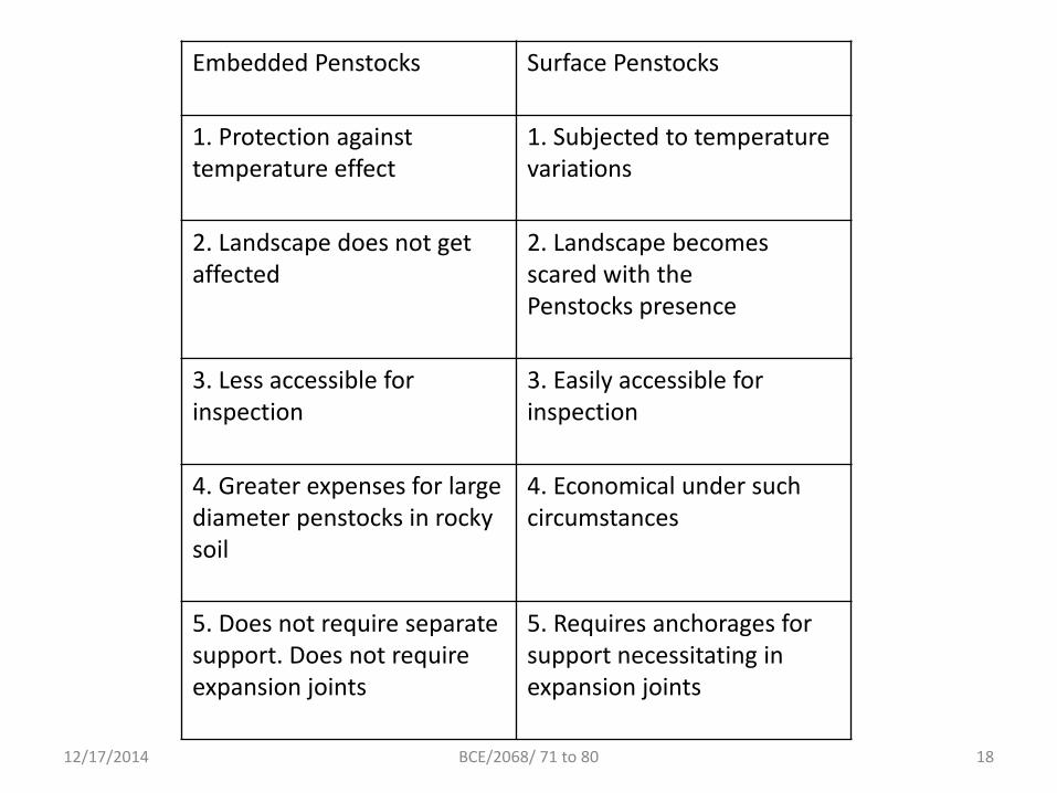
Embedded Penstocks Surface Penstocks
1. Protection against temperature effect
1. Subjected to temperature variations
2. Landscape does not get affected
2. Landscape becomes scared with thePenstocks presence
3. Less accessible for inspection
3. Easily accessible for inspection
4. Greater expenses for large diameter penstocks in rocky soil
4. Economical under such circumstances
5. Does not require separate support. Does not require expansion joints
5. Requires anchorages for support necessitating in expansion joints

• In general, the optimum penstock is as short, straight and steep as practical and has a continuous downward gradient.
• Such characteristics will minimize construction costs and friction loss.
12/17/2014 BCE/2068/ 71 to 80 19
The following are some major factors that must
be considered in selecting a penstock route.
• Accessibility: The route should be accessible to personnel
and equipment required for pipe installation, inspection
and maintenance. In those areas where equipment access
is difficult or impossible; installation and maintenance
must be performed manually.
• Soil Conditions: Soils along the pipline should be
examined to identify rock outcroppings, soft or unstable
soils or other characteristics that would interfere with
penstock installation or damage the penstock.
12/17/2014 BCE/2068/ 71 to 80 20

• Natural or Man-Made Obstructions: These include trees, roadways, buildings, stream crossings, and other features that require special care.
• Gradient: The penstock is best routed to take advantage of the natural downward gradient. If the line cannot be located so as to have a constant downward gradient, an air relief valve or equivalent device is required at every local high point, and a drain valve is required at every local low point.
12/17/2014 BCE/2068/ 71 to 80 21

Penstock alignment
12/17/2014 BCE/2068/ 71 to 80 22

• Penstock alignment:-
• To determine the most economical alignment of a pipeline, the designer must investigate the site and make various layouts on topographic maps.
• He must then estimate material quantities for each layout and evaluate its constructability.
• When making the layouts, the penstock should be located on stable foundation sites such as along a ridge or a bench that has been cut into the mountainside, avoiding of troublesome sites such as underground water courses, landfill, fault zones and potential slide areas is quite important.
• To minimize costly anchors and costly pipe transition sections, vertical bends, horizontal bends and changes in diameter should be combined in a way to have them at the same location. Selection of the penstock alignment at site should be base on the following criteria.
•
•
12/17/2014 BCE/2068/ 71 to 80 23

• Fore bay or surge tank location
• The penstock starts at the fore bay or surge tank, and its location should be chosen to optimize the lengths of headrace and penstock whilst achieving the required power output from the scheme. Penstock pipe is generally more expensive than headrace canal or tunnel therefore in most cases the fore bay or surge tank location should be chosen to give the minimum penstock length. However, sometimes a longer penstock may be economic to avoid the need for the headrace to cross an unstable slope.
• Practical ground slope
• An ideal ground slope for the penstock alignment is between 1:1 and 1:2(V:H). The flatter the ground slope the less economic is the penstock since a longer pipe length is required for a lower head.
• Although a steep slope minimizes the penstock length, it will be difficult to manually lay the penstock, construct support piers and anchor blocks if the slope is greater than 1:1. Therefore, for penstock alignments on slopes steeper than 1:1, the added site installation cost may outweigh the savings made on the pipe costs.
•
• Minimum number of bends
• Bends increase the head loss and require additional anchor blocks. Therefore the selected alignment should be as straight as possible, both in plan and elevation. Note that small bends can be avoided by varying the support pier heights for the exposed section and the trench depth for the buried section.
•12/17/2014 BCE/2068/ 71 to 80 24

• Space for powerhouse area
• The chosen alignment should be such that it is possible to construct a powerhouse at the end of the penstock. A river terrace well above the flood level is ideal for the powerhouse area. A route that is otherwise suitable for the penstock alignment but does not allow for the construction of the power house is inappropriate.
• Stability
• Since the penstock alignment is on steep ground slopes and the pipe is under pressure, it is important for the alignment to be on stable ground. Any ground movement can damage the pipe, support piers and anchor blocks and in case of pipe bursts unstable slopes will cause further erosion and landslides.
• Other site specific conditions
• Apart from the above criteria, there may be other site specific conditions that dictate the penstock alignment. For example, if the alignment crosses a local trail, road, canal, this section should either be buried or high enough above the ground such that people and cattle can walk underneath.
•
12/17/2014 BCE/2068/ 71 to 80 25

• 5.2.4 Penstocks
•
• As mentioned before, a penstock is usually steel or reinforced concrete lined conduit
• that supplied water from the reservoir, forebay or surge tank at the end of a head race
• Version 2 CE IIT, Kharagpur tunnel to the turbines. A penstock is subjected to very high pressure and its design is
• similar to that for pressure vessels and tanks. However, sudden pressure rise due to
• value closure of turbines during sudden load rejection in the electric grid necessitates
• that penstocks be designed for such water hammer pressures as well. Penstocks, at
• their lowermost end meets a controlling value, from where the water is led to the spiral
• casing of the turbine, details of which would be discussed in the next lesson.
• Since penstocks convey water to the turbines and form a part of the hydropower water
• conveyance system, it is necessary that they provide the least possible loss of energy
• head to the flowing water. According to the Bureau of Indian Standards code IS: 11625-
• 1986 “Criteria for hydraulic design of penstocks”, the following losses may be expected
• for a penstock:
• a. Head loss at trash rock
• b. Head loss at intake entrance
• c. Friction losses, and
• d. Other losses as at bends, bifurcations, transitions, values, etc.
• Based on the above losses, the diameter of the penstock pipes have to be fixed, such
• that it results in an overall economy. This is because if the diameter of a penstock is
• increased, for example, the friction losses reduce resulting in a higher head at turbine
• and consequent generations of more power. But this, at the same time, increases the
• cost of the penstock. This leads to the concept of Economic Diameter of Penstock
• which is one such that the annual cost, including cost of power lost due to friction and
• charges of amortization of construction cost, maintenance, operation, etc. is the
• minimum.
12/17/2014 BCE/2068/ 71 to 80 26
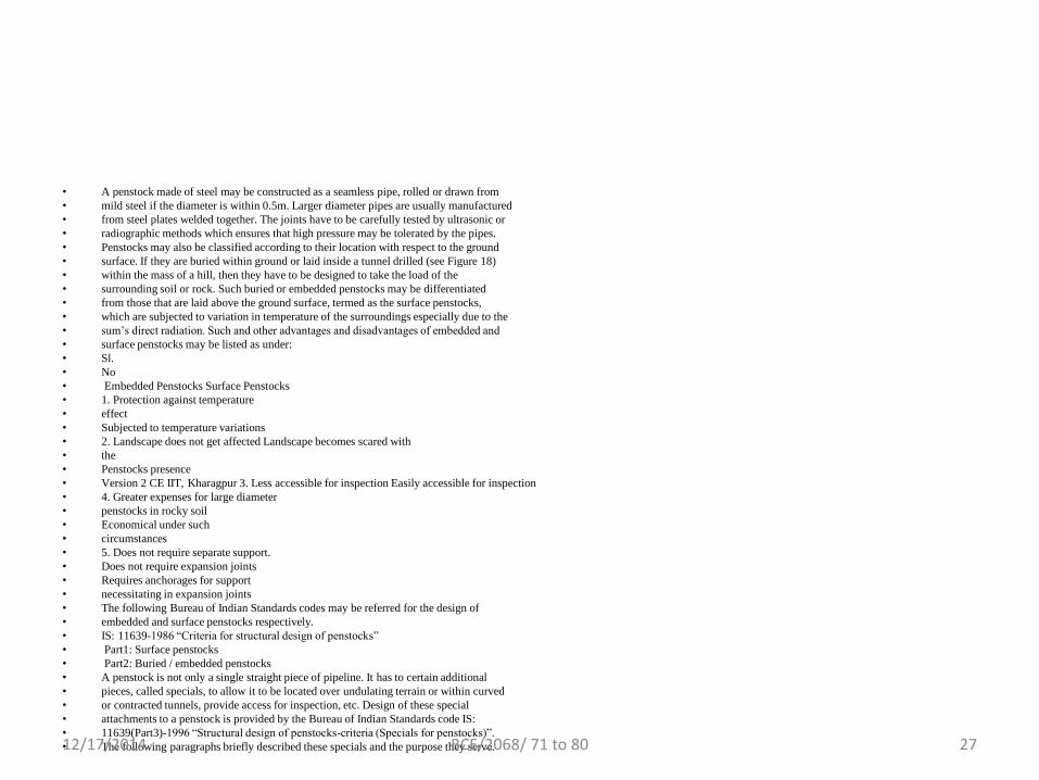
• A penstock made of steel may be constructed as a seamless pipe, rolled or drawn from
• mild steel if the diameter is within 0.5m. Larger diameter pipes are usually manufactured
• from steel plates welded together. The joints have to be carefully tested by ultrasonic or
• radiographic methods which ensures that high pressure may be tolerated by the pipes.
• Penstocks may also be classified according to their location with respect to the ground
• surface. If they are buried within ground or laid inside a tunnel drilled (see Figure 18)
• within the mass of a hill, then they have to be designed to take the load of the
• surrounding soil or rock. Such buried or embedded penstocks may be differentiated
• from those that are laid above the ground surface, termed as the surface penstocks,
• which are subjected to variation in temperature of the surroundings especially due to the
• sum’s direct radiation. Such and other advantages and disadvantages of embedded and
• surface penstocks may be listed as under:
• Sl.
• No
• Embedded Penstocks Surface Penstocks
• 1. Protection against temperature
• effect
• Subjected to temperature variations
• 2. Landscape does not get affected Landscape becomes scared with
• the
• Penstocks presence
• Version 2 CE IIT, Kharagpur 3. Less accessible for inspection Easily accessible for inspection
• 4. Greater expenses for large diameter
• penstocks in rocky soil
• Economical under such
• circumstances
• 5. Does not require separate support.
• Does not require expansion joints
• Requires anchorages for support
• necessitating in expansion joints
• The following Bureau of Indian Standards codes may be referred for the design of
• embedded and surface penstocks respectively.
• IS: 11639-1986 “Criteria for structural design of penstocks”
• Part1: Surface penstocks
• Part2: Buried / embedded penstocks
• A penstock is not only a single straight piece of pipeline. It has to certain additional
• pieces, called specials, to allow it to be located over undulating terrain or within curved
• or contracted tunnels, provide access for inspection, etc. Design of these special
• attachments to a penstock is provided by the Bureau of Indian Standards code IS:
• 11639(Part3)-1996 “Structural design of penstocks-criteria (Specials for penstocks)”.
• The following paragraphs briefly described these specials and the purpose they serve.12/17/2014 BCE/2068/ 71 to 80 27
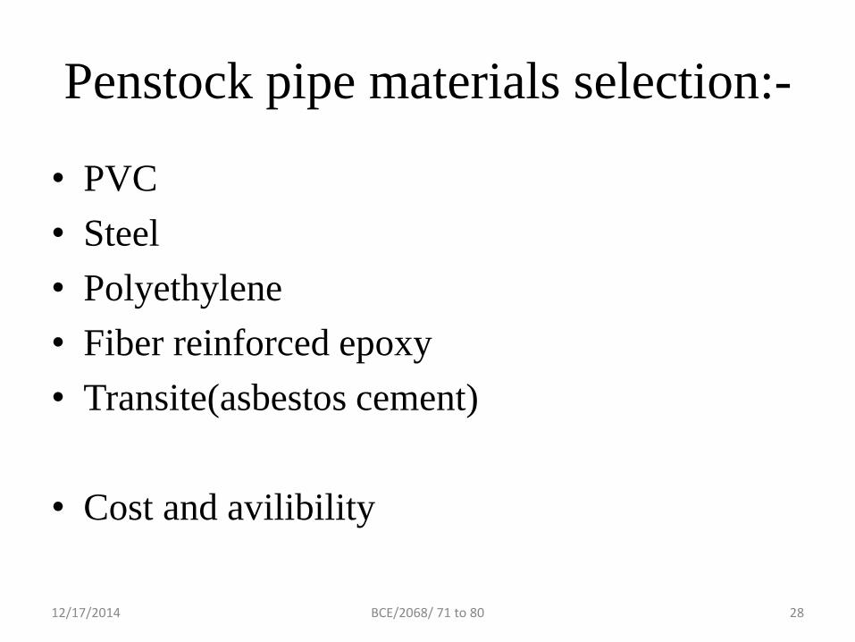
Penstock pipe materials selection:-
• PVC
• Steel
• Polyethylene
• Fiber reinforced epoxy
• Transite(asbestos cement)
• Cost and avilibility
12/17/2014 BCE/2068/ 71 to 80 28

Considerations:-
• Cost
• Availibility
• Physical properties (friction, strength)
• Joining methods and installation limitations
12/17/2014 BCE/2068/ 71 to 80 29
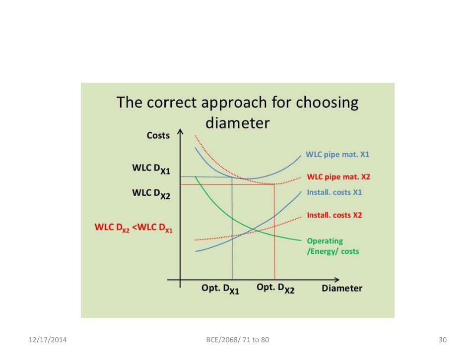
12/17/2014 BCE/2068/ 71 to 80 30

Power House
• A part of the hydropower generation where
power is generated
• Where mechanical, electrical machines and
equipments are integrated
12/17/2014 BCE/2068/ 71 to 80 31

POWER HOUSE & EQUIPMENTS:-
• In the scheme of hydropower the role of power house is to
protect the electromechanical equipment that convert the
potential energy of water into electricity.
• Following are the equipments of power plant:
1.Valve 5.Condensor
2.Turbine 6.Protection System
3.Generator 7.DC emergency Supply
4.Control System 8.Power and current transformer
12/17/2014 32BCE/2068/ 71 to 80
12/17/2014 BCE/2068/ 71 to 80 33
Tail race

12/17/2014 BCE/2068/ 71 to 80 34
Tailraces:-
• After passing through the turbine the water
returns to the river trough a short canal called a
tailrace.
12/17/2014 35BCE/2068/ 71 to 80

12/17/2014 BCE/2068/ 71 to 80 36