perforated & solid cable tray dimensions are in millimeters unless otherwise specified....
TRANSCRIPT
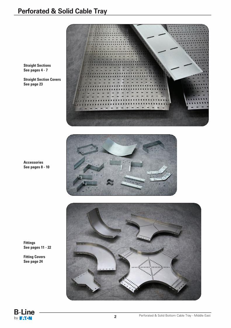
Straight SectionsSee pages 4 - 7
Straight Section CoversSee page 23
AccessoriesSee pages 8 - 10
FittingsSee pages 11 - 22
Fitting CoversSee page 24
Perforated & Solid Bottom Cable Tray - Middle East2
Perforated & Solid Cable Tray
3
Perforated & Solid Cable Tray - Load Data
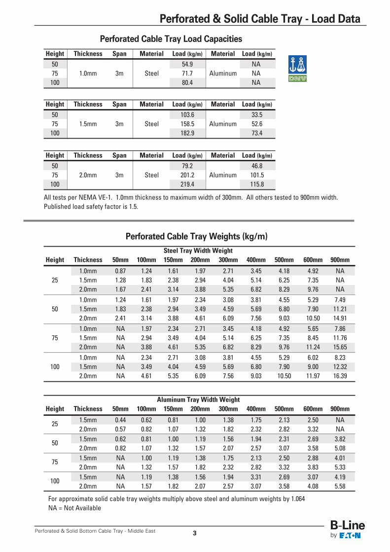
Perforated Cable Tray Weights (kg/m)
Perforated & Solid Bottom Cable Tray - Middle East
Height Thickness Span Material Load (kg/m) Material Load (kg/m)
50 103.6 33.575 1.5mm 3m Steel 158.5 Aluminum 52.6100 182.9 73.4
Height Thickness Span Material Load (kg/m) Material Load (kg/m)
50 79.2 46.875 2.0mm 3m Steel 201.2 Aluminum 101.5100 219.4 115.8
Steel Tray Width WeightHeight Thickness 50mm 100mm 150mm 200mm 300mm 400mm 500mm 600mm 900mm
1.0mm 0.87 1.24 1.61 1.97 2.71 3.45 4.18 4.92 NA25 1.5mm 1.28 1.83 2.38 2.94 4.04 5.14 6.25 7.35 NA
2.0mm 1.67 2.41 3.14 3.88 5.35 6.82 8.29 9.76 NA1.0mm 1.24 1.61 1.97 2.34 3.08 3.81 4.55 5.29 7.49
50 1.5mm 1.83 2.38 2.94 3.49 4.59 5.69 6.80 7.90 11.212.0mm 2.41 3.14 3.88 4.61 6.09 7.56 9.03 10.50 14.911.0mm NA 1.97 2.34 2.71 3.45 4.18 4.92 5.65 7.86
75 1.5mm NA 2.94 3.49 4.04 5.14 6.25 7.35 8.45 11.762.0mm NA 3.88 4.61 5.35 6.82 8.29 9.76 11.24 15.651.0mm NA 2.34 2.71 3.08 3.81 4.55 5.29 6.02 8.23
100 1.5mm NA 3.49 4.04 4.59 5.69 6.80 7.90 9.00 12.322.0mm NA 4.61 5.35 6.09 7.56 9.03 10.50 11.97 16.39
Aluminum Tray Width WeightHeight Thickness 50mm 100mm 150mm 200mm 300mm 400mm 500mm 600mm 900mm
25 1.5mm 0.44 0.62 0.81 1.00 1.38 1.75 2.13 2.50 NA2.0mm 0.57 0.82 1.07 1.32 1.82 2.32 2.82 3.32 NA
50 1.5mm 0.62 0.81 1.00 1.19 1.56 1.94 2.31 2.69 3.822.0mm 0.82 1.07 1.32 1.57 2.07 2.57 3.07 3.58 5.08
75 1.5mm NA 1.00 1.19 1.38 1.75 2.13 2.50 2.88 4.012.0mm NA 1.32 1.57 1.82 2.32 2.82 3.32 3.83 5.33
100 1.5mm NA 1.19 1.38 1.56 1.94 3.31 2.69 3.07 4.192.0mm NA 1.57 1.82 2.07 2.57 3.07 3.58 4.08 5.58
All tests per NEMA VE-1. 1.0mm thickness to maximum width of 300mm. All others tested to 900mm width.Published load safety factor is 1.5.
For approximate solid cable tray weights multiply above steel and aluminum weights by 1.064NA = Not Available
Perforated Cable Tray Load Capacities
Height Thickness Span Material Load (kg/m) Material Load (kg/m)
50 54.9 NA75 1.0mm 3m Steel 71.7 Aluminum NA100 80.4 NA
All dimensions are in millimeters unless otherwise specified.
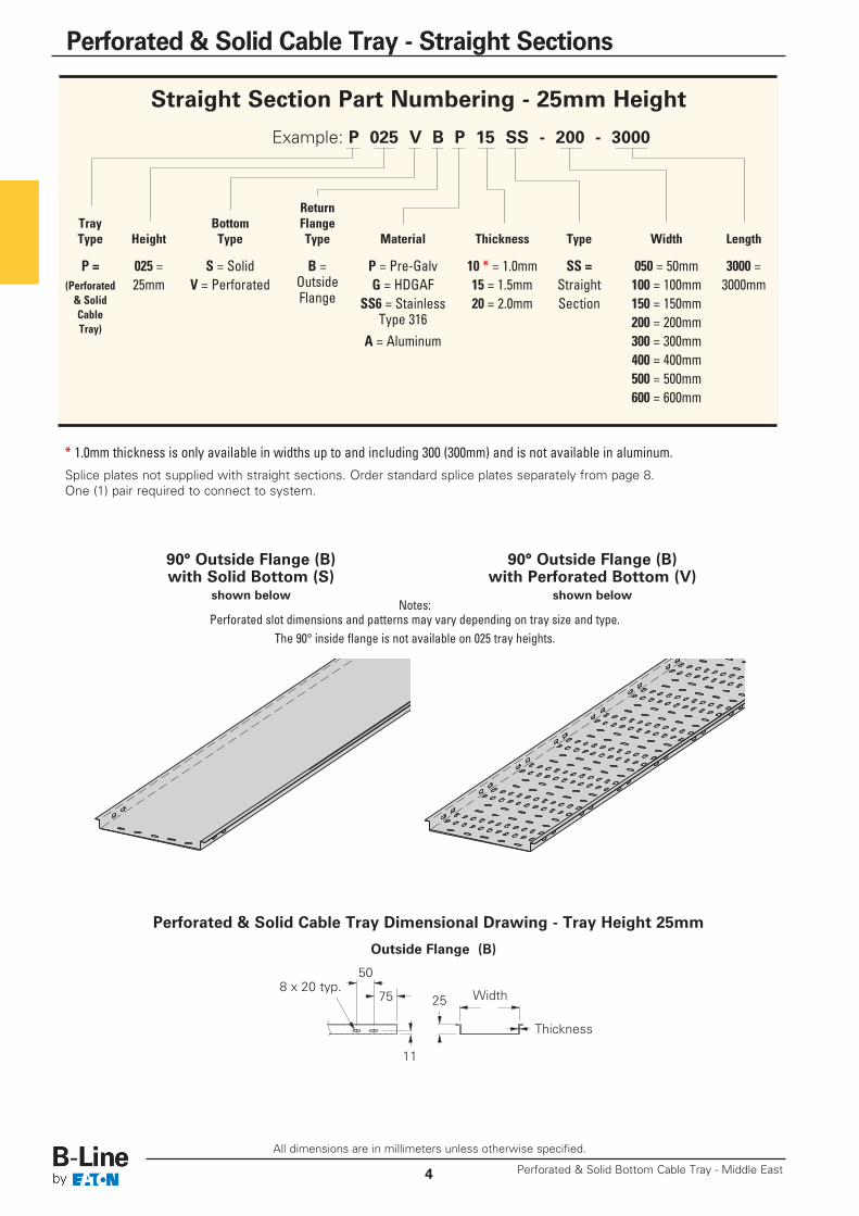
Perforated & Solid Cable Tray Dimensional Drawing - Tray Height 25mm
Outside Flange (B)
Width2575
50
Thickness
Straight Section Part Numbering - 25mm Height
Example: P 025 V B P 15 SS - 200 - 3000
ReturnTray Bottom FlangeType Height Type Type Material Thickness Type Width Length
P = 025 = S = Solid B = P = Pre-Galv 10 * = 1.0mm SS = 050 = 50mm 3000 = (Perforated 25mm V = Perforated Outside G = HDGAF 15 = 1.5mm Straight 100 = 100mm 3000mm& Solid Flange SS6 = Stainless 20 = 2.0mm Section 150 = 150mmCable Type 316 200 = 200mmTray)
A = Aluminum 300 = 300mm400 = 400mm500 = 500mm600 = 600mm
Notes:Perforated slot dimensions and patterns may vary depending on tray size and type.
The 90° inside flange is not available on 025 tray heights.
90° Outside Flange (B)with Solid Bottom (S)
shown below
90° Outside Flange (B)with Perforated Bottom (V)
shown below
* 1.0mm thickness is only available in widths up to and including 300 (300mm) and is not available in aluminum.Splice plates not supplied with straight sections. Order standard splice plates separately from page 8.One (1) pair required to connect to system.
Perforated & Solid Bottom Cable Tray - Middle East4
Perforated & Solid Cable Tray - Straight Sections
11
8 x 20 typ.
Outside Flange (B)
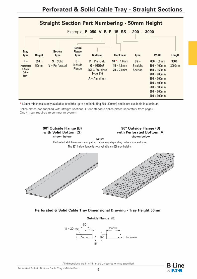
Perforated & Solid Cable Tray Dimensional Drawing - Tray Height 50mm
Width
50
15
75
508 x 20 typ.
Thickness
All dimensions are in millimeters unless otherwise specified.
5
Perforated & Solid Cable Tray - Straight Sections
Perforated & Solid Bottom Cable Tray - Middle East
Straight Section Part Numbering - 50mm Height
Example: P 050 V B P 15 SS - 200 - 3000
ReturnTray Bottom FlangeType Height Type Type Material Thickness Type Width Length
P = 050 = S = Solid B = P = Pre-Galv 10 * = 1.0mm SS = 050 = 50mm 3000 = (Perforated 50mm V = Perforated Outside G = HDGAF 15 = 1.5mm Straight 100 = 100mm 3000mm& Solid Flange SS6 = Stainless 20 = 2.0mm Section 150 = 150mmCable Type 316 200 = 200mmTray)
A = Aluminum 300 = 300mm400 = 400mm500 = 500mm600 = 600mm900 = 900mm
Notes:Perforated slot dimensions and patterns may vary depending on tray size and type.
The 90° inside flange is not available on 050 tray heights.
90° Outside Flange (B)with Solid Bottom (S)
shown below
90° Outside Flange (B)with Perforated Bottom (V)
shown below
* 1.0mm thickness is only available in widths up to and including 300 (300mm) and is not available in aluminum.Splice plates not supplied with straight sections. Order standard splice plates separately from page 8.One (1) pair required to connect to system.

All dimensions are in millimeters unless otherwise specified.
90° Outside Flange (B) 90° Inside Flange (C)
Perforated & Solid Cable Tray Dimensional Drawing - Tray Height 75mm
Width Width
75 75
15
2575 75
25
50 50
Thickness
8 x 20 typ.
Thickness
Note:Perforated slot dimensions and patterns may vary depending on tray size and type.
90° Outside Flange (B)with Solid Bottom (S)
shown below
90° Inside Flange (C)with Perforated Bottom (V)
shown below
* 1.0mm thickness is only available in widths up to and including 300 (300mm) and is not available in aluminum.Splice plates not supplied with straight sections. Order standard splice plates separately from page 8.One (1) pair required to connect to system.
Perforated & Solid Bottom Cable Tray - Middle East6
Perforated & Solid Cable Tray - Straight Sections
Straight Section Part Numbering - 75mm Height
Example: P 075 V C P 15 SS - 200 - 3000
ReturnTray Bottom FlangeType Height Type Type Material Thickness Type Width Length
P = 075 = S = Solid C = P = Pre-Galv 10 * = 1.0mm SS = 100 = 100mm 3000 = (Perforated 75mm V = Perforated Inside G = HDGAF 15 = 1.5mm Straight 150 = 150mm 3000mm& Solid Flange SS6 = Stainless 20 = 2.0mm Section 200 = 200mmCable B = Type 316 300 = 300mmTray)
Outside A = Aluminum 400 = 400mmFlange 500 = 500mm
600 = 600mm900 = 900mm
15
8 x 20 typ.
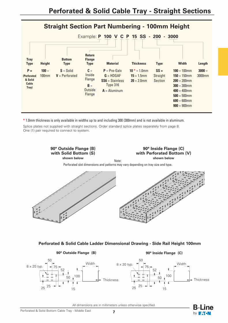
90° Outside Flange (B) 90° Inside Flange (C)
Perforated & Solid Cable Ladder Dimensional Drawing - Side Rail Height 100mm
Width Width
100 100
15
50
152525
50
5275 75
50 50
Thickness
8 x 20 typ. 8 x 20 typ.
Thickness
Note:Perforated slot dimensions and patterns may vary depending on tray size and type.
90° Outside Flange (B)with Solid Bottom (S)
shown below
90° Inside Flange (C)with Perforated Bottom (V)
shown below
* 1.0mm thickness is only available in widths up to and including 300 (300mm) and is not available in aluminum.Splice plates not supplied with straight sections. Order standard splice plates separately from page 8.One (1) pair required to connect to system.
All dimensions are in millimeters unless otherwise specified.
7
Perforated & Solid Cable Tray - Straight Sections
Perforated & Solid Bottom Cable Tray - Middle East
Straight Section Part Numbering - 100mm Height
Example: P 100 V C P 15 SS - 200 - 3000
ReturnTray Bottom FlangeType Height Type Type Material Thickness Type Width Length
P = 100 = S = Solid C = P = Pre-Galv 10 * = 1.0mm SS = 100 = 100mm 3000 = (Perforated 100mm V = Perforated Inside G = HDGAF 15 = 1.5mm Straight 150 = 150mm 3000mm& Solid Flange SS6 = Stainless 20 = 2.0mm Section 200 = 200mmCable B = Type 316 300 = 300mmTray)
Outside A = Aluminum 400 = 400mmFlange 500 = 500mm
600 = 600mm900 = 900mm
2525
52

All dimensions are in millimeters unless otherwise specified.
Perforated & Solid Bottom Cable Tray - Middle East8
Perforated & Solid Cable Tray - Accessories
Part Number Tray Widths Plate Width Number of Slots
PBS**-1 50 - 100 44 2PBS**-2 150 - 300 144 4PBS**-3 400 - 500 244 4PBS**-4 600 444 6PBS**-5 900 644 6
Bottom Splice Plates (Mounted on bottom of trays as splice plates or to stabilize connections on wider trays)(Sold Individually With Hardware)• ** Insert P for Pre-Galvanized,
G for Hot Dip Galvanized,SS6 for Stainless Steel 316A for Aluminum
Trays
PBS**-1
PBS**-2PBS**-3
PBS**-4PBS**-5
Splice PlateSplicePlate
Trays
SplicePlate
Trays
Vertical Adjustable Splice Plates (Outside mount)(Sold in Pairs With Hardware)• ** Insert P for Pre-Galvanized, G for Hot Dip Galvanized,
SS6 for Stainless Steel 316, A for Aluminum
Horizontal Adjustable Splice Plates (Outside mount)(Sold in Pairs With Hardware)• ** Insert P for Pre-Galvanized, G for Hot Dip Galvanized,
SS6 for Stainless Steel 316, A for Aluminum• Requires mitering of trays and drilling new splice plate holes on inside angle
Miter 1/2 therequired angleon each tray end
Example:40° bend requires20° miter each end angle
Part Number Tray Height
PSP025** 25PSP050** 50PSP075** 75PSP100** 100
Side Splice Plates (Outside mount)(Sold in Pairs With Hardware)• ** Insert P for Pre-Galvanized, G for Hot Dip Galvanized,
SS6 for Stainless Steel 316, A for Aluminum
PSP075 shown
PSP050 shown
PHA050 shownPHA075 shown
PVA050 shown
PVA075 shown
Part Number Tray Height
PHAM025** 25PHAM050** 50PHAM075** 75PHAM100** 100
Part Number Tray Height
PVA025** 25PVA050** 50PVA075** 75PVA100** 100

All dimensions are in millimeters unless otherwise specified.
9
Perforated & Solid Cable Tray - Accessories
Perforated & Solid Bottom Cable Tray - Middle East
Right Reducer Splice Plates (Mounted outside of tray)(Sold as a Set With Hardware)• ** Insert P for Pre-Galvanized, G for Hot Dip Galvanized,
SS6 for Stainless Steel 316, A for Aluminum• __ Width: Insert width difference between the two trays
Straight Reducer Splice Plates (Mounted outside of tray)(Sold as a Set With Hardware)• ** Insert P for Pre-Galvanized, G for Hot Dip Galvanized,
SS6 for Stainless Steel 316, A for Aluminum• __ Width: Insert width difference between the two trays
Left Reducer Splice Plates (Mounted outside of tray)(Sold as a Set With Hardware)• ** Insert P for Pre-Galvanized, G for Hot Dip Galvanized,
SS6 for Stainless Steel 316, A for Aluminum• __ Width: Insert width difference between the two trays
Blind End (Mounted outside of tray)(Sold Individually With Hardware)• ** Insert P for Pre-Galvanized, G for Hot Dip Galvanized,
SS6 for Stainless Steel 316, A for Aluminum• __ Tray Width
Part Number Tray Height
PBE025**-__ 25PBE050**-__ 50PBE075**-__ 75PBE100**-__ 100
Part Number Tray Height
PLR025**-__ 25PLR050**-__ 50PLR075**-__ 75PLR100**-__ 100
Part Number Tray Height
PRR025**-__ 25PRR050**-__ 50PRR075**-__ 75PRR100**-__ 100
Part Number Tray Height
PSR025**-__ 25PSR050**-__ 50PSR075**-__ 75PSR100**-__ 100

All dimensions are in millimeters unless otherwise specified.
Perforated & Solid Bottom Cable Tray - Middle East10
Perforated & Solid Cable Tray - Accessories
Drop-Out(Sold Individually With Hardware)• ** Insert P for Pre-Galvanized, G for Hot Dip Galvanized,
SS6 for Stainless Steel 316, A for Aluminum
Part Number Tray Width
PDO**-050 50PDO**-100 100PDO**-150 150PDO**-200 200PDO**-300 300PDO**-400 400PDO**-500 500PDO**-600 600PDO**-900 900
Wrap-Around Cover Clamps(Sold Individually With Hardware)• ** Insert P for Pre-Galvanized, G for Hot Dip Galvanized,
SS6 for Stainless Steel 316, A for Aluminum• __ Insert Tray Width of 050 = 50mm, 100 = 100mm, 150 = 150mm, 200 = 200mm,
300 = 300mm, 400 = 400mm, 500 = 500mm, 600 = 600mm, 900 = 900mm
* Is not available in 900mm wide tray
Part Number Item
M6 x 16 PHS (*) Phillips Head ScrewM6 SFHN (*) Serrated Flange Hex Nut
Accessory Hardware• (*) Insert HDG for Hot Dip Galvanized SS6 for Stainless Steel 316
Hold Downs - For (B) & (C) Flanges(Sold in Pairs With Hardware)• ** Insert P for Pre-Galvanized, G for Hot Dip Galvanized,
SS6 for Stainless Steel 316, A for Aluminum
Part Number Tray Height
PHD025** 25PHD050** 50PHD075** 75PHD100** 100
Part Number Tray Height
PWCC025**-__ 25 *PWCC050**-__ 50PWCC075**-__ 75PWCC100**-__ 100
C-Shape Cover Clamps - For (B) & (C) Flanges(Sold in Pairs With Hardware)• ** Insert P for Pre-Galvanized, G for Hot Dip Galvanized,
SS6 for Stainless Steel 316, A for Aluminum
Part Number Tray Height
PCCC025** 25PCCC050** 50PCCC075** 75PCCC100** 100
All dimensions are in millimeters unless otherwise specified.
11
Perforated & Solid Cable Tray - Fittings
Perforated & Solid Bottom Cable Tray - Middle East
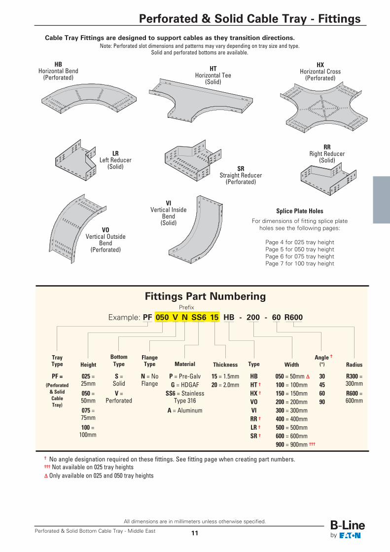
Cable Tray Fittings are designed to support cables as they transition directions.Note: Perforated slot dimensions and patterns may vary depending on tray size and type.
Solid and perforated bottoms are available.
Fittings Part Numbering
Example: PF 050 V N SS6 15 HB - 200 - 60 R600
Tray Bottom Flange Angle †Type Height Type Type Material Thickness Type Width (°) Radius
PF = 025 = S = N = No P = Pre-Galv 15 = 1.5mm HB 050 = 50mm D 30 R300 =(Perforated 25mm Solid Flange G = HDGAF 20 = 2.0mm HT † 100 = 100mm 45 300mm& Solid 050 = V = SS6 = Stainless HX † 150 = 150mm 60 R600 =Cable 50mm Perforated Type 316 VO 200 = 200mm 90 600mmTray)
075 = A = Aluminum VI 300 = 300mm75mm RR † 400 = 400mm100 = LR † 500 = 500mm100mm SR † 600 = 600mm
900 = 900mm †††
Prefix
HBHorizontal Bend(Perforated)
HTHorizontal Tee(Solid)
HXHorizontal Cross(Perforated)
VOVertical Outside
Bend(Perforated)
VIVertical Inside
Bend(Solid)
LRLeft Reducer(Solid)
RRRight Reducer(Solid)
SRStraight Reducer(Perforated)
† No angle designation required on these fittings. See fitting page when creating part numbers.††† Not available on 025 tray heightsD Only available on 025 and 050 tray heights
Splice Plate HolesFor dimensions of fitting splice plate
holes see the following pages:
Page 4 for 025 tray heightPage 5 for 050 tray heightPage 6 for 075 tray heightPage 7 for 100 tray height

All dimensions are in millimeters unless otherwise specified.
Perforated & Solid Bottom Cable Tray - Middle East12
Perforated & Solid Cable Tray - Fittings
Horizontal Bends 90° (HB)Splice plates not supplied with fittings.Order standard splice plates separately from page 8.One (1) pair required to connect to system.
90˚ Horizontal BendSolid
Need Hole Pattern
A
140
140
W
R
B
(Prefix) See page 11 for catalog number prefix and splice plate hole information.Width dimensions are to inside wall. Manufacturing tolerances apply to all dimensions.
Note:Perforated slot dimensions and patternsmay vary depending on tray size and type.
90˚ Horizontal BendPerforated
Bend Tray 90˚ Horizontal Bend DimensionsRadius Width Formed Radius FittingsR W Catalog No. A Bmm mm mm mm
50 PF(Prefix)HB-050-90R300 490 490100 PF(Prefix)HB-100-90R300 540 540150 PF(Prefix)HB-150-90R300 590 590200 PF(Prefix)HB-200-90R300 640 640
300 300 PF(Prefix)HB-300-90R300 740 740400 PF(Prefix)HB-400-90R300 840 840500 PF(Prefix)HB-500-90R300 940 940600 PF(Prefix)HB-600-90R300 1040 1040900 PF(Prefix)HB-900-90R300 1340 134050 PF(Prefix)HB-050-90R600 790 790100 PF(Prefix)HB-100-90R600 840 840150 PF(Prefix)HB-150-90R600 890 890200 PF(Prefix)HB-200-90R600 940 940
600 300 PF(Prefix)HB-300-90R600 1040 1040400 PF(Prefix)HB-400-90R600 1140 1140500 PF(Prefix)HB-500-90R600 1240 1240600 PF(Prefix)HB-600-90R600 1340 1340900 PF(Prefix)HB-900-90R600 1640 1640

All dimensions are in millimeters unless otherwise specified.
13
Perforated & Solid Cable Tray - Fittings
Perforated & Solid Bottom Cable Tray - Middle East
Horizontal Bends 60° (HB)Splice plates not supplied with fittings.
Order standard splice plates separately from page 8.One (1) pair required to connect to system.Need Hole Pattern
140
140
B
60˚ Horizontal BendSolid
R
A
(Prefix) See page 11 for catalog number prefix and splice plate hole information.Width dimensions are to inside wall. Manufacturing tolerances apply to all dimensions.
Note:Perforated slot dimensions and patternsmay vary depending on tray size and type.
W
60˚ Horizontal BendPerforated
Bend Tray 60˚ Horizontal Bend DimensionsRadius Width Formed Radius FittingsR W Catalog No. A Bmm mm mm mm
50 PF(Prefix)HB-050-60R300 321 513100 PF(Prefix)HB-100-60R300 371 556150 PF(Prefix)HB-150-60R300 421 600200 PF(Prefix)HB-200-60R300 471 643
300 300 PF(Prefix)HB-300-60R300 571 730400 PF(Prefix)HB-400-60R300 671 816500 PF(Prefix)HB-500-60R300 771 903600 PF(Prefix)HB-600-60R300 871 989900 PF(Prefix)HB-900-60R300 1171 124950 PF(Prefix)HB-050-60R600 471 773100 PF(Prefix)HB-100-60R600 521 816150 PF(Prefix)HB-150-60R600 571 850200 PF(Prefix)HB-200-60R600 621 903
600 300 PF(Prefix)HB-300-60R600 721 989400 PF(Prefix)HB-400-60R600 821 1076500 PF(Prefix)HB-500-60R600 921 1163600 PF(Prefix)HB-600-60R600 1021 1249900 PF(Prefix)HB-900-60R600 1321 1509

All dimensions are in millimeters unless otherwise specified.
Perforated & Solid Bottom Cable Tray - Middle East14
Perforated & Solid Cable Tray - Fittings
Horizontal Bends 45° (HB)Splice plates not supplied with fittings.Order standard splice plates separately from page 8.One (1) pair required to connect to system.
45˚ Horizontal BendSolid
Need Hole Pattern
140
140
BR
AW
(Prefix) See page 11 for catalog number prefix and splice plate hole information.Width dimensions are to inside wall. Manufacturing tolerances apply to all dimensions.
Note:Perforated slot dimensions and patternsmay vary depending on tray size and type.
45˚ Horizontal BendPerforated
Bend Tray 45˚ Horizontal Bend DimensionsRadius Width Formed Radius FittingsR W Catalog No. A Bmm mm mm mm
50 PF(Prefix)HB-050-45R300 237 486100 PF(Prefix)HB-100-45R300 287 522150 PF(Prefix)HB-150-45R300 337 557200 PF(Prefix)HB-200-45R300 387 593
300 300 PF(Prefix)HB-300-45R300 487 663400 PF(Prefix)HB-400-45R300 587 734500 PF(Prefix)HB-500-45R300 687 805600 PF(Prefix)HB-600-45R300 787 875900 PF(Prefix)HB-900-45R300 1087 108850 PF(Prefix)HB-050-45R600 325 699100 PF(Prefix)HB-100-45R600 375 734150 PF(Prefix)HB-150-45R600 425 769200 PF(Prefix)HB-200-45R600 475 805
600 300 PF(Prefix)HB-300-45R600 575 875400 PF(Prefix)HB-400-45R600 675 946500 PF(Prefix)HB-500-45R600 775 1017600 PF(Prefix)HB-600-45R600 875 1088900 PF(Prefix)HB-900-45R600 1175 1300

All dimensions are in millimeters unless otherwise specified.
15
Perforated & Solid Cable Tray - Fittings
Perforated & Solid Bottom Cable Tray - Middle East
Horizontal Bends 30° (HB)Splice plates not supplied with fittings.
Order standard splice plates separately from page 8.One (1) pair required to connect to system.
Need Hole Pattern
30˚ Horizontal BendSolid
(Prefix) See page 11 for catalog number prefix and splice plate hole information.Width dimensions are to inside wall. Manufacturing tolerances apply to all dimensions.
Note:Perforated slot dimensions and patternsmay vary depending on tray size and type.
140
140
BR
AW
30˚ Horizontal BendPerforated
Bend Tray 30˚ Horizontal Bend DimensionsRadius Width Formed Radius FittingsR W Catalog No. A Bmm mm mm mm
50 PF(Prefix)HB-050-30R300 160 436100 PF(Prefix)HB-100-30R300 210 461150 PF(Prefix)HB-150-30R300 260 486200 PF(Prefix)HB-200-30R300 310 511
300 300 PF(Prefix)HB-300-30R300 410 561400 PF(Prefix)HB-400-30R300 510 611500 PF(Prefix)HB-500-30R300 610 661600 PF(Prefix)HB-600-30R300 710 711900 PF(Prefix)HB-900-30R300 1010 86150 PF(Prefix)HB-050-30R600 200 586100 PF(Prefix)HB-100-30R600 250 611150 PF(Prefix)HB-150-30R600 300 636200 PF(Prefix)HB-200-30R600 350 661
600 300 PF(Prefix)HB-300-30R600 450 711400 PF(Prefix)HB-400-30R600 550 761500 PF(Prefix)HB-500-30R600 650 811600 PF(Prefix)HB-600-30R600 750 861900 PF(Prefix)HB-900-30R600 1050 1011

All dimensions are in millimeters unless otherwise specified.
Perforated & Solid Bottom Cable Tray - Middle East16
Perforated & Solid Cable Tray - Fittings
Horizontal Tee (HT)Splice plates not supplied with fittings.Order standard splice plates separately from page 8.Two (2) pair required to connect to system.
A
B
R
W
Horizontal TeeSolid
(Prefix) See page 11 for catalog number prefix and splice plate hole information.Width dimensions are to inside wall. Manufacturing tolerances apply to all dimensions.
140140140
Note:Perforated slot dimensions and patternsmay vary depending on tray size and type.
Horizontal TeePerforated
Bend Tray Horizontal Cross DimensionsRadius Width Formed Radius FittingsR W Catalog No. A Bmm mm mm mm
50 PF(Prefix)HT-050-R300 490 930100 PF(Prefix)HT-100-R300 540 980150 PF(Prefix)HT-150-R300 590 1030200 PF(Prefix)HT-200-R300 640 1080
300 300 PF(Prefix)HT-300-R300 740 1180400 PF(Prefix)HT-400-R300 840 1280500 PF(Prefix)HT-500-R300 940 1380600 PF(Prefix)HT-600-R300 1040 1480900 PF(Prefix)HT-900-R300 1340 178050 PF(Prefix)HT-050-R600 790 1530100 PF(Prefix)HT-100-R600 840 1580150 PF(Prefix)HT-150-R600 890 1630200 PF(Prefix)HT-200-R600 940 1680
600 300 PF(Prefix)HT-300-R600 1040 1780400 PF(Prefix)HT-400-R600 1140 1880500 PF(Prefix)HT-500-R600 1240 1980600 PF(Prefix)HT-600-R600 1340 2080900 PF(Prefix)HT-900-R600 1640 2380
All dimensions are in millimeters unless otherwise specified.
17
Perforated & Solid Cable Tray - Fittings
Perforated & Solid Bottom Cable Tray - Middle East
A
R
B
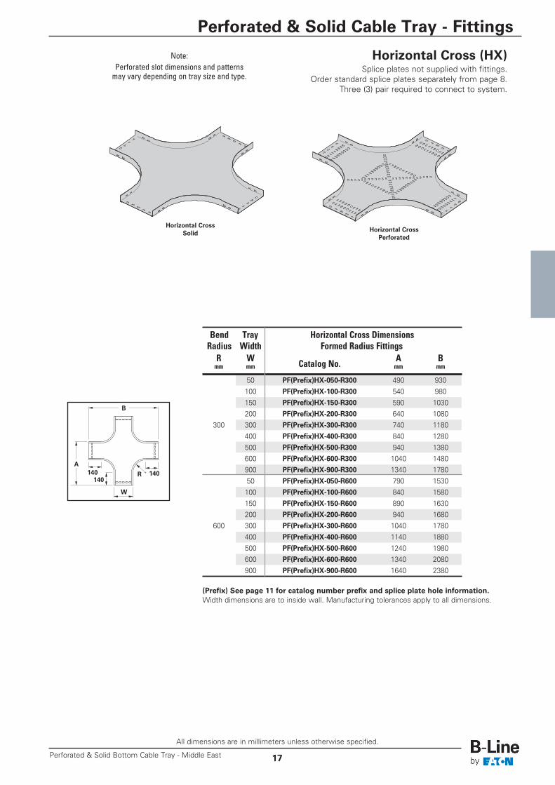
Horizontal Cross (HX)Splice plates not supplied with fittings.
Order standard splice plates separately from page 8.Three (3) pair required to connect to system.
W
(Prefix) See page 11 for catalog number prefix and splice plate hole information.Width dimensions are to inside wall. Manufacturing tolerances apply to all dimensions.
Horizontal CrossSolid
Bend Tray Horizontal Cross DimensionsRadius Width Formed Radius FittingsR W Catalog No. A Bmm mm mm mm
50 PF(Prefix)HX-050-R300 490 930100 PF(Prefix)HX-100-R300 540 980150 PF(Prefix)HX-150-R300 590 1030200 PF(Prefix)HX-200-R300 640 1080
300 300 PF(Prefix)HX-300-R300 740 1180400 PF(Prefix)HX-400-R300 840 1280500 PF(Prefix)HX-500-R300 940 1380600 PF(Prefix)HX-600-R300 1040 1480900 PF(Prefix)HX-900-R300 1340 178050 PF(Prefix)HX-050-R600 790 1530100 PF(Prefix)HX-100-R600 840 1580150 PF(Prefix)HX-150-R600 890 1630200 PF(Prefix)HX-200-R600 940 1680
600 300 PF(Prefix)HX-300-R600 1040 1780400 PF(Prefix)HX-400-R600 1140 1880500 PF(Prefix)HX-500-R600 1240 1980600 PF(Prefix)HX-600-R600 1340 2080900 PF(Prefix)HX-900-R600 1640 2380
140140140
Note:Perforated slot dimensions and patternsmay vary depending on tray size and type.
Horizontal CrossPerforated
All dimensions are in millimeters unless otherwise specified.
Perforated & Solid Bottom Cable Tray - Middle East18
Perforated & Solid Cable Tray - Fittings
Right Left
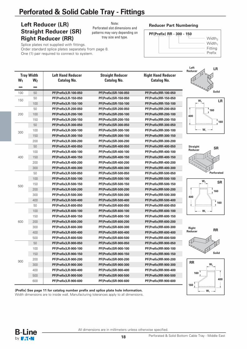
Left Reducer (LR)Straight Reducer (SR)Right Reducer (RR)Splice plates not supplied with fittings.Order standard splice plates separately from page 8.One (1) pair required to connect to system.
PF(Prefix) RR - 300 - 150Width2Width1FittingPrefix
160
160
W2
W1
LR
LR
400
W2 SR
SR
Reducer Part Numbering
Tray Width Left Hand Reducer Straight Reducer Right Hand ReducerW1 W2 Catalog No. Catalog No. Catalog No.mm mm
100 50 PF(Prefix)LR-100-050 PF(Prefix)SR-100-050 PF(Prefix)RR-100-050
15050 PF(Prefix)LR-150-050 PF(Prefix)SR-150-050 PF(Prefix)RR-150-050
100 PF(Prefix)LR-150-100 PF(Prefix)SR-150-100 PF(Prefix)RR-150-100
50 PF(Prefix)LR-200-050 PF(Prefix)SR-200-050 PF(Prefix)RR-200-050
200 100 PF(Prefix)LR-200-100 PF(Prefix)SR-200-100 PF(Prefix)RR-200-100
150 PF(Prefix)LR-200-150 PF(Prefix)SR-200-150 PF(Prefix)RR-200-150
50 PF(Prefix)LR-300-050 PF(Prefix)SR-300-050 PF(Prefix)RR-300-050
300100 PF(Prefix)LR-300-100 PF(Prefix)SR-300-100 PF(Prefix)RR-300-100
150 PF(Prefix)LR-300-150 PF(Prefix)SR-300-150 PF(Prefix)RR-300-150
200 PF(Prefix)LR-300-200 PF(Prefix)SR-300-200 PF(Prefix)RR-300-200
50 PF(Prefix)LR-400-050 PF(Prefix)SR-400-050 PF(Prefix)RR-400-050
100 PF(Prefix)LR-400-100 PF(Prefix)SR-400-100 PF(Prefix)RR-400-100
400 150 PF(Prefix)LR-400-150 PF(Prefix)SR-400-150 PF(Prefix)RR-400-150
200 PF(Prefix)LR-400-200 PF(Prefix)SR-400-200 PF(Prefix)RR-400-200
300 PF(Prefix)LR-400-300 PF(Prefix)SR-400-300 PF(Prefix)RR-400-300
50 PF(Prefix)LR-500-050 PF(Prefix)SR-500-050 PF(Prefix)RR-500-050
100 PF(Prefix)LR-500-100 PF(Prefix)SR-500-100 PF(Prefix)RR-500-100
500150 PF(Prefix)LR-500-150 PF(Prefix)SR-500-150 PF(Prefix)RR-500-150
200 PF(Prefix)LR-500-200 PF(Prefix)SR-500-200 PF(Prefix)RR-500-200
300 PF(Prefix)LR-500-300 PF(Prefix)SR-500-300 PF(Prefix)RR-500-300
400 PF(Prefix)LR-500-400 PF(Prefix)SR-500-400 PF(Prefix)RR-500-400
50 PF(Prefix)LR-600-050 PF(Prefix)SR-600-050 PF(Prefix)RR-600-050
100 PF(Prefix)LR-600-100 PF(Prefix)SR-600-100 PF(Prefix)RR-600-100
150 PF(Prefix)LR-600-150 PF(Prefix)SR-600-150 PF(Prefix)RR-600-150
600 200 PF(Prefix)LR-600-200 PF(Prefix)SR-600-200 PF(Prefix)RR-600-200
300 PF(Prefix)LR-600-300 PF(Prefix)SR-600-300 PF(Prefix)RR-600-300
400 PF(Prefix)LR-600-400 PF(Prefix)SR-600-400 PF(Prefix)RR-600-400
500 PF(Prefix)LR-600-500 PF(Prefix)SR-600-500 PF(Prefix)RR-600-500
50 PF(Prefix)LR-900-050 PF(Prefix)SR-900-050 PF(Prefix)RR-900-050
100 PF(Prefix)LR-900-100 PF(Prefix)SR-900-100 PF(Prefix)RR-900-100
150 PF(Prefix)LR-900-150 PF(Prefix)SR-900-150 PF(Prefix)RR-900-150
900200 PF(Prefix)LR-900-200 PF(Prefix)SR-900-200 PF(Prefix)RR-900-200
300 PF(Prefix)LR-900-300 PF(Prefix)SR-900-300 PF(Prefix)RR-900-300
400 PF(Prefix)LR-900-400 PF(Prefix)SR-900-400 PF(Prefix)RR-900-400
500 PF(Prefix)LR-900-500 PF(Prefix)SR-900-500 PF(Prefix)RR-900-500
600 PF(Prefix)LR-900-600 PF(Prefix)SR-900-600 PF(Prefix)RR-900-600
(Prefix) See page 11 for catalog number prefix and splice plate hole information.Width dimensions are to inside wall. Manufacturing tolerances apply to all dimensions.
LeftReducer
Solid
Perforated
StraightReducer
W1
160
160
Right Left
RRRight
Reducer
Solid
Note:Perforated slot dimensions andpatterns may vary depending on
tray size and type.
160
160
400
400
W2RR
W1
All dimensions are in millimeters unless otherwise specified.
19
Perforated & Solid Cable Tray - Fittings
Perforated & Solid Bottom Cable Tray - Middle East
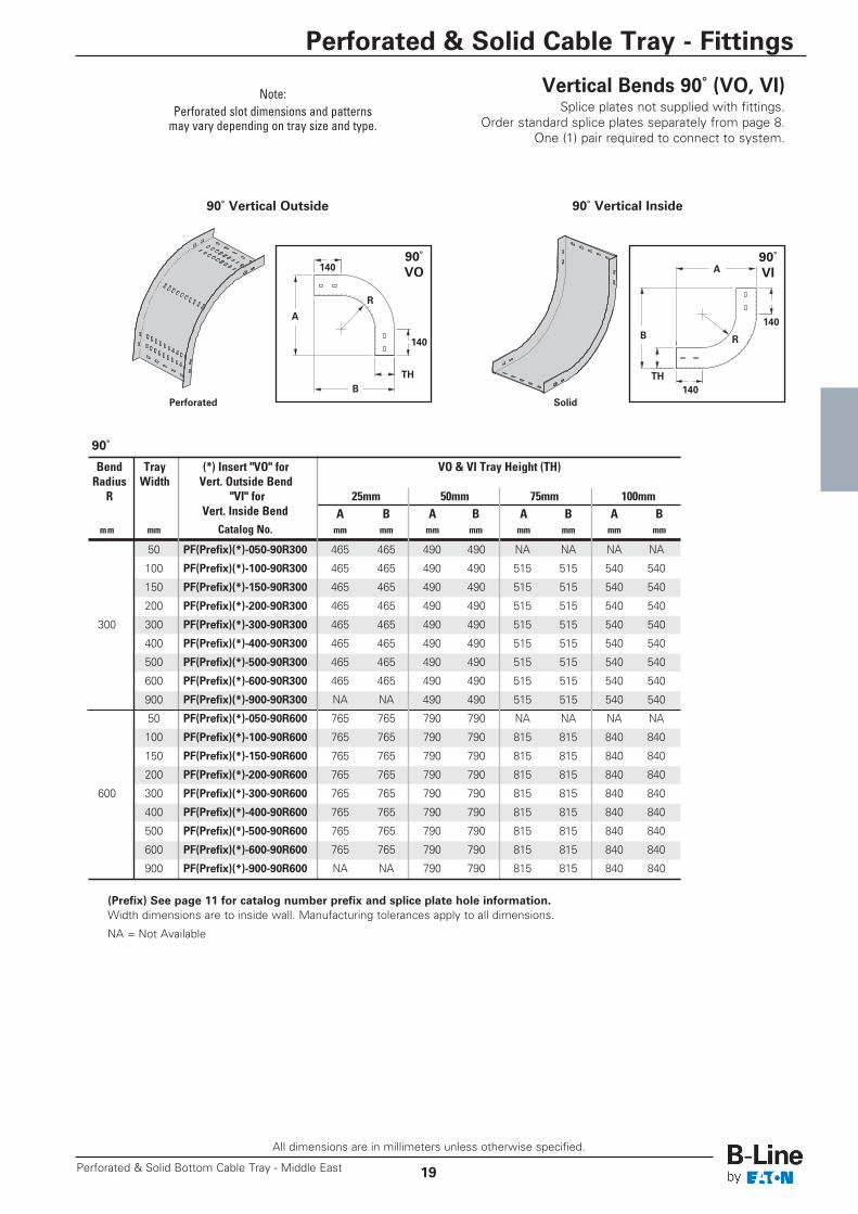
Vertical Bends 90˚ (VO, VI) Splice plates not supplied with fittings.
Order standard splice plates separately from page 8.One (1) pair required to connect to system.
90˚ Vertical Outside 90˚ Vertical Inside
90˚VI
90˚VO
(Prefix) See page 11 for catalog number prefix and splice plate hole information.Width dimensions are to inside wall. Manufacturing tolerances apply to all dimensions.
NA = Not Available
90˚
Bend Tray (*) Insert "VO" for VO & VI Tray Height (TH)Radius Width Vert. Outside BendR "VI" for 25mm 50mm 75mm 100mm
Vert. Inside Bend A B A B A B A Bmm mm Catalog No. mm mm mm mm mm mm mm mm
50 PF(Prefix)(*)-050-90R300 465 465 490 490 NA NA NA NA
100 PF(Prefix)(*)-100-90R300 465 465 490 490 515 515 540 540
150 PF(Prefix)(*)-150-90R300 465 465 490 490 515 515 540 540
200 PF(Prefix)(*)-200-90R300 465 465 490 490 515 515 540 540
300 300 PF(Prefix)(*)-300-90R300 465 465 490 490 515 515 540 540
400 PF(Prefix)(*)-400-90R300 465 465 490 490 515 515 540 540
500 PF(Prefix)(*)-500-90R300 465 465 490 490 515 515 540 540
600 PF(Prefix)(*)-600-90R300 465 465 490 490 515 515 540 540
900 PF(Prefix)(*)-900-90R300 NA NA 490 490 515 515 540 540
50 PF(Prefix)(*)-050-90R600 765 765 790 790 NA NA NA NA
100 PF(Prefix)(*)-100-90R600 765 765 790 790 815 815 840 840
150 PF(Prefix)(*)-150-90R600 765 765 790 790 815 815 840 840
200 PF(Prefix)(*)-200-90R600 765 765 790 790 815 815 840 840
600 300 PF(Prefix)(*)-300-90R600 765 765 790 790 815 815 840 840
400 PF(Prefix)(*)-400-90R600 765 765 790 790 815 815 840 840
500 PF(Prefix)(*)-500-90R600 765 765 790 790 815 815 840 840
600 PF(Prefix)(*)-600-90R600 765 765 790 790 815 815 840 840
900 PF(Prefix)(*)-900-90R600 NA NA 790 790 815 815 840 840
140
140
BTH
A
R
140
140B
A
R
Note:Perforated slot dimensions and patternsmay vary depending on tray size and type.
Perforated Solid
TH
All dimensions are in millimeters unless otherwise specified.
Perforated & Solid Bottom Cable Tray - Middle East20
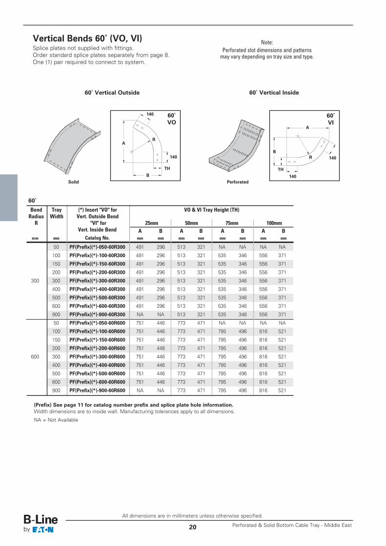
Vertical Bends 60˚ (VO, VI)Splice plates not supplied with fittings.Order standard splice plates separately from page 8.One (1) pair required to connect to system.
60˚VI
60˚VO
(Prefix) See page 11 for catalog number prefix and splice plate hole information.Width dimensions are to inside wall. Manufacturing tolerances apply to all dimensions.
NA = Not Available
60˚
60˚ Vertical Outside 60˚ Vertical Inside
140
140
A
B
R
140
140B
A
R
Note:Perforated slot dimensions and patternsmay vary depending on tray size and type.
Solid Perforated
TH TH
Bend Tray (*) Insert "VO" for VO & VI Tray Height (TH)Radius Width Vert. Outside BendR "VI" for 25mm 50mm 75mm 100mm
Vert. Inside Bend A B A B A B A Bmm mm Catalog No. mm mm mm mm mm mm mm mm
50 PF(Prefix)(*)-050-60R300 491 296 513 321 NA NA NA NA
100 PF(Prefix)(*)-100-60R300 491 296 513 321 535 346 556 371
150 PF(Prefix)(*)-150-60R300 491 296 513 321 535 346 556 371
200 PF(Prefix)(*)-200-60R300 491 296 513 321 535 346 556 371
300 300 PF(Prefix)(*)-300-60R300 491 296 513 321 535 346 556 371
400 PF(Prefix)(*)-400-60R300 491 296 513 321 535 346 556 371
500 PF(Prefix)(*)-500-60R300 491 296 513 321 535 346 556 371
600 PF(Prefix)(*)-600-60R300 491 296 513 321 535 346 556 371
900 PF(Prefix)(*)-900-60R300 NA NA 513 321 535 346 556 371
50 PF(Prefix)(*)-050-60R600 751 446 773 471 NA NA NA NA
100 PF(Prefix)(*)-100-60R600 751 446 773 471 795 496 816 521
150 PF(Prefix)(*)-150-60R600 751 446 773 471 795 496 816 521
200 PF(Prefix)(*)-200-60R600 751 446 773 471 795 496 816 521
600 300 PF(Prefix)(*)-300-60R600 751 446 773 471 795 496 816 521
400 PF(Prefix)(*)-400-60R600 751 446 773 471 795 496 816 521
500 PF(Prefix)(*)-500-60R600 751 446 773 471 795 496 816 521
600 PF(Prefix)(*)-600-60R600 751 446 773 471 795 496 816 521
900 PF(Prefix)(*)-900-60R600 NA NA 773 471 795 496 816 521
All dimensions are in millimeters unless otherwise specified.
21
Perforated & Solid Cable Tray - Fittings
Perforated & Solid Bottom Cable Tray - Middle East
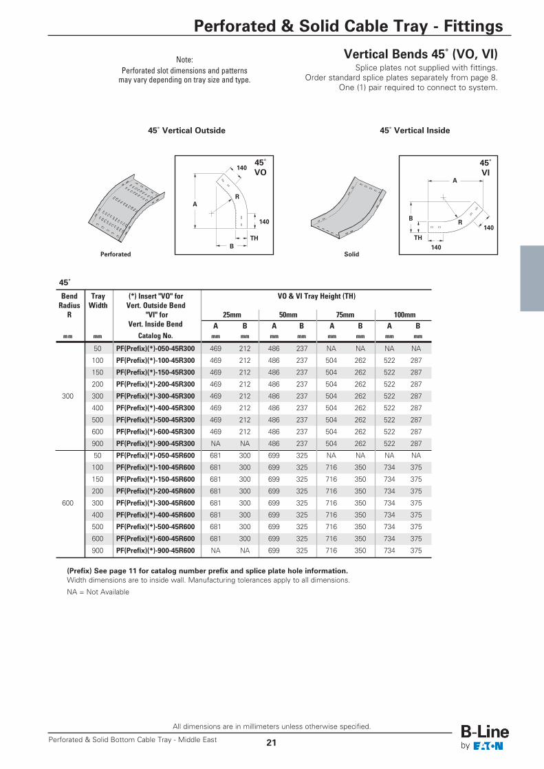
Vertical Bends 45˚ (VO, VI) Splice plates not supplied with fittings.
Order standard splice plates separately from page 8.One (1) pair required to connect to system.
45˚VI
45˚VO
(Prefix) See page 11 for catalog number prefix and splice plate hole information.Width dimensions are to inside wall. Manufacturing tolerances apply to all dimensions.
NA = Not Available
45˚
45˚ Vertical Outside 45˚ Vertical Inside
140
140
A
B
B
A
R
140
140R
Note:Perforated slot dimensions and patternsmay vary depending on tray size and type.
Perforated Solid
TH TH
Bend Tray (*) Insert "VO" for VO & VI Tray Height (TH)Radius Width Vert. Outside BendR "VI" for 25mm 50mm 75mm 100mm
Vert. Inside Bend A B A B A B A Bmm mm Catalog No. mm mm mm mm mm mm mm mm
50 PF(Prefix)(*)-050-45R300 469 212 486 237 NA NA NA NA
100 PF(Prefix)(*)-100-45R300 469 212 486 237 504 262 522 287
150 PF(Prefix)(*)-150-45R300 469 212 486 237 504 262 522 287
200 PF(Prefix)(*)-200-45R300 469 212 486 237 504 262 522 287
300 300 PF(Prefix)(*)-300-45R300 469 212 486 237 504 262 522 287
400 PF(Prefix)(*)-400-45R300 469 212 486 237 504 262 522 287
500 PF(Prefix)(*)-500-45R300 469 212 486 237 504 262 522 287
600 PF(Prefix)(*)-600-45R300 469 212 486 237 504 262 522 287
900 PF(Prefix)(*)-900-45R300 NA NA 486 237 504 262 522 287
50 PF(Prefix)(*)-050-45R600 681 300 699 325 NA NA NA NA
100 PF(Prefix)(*)-100-45R600 681 300 699 325 716 350 734 375
150 PF(Prefix)(*)-150-45R600 681 300 699 325 716 350 734 375
200 PF(Prefix)(*)-200-45R600 681 300 699 325 716 350 734 375
600 300 PF(Prefix)(*)-300-45R600 681 300 699 325 716 350 734 375
400 PF(Prefix)(*)-400-45R600 681 300 699 325 716 350 734 375
500 PF(Prefix)(*)-500-45R600 681 300 699 325 716 350 734 375
600 PF(Prefix)(*)-600-45R600 681 300 699 325 716 350 734 375
900 PF(Prefix)(*)-900-45R600 NA NA 699 325 716 350 734 375
All dimensions are in millimeters unless otherwise specified.
Perforated & Solid Bottom Cable Tray - Middle East22
Perforated & Solid Cable Tray - Fittings
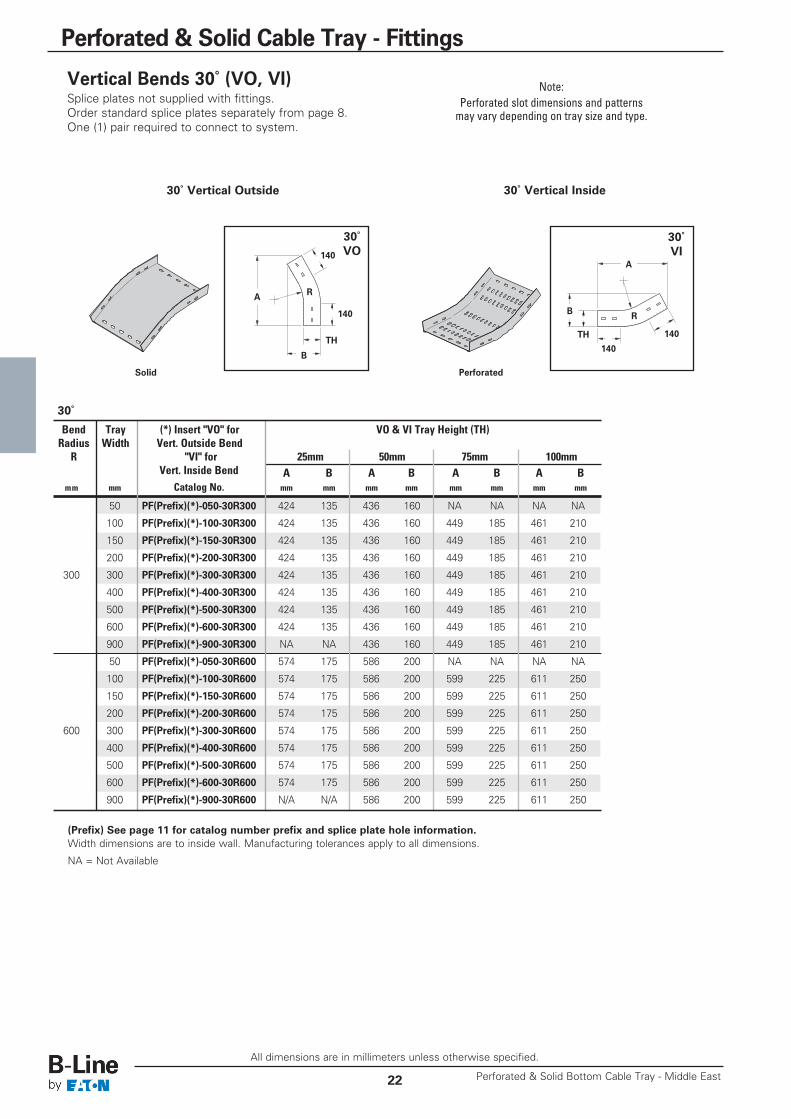
Vertical Bends 30˚ (VO, VI)Splice plates not supplied with fittings.Order standard splice plates separately from page 8.One (1) pair required to connect to system.
30˚VI
30˚VO
(Prefix) See page 11 for catalog number prefix and splice plate hole information.Width dimensions are to inside wall. Manufacturing tolerances apply to all dimensions.
NA = Not Available
30˚
Note:Perforated slot dimensions and patternsmay vary depending on tray size and type.
30˚ Vertical Outside 30˚ Vertical Inside
Solid Perforated
140
140
A
B
B
A
R
140
140
R
THTH
Bend Tray (*) Insert "VO" for VO & VI Tray Height (TH)Radius Width Vert. Outside BendR "VI" for 25mm 50mm 75mm 100mm
Vert. Inside Bend A B A B A B A Bmm mm Catalog No. mm mm mm mm mm mm mm mm
50 PF(Prefix)(*)-050-30R300 424 135 436 160 NA NA NA NA
100 PF(Prefix)(*)-100-30R300 424 135 436 160 449 185 461 210
150 PF(Prefix)(*)-150-30R300 424 135 436 160 449 185 461 210
200 PF(Prefix)(*)-200-30R300 424 135 436 160 449 185 461 210
300 300 PF(Prefix)(*)-300-30R300 424 135 436 160 449 185 461 210
400 PF(Prefix)(*)-400-30R300 424 135 436 160 449 185 461 210
500 PF(Prefix)(*)-500-30R300 424 135 436 160 449 185 461 210
600 PF(Prefix)(*)-600-30R300 424 135 436 160 449 185 461 210
900 PF(Prefix)(*)-900-30R300 NA NA 436 160 449 185 461 210
50 PF(Prefix)(*)-050-30R600 574 175 586 200 NA NA NA NA
100 PF(Prefix)(*)-100-30R600 574 175 586 200 599 225 611 250
150 PF(Prefix)(*)-150-30R600 574 175 586 200 599 225 611 250
200 PF(Prefix)(*)-200-30R600 574 175 586 200 599 225 611 250
600 300 PF(Prefix)(*)-300-30R600 574 175 586 200 599 225 611 250
400 PF(Prefix)(*)-400-30R600 574 175 586 200 599 225 611 250
500 PF(Prefix)(*)-500-30R600 574 175 586 200 599 225 611 250
600 PF(Prefix)(*)-600-30R600 574 175 586 200 599 225 611 250
900 PF(Prefix)(*)-900-30R600 N/A N/A 586 200 599 225 611 250

All dimensions are in millimeters unless otherwise specified.
23
Perforated & Solid Cable Tray - Straight Section Covers
Perforated & Solid Bottom Cable Tray - Middle East
A full range of covers is available for straight sections.Solid flanged covers should be used when maximum enclosure of the cable is desired and no accumulation of heat isexpected.
Louvered flanged covers should be used when heat dissipation is required.
Flanged covers have a 7.5mm flange.
Cover clamps are not included with the cover and must be ordered separately.
Solid Flanged
Louvered Flanged
Straight Section Cover Part Numbering
Example: PCF S C P15 SS - 300 - 3000
Cover Top Tray CoverType Style Flange Type Material & Thickness Type Width Length
PCF = S = C = P15 = Pre-Galv, 1.5mm SS = 050 = 50mm 1500 = 1.5m *(Flanged Solid Inside G15 = HDGAF, 1.5mm * Straight 100 = 100mm 3000 = 3.0mTray Cover) L = Flange SS615 = Stainless, 1.5mm Section 150 = 150mm
Louvered B = Type 316 200 = 200mmOutside A10 = Aluminum, 1.0mm 300 = 300mmFlange 400 = 400mm
500 = 500mm600 = 600mm900 = 900mm
Straight Section Covers
* Hot-Dip Galvanized covers offered in 1.5m lengths only.
ThicknessInside Width
Tray Width + 3mmfor ‘C’ style tray flanges
Tray Width + 27mmfor ‘B’ style tray flanges
Cover
7.5mm

Perforated & Solid Bottom Cable Tray - Middle East24
Perforated & Solid Cable Tray - Fitting CoversRight Left Right Left
All dimensions are in millimeters unless otherwise specified.
A full range of covers are available for fittings.Solid flanged covers should be used when maximum enclosure of the cable is desired and no accumulation ofheat is expected.
Louvered flanged covers should be used when heat dissipation is required.
Flanged covers have a 7.5mm flange. Cover clamps are not included with the cover and must be ordered separately.
Fitting Covers
† No angle designation required on these fitting covers.††† Required on VO part numbers only.
Fitting Cover Part Numbering
Example: PCF S P15 HB - 500 - 60 R600 - 050
Cover Top Angle † TrayType Style Material & Thickness Type Width (°) Radius Height †††
PCF = S = P15 = Pre-Galv, 1.5mm HB 050 = 50mm 30 R300 = 025 =(Perforated Solid G15 = HDGAF, 1.5mm HT † 100 = 100mm 45 300mm 25mm& Solid L = SS615 = Stainless, 1.5mm HX † 150 = 150mm 60 R600 = 050 =Tray Louvered Type 316 VO 200 = 200mm 90 600mm 50mmFitting
A10 = Aluminum, 1.0mm VI 300 = 300mm 075 =Cover)RR † 400 = 400mm 75mmLR † 500 = 500mm 100 =SR † 600 = 600mm 100mm
900 = 900mm
HTHorizontal Bend(Louvered)
HTHorizontal Tee(Solid)
HXHorizontal Cross(Louvered)
VOVertical Outside
Bend(Solid)
VIVertical Inside
Bend(Louvered)
LRLeft Reducer(Solid)
RRRight Reducer(Solid)
SRStraight Reducer(Louvered)

25
Notes
Perforated & Solid Bottom Cable Tray - Middle East
Eaton’s B-Line Business reserves the right to make changes to the specifications, materials, equipment, prices,or the availability of products at any time without prior notice. While every effort has been made to assure theaccuracy of information contained in this catalog at the time of publication, we cannot accept responsibility
for inaccuracies resulting from undetected errors or omissions.