performance analysis of an hf radio link between india and
TRANSCRIPT

Indi:ln Journal of Radio & Space Physics Vol. 28, February 1999, pp. 26-35
Performance analysis of an HF radio link between India and Antarctica
P K Pas rich a, P N Vijayakumar, S Aggarwal" & D R Lakshmi Radio Science Division, National Physical Laboratory, New Delhi 110 012
and
B M Reddy National Geophysical Research Institute, Hyderabad 500 007
Received 8 October 1998; revised received 1 February 1999
This paper presents an analysis of the performance of the HF radio link, via the ionosphere, between a place near Delhi and the indian Antarctic station Maitri. The observations pertain to the rising part of so lar act ivity in 1988-89. An analysis of optimum traffic frequency (FOT) and circuit ' reliability has been made separately at the two stations. The operational frequencies are found to be compatible with some of the available predictions of FOT. The theoretically computed periods of HF propagation are seen to match with the observed operation periods and demonstrate the utility of HF for communications with Antarctica.
1 Introduction The propagation of HF radio waves over a long
link, such as between India and Antarctica, is affected through reflections in a number of hops at the Fregion of the ionosphere, The propagation parameters characterizing the F-region show a lot of variability, associated with the coordinates (latitude, longitude) of reflection points on the radio link, diurnal and seasonal patterns, and solar activity changes. For a fixed set of parameters of the transmitter and receiver, it is required to assign a limited set of frequencies of operation. The choice of frequencies is limited mainly by the number of hours of operation in a day within a given month. The performance of a given radio link is assessed in terms of operation within a given period, fo r which ' available SIN' (where, SIN stands for signal-to-noise ratio) at the receiver exceeds the minimum ' required SIN' (or system sensitivity). The difference of ' available SIN' and 'required SIN ' is the circuit reli ability. The circuit reliability determines the percentage of days within a month of reliable communications l
). The terms 'available SIN' and ' circuit reliability' are defined/calculated in Sec. 3.
High frequency communication between a place near Delhi (henceforth called station Delhi) and the Indian Antarctic station Maitri has been operating for the past few years. This paper analyzes one year of observations on HF propagation for the rising part of solar activity in 1988-89. It is observed that a single
* (Mrs) S. Aggarwal has since retired
frequency around 14.5 MHz is effectively received at Antarctica. Also, two frequencies around 12.5 MHz and 17 MHz are requ ired for reliable reception in India. The periods of operation vary with season, and, in general, lie between 1200 and 1700 hrs UT. In this paper, estimates of circuit reliability at the pvo
stations, corresponding to the periods of operation in different seasons, have been made. The circuit reliability is determined by: (i) height of reflection at the F2 -~egion , (ii) latitudinal gradients in electron density, called spatial or horizonta l gradients, at multiple points of reflection and (iii) availability of ionospheric propagation support frequency, called optimum traffic frequency (FOT), at the point of reflection closest to Antarctica .. The operation periods are examined to see if they are, indeed, the most suitable ones for HF propagation between India and Antarctica. The frequencies of operation are also examined to check whether tlley are compatible with some of the available predictions of optimum traffic frequency (FOT). It is demonstrated that HF may be utilized for communications with Antarctica.
2 System, operation and propagation parameters
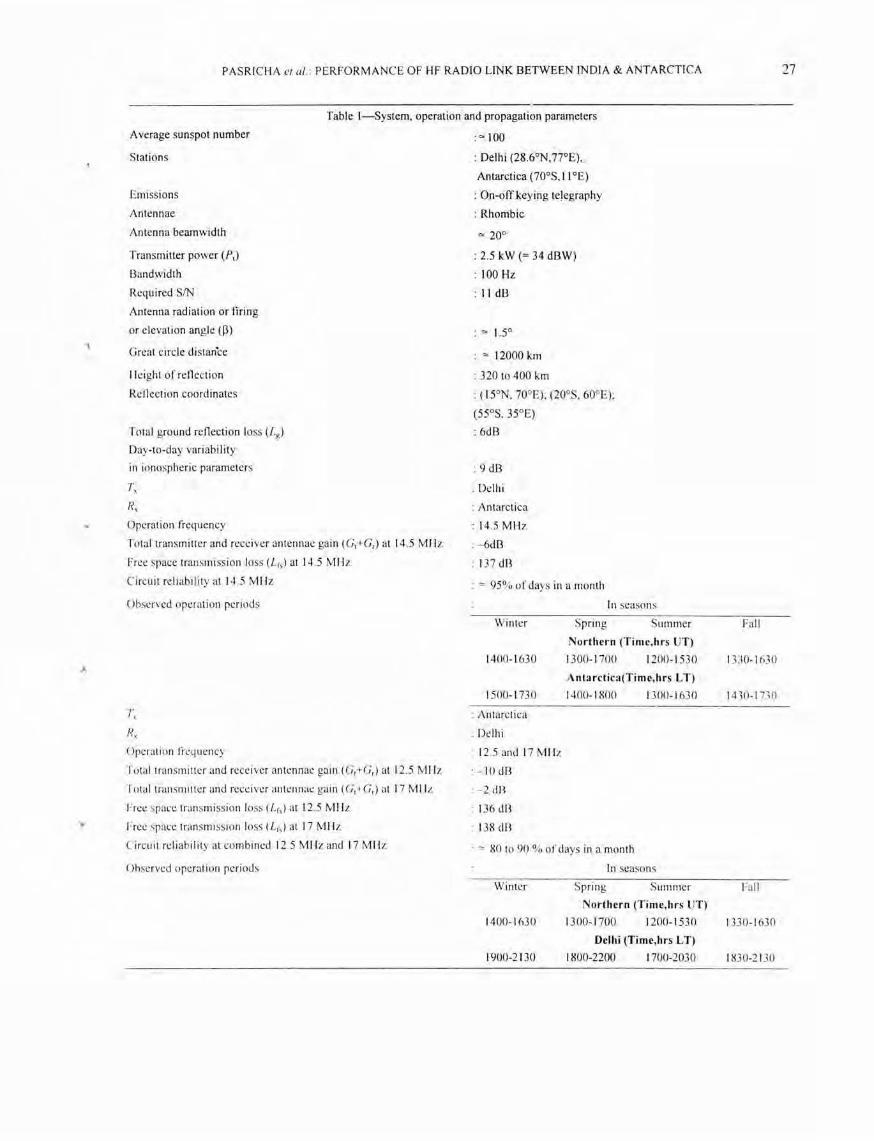
The characteristics of radio transmiss ion/reception from/at stations Delhi (28.6DN,77°E)/ Antarctica (700S, I 1 DE) are listed in Table I. The operation periods of the radio link during the seasons (Northern) of 1988-89 are the following: Spring (Mar.-May 1988), 1300 - 1700 hrs UT; Summer (.June - Aug.
PASRICHA el at. PERFORMANCE OF HF RADIO LINK BETWEEN INDIA & ANTARCTICA
Table I-System, operation and propagation parameters
A verage sunspot number
Stations
Emi ssions
Antennae
Antenna beam width
Transmitter power (P,)
Bandwidth
Rcquired SIN
Antenna radiati on or firing
or elevation angle (p)
Great circle distan'ce
Hcight of reflecti on
Refl ection coordinates
Total ground rcfl ection loss (L g)
Day-to-day vari ability
in ionospheric parameters
Tx
~,
Operati on frequency
Totaltransmittcr and rece iver antennae ga in (C,+Cr ) at 14.5 MH z
Free space transmi ss ion loss (Lfs) at 14.5 MH z
Circuit reli abil ity at 14 .5 MH z
Observed operati on periods
T,
R, Operat ion freq uency
Tota l transmittcr and receiver antenn ae gain (C,+Cr) at 12.5 MHz
To tal transmitter and rece iver antenn ae gain (C,~ C r ) at 17 Mllz
Free space transmi ssion loss (Lrsl at 12.5 MHz
Free space transmission loss (Lrs) at 17 MH z
Circuit rcli ab ility at combi ncd 12.5 MH z and 17 MH z
Observed operat ion pe ri ods
: 0< 100
: Delhi (28 .6°N,77°E),
Antarctica (700S, I 10E)
: On-off keying telegraphy
: Rhombic
: 2.5 kW (= 34 dBW)
: 100 Hz
: II dB
0< 12000 km
: 320 to 400 km
: (WN, 700E); (200S, 600E):
(55°S, 35°E)
:6dB
9 dB
: Delhi
: Antarctica
: 14.5 MHz
: -6dB
: 137 dB
: '" 95% of days in a month
In seasons
Winter
1400-1 630
1500-1 730
: Antarctica
: Delh i
: 12.5 and 17 MH z
: - 10 dB
: - 2 dB
: 136 dB
: 138 dR
Spring Summer
Northern (Time,hrs UT)
1300-1 700 1200-1530
Antarctica(Time,hrs L T)
1400-1800 1300-1 630
: '" 80 to 90 % of days in a month
In seasons
Winter Spring Summer
Northern (Time,hrs UT)
1400-1 630 1300-1700 1200-1 530
Delhi (Time,hrs L T)
1900-2130 1800-2200 1700-2030
27
Fall
I DO-1 630
1430-1 730
Fall
1330-1 63 0
1830-2 130

28 INDIAN J RADIO & SPACE PHYS, FEBRUARY 1999
1988), 1200 - 1530 hrs UT; Fall (Sep.-Nov. 1988), 1330 - 1630 hrs UT; and Winter (Dec.-Feb. 1988), 1400 - 1630 hrs UT. It must be pointed out that these operation periods refer to the total reception periods, irrespective of the choice of frequencies of operations at Delhi/Antarctica. A break-up in the operation period with respect to individual frequencies is not available. Moreover, the operation periods pertain to quiet ionospheric conditions and do not include periods in which HF communication is rendered ineffective due to ionospheric stonns. Smoothed 12-month running averaged sunspot numbers for the four seasons 111
1988-89 are roughly 80, 100, 125 and 145, respectively.
Whereas the reception frequency at Antarctica is 14.5 MH z, a set ofnIYo frequencies (12.5 MHz and 17 MHz) are received at Delhi. It must be pointed out that the observat ions on operation periods during different seasons are not separate ly available for the set of frequencies 12.5 MHz, 14.5 MHz and 17 MHz (Table I) . Moreover, the circuit reliability at 12.5 MHz and 17 MHz is also available as a combined c ircuit re·liabili ty at the two frequencies.
The great circle di stance between the two stations Delhi and Antarctica is about 12000 km. The propagati on of HF radio waves is theoret ica lly poss ible through a triple set o f reflecti ons at the F2-region of the ionosphere. The he ight of reflection, usi ng Eq.( 1) of Annexure A, varies from 320 to 400 km . The antenna radiation or elevation angle W), using Eq. (6) of Annexure A, is roughly 1.5° . The geographical coordinates of the three points of refl ect ion on the Delhi-Antarctica radio link are taken as (15°N, 70° E), (20oS,600E) and (55°S,35°E). The corresponding re lations between hours LT and UT are L T = UT + 5h, L T = UT + 4h and L T = UT + 2h, respectively. It may be noted that the first and third points of reflection are at a distance of about 2000 km from the stations Delhi and Antarctica, respectively.
At an e levation angle of 1.5° the total transmitter and receiver antennae ga in (Gt+Gr ) at 17 MHz, for instance, eq ua ls -2 dB . The tota l ground re flecti on loss (Lg) from the sea surface at an angle of 1.5° is 6 dB . The free space transmi ss ion losses Lfs at the freq uencies of 12.5, 14.5 and 17 MHz are 136 dB, 137 dB and 138 dB, respective ly. A daY-lo-day va riability of 9 dB accounts for the random variations in the reflection characteristics of the ionosphere. Various propagation parameters, such as, [3, (Gt+Gr),
Lg, Lfs, day-to-day variability, etc. are summarized in
Table I. For the sake of completeness, the dependence of antenna gain on the height of antenna, length of the side of antenna and radiated frequency is given in Annexure B.
3 Radio link reliability analysis at Delhi! Antarctica
Global maps of maximum usable frequency for a path length of 4000 km, called MUF( 4000)F2, reflected by the F2-region of the ionosphere, have been documented by CCIR3 [It is appropriate to note that CCIR is now known as ITU-R, where ITU-R stands for International Telecommunication Union -Radio communication.]. For a radio link of path length greater than 4000 km, as in the case of IndiaAntarctica I ink, two reflection points are marked, which are 2000 km from e ither of the two stations. The values of M UF( 4000)F2 for these two reflection poiilts, at a given hour, may be obta ined from CCI R3
.
The lowest of these two values of MUF(4000)F2 is taken as the maximum usable frequency (MUF).
The procedure to calculate MUF for a radio link of path length shorter than 4000 km is as tollows:
Global maps of foF2, a lso called MU F(0)F2, for a path length of 0 km, refl ected by the F2-region of the ionosphere, have also been documented by CCI R 3 .
The parameters MUF(4000)F2 and foF2 ca n be used to compute MUF(3000)F2, for a path length of 3000 km, refl ected by the F2-region of the ionosphere, us ing a nomogram given by CCIR' . The MUF, at a given hour, is the MUF(3000)f 2.
The MUF so-obtained, is the monthly-median MUF, and is expected to be ava ilable on 50 % of the days within a given month . It is further possible to compute the so-ca ll ed optimum traffic frequency (FOT), which is 15 % lower than MUF, through the relation: FOT = 0.85 x MUF. It has been found OLit from the experimenta l data that such an FOT is expected to be available fo r 90% of the days within a given month . The values of FOT for fOLir local hOLir blocks are · based upon the predictions of MUF(4000)F2 for R' 2= 100 as made by CCI R' . These values of FOT at both Antarctica and Delhi are given in Tables 2 and 3 [(a),(b)], respectively.
Atmospheric rad io noise for four local hour (L T) blocks, for receivers at Antarctica and Delhi , are obtained from CCIR4. These va lues of atmospheri c radio noise N(dBW) at 14.5 MHz, 12.5 M Hz and 17 MHz are also given in Tables 2, 3(a) and 3(b), respectively. Man-made and galactic: radio noise have, each, a value of - 160 d BW, at the freque nc ies and
PASRICHA el al. PERFORMANCE OF HF RADIO LINK BETWEEN INDIA & ANTARCTICA 29
Table 2--Estimates of available SIN and circuit reliability at Antarctica for sunspot number 100
(Tx - Delhi, Rx - Antarctica, Frequency - 14.S MHz, Bandwidth - 100 Hz)
Season Winter Spring Summer Fall
(Northern)
Four hour time block 07- 11 II-IS 15-19 07-11 II-IS IS-19 07-11 II-IS 15-19 07-11 11-1 5 15-19
(hrs UT)
Four hour time block 08-12 12-16 16-20 08-12 12- 16 16-20 08-12 12-16 16-20 08-12 12-1 6 16-20 (hrs L T, Antarctica)
Median at mospheric - 154 - 148 - IS9 - 159 - 154 - 159 - 162 - IS9 - 164 - 161 - IS4 - 164 radio noise (dBW)
Ionospheric 52-48 48-16 16-3 36-32 32-4 4-0 33-27 27-1 1-0 47-39 39-9 9-0 absorption loss (dB)
FOT (MHz) 18-18 18-17 17-15 26-31 31-25 25- 13 20-23 23-IS IS-7 23-24 24-22 22- 15
Available SIN(dB) ···7- - 3 - 3-29 29-42 9-13 13-41 41 -25 12-18 18-44 44-45 - 2-6 6-36 36-45
Ci rcuit - 18- - 14 - 14-18 18-31 - 2-2 2-30 30-34 1-7 7-33 33-34 - 13- - 7 - 7-25 25-34
reliability(dB)
Circuit reliability 12-17 17-90+ 90+-90+ 45-55 55-90+ 90+-90+ 52-72 72-90+ 90+-90+ 18-29 29-90+ 90+-90+
(%)
Theoretical opcration 1400-1900 1400-1830 1300-1500 1400-1 900 period(hrs UT) for ci rcuit reliability ~80%
Theoretical operation 1500-2000 1500-1930 1400-1600 1500-2000
period(hrs L T, Antarctica) for circuit reliability ~ 80%
Notes: (i) A constant value of atmospheric radio noi se (N) of - 160 dBW is used in the calculations.
(ii) C ircuit reliabilit~ 90+ % means ~ 90 %.
local hours under consideration4. A relative
comparison of different radio noises shows that atmospheric radio noise equals or dominates over man-made/ga lactic radio noise at both Antarctica and Delhi . Constant values of atmospheric radio noise of - 160 dBW, ·- 145 dBW and - 153 dBW at 14.5 MHz, 12.5 MHz and 17 MHz, respectively, are adopted in the present calculations.
The ionospheric absorption loss Lj(dB) needs to be individually evaluated at the local hours of the po ints of reflection on the radio link . The values of ionospheric absorption loss at 14.5 MHz, 12.5 MHz and 17 MHz, in four local hour blocks, are given in Tables 2, 3(a) and 3(b), respectively. The total system loss Lt(dB) is given as
L{= Lrs+Lj+Lg-Gt-Gr
The HF signal S(dBW) at the receiver is given as
S( dB W)=Pt( dBW) -Lt( dB).
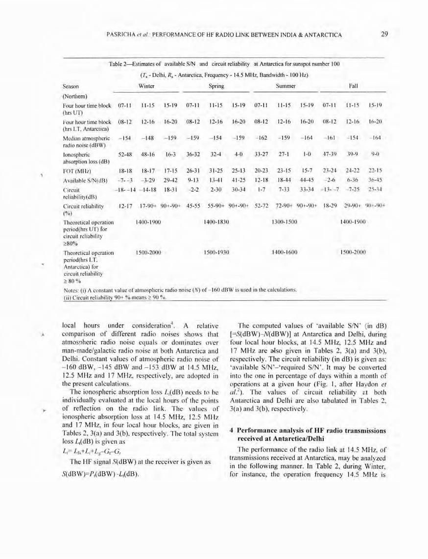
The computed values of ' available SIN ' ( in dB) [=S(dBW) - N(dBW)] at Antarctica and Delhi , during four local hour blocks, at 14.5 MHz, 12.5 MHz and 17 MHz are a-Iso given in Tables 2, 3(a) and 3(b), respectively. The circuit reliability (in dB) is given as: 'ava ilable SIN'-'required SIN'. It may be converted into the one in percentage of days within a month of operations at a given hour (Fig. I , after Haydon et al. 2
). The values of circuit reliability at both Antarctica and Delhi are also tabulated in Tables 2, 3(a) and 3(b), respectively.
4 Performance analysis of HF radio transmissions received at AntarcticalDelhi
The performance of the radio link at 14.5 MHz, of transmissions received at Antarctica, may be analyzed in the following manner. In Table 2, during Winter, for instance, the operation frequency 14.5 MHz is

30 IND IA J RADIO & SPACE PHYS, FEBRUARY 1999
Table 3(a}-Estimates of ava ilab le SIN and circuit re li ab ility at Delhi for sunspot number 100
(T, - Antarctica, R, - Delhi, Frequency - 12.5 MHz, Bandwidth - 100 Hz)
Season Wi nter Spring Su mmer Fall
(Northern)
Four hour time 07-11 11-15 15-1 9 07- 11 11-1 5 15-1 9 07-11 11-15 15-1 9 07-11 I 1-1 5 15-1 9 block (hrs UT)
four hour timc 12- 16 16-2 0 20-24 12- 16 16-20 20-24 12-1 6 16-20 20-24 12-1 6 16-20 16-20 block (hrs LT, Delhi)
Median - 144 - 142 - 149 - 147 - 140 - 144 - 147 - 140 -- 144 - 149 - 144 - 147 a tmospheri c radio noise (d13W)
Ionospheric 65 -65 65-25 25-5 44-44 44-8 8-0 40-40 40-3 3-0 58-56 56- 14 14-0 absorption loss (dB)
FOT (MHz) 18- 18 18-1 7 17- 15 26-3 1 31 -25 25-13 20-23 23-1 5 15-7 23-24 24-22 22 -1 5
Availab le SIN (d13 ) - 38- - 38 - 38- - 2 2-22 - 17- - 17 - 17-1 9 19-27 - 13- - 13 - 13-24 24-27 - 3 1- - 29 - 29·· 13 13-27
C ircuit re li ab ili ty --49- --49 --49- - 9 - 9-11 - 28- - 28 - 28-8 8-16 - 24- - 24 - 24-1 3 13-16 --42 - --40 --40-2 2-16 (dB)
Circuit reli abi lity 10- 10 10-2 1 2 1-85 10-10 10-75 75 -90+ 10-10 10-87 87-90+ 10- 10 10-55 55-90 (% )
Thcoretical 1600-1 900 1500-- 1600 ISOO- 1900 operat ion period (hrs UT) for ci rcuit
reliabi li ty ::O:80%
Theoretical 2 100-0000 2000--2100 2300--0000 operat ion period (hrs LT.Dclhi ) for ci rcui t reli ab il ity
::0:80%
Notes: ( i) A constant value ofatillospheric rad io noise (N) of - 145 dl3W is used in the ca lcul ations.
(ii) Ci rcuit re li ab ili ty 90+ % means::O: 90 %.
30 CIRCUIT RELiAB ILiT Y(%)
20
tIl r--- 90 "0
r- IO I- 8 0 f-
::J r--- 70
iii - 60 <X 0 ...J W
4 0
a:
f-
:> -10 u a: ~----
20
--u ~ -20 _'0
1----
-30 3 !5 10 1!5 20 25 30
FREQUENCY, MHz
f ig. I - Set of curvcs to convert circuit reliability (d!3) into circuit reliab ility (%) at different frequencies of operation (After IIaydon er a/2 )
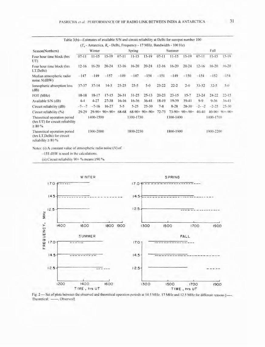
a lways less than FOT in the period 0700-1900 hrs UT. Further, the c ircuit re liability (%) is greater than 80 % in the period 1400-1 900 hrs UT, Thus, the period from about 1400 to 1900 hrs UT is considered as the theoretical period of operation. In this manner, the theoretical periods of operation for the seasons Spring, Summer and Fall are obtained as 1400-1830 hrs UT, 1300- 1500 hrs UT and 1400-1900 hrs UT, respectively. These theoret ical operation periods, in different seasons, depict a circuit reliabi lity of more than 80 %. The overlapping of observed and theoretical operation periods at 14.5 MH z is analyzed in Fig. 2 . The observed operation periods appear to match the theoretica l operation periods for the different seasons. In general , lhe HF communication appears to occur for about half to one hour earlier than the theoretica l operation periods.
The performance of the radio link at 12.5 MHz, for transmi ss ions received at Delhi , is given in Table
PASRICHA el 0 1. PERFORMANCE OF HF RADIO LINK BETWEEN INDIA & ANTA RCTICA 31
Table 3(b}-Estimates of available SIN and circuit reli ability at Delhi for sunspot number 100
(T. - Antarctica, Rx - Delhi. Frequency - 17 MHz. Bandwidth - 100 Hz)
Season(Northern) Winter Spring Summer Fall
Four hour time block (hrs 07-11 II-IS 15-1 9 07-11 II-IS 15-19 07-11 11-15 15-1 9 07-11 II-IS 15-1 9 UT)
Four hour time block (hrs 12-16 16-20 20-24 12- 16 16-20 20-24 12-16 16-20 20-24 12-16 16-20 16-20 L T.Delhi)
Median atmospheric radio - 147 - 149 - 157 - 149 - 147 - 154 - 151 - 149 - ISO - 154 - 152 - 154 noise N(d BW)
Ionospheric absorption loss 37-37 37-14 14-3 25-25 25-5 5-0 23-22 22-2 2-0 33-3 2 32-5 5-0 (dB)
FOT (MHz) 18-18 18-1 7 17-15 26-31 31-25 25-13 20-23 23-15 15-7 23-24 24-22 22 -1 5
Avai lable SIN (dB) 4-4 4-27 27-38 16-16 16-36 36-41 18-19 19-39 39-41 9-9 9-36 36-41
Ci rcuit reliability (dB) -7- - 7 - 7-16 16-27 5-5 5-25 25-30 7-8 8-28 28-30 ' - 2- - 2 - 2-25 25-30
Circuit reliabi lity (%) 29-29 29-90+ 90+-90+ 68-68 68-90+ 90+-90+ 72-73 73-90+ 90+-90-"- 40-40 40-90+ 90+-90+
Theoretical operation period 1400-1500 1300-1 730 1300-1400 1400-1 700 (hrs UT) for circuit reli ability ~ 80%
Theoretical opaation period 1900-2000 1800-2230 1800-1 900 1900-2 200 (hrs L T,Delhi) fo r circuit reli ability ~ 80 %
No!t:s: (i) A constant vallie of atmospheric radio noise (N) of
- 153 dBW is used in the calculati ons.
(i i) Circuit reliability 90+ % means ~90 %.
W INTER SPRING
17 .0 ·r------- 17 .0 - -
14 .5 ____ ____ _ __ _ __ __ _ _____ _ 14 .5 ______________ _________ _ ___ _
12 .5 12 .5 --- -- - --- -- - --~ -
N I ~
- -.J
>- 1400 1600 1800 1900 1300 1500 1700 1900 u z UJ
SU MMER ;:) FALL 0 UJ 170 ----.- 170 ---- --------- ---0: lJ..
14.5 14 .5 ------------ --------~ -
12. 5 -- - --- 12.5 - ----
---l
1200 14 00 1600 1300 1500 1700 1900 T IM E, hrs UT TIME,hrsUT
Fig. 2 - Set of plots between the observed and theoretical operation periods at 14.5 Mil l., 17 MHz and 12.5 MHz fo r different ~easons l-----, Theoreti cal ; --, Observed]

32 INDI AN J RADIO & SPACE PHYS, FEBRUARY 1999
3(a). In Table 3(a), during Summer, for the approximate period 1500-1600 hrs UT, the operation frequency 12.5 MHz is less than the FaT and the circuit reliability (%) is greater than 80 %.
Thus, the theoretical period of operation for Summer is obtained as 1500-1600 hrs UT. In Spring and Fall , the theoretical operation periods are obtained as 1600-1900 hrs UT and 1800-1900 hrs UT, respective ly. In Winter, no theoretical operation period appears to exist. The performance of the radio link at 17 MHz for transmissions received at Delhi, is given in Table 3(b). · The theoretical periods of operation for Winter, Spring, Summer and Fa ll are obtained as 1400-1500 hrs UT, 1300-1730 hrs UT, 1300-1400 hrs UT and 1400-1700 hrs UT. respectively. The theoretical operation periods appear to match the observed operation periods for Spring and Fall (Fig. 2). In Winter, however, HF communication appears to occur for about two hours, one hour more than the theoretical operation period (Fig. 2). Further, in Summer, the theoretical operation period for HF communication at the two frequencies 12.5 MHz and 17 MHz (together) roughly approaches the observed operation period (Fig. 2).
5 Summary and cOJ/lclusion
The trad itional method of communication is the HF commun ication via the F-region of the ionosphere. Through a proper selection of operation frequencies and periods, the Hf communication can become a highly reliable mode of communication during the quiet ionospheri c conditions. The HF communication to a remote place like Antarctica can be treated as an alternative mode to the modern , but expensive, satellite mode of communication.
During the ri s ing part of the so lar activity, two frequencies, namely, 14.5 MHz for reception at Antarctica and, 12 .5 MHz and 17 MHz for reception at Delhi are used. The cho ice of frequencies, as we ll as the operational periods, were determined by a desi re to use the FaT during that period at the point of reflection closest to Antarctica and by the selection of a circuit re liability greater than, say, 80 % . The operational frequency rece ived at Delh i was predominant ly 17 MHz during Spring, Summer and Fa ll (Northern) . An additional lower frequency of 12.5 MHz was necessary to strengthen communication during Summer (Northern). The operation frequency rece ived at Antarctica is 14 .5 MHz during Spring, Summer and Fall (Northern ). During Winter (Northern), both at 14.5 MHz and 17
MHz, the theoretically deduced and observed operation periods do not appear to match . The operation frequency (i.e. , 17 MHz) is higher at Delhi than at Antarctica (i .e., 14.5 MHz). This is due to higher levels of radio noise at · Delhi than at Antarctica. In general, the theoretically deduced operation period is a few hours between 1300 and 1900 hrs UT during differe;nt seasons. However, the observed operation period is between 1200 and 1700 hrs UT. The upper hour of 1900 hrs UT of the theoretical operation period corresponds to about midnight at Delhi . It appears that no HF communication was observed beyond about 1700 hrs UT due possibly to late even ing hours at Delhi. It may be mentioned that the configuration of the present circuit is rather unusual. The nO/them control point lies near the equatorial anomaly and lTlay be affected by the steep ionization gradients found there. A discussion 011 the possible role of latitudinal gradients in e lectron density on HF propagation is given in Annexure C.
The performance analysis of the HF radio link presented here may he lp in the design of radio circuit parameters for communication to Antarctica under a variety of solar activity conditions.
Acknowledgements
The authors acknowledge the discussion they had with Dr A B Ghosh on the implications of ray tracing in the presence of latitudinal gradients in the ionosphere a'nd with Dr P K Banerjee on antenna design considerations.
References
Barghausen A F, Fi nney J W, Proctor L L & Schultz L D, Predicting long-term operational parameters of highfrequency sf...y-wave telecommunication systems, ESSA Tech Rep ERL I I()-ITS 78. Insti tute for Telecommunication Sciences, I3oulder, 1969.
2 Haydon J C, Lucas D L & Hanson R A, Technical considerations ill the selection of optimum freq uencies for high-frequency sky wave communicarion services, ESSA Tech Rep ERL IJ3-ITS 81, Institute for Tdccommunieation Sc iences, Boulder, 1969 .
3 COR, CCIR atlas of ionospheric characteristics, Rep 340, Internationa l Rad io Consultative Committee, Geneva, 1983 .
4 CeIR, Characteristics and applications of atmospheric radio noise data, Rep 322-2, Modified-F, In te rnational Radio Consultative Committee, XVlth Plenary Assembly, Dubrovnik. 1986.
5 Bradley P A & Dudeney J R. J Atmos & Terr Phys (UK) , 35 ( 1973) 213 I.
6 IPS. Handbook for lise with ionoJpheric prediction services, Series 115, Ionospheri c Pred iction Service Division, North Sydney, Austral ia. 1969.
)

<,
PASRICHA c/ al. PERFORMANCE OF HF RADIO LINK BETWEEN INDIA & ANTARCTICA 33
7 Thourel L, The Antenna (Chapman & Hall, London) 1960, p. 150.
8 Jones R M, A three-dimensional ray tracing computer program. ESS.4. T~ch Rep IER 17-ITSA 17, U.S. Government Printing Office, Washington D.C., 1966.
9 Davies K, Ionospheric Radio Propagation. National' Bureau of Standards Monograph 80, National Bureau of Standards, Washington, 1965, p. 186.
10 Goodman J M, HF Communication-Science & Technology (Van Nostrand Reinhold, New York) 1992, p. 259.
Annexure A
Some relevant formulae
The height of the reflecting F2-region, which is assumed to be the height of maximum electron density (hmF2), is given in terms of MUF(4000)F2, foF2,foE and RI2 through the following relations3
,5:
,
hmF2 = [14901 {M(3000)F2+8 M} ]- 176 ... (I)
where,
M(3000)F2 = MUF(4000)F2 1 (1.I>1QF2)
8M= [{0 .18/(X-1.4)} + {0.096(RI 2-25)/ 150}]
JoF2 = MUF(0)F2
X= JoF2/foE, or 1.7, whichever is larger
RI2 = 12-month running averaged sunspot number = 0 or 100 (assumed)
JoE=Reflecting frequency corresponding to the height of maximum electron dens ity of E-region, given in terms of solar zen ith angle and RI 2 [see CClR' for solar zen ith angle contours and .foE nomogram]
The elevation angle W) to the reflecting height (assumed) hmF2 is given in terms of angle of incidence (~) at hmF2, geocentric angle (8) and num ber of reflections or hops (n) through the relations:
cos (3 = (I +hmF2Ia) sin ~
where,
tan ~ = a sin 81 [hv+a( l--cos 8)
8° = r(in km) 1 (n x 222.4)
Single hop path length = 4000 km
N '" rein km) 1 4000
hv '" hmF2
"" 320-400 km
.. . (2)
.. . (3)
... (4)
a = 6370 km
r = 12000 km between India and Antarctica
n = rein km) 1 4000 = 3
(3 "" 1.5°
... (5)
... (6)
The relations for number of reflections or hops (n)
and elevation angle «(3) need to be modified under other solar activity conditions, say, under minimum solar activity. This is in view of the fact that hmF2 is observed to decrease with decrease in sunspot number. Thus, hv ( "" hmF2) is reduced . Also, in view of Table 3 of IPS6, single hop path length, n, and (3 need to be modified as:
"" 320 k[ll
(ii ) Single hop path length = 2400 km
(iii) n = rein km) 1 2400 = 5
(iv) (3 "" 10° A schematic diagram illustrating the link geometry
parameters (3, ~, 8 and hv is given in Fig.3.
o
e
Fig. J - Schematic diagram illustrating the link geometry parameters p, cjl, 0 and hv

34 INDIAN J RADIO & SPACE PHYS, FEBRUARY 1999
Annexure B
It is generally experimentally difficult to obtain antenna ga in dependence on both height of the antenna (h) and length of the side of the antenna (1) fo r grazing values ([3) of about 1°. Theoretically, the antenna gai n for a rhombic antenna, for instance, has a height factor (A,,) and a length factor (A,). They are given as:
A" = sin(h!)c sin [3)
and,
A, = sin2 /IA(I - sin a cos [3), respectively.
Here, A is the wavelength and a the half of the obtuse angle of the rhombic .. Now, typical values of various parameters are: A"" 20 m, h = 15 m, 1= 50 m, a = 60° and [3 = 1°. The values of A" and A, are 0.013 and 0.108, respectively. These values are rather small in magnitude. They also suggest that both h and I need to be increased to atta in grazing va.lues of [3 = 1° (Ref. 7). In genera l, antenna ga in increases with radiated frequency. For instance, antenna gain for a rhombic antenna at the frequencies of 12.5 MHz, 14 .5 MHz and 17 MHz are about -5 dB, -3 dB and -I dB, respectively.
Annexure C
The CCI R' document may be used to compute iatitudinal gradients in foF2, and, hence, in electron density, aci'oss latitudes 15°N and 200S. For instance, typical va lues of percentage changes in electron density, across latitudes 15°N and 200S, at 1400 hrs UT for the periods of Winter, Spring, Summer and Fall are -40%, - 30%, -70% and -20%, respectively (The minus sign indicates a decrease in electron density.).
A three-di mensional ray tracing algorithm, such as that of Jones8
, may be used to trace Hf ray trajectories from transmitter at Antarctica (700S) to receiver at Delhi (28°N). The latitudinal gradients in electron density may be indirectly incorporated th rough the vertical profiles of electron density
8000 Km
EARTH
associated with the three points of reflection . However, such a detailed ray tracing procedure has not been employed in the present study. Instead, some of the results of Davies? have been used to speculate on the likely mode of HF propagation across 15° N and 20° S section of the radio li nk between India and Antarctica.
Davies? studied a rad io link bctween 20° Nand 32° S at a frequency of 25 MHz. The ray tracing was performed across the magnetic eq uator at 75° W longitude meridian. An important result of thi s ray tracing study is that the rays fired at an initial angle of about I ° were received at an angle of about 10° in the presence of latitudinal gradicnts in electron density. In the present study the lat itudinal gradients in the
INDIA (2eON)
Rl(
Fig. 4 - Schematic diagram o f ray trajectories fo r a three hop propagation via the F-region of the ionosphere. The transmitter (7: ) and rr('r;wr (R .. ) il r c il l Antarctica (700S) and India (28°N)

PASRI CHA e/ al.: PERFORMANCE OF HF RADIO LINK BETWEEN INDIA & ANTARCTICA 35
observed values of electron density are found to be important across 15° Nand 20° S section of the radio link at roughly 70° E longitude meridian. The frequencies of HF propagation vary between 12.5 MHz and 17 MHz. The ray tracing results of Davies9 are adopted for this section of the radio link, as well. Thus, a schematic diagram of the tracing of ray trajectories in three hops, fired at an initial angle of about 1°, is given in Fig. 4. The latitudinal gradients in electron density, across 15° Nand 20° S, are likely to reduce the triple hop propagation to essentially double hop propagation, as shown in Fig. 4. The HF propagation "across 15° N and 20° S section of the radio link is likely to be chordal mode of propagation across the magnetic equator, without ground retlections1o
. In the present
study, to a first approximation, the theoretical three hop propagation is used to obtain estimates of. ~ircuit reliability at the two stations. Thus, the estimates of circuit reliability are likely to be underestimated
The southern control point of the circuit lies near the auroral oval and can be expected to experience high absorption at times, as well as a number of other detrimental effects. In general , high latitude circuits are difficult partly because of absorption and some deep and highly variable fading on operating frequencies . These effects have been attributed to particle activity. Such phenomena will be important for other high latitude circuits making the general conclusions about HF for Antarctic communications rather suspect.