performance analysis of axial field permanent … · magdy khaled, mohamed kamal ahmed, m elwany...
TRANSCRIPT

http://www.iaeme.com/IJEET/index.asp 31 [email protected]
International Journal of Electrical Engineering & Technology (IJEET)
Volume 10, Issue 4, July -August 2019, pp. 31-42, Article ID: IJEET_10_04_004
Available online at http://www.iaeme.com/IJEET/issues.asp?JType=IJEET&VType=10&IType=4
ISSN Print: 0976-6545 and ISSN Online: 0976-6553
Journal Impact Factor (2019): 9.7560 (Calculated by GISI) www.jifactor.com
© IAEME Publication
PERFORMANCE ANALYSIS OF AXIAL FIELD
PERMANENT MAGNET GENERATOR
Magdy Khaled, Mohamed Kamal Ahmed, M Elwany and Mahfouz Shalaby
Electrical Power and Machines Department, Faculty of Engineering,
Al-Azhar University, Cairo, Egypt
ABSTRACT
Axial Field Permanent Magnet (AFPM) synchronous generators are broadly
connected for the little size power wind turbine this is ascribe to its powerful thickness
per unit load than the conventional synchronous generator. It is a circle molded rotor
and the stator structures. In this paper, examine the execution of both AFER-NS and
AFIR-S generators having double side's slotted stator core is accomplished to improve
the output generation characteristics. The electromagnetic plan examination was done
to expand the power density. The enhancements design structure optimizations of the
rotor pole-arc ratio of permanent magnet are proficient to increase output power and
to decrease cogging torque. The output performances of AFER-NS and AFIR-S
generators are associated with each other.
Keywords: (AFPM), AFER-NS, AFIR-S
Cite this Article: Magdy Khaled, Mohamed Kamal Ahmed, M Elwany and Mahfouz
Shalaby, Performance Analysis of Axial Field Permanent Magnet Generator,
International Journal of Electrical Engineering & Technology, 10(4), 2019, pp. 31-42.
http://www.iaeme.com/IJEET/issues.asp?JType=IJEET&VType=10&IType=4
1. INTRODUCTION
The Axial Flux Permanent Magnet (AFPM) synchronous machines have been developing in
fame and have gotten an expanding measure of consideration in direct drive wind control
application [1]. It is creating magnetic flux in the axial direction, rather than the radial
direction. There are two sorts of AFPM machines, AFER-NS (Axial Field External Rotor-
Non-Slotted) and AFIR-S (Axial Field Inner Rotor-Slotted). Contrasted and RFPM machines,
the upsides of AFPM machines can be outlined as pursues:
simple winding,
low cogging torque and noise (in slotless machine),
short axial length,
higher torque/volume ratio”.
In any case, the hindrances of AFPM machines in examination with RFPM machines are
as per the following:

Magdy Khaled, Mohamed Kamal Ahmed, M Elwany and Mahfouz Shalaby
http://www.iaeme.com/IJEET/index.asp 32 [email protected]
lower torque/mass proportion
larger external distance across, extensive measure of PM and basic precariousness (in slotless
machine)
difficulty to keep up air gap in extensive distance across (in opened machine)
difficulty underway of stator core (in opened machine).
The opportunity and potential of AFPM machines for large-scale direct-drive wind
turbines have been considered, and some varied structures of AFPM machines with surface-
mounted PM have correspondingly been offered in some references [2,3,4].
The non-slotted single stator double rotor is a typical structure of AFPM machines, which
is often referred to as a Torus machine, as displayed in Figure . (1) [5]. The two rotor plates
are made of mild steel and have surface-mounted PM to deliver an axially directed magnetic
field in the machine air gaps. The machine stator includes a non-opened toroidally twisted
strip-iron center that conveys a three-phase winding in a toroidal manner by methods for
concentrated coils.
Figure 1 Axial Field External Rotor-Non Slotted AFER-NS
The non-slotted, toroidal-stator AFPM generator has been likewise examined with a few
points of interest, for example, the lightness, the smallness, the short hub length, the
reasonable coordination with the motor and others by Spooner and Chalmers [5] and Wu et al.
[6,7], the machine's short axial length will in general give it a high capacity to weight
proportion. Parviainen [8] has interduce an analytical method to achieve the preliminary
design of a surface-mounted, low-speed, slotted AFPM machine with one-rotor two-stator
configuration, as exposed in Figure . (2).
The performance and structure amid the low-speed radial flux and axial flux PM machine
keep on similarly associated in the power range from 10 to 500 kW at 150–600 rpm [8].
Moreover, five different topologies of AFPM machines, a double-stator slotted type, a
double-rotor slotted type, a single-sided AFPM with stator equilibrium, a single-sided AFPM
with rotor equilibrium and a non-slotted single-stator double-rotor (Torus machine), have
been examined and accompanying with RFPM machines by Chen et al. [2]”.

Performance Analysis of Axial Field Permanent Magnet Generator
http://www.iaeme.com/IJEET/index.asp 33 [email protected]
Figure 2 Axial Field Inner Rotor-Slotted AFIR-S double-stator single-rotor configuration
According to [2], the two-sided AFPM machine is superior to the one-sided AFPM
machine; however, one-sided constructions use less copper and have a lower conduction loss.
The Torus construction is simple; however, it needs extra magnet weight since of the
existence of the additional air gap for cooperative stator windings.
As the power rating increases, both air gap and air gap reluctance turn out to be higher,
consequently that this structure is more appropriate for small power rating wind generators. In
accumulation, the possible application of soft magnetic composite (SMC) material practical to
the low speed, direct-drive axial flux PM wind generator was as well considered by Chen et
al. Relative design studies were showed on different configuration PM generators with both
lamination core and SMC core [9].
2. ELECTROMAGNETIC STRUCTURE ANALYSIS OF THE (AFPM)
GENERATOR
To examine the electromagnetic structure design and the design enhancement of AFIR-S
generator for wind turbine initially, the electromagnetic structure design investigation is
cultivated to expand the power density of the recommended AFIR-S generator. Besides, the
design improvement of the shaft circular segment proportion and the perpetual magnet skew
point of rotor to build the yield created voltage and to decrease the cogging torque. At long
last, the output performances of AFER-NS and AFIRS generator are contrasted and one
another.
Figure (3) indicates two structure kinds of AFPM generators. Figure . (3a) is the structure
of the by and large utilized traditional AFER-NS generator.
It has two outer plate rotors at the two sides and has the non-slotted stator without stator
core. The winding turns are twisted in the plastic bobbin and shaped by the epoxy. AFER-NS
has been utilized for small wind turbine due to straightforward structure, wide speed range
and essentially no cogging torque creation.
Nonetheless, its produced voltage is low attributable to extensive reluctance by the long
air-gap. It can likewise cause the power transformation productivity drop and the cost
increment of circuit setup in AC/DC converter and DC/AC inverter. Figure . (3b)
demonstrates the structure of AFIR-S generator proposed in this section.
The rotor having permanent magnets is located between the stators having the opened
steel core. This structure of AFIR-S generator can enhance the output power density per the
Magdy Khaled, Mohamed Kamal Ahmed, M Elwany and Mahfouz Shalaby
http://www.iaeme.com/IJEET/index.asp 34 [email protected]
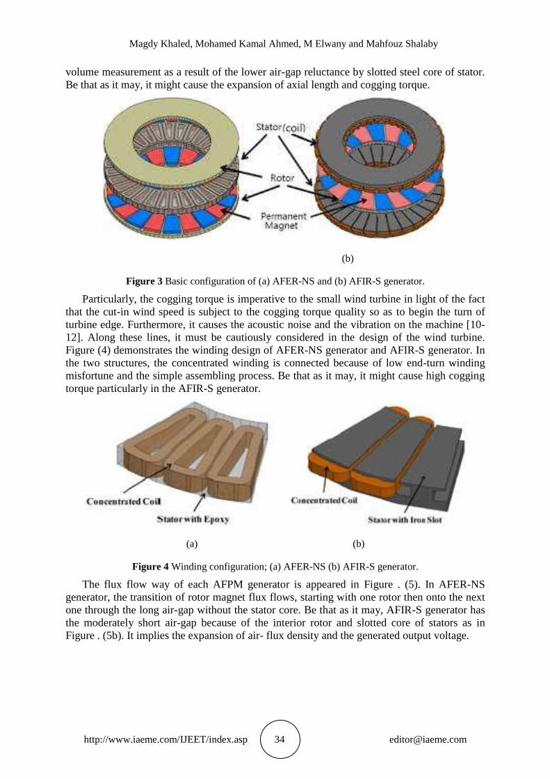
volume measurement as a result of the lower air-gap reluctance by slotted steel core of stator.
Be that as it may, it might cause the expansion of axial length and cogging torque.
(b)
Figure 3 Basic configuration of (a) AFER-NS and (b) AFIR-S generator.
Particularly, the cogging torque is imperative to the small wind turbine in light of the fact
that the cut-in wind speed is subject to the cogging torque quality so as to begin the turn of
turbine edge. Furthermore, it causes the acoustic noise and the vibration on the machine [10-
12]. Along these lines, it must be cautiously considered in the design of the wind turbine.
Figure (4) demonstrates the winding design of AFER-NS generator and AFIR-S generator. In
the two structures, the concentrated winding is connected because of low end-turn winding
misfortune and the simple assembling process. Be that as it may, it might cause high cogging
torque particularly in the AFIR-S generator.
(a) (b)
Figure 4 Winding configuration; (a) AFER-NS (b) AFIR-S generator.
The flux flow way of each AFPM generator is appeared in Figure . (5). In AFER-NS
generator, the transition of rotor magnet flux flows, starting with one rotor then onto the next
one through the long air-gap without the stator core. Be that as it may, AFIR-S generator has
the moderately short air-gap because of the interior rotor and slotted core of stators as in
Figure . (5b). It implies the expansion of air- flux density and the generated output voltage.

Performance Analysis of Axial Field Permanent Magnet Generator
http://www.iaeme.com/IJEET/index.asp 35 [email protected]
Figure 5 Flux movement track; (a) AFER-NS and (b) AFIR-S generator.
3. ELECTRO MAGNETIC TORQUE AND EMF FOR AFPM
MACHINE
The magnetic flux waveform per pole excited by the rotor magnet could specified by [12]:
(1(
wherever Φpole is flux per pole, αi is the ratio of the average value to the peak value of the
magnetic flux density in the air-gap, p is the number of magnetic poles, Do is outer diameter
of magnet, Di is inner diameter of magnet and Bmg is maximum flux density in the air-gap.
The torque fashioned by the stator current and the rotor magnet is considered as [12, 13].
(2(
anywhere m1 is the number of phases, Ia is line current, N1 is the number of turns per
phase, kw is winding factor, Bg is magnetic flux density in air-gap and kd is defined as ratio of
the inner diameter to outer diameter of magnet. The factor kd influences maximum torque and
torque density. It was confirmed that the maximum torque is obtained at:
√ (3(
The RMS value of the induced EMF in each phase Ef is gotten as [13].
√
(4(
wherever ns is the rotation speed of the motor per second. From (1) to (4), the output
power PR can be found as:
∫
(5(
wherever η is the efficiency of this machine, EPK is the peak value of emf and IPK are the
peak value input current. The proposal parameters of each AFPM generator are as in Table
(1). As denoted in Table (1), the design assessment was completed under the same volume

Magdy Khaled, Mohamed Kamal Ahmed, M Elwany and Mahfouz Shalaby
http://www.iaeme.com/IJEET/index.asp 36 [email protected]
dimensional situations, e.g. outer diameter, inner diameter, total axial length, air-gap length
and winding turns of each AFER-NS and AFIR-S generator.
Table (2) displays the initial design results of each type‟s generator. Under the same
electromagnetic volume dimension, the output power of AFIR-S generator is nearly two times
of the conservative AFER-NS generator. It is due to the reduction of reluctance of flux paths
between stator and rotor in AFIR-S generator having stator core steel. Nonetheless the
cogging torque is mostly generated by the stator core slot and rotor magnet flux in AFIR-S
generator. It should be minimized to obtain low cut-in speed of wind turbine.
Table 1 Parameters of AFER and AFIR-S generator.
Parameter AFER-NS AFIR-S
Outer-diameter (mm) 211 211
Inner-diameter (mm) 122 122
Axial-thickness of magnets (mm) 5 5
Total-axial length (mm) 30 30
Air-gap length (mm) 1.0 1.0
Number of Poles p 20 20
Number of stators 1 2
Number of rotors 2 1
Number of phases (m1) 3 3
Number of coils/phase (N1) 10 10
Number of slots (Ns) - 30
Number of turns (turns) 16 16
Coil diameter (mm) 1.02 1.02
Permanent magnet grade (NdFeB) 39UH(Br -1.2T) 39UH(Br -1.2T)
Core steel grade S18 S18
Table 2 Initial design results of AFER-NS and AFIR-S generators
Parameter AFER-NS AFIR-S
Rated speed (rpm) 600 600
Rated torque (Nm) 11.4 23.5
Input power(W) 716 1417
Output voltage (Vrms) 24 60
Output current (Arms) 8.7 7.6
Output power (W) 634 1380
Cogging torque (Nm pk-pk) - 7.2
4. COGGING TORQUE MINIMIZATION
The cogging torque is delivered by the air-gap reluctance variety between stator tooth, slots
and the flux of rotor magnet as the rotor turns. It is evaluated by the computation of absolute
energy stored variety noticeable all around air-gap as for the rotor position development.
Cogging torque Tcog can be composed as:
(6(
where, φg is the air-gap flux, R is the air-gap reluctance and θr is the precise rotor position.
Cogging torque can be a significant issue in AFIR-S generator not at all like AFERNS
generator not having the slotted steel core. Figure . (6) demonstrates the structure answers for
limit cogging torque at AFPM machines [13].

Performance Analysis of Axial Field Permanent Magnet Generator
http://www.iaeme.com/IJEET/index.asp 37 [email protected]
Figure 6 Design resolutions to minimize cogging torque in AFPM machines.
It tends to be accomplished by two habits; the structure adjustments of the stator side and
the rotor side. In any case, the design change of stator impacts the assembling procedure, for
example winding, stacking, etc. It causes the issue of assembling cost and profitability.
In the rotor design, the structure change of pole-arc segment and skew edge of rotor
magnet are the basic answers for limit cogging torque. The skew of magnet can't be connected
frequently due to the assembling issue of magnet. Then again, the magnet pole-arc segment
structure enhancement, as appeared in Figure . (7), can be a decent structure arrangement.
Figure 7 “Pole-arc ratio to pole-pitch of rotor magnets.”
Since cogging torque is emerged by the connection of the edges of magnet poles and the
stator slots, cogging torque is subject to the magnet pole-arc structure. The pole-arc segment
configuration may impact the flux of rotor magnet, and it likewise impacts the output
characteristics. Along these lines, the exchange off plan is required [12]. The magnet shaft
circular segment proportion αp of rotor magnet is characterized to as eq. (7):
Magdy Khaled, Mohamed Kamal Ahmed, M Elwany and Mahfouz Shalaby
http://www.iaeme.com/IJEET/index.asp 38 [email protected]
(7)
where, τp is the rotor pole pitch and τm is the magnet pitch. The optimal magnet pole-arc
ratio αpo for the smallest cogging torque in the radial field machine can similarly be practical
for AFPM machines as in eq. (8) [11].
(8)
wherever, N = Nc/2p, p is the pole pair number, Nc is LCM of the rotor pole numbers and
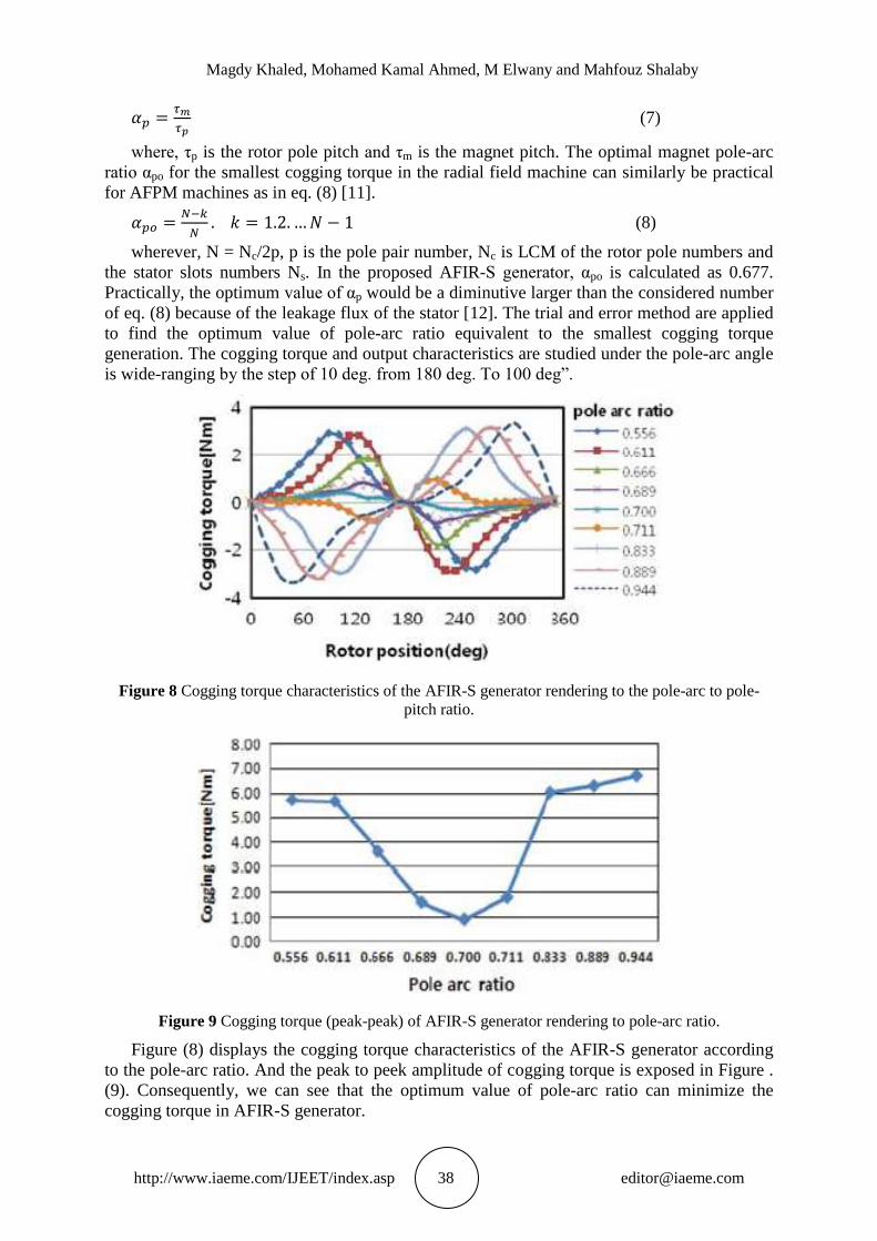
the stator slots numbers Ns. In the proposed AFIR-S generator, αpo is calculated as 0.677.
Practically, the optimum value of αp would be a diminutive larger than the considered number
of eq. (8) because of the leakage flux of the stator [12]. The trial and error method are applied
to find the optimum value of pole-arc ratio equivalent to the smallest cogging torque
generation. The cogging torque and output characteristics are studied under the pole-arc angle
is wide-ranging by the step of 10 deg. from 180 deg. To 100 deg”.
Figure 8 Cogging torque characteristics of the AFIR-S generator rendering to the pole-arc to pole-
pitch ratio.
Figure 9 Cogging torque (peak-peak) of AFIR-S generator rendering to pole-arc ratio.
Figure (8) displays the cogging torque characteristics of the AFIR-S generator according
to the pole-arc ratio. And the peak to peek amplitude of cogging torque is exposed in Figure .
(9). Consequently, we can see that the optimum value of pole-arc ratio can minimize the
cogging torque in AFIR-S generator.

Performance Analysis of Axial Field Permanent Magnet Generator
http://www.iaeme.com/IJEET/index.asp 39 [email protected]
5. PERFORMANCE COMPARISON OF AFER-NS AND AFIRS
GENERATOR
Figure (10) displays the examples of AFER-NS generator and AFIR-S generator having the
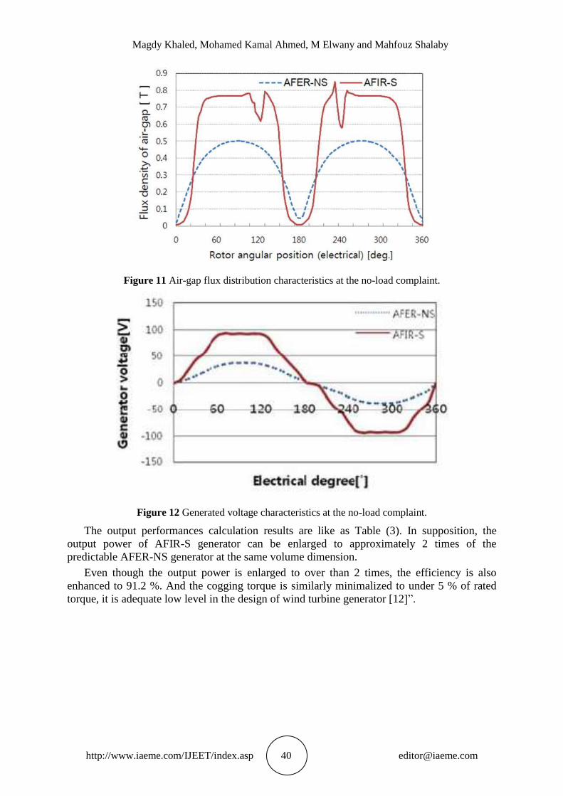
same electromagnetic volume. Figure . (11) demonstrations the air-gap flux density
distribution at the no-load state. The air-gap flux density of AFIR-S generator is improved by
53% than that of AFER-NS generator.
Figure 10 Prototypes of AFER-NS generator and AFIR-S generator having the similar
electromagnetic volume.
In the AFIR-S generator, the failure of air-gap flux is happened by the magnet dead zone
of rotor pole and the slot of stator core. The main deep of air-gap flux is caused by stator slot,
and the failure of air-gap flux during high flux density area is produced by the magnet dead
zone of rotor pole. Figure. (12) shows the no-load generated voltage of AFIR-S generator. As
exposed in Figure . (12), the generated voltage of AFIR-S generator is improved by 43.18
[Vrms] associated with AFER-NS generator and, the generated voltage waveform of AFIR-S
is trapezoidal waveform rendering to the air-gap flux waveform.
Magdy Khaled, Mohamed Kamal Ahmed, M Elwany and Mahfouz Shalaby
http://www.iaeme.com/IJEET/index.asp 40 [email protected]
Figure 11 Air-gap flux distribution characteristics at the no-load complaint.
Figure 12 Generated voltage characteristics at the no-load complaint.
The output performances calculation results are like as Table (3). In supposition, the
output power of AFIR-S generator can be enlarged to approximately 2 times of the
predictable AFER-NS generator at the same volume dimension.
Even though the output power is enlarged to over than 2 times, the efficiency is also
enhanced to 91.2 %. And the cogging torque is similarly minimalized to under 5 % of rated
torque, it is adequate low level in the design of wind turbine generator [12]”.

Performance Analysis of Axial Field Permanent Magnet Generator
http://www.iaeme.com/IJEET/index.asp 41 [email protected]
Figure 13 Comparison of the generated voltage and the output current characteristics at the full load
condition.
Table 3 Performance comparison at rated load and the same electromagnetic volume dimension.
Parameter AFER-NS AFIR-S
Rated speed (rpm) 600 600
Rated torque (Nm) 11.9 22.5
Input power(W) 747.7 1414
Output voltage (Vrms) 24 60
Output current (Arms) 9.0 7.1
Output power (W) 642.6 1288.7
Efficiency (%) 85.9 91.2
Cogging torque (Nm) - 0.795
Cogging torque / Rated torque (%) - 3.5
Torque ripple (%) 3.4 1.87
6. CONCLUSION
This paper offerings the strategy analysis and the performance evaluation result of two types
of AFPM generator. By this strategy study, the recommended innovative structure AFIR-S
generator can be designed to have higher output power density per unit volume dimension and
efficiency compared with conventional AFER-NS generator.
Magdy Khaled, Mohamed Kamal Ahmed, M Elwany and Mahfouz Shalaby
http://www.iaeme.com/IJEET/index.asp 42 [email protected]
REFERENCES
[1] M R. Minaz et al “Analysis and Design of an Axial-Flux Coreless Permanent Magnet
Synchronous Generator with Single Stators” International Journal of Energy Applications
and Technologies, Year 2017, Vol. 4, No. 1, pp. 7-11
[2] CHEN J, NAYAR C, XU L: „Design and finite-element analysis of an outer rotor
permanent-magnet generator for directly coupled wind turbine applications‟, Proc. IEEE
Trans. Magn., 2000, 36, (5), pp. 3802–3809
[3] HANITSCH R, KOROUJI G: „Design and constructing of a permanent magnet wind
energy generator with a new topology‟. KOMEL Conf., Poland, May 2004, pp. 63–66
[4] AYDIN M, HUANG S, LIPO TA: „Axial flux permanent magnet disc machines: a
review‟, Research Report, 2004
[5] SPOONER E, CHALMERS BJ: „TORUS: a slotless, toroidalstator, permanent-magnet
generator‟, IEE Proc. B, 1992, 139, (6), pp. 497–506
[6] WU W, SPOONER E, CHALMERS BJ: „Design of slotless TORUS generators with
reduced voltage regulation‟, IEE Proc., Electr. Power Appl., 1995, 142, (5), pp. 337–343
[7] WU W, SPOONER E, CHALMERS BJ: „Reducing voltage regulation in toroidal
permanent-magnet generators by stator saturation‟. Proc. 1995 IEE Conf. Elec. Mach. And
Drives, pp. 385–389
[8] PARVIAINEN A: „Design of axial-flux permanentmagnet low-speed machines and
performance comparison between radial-flux and axial-flux machines‟. PhD dissertation,
Acta universitatis Lappeenrantaensis, 2005
[9] CHEN Y, PILLAY P: „Axial-flux PM wind generator with a soft magnetic composite
core‟. Proc. 2005 IEEE Conf. Ind. Appl., pp. 231–237
[10] H. A. Yanto, J.-C. Lin, J.-C. Hwang, and S.-C. Lin, Proceedings of PEDS 2009
Conference, Taipei (2009).
[11] M. Aydin, Z. Q. Zhu and T. A. Lipo, IEEE Trans. Magn. 43, 3614 (2007).
[12] A. P. Ferreira, A. M. Silva, and A. F. Costa, Proceedings of Power Electronics and
Applications 2007 Conference, Aalvorg (2007).
[13] Tae-Uk Jung and Jun-Seok Cho, Electromagnetic Structural Design Analysis and
Performance Improvement of AFPM Generator for Small Wind Turbine, Journal of
Magnetics 16(4), pp.374-378 (2011)