performance analysis of live streaming using content
TRANSCRIPT

Performance Analysis Of
Live Streaming Using Content Distribution Algorithms for
CDEEP Webcast
A thesis submitted
in partial fulfillment of the
requirements for the degree of
Master of Technology
Harshad Inarkarunder the guidance of
Prof. Purushottam KulkarniAnd
Prof. Sridhar Iyer
Department of Computer Science and Engineering,
Indian Institute of Technology, Bombay
Dissertation Approval Certificate
Department of Computer Science and Engineering
Indian Institute of Technology, Bombay
The dissertation entitled “Performance Analysis Of Live Streaming Using
Content Distribution Algorithms For CDEEP Webcast”, submitted by Har-
shad Inarkar (Roll No:08305066) is approved for the degree of Master of Technology
in Computer Science and Engineering from Indian Institute of Technology, Bombay.
Prof. Purushottam Kulkarni
CSE, IIT Bombay
Supervisor
Prof. Sridhar Iyer
CSE, IIT Bombay
Co-Supervisor
Prof. Bhaskar Raman
CSE, IIT Bombay
Internal Examiner
Dr. Vijay Raisinghani
HoD(IT),NMIMS College
External Examiner
Prof. Abhay Karandikar
EE, IIT Bombay
Chairperson
Place: IIT Bombay, Mumbai
Date: 28th June, 2010
ii
Declaration
I declare that this written submission represent my ideas in my own words and where
others ideas or words have been included, I have adequately cited and referenced
the original sources. I also declare that I have adhered to all principles of aca-
demic honesty and integrity and have not misrepresented or fabricated or falsied any
idea/data/fact/source in my submission. I understand that any violation of the above
will be cause for disciplinary action by the Institute and can evoke penal action from
the sources which has thus not been properly cited or from whom proper permission
has not been taken when needed.
Harshad Inarkar
Roll No:08305066
Date: 28th June, 2010
iii
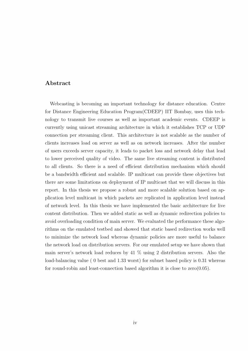
Abstract
Webcasting is becoming an important technology for distance education. Centre
for Distance Engineering Education Program(CDEEP) IIT Bombay, uses this tech-
nology to transmit live courses as well as important academic events. CDEEP is
currently using unicast streaming architecture in which it establishes TCP or UDP
connection per streaming client. This architecture is not scalable as the number of
clients increases load on server as well as on network increases. After the number
of users exceeds server capacity, it leads to packet loss and network delay that lead
to lower perceived quality of video. The same live streaming content is distributed
to all clients. So there is a need of efficient distribution mechanism which should
be a bandwidth efficient and scalable. IP multicast can provide these objectives but
there are some limitations on deployment of IP multicast that we will discuss in this
report. In this thesis we propose a robust and more scalable solution based on ap-
plication level multicast in which packets are replicated in application level instead
of network level. In this thesis we have implemented the basic architecture for live
content distribution. Then we added static as well as dynamic redirection policies to
avoid overloading condition of main server. We evaluated the performance these algo-
rithms on the emulated testbed and showed that static based redirection works well
to minimize the network load whereas dynamic policies are more useful to balance
the network load on distribution servers. For our emulated setup we have shown that
main server’s network load reduces by 41 % using 2 distribution servers. Also the
load-balancing value ( 0 best and 1.33 worst) for subnet based policy is 0.31 whereas
for round-robin and least-connection based algorithm it is close to zero(0.05).
iv

Acknowledgements
I express my sincere gratitude towards my advisor Prof. Purushottam Kulka-
rni and co-advisor Prof. Sridhar Iyer for their constant support, encouragement
and inspiration throughout the project. I also thank Mr. Rahul Deshmukh, Web
and technical coordinator Of CDEEP, for his valuable support in helping me under-
stand the CDEEP Webcast network setup and the problem definition. I also want to
thank my lab-mates for their help during this course.
Harshad Inarkar.
IIT Bombay,
June, 2010.
v
Contents
Abstract iv
Acknowledgements v
1 Introduction 1
1.1 CDEEP Webcast . . . . . . . . . . . . . . . . . . . . . . . . . . . . . 1
1.2 Requirement For Live Webcast . . . . . . . . . . . . . . . . . . . . . 2
1.3 Problem Definition . . . . . . . . . . . . . . . . . . . . . . . . . . . . 2
1.4 Organization Of Report . . . . . . . . . . . . . . . . . . . . . . . . . 3
2 Related Work 4
2.1 Video Streaming Key Terms . . . . . . . . . . . . . . . . . . . . . . . 4
2.2 Transcoding and Adaptive bit-rate configuration . . . . . . . . . . . . 7
2.3 Multicast Based Mechanisms . . . . . . . . . . . . . . . . . . . . . . . 7
2.3.1 IP Multicast . . . . . . . . . . . . . . . . . . . . . . . . . . . . 7
2.3.2 Application Level Multicast . . . . . . . . . . . . . . . . . . . 8
2.4 Peer-to-Peer (P2P) Streaming . . . . . . . . . . . . . . . . . . . . . . 9
2.4.1 P2P Systems . . . . . . . . . . . . . . . . . . . . . . . . . . . 9
2.4.2 P2P Live Streaming . . . . . . . . . . . . . . . . . . . . . . . 10
2.5 Content Distribution Based Streaming . . . . . . . . . . . . . . . . . 11
3 Campus Network Architecture 12
3.1 IIT Bombay Network Architecture . . . . . . . . . . . . . . . . . . . 12
3.2 CDEEP Live Video Transmission Network Architecture . . . . . . . . 13
4 Functional Model Of Content Distribution Architecture 16
4.1 System Architecture . . . . . . . . . . . . . . . . . . . . . . . . . . . 16
4.2 Implementation . . . . . . . . . . . . . . . . . . . . . . . . . . . . . . 18
vi
5 Experimental Evaluation 19
5.1 Low Scale Webcasting Experiment . . . . . . . . . . . . . . . . . . . 19
5.1.1 Experimental Setup . . . . . . . . . . . . . . . . . . . . . . . . 19
5.1.2 Experimental Methodology . . . . . . . . . . . . . . . . . . . . 20
5.1.3 Performance Evaluation . . . . . . . . . . . . . . . . . . . . . 21
5.2 Scaled Up Webcasting Experiment . . . . . . . . . . . . . . . . . . . 25
5.2.1 Experimental Setup . . . . . . . . . . . . . . . . . . . . . . . . 25
5.2.2 Experimental Methodology . . . . . . . . . . . . . . . . . . . . 27
5.2.3 Performance Evaluation . . . . . . . . . . . . . . . . . . . . . 28
6 Conclusions And Future Work 33
6.1 Conclusions . . . . . . . . . . . . . . . . . . . . . . . . . . . . . . . . 33
6.2 Future Work . . . . . . . . . . . . . . . . . . . . . . . . . . . . . . . . 33
Bibliography 34
vii

List of Figures
2.1 Effect Of Play Out Buffer [19] . . . . . . . . . . . . . . . . . . . . . . 6
2.2 IP Multicast . . . . . . . . . . . . . . . . . . . . . . . . . . . . . . . . 7
2.3 Application Level Multicast . . . . . . . . . . . . . . . . . . . . . . . 8
3.1 IITB Network Layout [1] . . . . . . . . . . . . . . . . . . . . . . . . . 12
3.2 Part Of IITB Network Physical Diagram. . . . . . . . . . . . . . . . . 13
3.3 Architecture of the CDEEP Webcast. . . . . . . . . . . . . . . . . . . 14
4.1 Proposed Architecture . . . . . . . . . . . . . . . . . . . . . . . . . . 17
5.1 Testbed for Low scale Streaming Experiment . . . . . . . . . . . . . . 20
5.2 Comparison Of Unicast and Multicast Server I/O rate . . . . . . . . . 21
5.3 Comparison Of Unicast and Multicast Server CPU Utilization . . . . 22
5.4 Distribution Server CPU and Network Utilization . . . . . . . . . . . 22
5.5 Comparison Of Unicast and Multicast Client Average Frame Delay . 23
5.6 Comparison Of Unicast and Multicast Client Average Frame Jitter . 23
5.7 Comparison Of Unicast and Multicast Clients Average mean packet delay 24
5.8 Comparison Of Unicast and Multicast Client Average packet jitter . . 24
5.9 Logical Unicast Architecture . . . . . . . . . . . . . . . . . . . . . . . 25
5.10 Logical Content Distribution Architecture . . . . . . . . . . . . . . . 26
5.11 Physical Experiment Setup . . . . . . . . . . . . . . . . . . . . . . . . 27
5.12 CPU Utilization of Client Machine . . . . . . . . . . . . . . . . . . . 27
5.13 CPU Utilization of Main Streaming Server . . . . . . . . . . . . . . . 28
5.14 Comparison of clients avg-packet-delay for Unicast architecture and
CDN Subnet based redirection algorithm . . . . . . . . . . . . . . . . 29
5.15 Comparison Of Average Frame rate and Average frame drop . . . . . 29
5.16 Comparison Of I/O rate in GW1 and GW2 . . . . . . . . . . . . . . 31
5.17 I/O rate of Main Streaming Server and CDN Server1 . . . . . . . . . 31
5.18 Network Utilization Balancing ratio for redirection algorithms . . . . 32
viii

Chapter 1
Introduction
Distributing live content (webcasting) is becoming more popular worldwide. We-
bcasting of live events such as music concerts and sports events e.g live cricket or
football matches is most commonly used. Typically, a central server handles stream-
ing services, is responsible for servicing all client requests. We term this as Unicast
Streaming Mechanism, where streaming capability is available only at the source. In a
large-scale network with a large number of concurrent client requests, streaming from
only one source has been proven to be inefficient because of the limitation of stream-
ing server capacity and link bandwidth constraints in the network [21]. As the live
content to be distributed remains same, to improve the performance of live webcast
in terms of serving more clients with the required quality, multicasting mechanisms
can be used. Other techniques are transcoding video of high bit rate to low bitrate or
some other video format[16]. But transcoding leads to compromising of video qual-
ity. Content replication also known as Content Delivery Network technology,[20] is
a robust way to increase the number of serviced clients, reduce network traffic and
workload at central server. We will discuss this technology in detail in next chapter.
1.1 CDEEP Webcast
E-learning System or distance education program started using this technology to
broadcast live video courses and spread knowledge across the world. Centre for Dis-
tance Engineering Education Program(CDEEP)[4] was established in IIT Bombay
to make its own courses available to large number of students in India as well as
in abroad. Apart from regular courses CDEEP webcasts main events such as Con-
vocation Day in which VIP guests give talk. Viewership of such events depends on
marketing or publicity strategy, VIP guests reputation and also the perceived qual-
ity of streaming video. The highest number of users subscribing for the webcast
was 9000+ for a talk in Oct 2007 by Sunita Williams as said by CDEEP coordi-
nator Mr. Rahul Deshmukh. Currently, CDEEP streams live content with a bit1

CHAPTER 1. INTRODUCTION 2
rate of 100 Kbps. They arrived to this number taking into account poor net con-
nection at some of the end users. Clearly to serve large number of users with lim-
ited bandwidth available is a challenging task for CDEEP. In the following section
we will discuss the client side as well as server side requirements for live stream-
ing.
1.2 Requirement For Live Webcast
Digital video consists of frames which have to be displayed at a constant rate for live
streaming of video. So Webcasting has a real time constraint which has to be met for
better perceived quality of video. Current architecture of Webcasting uses unicast
live streaming in local network. Due to unicast streaming number of streams output
from the streaming server is same as the number of streaming clients. As the number
of streaming clients increases load on the server as well as on network increases. This
incurs network delay, packet loss, frame loss and delay. So the real-time constraint
of video streaming application will not be met, hence perceived quality of video will
decrease.
On the other hand local network users (IIT B Campus) can expect good quality
of video in terms of bitrate, resolution and frame rate of video. Currently CDEEP
webcasts using 100 kbps in both local as well as outside world. CDEEP wants to
deliver the content to maximum possible users anywhere in the world including peo-
ple having limited bandwidth connection also can watch the live content. But If
CDEEP increases the encoding bitrate (e.g. 800 kbps) to give better quality of video
to campus users,that will lead to higher demand on streaming server as well as on
IIT-B network. So clearly there is a need to change the Webcasting architecture for
better scalability (in terms of number of concurrent users) along with better quality
of video.
1.3 Problem Definition
We need to develop webcasting architecture for CDEEP such that it is more scalable
(concurrent users) ensuring lower demand on the server and network. Also CDEEP
webcasting should provide video with its required quality of service and real-time
constraints.

CHAPTER 1. INTRODUCTION 3
After building required architecture we have to evaluate the performance of the sys-
tem in terms of perceived video quality. Then for the implemented architecture we
need to evaluate the performance for different parameters of the system to select the
best of it. For evaluation purpose we need to use testbed which should be maximum
approximated with current IIT, Bombay and CDEEP structure. Then we can deploy
this architecture physically on CDEEP and use it for future live webcast events.
1.4 Organization Of Report
The organization of the thesis is as follows.Chapter 2 presents the literature survey in
the area of live streaming and the mechanisms to improve performance of the stream-
ing. We present IIT B and CDEEP infrastructure in chapter 3. Also chapter 4 and
5 presents the functional overview of the proposed content distribution architecture
and its implementation. Then in chapter 6 performance evaluation of proposed archi-
tecture using two testbeds is discussed. And we conclude the thesis with the future
work in chapter 7.

Chapter 2
Related Work
In this section we will discuss the live video streaming parameters and key terms[19].
Then discussion for related multicasting techniques for scalable live webcast will be
done.
2.1 Video Streaming Key Terms
In this section we will get acquainted with some of the key terminologies of live video
distribution techniques.
• Transcoding:
A transcoder converts existing video stream into a new stream with a different for-
mat or encoding rate. As discussed in [19],the important transcoding options are
changing frame rate, encoding bit rate, streaming protocol, compression technique.
A simple approach for encoding is to decompress the video stream, process it and
then recompress. This process also known as spatial domain processing in which
decoded (Original) samples are used for compression. Two major disadvantages of
this process are
– Media decoding and then encoding is CPU extensive and hence efficiency is
relatively lower.
– Generally produces lower quality than if the media was coded directly from the
original source to the same bitrate
Relatively fast transcoding can be achieved by directly manipulating the com-
pressed data in the frequency domain.That is the above process can be made less
CPU extensive by selectively re-use compression decisions already made in the
compressed media. This process is also known as compressed-domain transcod-
ing.
4

CHAPTER 2. RELATED WORK 5
• Streaming Protocols:
Selection of transport protocols based on UDP or TCP makes an impact on stream-
ing performance. Here we will discuss some standard video streaming protocols.
1. HTTP Streaming: HTTP [10] is a connection-oriented protocol that uses
TCP as a transport protocol. This is a modified version of traditional stateless
HTTP protocol. Web server does not terminate the response to the client af-
ter data has been served. An HTTP stream has the advantages of bypassing
the Proxy of firewall restrictions. This makes it very popular in the Inter-
net.
2. MMS - Microsoft Media Services: MMS [9] is Microsoft’s proprietary
streaming protocol used for transferring real time Multimedia data (audio/video).
Client initiates the session with the MMS streaming server using TCP connec-
tion. Streaming video can be transported via UDP or TCP (MMSU and MMST
protocols). It uses a Fallback Protocol approach. If the client cannot negotiate
a good connection using MMS over UDP, it will try for MMS over TCP. If that
fails, the connection can be made using a modified version of HTTP (always
over TCP). This is not as ideal for streaming as in MMS over UDP, but ensures
connectivity. The default port for MMS is 1755.
3. RTP Real-Time Transport Protocol: RTP [12] is used for streaming me-
dia, video teleconference application. RTP mostly works on top of UDP. RTP
is usually collaborated with RTP Control Protocol (RTCP). RTP carries the
multimedia data and RTCP is used for monitoring transmission statistics and
QoS information.
• Playout Buffer:
It is common for streaming media clients to have a 5 to 15 second buffering before
playback starts [19].Important advantages of play out buffering are:
– Jitter reduction: Variations in network conditions cause the time it takes
for packets to travel between identical end-hosts (packet delay)to vary. Such
variations can be due to a number of possible causes, including queuing delays,
congestion, network overload, link-level retransmissions. Jitter causes jerkiness

CHAPTER 2. RELATED WORK 6
in playback due to the failure of some frames (group of packets) meet their
real-time presentation deadlines, so that they are delayed or skipped. The use
of buffering effectively extends the presentation deadlines for all media samples,
and in most cases, practically eliminates playback jerkiness due to delay jitter.
The advantages of a playback buffer are illustrated in Figure 2.1. Packets are
transmitted and played at a constant rate, and the playback buffer reduces the
number of late packets which are delayed or skipped.
– Error recovery through retransmissions: The extended presentation dead-
lines for the media samples allow retransmission to take place when packets are
lost. e.g., when UDP is used in place of TCP for transport. Since compressed
media streams are often sensitive to errors,the ability to recover losses greatly
improves streaming media quality.
Figure 2.1: Effect Of Play Out Buffer [19]
– Smoothing throughput fluctuation: Since time varying channel gives rise
to time varying throughput, the buffer can provide the streaming live content
to sustain when throughput is low. This is required as there is no guarantee
that server will reduce its encoding rate based on the drop in the channel.
Some disadvantages of buffering can be storage requirements at the streaming
client, buffering also introduces additional delay before playback can begin or re-
sume.

CHAPTER 2. RELATED WORK 7
2.2 Transcoding and Adaptive bit-rate configuration
In this [16] paper, web content-adaptation to improve server overload performance
is discussed. We can apply this technique to webcast architecture in which multiple
instances of live streaming can be kept on a server. This multiple instances are of
variable bitrate and video quality. As the server overload condition arise clients can
be redirected to transcoded stream which have lower configured video quality. But
in this architecture we have to compromise the quality of video.
2.3 Multicast Based Mechanisms
Unicasting these live contents to large number of users is not a feasible option as
it requires high demand on server as well as network and therefore some form of
multicasting has to be employed. We will discuss multicasting mechanisms.
2.3.1 IP Multicast
IP Multicast (network level multicast)allows a single packet transmitted at the source
to be delivered to multiple receivers [17]. This is achieved by replicating the packet
within the network at routers using a distribution Multicast tree rooted at the
source . These routers are specialized to support multicast IP addresses (224.0.0.0-
239.255.255.255) and store the multicast group information or state.
Figure 2.2: IP Multicast
As shown in Figure 2.2, link costs are shown besides each link, [17]. R1 and R2
are multicast routers. Node A is a source and node B, C, D are recipients. Multi-
cast tree is constructed using DVMRP (Distance Vector Multicast Routing Protocol).
DVMRP [18] is multicast protocol in which distribution tree is formed using shortest

CHAPTER 2. RELATED WORK 8
path between sender and recipient. Node A sends a packet to R1. This Multicast
router duplicates the packet and sends it to R2 and B. R2 again distributes packets
to Node C and D.
Though the IP multicast is deployable in Local network it has some drawbacks.Router
need to store per group state so that it increases the complexity and scaling problem.
It lacks management of providing multicast IP addresses to a group. In current IP
multicast model any arbitrary source can send data to any arbitrary multicast group
which leads to security problem. IP multicast is a best effort service which ignores
the QoS support. Hence, it is not deployed widely.
2.3.2 Application Level Multicast
Due to the problems involved in deploying IP multicast, application-level multicast
(ALM) has gained popularity. In this approach [21], the upstream capacity of receiv-
ing clients is used for distribution of live content. Here packet duplication is done in
(end user) application level instead of (router) IP level. As shown in the Figure 2.3
multicast overlay tree is formed with source S as a root and this tree spans all the
receivers. A subset of the nodes receive the content directly from the source and the
others obtain it from the receivers in the level above them. This reduces the load on
the source, as it doesnt have to stream the content to all the receivers.
Figure 2.3: Application Level Multicast
There are basically two methods for construction of distribution tree. First is a
tree based that is members explicitly select their parents from among the members
they know, e.g. Application Layer Multicast Architecture ALMA [21]. This method
CHAPTER 2. RELATED WORK 9
is simple and efficient to use but this tree building process must prevent the loop in
a tree also has to handle partition created by node failures. Second method as in
NARADA[21], is to build a Mesh that is rich connected graph of nodes with some de-
sirable performance properties, Then it constructs shortest path spanning tree rooted
at the corresponding source.
Application layer multicast looks very complex in implementing and other drawback
is it needs extra bandwidth from clients (peers) and dependent on them. The high dy-
namism of clients connection and disconnection makes the mesh or tree maintenance
more complex.
2.4 Peer-to-Peer (P2P) Streaming
An increasingly popular alternative consists of using the often idle capacity of the
clients to share the distribution of the video with the servers, through the present
mature Peer to Peer (P2P) systems, which are virtual networks developed at the
application level over the Internet infrastructure. The nodes in the network, called
peers, peer their resources (bandwidth, processing power, storing capacity) to the
other nodes, basically because they all share common interests (through the consid-
ered application). In this section we discuss some P2P based live streaming systems
and before that the popular file sharing P2P systems are discussed.
2.4.1 P2P Systems
P2P networks are becoming more and more popular today.P2P systems are mostly
used for file sharing and file distribution, for example, BitTorrent[3],DC++ (Direct
Connect Client)[6], etc. In BitTorrent, a list of the peers currently downloading each
file is maintained by a central Web server (called the tracker). Using this list, each peer
knows, at any time, a subset of other peers that are downloading the same file. The file
is divided into number of pieces (called chunks). Every peer knows which chunks are
owned by the peers in its swarm, and explicitly pulls the chunks that it requires. Peers
request the chunks which fewest number of peers have (rarest-first download policy),
and peers upload chunks first to the peer requesters that are uploading data to them
at the fastest rate (tit-for-tat upload policy).This kind of protocols cannot be used di-
rectly for live video distribution, because the first chunks of the file are not downloaded
first, and therefore the file cannot be played until the download has been completed.

CHAPTER 2. RELATED WORK 10
2.4.2 P2P Live Streaming
P2P live streaming have to satisfy harder real-time constraints unlike file sharing
applications. The other difficulty is dynamic and unpredictable property of nodes
joining and leaving the networks.Nowadays some commercial P2P networks for live
video distribution are available.The most successful are PPlive with more than 200000
concurrent users on a single channel (reaching an aggregate bit-rate of 100 Gbps),
SopCast with more than 100000 concur- rent users reported by its developers, Cool-
Streaming with more than 25000 concurrent users on a single channel. Freecast,distruStream,Peercast,GoalBit
are some examples of opensource systems. We discuss some of them here.
1. PPLive: PPLive [11] is the most popular P2PTV software, especially for Asian
users. Born as a student project in the Huazhong University of Science and Tech-
nology of China, PPLive uses BitTorrent-like protocol, with a channel selection
bootstrap from a Web tracker, and peer transfers (download/upload) video in
chunks from/to multiple peers. The distribution engine (BitTorrent-like protocol)
does not use the rarest-first download policy, because the streaming must satisfy
real-time constraints. Also the tit- for-tat upload policy is not applied, when a
client joins a channel, the other peers in the network send chunks forcefully to
minimize the playback startup delay.
2. SopCast: SopCast [13], created at the Fudan University of China, is very simi-
lar to the PPLive project. It uses a bittorrent-like approach, with a proprietary
protocol very close to the PPLive protocol.
3. CoolStreaming: CoolStreaming [5] (also known as DONet) is the prede- cessor
of PPLive and SopCast, now forced to close down due to copyright issues. Also
using a proprietary protocol, and closed source-code.A difference of CoolStream-
ing, with respect to PPLive and SopCast, is that the video stream is decomposed
into six sub-streams by a rotating selection of video chunks.
4. Goalbit: Goalbit [8] is the first open source P2P system for the live webcast
through the Internet.GoalBit is a free software project for video and audio stream-
ing. It is released under the GNU General Public License.GoalBit uses BitTorrent
streaming.
The streaming encapsulation, defined as GoalBit Packetized Stream (GBPS), takes
the muxed stream and generates fixed size pieces (chunks), which are later dis-
tributed using the Goal- Bit Transport Protocol (GBTP bittorrent-like approach).
Finally the GoalBit player reproduces the video streaming consuming the pieces
CHAPTER 2. RELATED WORK 11
obtained through GBTP.
2.5 Content Distribution Based Streaming
Content Distribution Networks for video broadcast services are vastly deployed where
a set of servers (located at strategic points around the Internet) cooperates transpar-
ently to deliver content to end users. In the Internet context this type of service is
provided by private organizations such as Akamai [2]. In this scheme clients try to
connect to a streaming server which redirects them to a best server which supposed
to give a better video quality performance.
This architecture internally use redirection algorithms to load balance the cluster of
servers as well as for finding best server for the clients. The algorithms can be round
robin, least-CPU or least-network-connection based.
The P2P based systems looks better than above cluster-based load balancing in terms
of scalability but content distribution has advantage of being more robust. The highly
dynamic behavior of clients joining and leaving the system can cause degradation of
quality of video in terms of delay and buffering.

Chapter 3
Campus Network Architecture
3.1 IIT Bombay Network Architecture
IIT Bombay campus Network is basically divided into 3 parts.
• Academic Area: This includes Convocation, Main Building ,all the Departments
including CDEEP. The Heart of the IIT Bombay network is in Kresit Department
called as Computer Center. Which provides the network bandwidth to all the users
in the campus. There are many fiber outgoing links from CC to various department
of IIT Bombay.
Figure 3.1: IITB Network Layout [1]
12

CHAPTER 3. CAMPUS NETWORK ARCHITECTURE 13
• Hostels: As shown in Figure 3.1 Hostel 1 to 5 are situated to the right side of the
Computer Center(Kresit) And other remaining hostels to the left. As Figure3.2
shows Hostel-8 Extreme router(H8-Extreme) is connected to CC-Extreme via fiber
links. Gateways of H11,H8,H9,H7,H6,H12 are connected to H8-Extreme. Also the
Gateways of H1 to H5 are connected to H3-Extreme router which is connected to
CSE-Extreme router.
Figure 3.2: Part Of IITB Network Physical Diagram.
• Residential Area: This Consists of residential locality in which teaching and
non-teaching staffs reside. Gateways of these areas are connected to ghar-resnet
switch which is connected to CC-Extreme.
3.2 CDEEP Live Video Transmission Network Architecture
Currently CDEEP uses following methods for live transmission of regular courses.
• Satellite Technology IIT Bombay signed up with the Indian Space Research Or-
ganization (ISRO) from Jan 2008. Live and interactive courses are transmitted
through the EDUSAT satellite. EDUSAT is the first Indian satellite built mainly
intended to serve educational sector. ISRO provides its bandwidth free and IIT

CHAPTER 3. CAMPUS NETWORK ARCHITECTURE 14
Bombay distributes its content free. For receiving the video transmission satellite
requires Student Interactive Terminal (SIT) to be installed at the remote cen-
ters.
• Video Conference(VC) As the installing SIT takes time and cost, video conference
is an alternative to transmission through satellite. Main concern in this technology
is an availability of bandwidth to support high quality of video. Currently 2 Mbps
bandwidth is used for VC.
• Webcasting Technology IIT Bombay started exploring this technology from Jan-
uary 2008. Webcasting is used for distributing live courses or events. Webcasting
uses separate streams for Internet and intranet (local IIT Bombay network). We
will explain this in more detail.
Figure 3.3: Architecture of the CDEEP Webcast.
In Figure 3.3 the live video content is captured by Video recorder or Camera.
This act as a video source which is encoded that is converted into smaller form (known
as compression of video). The encoding technique is most important as it reduces the
actual size of the video to be transmitted over the network.
CDEEP Webcast server uses different video streams for Internet and Intranet (local
network). In local network, webcast server itself handles all the streaming clients
requests. It creates a different TCP or UDP connection for each local client (known
as Unicast streaming).

CHAPTER 3. CAMPUS NETWORK ARCHITECTURE 15
IIT Bombay Computer Center (CC) provides 2 Mbps pipe dedicated for CDEEP Web-
cast services. As this available Internet bandwidth is too limited to handle large num-
ber of streaming clients outside of the IIT Bombay campus (remote clients), CDEEP
hires a company such as Akamai Technologies[2] which provides a distributed comput-
ing platform which can handle large number of clients requests outside of the campus.

Chapter 4
Functional Model Of Content Distribution Architecture
We discussed the two types of multicast mechanisms. As IP multicast has some
limitations in deploying we will think of applying application level multicast to our
CDEEP Webcasting server. First we start with the basic algorithm with one level
of application level multicast. This algorithm propose the following architecture for
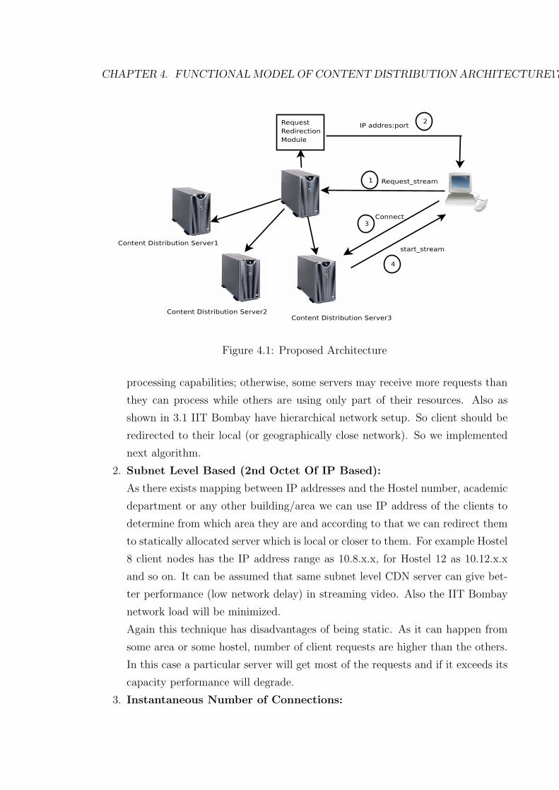
CDEEP webcasting as shown in Figure 4.1.
4.1 System Architecture
• Streaming Server:
This is the main server which encodes video from Camera and starts live streaming
of a regular course or event.
• Content delivery server:
These are content delivery servers which get the direct video stream from streaming
server.Regular streaming clients get connected to one of these content distribution
servers and get the live stream.
• Request Redirection Module:
This is the most important module in which clients streaming requests are redi-
rected to content delivery server depending on the specified redirection policy.This
system use different algorithms to control traffic. The goal of these algorithms is
to intelligently distribute load and/or maximize the utilization of all servers within
the cluster. Some examples of these algorithms include:
1. Round Robin:
Client requests are redirected to one of the content delivery server in round robin
fashion. A round-robin algorithm distributes the load equally to each server, re-
gardless of the current number of connections or the response time or any other
parameter. Round-robin is suitable when the servers in the cluster have equal
16
CHAPTER 4. FUNCTIONAL MODEL OF CONTENT DISTRIBUTION ARCHITECTURE17
Figure 4.1: Proposed Architecture
processing capabilities; otherwise, some servers may receive more requests than
they can process while others are using only part of their resources. Also as
shown in 3.1 IIT Bombay have hierarchical network setup. So client should be
redirected to their local (or geographically close network). So we implemented
next algorithm.
2. Subnet Level Based (2nd Octet Of IP Based):
As there exists mapping between IP addresses and the Hostel number, academic
department or any other building/area we can use IP address of the clients to
determine from which area they are and according to that we can redirect them
to statically allocated server which is local or closer to them. For example Hostel
8 client nodes has the IP address range as 10.8.x.x, for Hostel 12 as 10.12.x.x
and so on. It can be assumed that same subnet level CDN server can give bet-
ter performance (low network delay) in streaming video. Also the IIT Bombay
network load will be minimized.
Again this technique has disadvantages of being static. As it can happen from
some area or some hostel, number of client requests are higher than the others.
In this case a particular server will get most of the requests and if it exceeds its
capacity performance will degrade.
3. Instantaneous Number of Connections:

CHAPTER 4. FUNCTIONAL MODEL OF CONTENT DISTRIBUTION ARCHITECTURE18
A least-connection algorithm sends requests to servers in a cluster, based on
which server is currently serving the fewest connections. This algorithm will not
guarantee the local users will be connecting to local server. Still it will maintain
the load balancing at all the servers.
4. Dynamic Network Utilization Based:
Clients are redirected to a server whose network utilization is least among all
servers. It may happen that some servers are running some other applications
(or multiple streaming) so only number of connections parameter wont be useful
for redirecting and load balancing. Their actual network utilization parameter
should be used for fair load balancing.
For network utilization we are using bwm-ng, bandwidth monitor software through
which we get 3 sec average of content delivery server’s network utilization and
we continuously send this average value to main server in 3 sec time interval.
If the load on the system are highly dynamic then we can reduce the update
interval for better load balancing on the servers.
4.2 Implementation
To test the proposed solution simple client and server socket programming code in
C++ is written.
• Server:
This is executed on main Streaming server. It listens on TCP port 30000 and ac-
cept incoming streaming client requests using VLC player. It uses HTTP streaming
protocol. It also contains the Request Redirection module which contains all the
algorithm discussed above. Round robin, least-connection based and subnet-based
redirection are done by maintaining information of all the distribution servers.
Information contains IP address, instantaneous number of connections and instan-
taneous network utilization.
• Content Delivery Server:
This is executed on distribution server machine which will receive live stream di-
rectly from main server and itself start streaming to other clients. This special
clients can be added or disconnected dynamically.
• Regular Client:
Client machine send request to main server and is redirected to one of the special
clients to receive live streaming. It uses mplayer client to get the live stream from
the server.

Chapter 5
Experimental Evaluation
We will divide our set of experiments into Low scale webcasting and Scaled up We-
bcasting. As we will explain later one is more relevant to IIT Bombay network.
5.1 Low Scale Webcasting Experiment
5.1.1 Experimental Setup
The objective of the experiment is to show the impact on the quality of video per-
ceived by clients caused by using unicasting architecture for live webcast. Also this
experiment will validate our approach of CDN architecture in which we show the
improvement over the Unicasting architecture.
• Testbed: As shown in Figure 5.1, in this experiment we simulate the CDEEP
webcasting. We use one laptop (Linux platform) act as a streaming server and
three desktop machines (one Windows platform and other two Linux platform)
who receive the video stream from main streaming server. Software running on the
Streaming Server is VLC Player [14]. VLC player encodes a stored video file (video
clip) using H.264 video codec with 800 Kbps and audio codec as MPGA, 128 Kbps
with frame rate as 25 fps. It streams the video using HTTP streaming protocol.
Clients receive this live stream using VLC player with using play-out delay as 300
ms to mitigate the jitter effect. As for this experiment number of clients are less
we are using 10 Mbps Ethernet card for streaming server to show the overloading
effect more correctly.
• Performance Metrics:
– Video Frames Inter arrival Delay and Packet Inter arrival delay : This is a time
delay between two consecutive arrivals of frames and packets.
– Packet Delay/Packet Jitter It is the variance of the inter-packet or inter
frame time. The delay of frames and the variation of the delay, usually referred19

CHAPTER 5. EXPERIMENTAL EVALUATION 20
(a) Unicast Streaming Testbed1 (b) Multicast With 1 CDN Server Testbed1
Figure 5.1: Testbed for Low scale Streaming Experiment
to as frame jitter are most commonly used.
• Performance Measurement Tools and Methods: To measure the each video
frames timestamp and frame rate we are using FRAPS [7]. It is a real time capture
and benchmarking tool (works in Windows platform).One Windows desktop ma-
chine runs this application after starting the streaming and stores the frame rate
and frame times in respective files.
We use Wireshark (Network Analyzer)[15] to analyze the I/O rate as well as packet
statistics. For measuring CPU utilization in streaming server we used script using
Linux top command.
5.1.2 Experimental Methodology
• Unicast streaming experiment: For this experiment as shown in Figure 5.1(a)
laptop act as a streaming server. Desktop-1 (windows platform) starts only 1
streaming client and desktop-2 and desktop-3 starts multiple clients to connect to
streaming server. We increase the number of clients in each machine as 1,3,4,5.
So effectively total number of clients connecting a streaming server increases as
1,3,7,9,11. For each experiment we are streaming the video clip for 300 sec. The
performance of this system is evaluated in the next subsection.
• Multicast streaming experiment: In this experiment we use one content deliv-
ery server. For this experiment Subnet-level (3rd octet of IP address) redirection
policy is used. So while doing experiments desktop-1 and desktop-2 get connected
CHAPTER 5. EXPERIMENTAL EVALUATION 21
to laptop (main streaming server) and desktop-3 get connected to content delivery
server. We will evaluate this architecture in next subsection.
5.1.3 Performance Evaluation
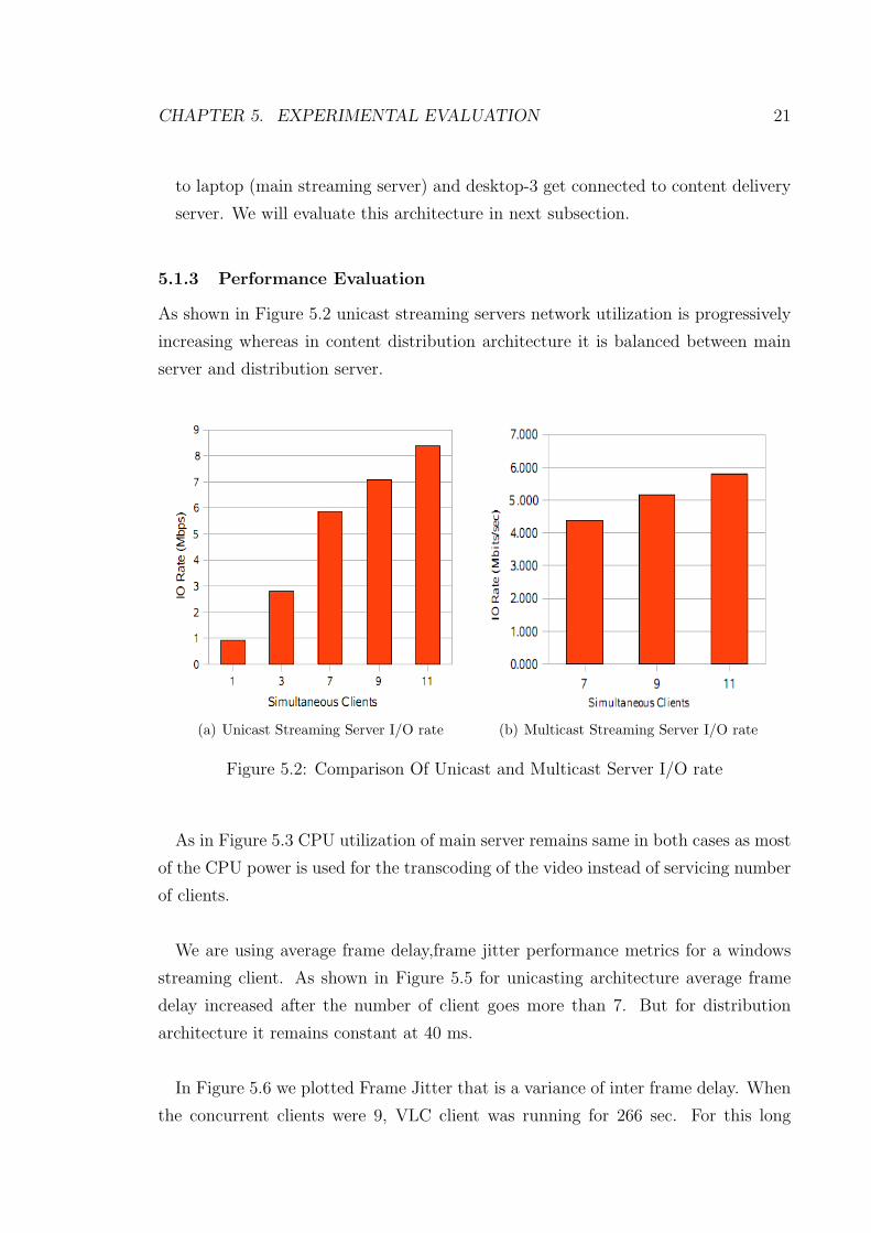
As shown in Figure 5.2 unicast streaming servers network utilization is progressively
increasing whereas in content distribution architecture it is balanced between main
server and distribution server.
(a) Unicast Streaming Server I/O rate (b) Multicast Streaming Server I/O rate
Figure 5.2: Comparison Of Unicast and Multicast Server I/O rate
As in Figure 5.3 CPU utilization of main server remains same in both cases as most
of the CPU power is used for the transcoding of the video instead of servicing number
of clients.
We are using average frame delay,frame jitter performance metrics for a windows
streaming client. As shown in Figure 5.5 for unicasting architecture average frame
delay increased after the number of client goes more than 7. But for distribution
architecture it remains constant at 40 ms.
In Figure 5.6 we plotted Frame Jitter that is a variance of inter frame delay. When
the concurrent clients were 9, VLC client was running for 266 sec. For this long

CHAPTER 5. EXPERIMENTAL EVALUATION 22
(a) Unicast Streaming Server CPU utilization (b) Multicast Streaming Server CPU utilization
Figure 5.3: Comparison Of Unicast and Multicast Server CPU Utilization
(a) Distribution Server CPU Utilization (b) CDN Server Network Utilization
Figure 5.4: Distribution Server CPU and Network Utilization
time we had greater variation in inter frame delay. Whereas when concurrent clients
were 11 at that time VLC was running for 53 sec hence fewer frames have arrived
so calculated jitter is less than that of with 11 concurrent clients. For distributed
architecture frame jitter is negligible.

CHAPTER 5. EXPERIMENTAL EVALUATION 23
(a) Unicast Streaming Client Average FrameDelay
(b) Multicast Streaming Client Average FrameDelay
Figure 5.5: Comparison Of Unicast and Multicast Client Average Frame Delay
(a) Unicast Streaming Client Average FrameJitter
(b) Multicast Streaming Client Average FrameJitter
Figure 5.6: Comparison Of Unicast and Multicast Client Average Frame Jitter
In Figure 5.7 we plotted average (with respect to number of clients) of mean aver-
age packet delay, mean packet jitter. As the concurrent users are increasing packet
delay is increasing. When the concurrent clients were 11 the variation in inter frame
delay is very high. For proposed architecture it is not changing much even if number

CHAPTER 5. EXPERIMENTAL EVALUATION 24
(a) Unicast Streaming Clients average meanpacket delay
(b) Multicast Streaming Clients Average meanpacket delay
Figure 5.7: Comparison Of Unicast and Multicast Clients Average mean packet delay
of clients increases.
(a) Unicast Streaming Client Average packetjitter
(b) Multicast Streaming Client Average packetjitter
Figure 5.8: Comparison Of Unicast and Multicast Client Average packet jitter
As in Figure 5.8, packet jitter for unicast in highest for 11 simultaneous clients. For
proposed architecture of content distribution it is almost steady even if simultaneous

CHAPTER 5. EXPERIMENTAL EVALUATION 25
clients increases.
5.2 Scaled Up Webcasting Experiment
We need to scale up the streaming experiment to emulate the IIT Bombay network.
Unlike the previous experiments this experiment is done in isolated way. That is the
testbed should not be connected to campus network. Also for the better approxima-
tion of IIT Bombay network setup we will emulate 3 subnetworks as in Kresit/CC,
Hostel 8, and CSE-dept. We will explain the physical as well as logical setup in
following section. In this experiment we will evaluate the performance of different
algorithms discussed earlier.
5.2.1 Experimental Setup
GW1 GW2 GW3sw
sw
sw
Streaming Mplayer_Clients 10.1.0.X
Streaming Mplayer_Clients 10.2.0.X
Streaming Mplayer_Clients 10.3.0.X
10.1.0.1 10.2.0.1 10.3.0.1
Hostel_Gateway Kresit_Gateway CSE_Gateway
Streaming VLC_Main_Server
Figure 5.9: Logical Unicast Architecture
To approximate the campus network we will try to emulate the part of campus
section as shown in Figure 3.2. We choose this section with the assumption of
expected number of viewers of live webcast are more as compared to rest of the
campus. In Figure 3.2, CDEEP webcasts live content from Kresit/CC network.
So hostels 6 to 13 get the live stream via H8-Extreme router. And hostels 1 to
5 are connected through CSE-Extreme router. The logical setup of this section
of network is shown in Figure 5.9. In this GW1, GW2, GW3 are the gateway

CHAPTER 5. EXPERIMENTAL EVALUATION 26
router which corresponds to H8-Extreme, CC-Extreme and CSE-Extreme respec-
tively.
Figure 5.10: Logical Content Distribution Architecture
Figure 5.9 shows the logical unicast streaming architecture. In which Streaming
server is in kresit network. Clients from Kresit, H8-Extreme and CSE-Extreme get
connected to the streaming server. In Figure 5.10 content delivery servers are added to
H8-Extreme and CSE-Extreme network. In this case main streaming server redirects
clients to one of the content delivery server using policies discussed and implemented
above.
• Testbed:
As shown in Figure 5.11 above logical setup is mapped to this physical setup. For
the GW1(H8-extreme) network IP address is 10.1.0.0/16, for GW2 (CC-Extreme)
network IP address is 10.2.0.0/16 and for GW3 (CSE-Extreme) network IP ad-
dress is 10.3.0.0/16 . Nodes on each network are connected to Gw1.GW2 and Gw3
having IP address 10.1.0.1, 10.2.0.1 and 10.3.0.1. GW1-GW2 and GW2-Gw3 are
connected through crossover lan cable.
• Performance Metric:
As in previous experiment we are going to use performance metric as Frame
rate,Frame delay, packet delay, packet jitter. The script is used for getting the

CHAPTER 5. EXPERIMENTAL EVALUATION 27
Figure 5.11: Physical Experiment Setup
statistics for video frames of mplayer. For packet statistics we used tcpdump and
tshark.
5.2.2 Experimental Methodology
We are using VLC player as a streaming server and mplayer as streaming clients.Our
implemented tool is used for the redirection of the clients.
• Prelimenary Experiment:
We need to emulate as many number of clients for the experiment as possible. In
this experiment we need to find out how many mplayer clients we can run on sin-
gle machine. For this experiment we started VLC streaming server in our server
machine and then started executing mplayer clients in a client machine. In Figure
5.12 for 25 clients we get approximately 74% maximum CPU utilization and we
select this value as maximum number of mplayer instances that can be played.
0
20
40
60
80
100
0 5 10 15 20 25 30
CP
U %
Clients
CPU Utilization Of Client machine
Max Min
AVG
Figure 5.12: CPU Utilization of Client Machine

CHAPTER 5. EXPERIMENTAL EVALUATION 28
• Experiments:
In this experiment we need to evaluate the performance of the unicast vs static
and dynamic redirection policies. As shown in Figure 5.11 we are running multiple
mplayer instances (upto 25) in each client machine. Main streaming server is in
network (Kresit or GW2 network). Streaming video specifications are: 1000 Kbps
video bitrate, H.264 video codec and mp3 audio codec with 192 kbps audio bitrate.
After starting the main streaming server we increase the number of mplayer in-
stances in each client as 1,5,10,15,20,25. We have 5 client machine so effectively
total number of clients goes from 5 to 125. We used this input setup for all exper-
iments (Unicast,static redirection and dynamic redirection).
5.2.3 Performance Evaluation
In this section we show the performance analysis of Unicast vs content distribution
using static as well as dynamic redirection policies. First we will show the impact on
client side characteristics and then impact on intermediate routers and then server
side characteristics.
0
20
40
60
80
100
5 25 50 75 100 125
CP
U %
Clients
CPU Utilization
Max AVG
Figure 5.13: CPU Utilization of Main Streaming Server
Figure 5.13 shows there is no change in CPU utilization even with maximum num-
ber of clients (=125). The average CPU utilization is 22 % or 23% whereas maximum
CPU utilization goes upto 40 % utilization and CPU utilization of main streaming
server with increasing number of clients. CPU utilization of main server remains same
in both unicast and content distribution system as most of the CPU power is used
for the transcoding of the video instead of servicing number of clients.
CHAPTER 5. EXPERIMENTAL EVALUATION 29
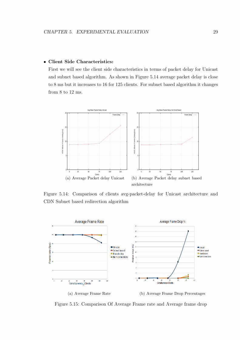
• Client Side Characteristics:
First we will see the client side characteristics in terms of packet delay for Unicast
and subnet based algorithm. As shown in Figure 5.14 average packet delay is close
to 8 ms but it increases to 16 for 125 clients. For subnet based algorithm it changes
from 8 to 12 ms.
0
5
10
15
20
5 25 50 75 100 125
AV
G M
ean F
ram
e D
ela
y(m
s)
Clients
Avg Mean Packet Delay Unicast
Frame Delay
(a) Average Packet delay Unicast
0
5
10
15
20
5 25 50 75 100 125
AV
G M
ean F
ram
e D
ela
y(m
s)
Clients
Avg Mean Packet Delay 2nd Octet Based
Frame Delay
(b) Average Packet delay subnet based
architecture
Figure 5.14: Comparison of clients avg-packet-delay for Unicast architecture and
CDN Subnet based redirection algorithm
(a) Average Frame Rate (b) Average Frame Drop Percentages
Figure 5.15: Comparison Of Average Frame rate and Average frame drop

CHAPTER 5. EXPERIMENTAL EVALUATION 30
Next we plotted combined graphs for all the algorithms. In Figure 5.15 we can
see the client side characteristics in terms of percentage of frame drops and frame
rate. For unicast streaming frame rate is 25 fps till 75 clients. But after that
for 100 and 125 clients it drops to 22 and 20 fps respectively. Frame drop per-
centage for 100 and 125 is 8% and 16%. Whereas for content distribution al-
gorithms frame rate is 25 fps only and frame drop percentage almost negligible.
For all algorithms except the unicast streaming, real time constraints are sat-
isfied. So we need to check other parameters to compare the redirection algo-
rithms.
• Network Side Characteristics:
As shown in Figure 5.16 network load on the intermediate routers are plotted.
Now these graphs signify the load on IIT Bombay network if we use one of these
algorithms. As we can see for subnet based redirection, network load is minimum
(approximately 2 Mbps) as there are only 2 streams going out of Kresit(GW2) net-
work. In Figure 5.16(b) the average network utilization for GW2 router is shown.
As the streaming server is in GW2 network Unicast streaming requires upto 130
Mbps for 100 clients also for round robin and least-connections based algorithm it
gives almost similar curve for unicast streaming. This happens because, for these
algorithms network utilization of distribution servers are balanced but router’s net-
work load is not. So some of GW1 network (H8-extreme) clients are redirected to
GW3 network’s distribution server and vice versa. This justifies the average net-
work load on GW2 router for these algorithms is greater than or equal to the one of
unicast streaming. For 100 clients in round robin algorithm it just happened that
(due to little randomness of initiating mplayer instances in client machines) most
of the clients are connected to their local servers hence the overall average router
network load decreases to 55 Mbps for this case.
• Server Side Characteristics:
Figure 5.17(a) shows the network utilization of main streaming server and content
distribution servers for all the algorithms. For Round-robin and number of connec-
tions based algorithm server network utilization are almost similar as they try to
balance the network load on the servers.

CHAPTER 5. EXPERIMENTAL EVALUATION 31
(a) GW1 I/O Rate (b) GW2 I/O Rate
Figure 5.16: Comparison Of I/O rate in GW1 and GW2
This is because of our assumed input parameter of client’s request rate in which
once the clients connect to get the stream, it does not get disconnected until end of
video stream. If we add this dynamic behavior of clients connection/disconnection
we can show least-connection based algorithm will work better than round robin
in balancing the load on servers.
(a) Main Server I/O rate (b) CDN1 I/O Rate
Figure 5.17: I/O rate of Main Streaming Server and CDN Server1
For round robin and least-connection based algorithm average network utilization
goes upto 44 Mbps and for unicast streaming server it is 75 Mbps, for 125 clients.

CHAPTER 5. EXPERIMENTAL EVALUATION 32
So it reduces 41.3 % network load on main server. In Figure 5.17(b) average net-
work utilization on distribution server-1 is shown and graph for distribution server-2
is almost similar due to our symmetric network setup. For round robin and least-
connections based algorithm average network utilizations are 38 Mbps and 40 Mbps
respectively for 125 clients whereas for subnet based it is 54 Mbps. So round robin
and least-connection reduce network load by 26 % to 29 % with respect to subnet
based algorithm. This happens because number of clients are dissimilar in given 3
networks (50+25+50=125), subnet based algorithm does not balance the load on
all the servers.
To compare the load balancing feature of algorithms we use equation 5.1 to deter-
mine how good or bad servers are load-balanced.
Figure 5.18: Network Utilization Balancing ratio for redirection algorithms
Here Yi represents average network utilization of ith server. Total is sum of all Yi.
K is total number of available streaming servers.
loadbalanceratio =∑
| Yi
Total− 1
K| (5.1)
For our network setup this value goes from 0 to 1.33. So basically if loadbalancin-
gratio is close to zero then its load balancing value is good and vice versa. We can
see in 5.18, for subnet based algorithm this value is 0.31 whereas for round-robin and
least-connection based algorithm value is close to zero (0.06).

Chapter 6
Conclusions And Future Work
6.1 Conclusions
From the experiment results we have shown that the current unicast streaming used
for live webcast incurs degradation of quality of video as the number of users exceeds
threshold value. To make the system more scalable we successfully implemented the
tool for content distribution architecture for live webcast. Also we evaluated the per-
formance of unicast streaming , Static redirection (Round Robin, subnet-level based)
and dynamic redirection (instantaneous number of connections and dynamic network
utilization). For our emulated setup the load-balancing value for dynamic redirections
are close to 0 but for subnet based redirection it is 0.3. Also for subnet based algo-
rithm router network load is minimum (close to 2 Mbps) whereas other algorithms
does not take into consideration of router (network) load and it increases with number
of clients (upto 140 to 180 Mbps for 125 clients). Also the main server network load
reduces by 41 % for 125 clients using 2 distribution servers.
6.2 Future Work
In redirection module of our tool more policies can be added. For example dynamic
CPU utilization of servers based or based on feedback from servers describing cur-
rent network condition. Also we can use derived/hybrid algorithm which can change
the redirection algorithms adaptively depending on load. Next we can integrate this
module inside VLC player or any other streaming server softwares. Also appropriate
GUI can be built for this tool using java or any other programming language. Then
integrate this software in CDEEP and use it for live webcast event and evaluate the
performance of the system.
33

Bibliography
[1] Network Management Service of IIT Bombay. http://nms.iitb.ac.in.
[2] Akamai Networks. http://www.akamai.com.
[3] Bittorrent Website. http://www.bittorrent.org.
[4] CDEEP, IIT Bombay. http://www.cdeep.iitb.ac.in.
[5] CoolStreaming home page. http://www.coolstreaming.us.
[6] DC++ Website. http://dcplusplus.sourceforge.net.
[7] Fraps. http://www.it.iitb.ac.in.
[8] GoalBit - Open Source P2P Live Streaming Softwares. http://goalbit.sourceforge.net.
[9] Ms-mmsp microsoft media server (mms) protocol specification.
http://msdn.microsoft.com/en-us/library/cc234711(prot.10).aspx.
[10] Ms-wmsp windows media http streaming protocol specification.
http://msdn.microsoft.com/en-us/library/cc251059(prot.10).aspx.
[11] PPLive Home page. http://www.pplive.com.
[12] Rfc 1889, 3550: Real-time transfer protocol.
[13] SopCast - Free P2P internet TV. http://www.sopcast.org.
[14] Vlc player: http://www.videolan.org.
[15] Wireshark website. http://www.wireshark.org.
[16] Tarek F. Abdelzaher and Nina Bhatti. Web content adaptation to improve server
overload behavior. In WWW ’99: Proceedings of the eighth international confer-
ence on World Wide Web, pages 1563–1577, New York, NY, USA, 1999. Elsevier
North-Holland, Inc.
[17] Yang-hua Chu, Sanjay G. Rao, and Hui Zhang. A case for end system multicast
(keynote address). In SIGMETRICS ’00: Proceedings of the 2000 ACM SIGMET-
RICS international conference on Measurement and modeling of computer systems,
pages 1–12, New York, NY, USA, 2000. ACM.
[18] BBN STC S. Deering D. Waitzman, C. Partridge. Rfc 1075: Distance vector multicast
routing protocol. Stanford University, November 1988.
[19] Susie J. Wee John G. Apostolopoulos, Wai-tian Tan. Video streaming: Concepts,
algorithms,and systems. HP Laboratories Palo Alto, 2002. Mobile and Media Systems34

BIBLIOGRAPHY 35
Laboratory.
[20] Yu Liu, Hao Yin, Guangxi Zhu, and Xuening Liu. Peer-assisted content delivery
network for live streaming: Architecture and practice. In NAS ’08: Proceedings of
the 2008 International Conference on Networking, Architecture, and Storage, pages
149–150, Washington, DC, USA, 2008. IEEE Computer Society.
[21] C. K. Yeo, B. S. Lee, and M. H. Er. A survey of application level multicast techniques.
Computer Communications, 27(15):1547 – 1568, 2004.