performance analysis of mc -upqc used in multifeeder...
TRANSCRIPT

IJISET - International Journal of Innovative Science, Engineering & Technology, Vol. 2 Issue 10, October 2015.
www.ijiset.com
ISSN 2348 – 7968
Performance Analysis of MC-UPQC Used in Multifeeder Distribution System for Improvement of Power Quality Issues
Sachin N. Gaikwad1, Harpreet Singh2
1 Electrical Department, SNDCOE & RC, Yeola,
Nashik, Maharashtra 423401, India
2 Electrical Department, IET, Alwar, Rajasthan, 301030, India
Abstract:
This paper presents a Multiconverter unified power-quality conditioning system (MC-UPQC), capable of simultaneous compensation for voltage and current in multibus/MultiFeeder systems. In this configuration, one shunt voltage-source converter (shunt VSC) and two or more series VSCs exist. The system can be applied to adjacent feeders to compensate for supply-voltage and load current imperfections on the main feeder and full compensation of supply voltage imperfections on the other feeders. In this setup configuration, all converters are connected back to back on the dc side and share a common dc-link capacitor. Therefore, power can be transferred from one feeder to adjacent feeders to compensate for sag/swell and interruption. A power system consist of two three phase three wire 380V (rms, L-L), is designed and simulated in MATLAB Simulink and compared Power transfer between two adjacent feeders and Compensation for interruptions. The performance of the MC-UPQC is evaluated under various disturbance conditions and it is shown that its best performance and less THD characteristic. A single phase prototype model of a 3 phase MC-UPQC selected and designed for hardware setup, main problem which we are going to solve using this prototype model is voltage dip.
Keywords: Multi Converter-Unified Power Quality Conditioner, Voltage Source Converter, Total Harmonic Distortion
1. Introduction With increasing applications of nonlinear and electronically switched devices in distribution systems and industries, power-quality (PQ) problems, such as harmonics, flicker, and imbalance have become serious concerns. In addition, lightning strikes on transmission lines, switching of capacitor banks, and various network faults can also cause PQ problems, such as transients, voltage sag/swell, and interruption. On the other hand, an increase of sensitive loads involving digital electronics and complex process controllers requires a pure sinusoidal supply voltage for proper load operation.
In order to meet PQ standard limits, it may be necessary to include some sort of compensation. Modern
solutions can be found in the form of active rectification or active filtering [15]. A shunt active power filter is suitable for the suppression of negative load influence on the supply network, but if there are supply voltage imperfections, a series active power filter may be needed to provide full compensation. In recent years, solutions based on flexible ac transmission systems (FACTS) have appeared. The application of FACTS concepts in distribution systems has resulted in a new generation of compensating devices. A unified power-quality conditioner (UPQC) is the extension of the unified power-flow controller (UPFC) concept at the distribution level [14]. It consists of combined series and shunt converters for simultaneous compensation of voltage and current imperfections in a supply feeder.
Recently, multiconverter FACTS devices [14], i.e. an interline power-flow controller (IPFC) [8] and the generalized unified power-flow controller (GUPFC) [5] are introduced. The aim of these devices is to control the power flow of multiline or a sub network rather than control the power flow of a single line by, for instance, a UPFC. When the power flows of two lines starting in one substation need to be controlled, an interline power flow controller (IPFC) can be used. An IPFC consists of two series VSCs whose dc capacitors are coupled. This allows active power to circulate between the VSCs.
1.2 Need for Study
Power Quality is a term that means different things to different people [26]. Institute of Electrical and Electronic Engineers (IEEE) Standard IEEE1100 defines power quality as “the concept of powering and grounding sensitive electronic equipment in a manner suitable for the equipment.” As appropriate as this description might seem, the limitation of power quality to “sensitive electronic equipment” might be subject to disagreement. Electrical equipment susceptible to power quality or more appropriately to lack of power quality would fall within a seemingly boundless domain. All electrical devices are prone to failure or malfunction when exposed to one or
761

IJISET - International Journal of Innovative Science, Engineering & Technology, Vol. 2 Issue 10, October 2015.
www.ijiset.com
ISSN 2348 – 7968
more power quality problems. The electrical device might be an electric motor, a Transformer, a generator, a computer, a printer, communication equipment, or a household appliance. All of these devices and others react adversely to power quality issues, depending on the severity of problems.
A simpler and perhaps more concise definition might state: “Power quality is asset of electrical boundaries that allows a piece of equipment to function in its intended manner without significant loss of performance or life expectancy.” This definition embraces two things that we demand from an electrical device: performance and life expectancy. Any power-related problem that compromises either attribute is a power quality concern. In light of this definition of power quality, this chapter provides an introduction to the more common power quality terms. Along with definitions of the terms, explanations are included in parentheses where necessary. This chapter also attempts to explain how power quality factors interact in an electrical system.
1.3 Objectives
The provision of both DSTATCOM and DVR can control the power quality of the source current and the load bus voltage [20]. In addition, if the DVR and STATCOM are connected on the DC side, the DC bus voltage can be regulated by the shunt connected DSTATCOM while the DVR supplies the required energy to the load in case of the transient disturbances in source voltage. The configuration of such a device (termed as Unified Power Quality Conditioner (UPQC)) is shown in Fig. This is a versatile device similar to a UPFC. However, the control objectives of a UPQC are quite different from that of a UPFC.
Figure: 1.1 General Structure of UPQC
1.4 Control Objectives Of UPQC
The shunt connected converter has the following control objectives:-
1. To balance the source currents by injecting negative and zero sequence components required by the load
2. The compensate for the harmonics in the load current by injecting the required harmonic currents 3. To control the power factor by injecting the required reactive current (at fundamental frequency) 4. To regulate the DC bus voltage. The series connected converter has the following control objectives:- 1. To balance the voltages at the load bus by injecting negative and zero sequence voltages to compensate for those present in the source. 2. To isolate the load bus from harmonics present in the source voltages, by injecting the harmonic voltages 3. To regulate the magnitude of the load bus voltage by injecting the required active and reactive components (at fundamental frequency) depending on the power factor on the source side 4. To control the power factor at the input port of the UPQC where the source is connected. Note that the power factor at the output port of the UPQC (connected to the load) is controlled by the shunt converter.
2. System Development
2.1 Single line flow
Figure 2.1: Single line diagram of distribution system with an MC-UPQC
The single-line diagram of a distribution system with an MC-UPQC is shown in Fig.2.1. As shown in this figure, two feeders connected to two different substations supply the loads L1 and L2 [10]. The MC-UPQC is connected to two buses BUS1 and BUS2 with voltages Ut1 and Ut2 respectively. The shunt part of the MC-UPQC is also connected to load L1 with a current of il1. Supply voltages are denoted by ul1 and ul2 while load voltages are ul1 and ul2. Finally, feeder currents are denoted by is1 and is2 and load currents are il1and il2. Bus voltages Ut1 and Ut2 are distorted and may be subjected to sag/swell. The load L1 is a nonlinear/sensitive load which needs a pure sinusoidal voltage for proper operation while its current is non-sinusoidal and contains harmonics. The load L2 is a sensitive/critical load which needs a purely sinusoidal
762

IJISET - International Journal of Innovative Science, Engineering & Technology, Vol. 2 Issue 10, October 2015.
www.ijiset.com
ISSN 2348 – 7968
voltage and must be fully protected against distortion, sag/swell, and interruption. These types of loads primarily include production industries and critical service providers, such as medical centers, airports, or broadcasting centers where voltage interruption can result in severe economic losses or human damages.
2.2 Typical Structure of MC-UPQC
Figure 2.2: Typical MC-UPQC used in a distribution
system
The internal structure of the MC–UPQC is shown in Fig.2.2. It consists of three VSCs (VSC1, VSC2, and VSC3) which are connected back to back through a common dc-link capacitor. In the proposed configuration, VSC1 is connected in series with BUS1 and VSC2 is connected in parallel with load L1 at the end of Feeder1. VSC3 is connected in series with BUS2 at the Feeder2 end [12]. Each of the three VSCs in Fig. 2.2 is realized by a three-phase converter with a commutation reactor and high-pass output filter. The commutation reactor (Lf) and high pass output filter (Rf, Cf) are connected to prevent the flow of switching harmonics into the power supply[3].
Figure 2.3 Schematic structure of a VSC
As shown in Fig. 2.2, all converters are supplied from a common dc-link capacitor and connected to the distribution system through a transformer. Secondary (distribution) sides of the series-connected transformers are directly connected in series with BUS1 and BUS2, and the secondary (distribution) side of the shunt-connected transformer is connected in parallel with load L1. The aims of the MC-UPQC shown in Fig 2.2 are: 1) To regulate the load voltage (Ul1) against sag/swell and disturbances in the system to protect the nonlinear/sensitive load L1.
2) To regulate the load voltage (Ul2) against sag/swell, interruption, and disturbances in the system to protect the sensitive/ critical load L2. 3) To compensate for the reactive and harmonic components of nonlinear load current. In order to achieve these goals, series VSCs (i.e.VSC1 and VSC3) operate as voltage controllers while the shunt VSC (i.e., VSC2) operates as a current controller.
2.3 Control Strategy
As shown in Fig. 2.2, the MC-UPQC consists of two series VSCs and one shunt VSC which are controlled independently. The switching control strategy for series VSCs and the shunt VSC are selected to be sinusoidal pulse width modulation (SPWM) voltage control and hysteresis current control, respectively.
3. Performance Analysis
To verify the operation of MC-UPQC and its control schemes have been tested through extensive case study simulations using software package, namely Mat Lab-Simulink. In this section, simulation results are presented, and the performance of the proposed MC-UPQC system is shown.
3.1 MATLAB Design of Case Study And Results Case I:
Figure 3.1 MATLAB Simulation of MC-UPQC with
Non Linear Load & Sensitive Critical Load
Fig. 3.1 shows MATLAB Simulink model of MC-UPQC with Non Linear Load & Sensitive Critical Load. A power system in Figure consists of two three-phase three-wire 380(v) (rms, L-L), 50-Hz utilities. The load L1 is a nonlinear/sensitive load which needs a pure sinusoidal voltage for proper operation while its current is nonsinusoidal and contains harmonics. The load L2 is a
763

IJISET - International Journal of Innovative Science, Engineering & Technology, Vol. 2 Issue 10, October 2015.
www.ijiset.com
ISSN 2348 – 7968
sensitive/critical load which needs a purely sinusoidal voltage and must be fully protected against distortion, sag/swell, and interruption. These types of loads primarily include production industries and critical service providers, such as medical centers, airports, or broadcasting centers where voltage interruption can result in severe economic losses or human damages.
The internal structure of the MC–UPQC is shown in Fig.3.1 .It consists of three VSCs (VSC1, VSC2, and VSC3) which are connected back to back through a common dc-link capacitor. VSC1 is connected in series with BUS1 and VSC2 is connected in parallel with load L1 at the end of Feeder1.VSC3 is connected in series with BUS2 at the Feeder2 end.
3.1.1. Distortion and Sag/Swell on the Bus 1 & Bus 2 Voltage
Graph 3.1:BUS1 voltage, series compensating voltage,
and load voltage in Feeder1
Graph 3.2: BUS2 voltage, series compensating voltage, and load voltage in Feeder2.
Similarly, Graph 3.1 shows the BUS2 voltage, the corresponding compensation voltage injected by VSC3, and finally, the load L2 voltage. As shown in these Graph 3.2 And 3.3, distorted voltages of BUS1 and BUS2 are satisfactorily compensated for across the loads L1 and L2 with very good dynamic response.
Graph 3.3: Feeder 1 voltage harmonic spectrum: (a) Bus1 (THD = 21.95%)
Graph 3.3: Feeder 1 voltage harmonic spectrum:
(b) Load (THD = 1.5%)
Graph.3.4: Feeder 2 voltage harmonic spectrum: (a) Bus2 (THD=34.96%)
764

IJISET - International Journal of Innovative Science, Engineering & Technology, Vol. 2 Issue 10, October 2015.
www.ijiset.com
ISSN 2348 – 7968
Graph.3.4: Feeder 2 voltage harmonic spectrum:(b)Load (THD =10.97%)
It is clearly observed that the MC-UPQC compensates the voltage harmonics of feeder 1 and feeder 2 and improves the load voltage to nearly sinusoidal as in Graph 3.2 & 3.3 . The load voltage THD of feeder 1 reduced from 21.95 % to 1.51 % and feeders 2 are reduced from 34.96 % to 10.97 %, after series compensation as in Graph 3.4 and 3.5, respectively. Thus the capability of the MC-UPQC for improving the frequency spectrum and hence the reduction of load voltage THD after compensation is clearly demonstrated.
Graph: 3.5: nonlinear load current, compensating current, Feeder1 current, and capacitor voltage.
The nonlinear load current, its corresponding compensation current injected by VSC2, compensated Feeder1 current, and, finally, the dc-link capacitor voltage are shown in Graph 3.5. The distorted nonlinear load current is compensated very well, and the total harmonic distortion (THD) of the feeder current is reduced from 30.84% to less than 4.71% shown in Graph 3.6. Also, the dc voltage regulation loop has functioned properly under all disturbances, such as sag/swell in both feeders.
Graph.3.6 Feeder 1 current harmonic spectrum:(a) Nonlinear load current (THD=30.84%)
Graph.3.6 Feeder 1 current harmonic spectrum: ( b)Feeder 1 Current (THD =4.71%)
3.1.2. Upstream Fault on Feeder 2
When a fault occurs in Feeder2 (in any form of L-G, L-L-G and L-L-L-G faults), the voltage across the sensitive/critical load L2 is involved in sag/swell or interruption. This voltage imperfection can be compensated for by VSC2. In this case, the power required by load L2 is supplied throughVSC2 and VSC3. This implies that the power semiconductor switches of VSC2 and VSC3 must be rated such that total power transfer is possible. This may increase the cost of the device, but the benefit that may be obtained can offset the expense.
In the proposed configuration, the sensitive/critical load onFeeder2 is fully protected against distortion, sag/swell, and interruption. Furthermore, the regulated voltage across the sensitive load on Feeder1 can supply several customers who are also protected against distortion, sag/swell, and momentary interruption. Therefore, the cost of the MC-UPQC must be balanced
765

IJISET - International Journal of Innovative Science, Engineering & Technology, Vol. 2 Issue 10, October 2015.
www.ijiset.com
ISSN 2348 – 7968
against the cost of interruption, based on reliability indices, such as the customer average interruption duration index (CAIDI) and customer average interruption frequency index (CAIFI). It’s expected that the MC-UPQC cost can be recovered in a few years by charging higher tariffs for the protected lines. The performance of the MC-UPQC under a fault condition on Feeder2 is tested by applying a three-phase fault to ground on Feeder2 between 0.3s < t < 0.4s.
Graph 3.7 Simulation results for an upstream fault on Feeder2: a) BUS2 voltage, b) compensating voltage, c)
and d) loads L1 and L2 voltages resp.
Graph.3.8 Feeder 2 Upstream Fault harmonic spectrum : (a)Bus 2 Voltage(THD=34.96%)
Graph.3.8 Feeder 2 Upstream Fault harmonic spectrum: (b)Load L2 Voltage (THD =1.51%)
Simulation results for an upstream fault on Feeder2 Figure 3.7 Shows a BUS2 voltage, corresponding compensating voltage, and loads L1 and L2 voltages. The total harmonic distortion on Bus 2 voltage when sudden three phase fault occurs is 34.96% .After providing compensating voltage load L2 shows normal sinusoidal waveforms with 1.51% Harmonic distortion.
3.1.3. Load Change
To evaluate the system behavior during a load change, the nonlinear load L1 is doubled by reducing its resistance to half at t=0.5 s. The other load, however, is kept unchanged. The system response is shown in Graph 3.9. It can be seen that as load L1 changes, the load voltages Ul1 and Ul2 remain undisturbed, the dc bus voltage is regulated, and the nonlinear load current is compensated.
Graph 3.9 Simulation results for load change: nonlinear load current, Feeder1 current, load L1 voltage, load L2
voltage, and dc-link capacitor voltage.
Graph 3.10(a): Harmonic Spectrum for Sudden change in Load: Nonlinear Load current (THD=30.80%)
766
IJISET - International Journal of Innovative Science, Engineering & Technology, Vol. 2 Issue 10, October 2015.
www.ijiset.com
ISSN 2348 – 7968
Graph 3.10(b) Load L2 voltage (THD=10.97%)
Graph 3.10(c):Harmonic Spectrum for Sudden change in Load: Load L1voltage(THD=1.51%)
Graph 3.10(d): Harmonic Spectrum for Sudden change in Load: Feeder1 current (THD=4.71%)
Case II :
Unbalance voltage
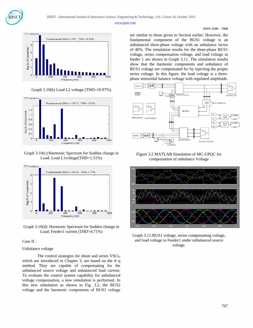
The control strategies for shunt and series VSCs, which are introduced in Chapter 3, are based on the d–q method. They are capable of compensating for the unbalanced source voltage and unbalanced load current. To evaluate the control system capability for unbalanced voltage compensation, a new simulation is performed. In this new simulation as shown in Fig. 3.2, the BUS2 voltage and the harmonic components of BUS1 voltage
are similar to those given in Section earlier. However, the fundamental component of the BUS1 voltage is an unbalanced three-phase voltage with an unbalance factor of 40%. The simulation results for the three-phase BUS1 voltage, series compensation voltage, and load voltage in feeder 1 are shown in Graph 3.11. The simulation results show that the harmonic components and unbalance of BUS1 voltage are compensated for by injecting the proper series voltage. In this figure, the load voltage is a three-phase sinusoidal balance voltage with regulated amplitude.
Figure 3.2 MATLAB Simulation of MC-UPQC for compensation of unbalance Voltage
Graph 3.11:BUS1 voltage, series compensating voltage, and load voltage in Feeder1 under unbalanced source
voltage.
767

IJISET - International Journal of Innovative Science, Engineering & Technology, Vol. 2 Issue 10, October 2015.
www.ijiset.com
ISSN 2348 – 7968
Graph 3.12: Feeder1 under unbalanced source voltage (a) Bus 1Voltage (THD=54.94%)
Graph 3.12: Feeder1 under unbalanced source voltage (b)Load voltage in feeder 1 under balanced source voltage
(THD=3.40%)
4. Conclusions Traditional power distribution system has some drawbacks in the form of power quality, such as harmonics, flicker, and imbalance, transients, voltage sag/swell, and interruption. In order to reduce these drawbacks the new configuration is named Multiconverter unified power-quality conditioner (MC-UPQC) is introduced. In this paper concern with a new configuration for simultaneous compensation of voltage and current in adjacent feeders. Compared to a conventional UPQC, the proposed topology is capable of fully protecting critical and sensitive loads against distortions, sags/swell, and interruption in two-feeder systems. Under the condition of interruption the power required by load is supplied through respected VSCs. This implies that the power semiconductor switches of VSC must be rated such that total power transfer is possible. This may increase the cost of the device, but the benefit that may be obtained can offset the expense. The cost of the MC UPQC must be
balanced against the cost of interruption, based on reliability indices, such as the customer average interruption duration index (CAIDI) and customer average interruption frequency index (CAIFI). It is expected that the MC-UPQC cost can be recovered in a few years by charging higher tariffs for the protected lines.
A power system consist of two three phase three wire 380V(rms,L-L), is designed and simulated in MATLAB Simulink. The performance of the MC-UPQC is evaluated under various disturbance conditions and it is shown that its best performance and less THD characteristic. A single phase prototype model of a 3 phase MC-UPQC selected and designed for hardware setup. It is basically a unique combination of 3 VSC’s,coupling transformer, gate drive circuit, PIC microcontroller, voltage regulator; optoisolators. The main problem which we are going to solve using this prototype model is voltage dip. Simulation and Hardware results conclude that the proposed MC-UPQC offers the following advantages:
1) Power transfer between two adjacent feeders for sag/swell and interruption compensation.
2) Compensation for interruptions without the need for a battery storage system and, consequently, without storage capacity limitation. 3) Sharing power compensation capabilities between two adjacent feeders which are not connected.
References
[1] D. D. Sabin and A. Sundaram, “Quality enhances reliability,” IEEE Spectr., vol. 33, no. 2, pp. 34–41, Feb. 1996.
[2] M. Aredes, K. Heumann, and E. H. Watanabe, “An universal active power line conditioner,” IEEE Trans. Power Del., vol. 13, no. 2, pp.545–551, Apr. 1998.
[3] F. Z. Peng, “Application issues of active power filters,” IEEE Ind. Appl. Mag., vol. 4, no. 5, pp. 21–30, Sep../Oct. 1998.
[4] L. Gyugyi, K. K. Sen, and C. D. Schauder, “Interline power flow controller concept: A new approach to power flow management in transmission systems,” IEEE Trans. Power Del., vol. 14, no. 3, pp.1115–1123, Jul. 1999.
[5] Xiao-Ping Zhang,” Modeling of the Generalized Unified Power Flow Controller (GUPFC) in a Nonlinear Interior Point OPF”,IEEE Transactions On Power Systems, VOL. 16, NO. 3, August 2001.
[6] M. A. Hannan and Azah Mohamed,” PSCAD/EMTDC Simulation of Unified Series-Shunt
Compensator for Power Quality Improvement”, IEEE Transactions on Power Delivery, Vol. 20, No. 2, April 2005.
[7] N. G. Jayanti, Malabika Basu, Michael Conlon” Rating requirements of a unified power quality conditioner (UPQC) for voltage ride through capability enhancement”, 3rd IET International Conference on Power Electronics, Machines and Drives, Dublin, Ireland, 2006, pp.632-636..
[8] Yankui Zhang, Yan Zhang, and Chen Chen,” A Novel Power Injection Model of IPFC for Power Flow Analysis Inclusive
768

IJISET - International Journal of Innovative Science, Engineering & Technology, Vol. 2 Issue 10, October 2015.
www.ijiset.com
ISSN 2348 – 7968
of Practical Constraints”, IEEE Transactions on power systems, vol. 21, NO. 4, November 2006
[9] Khadkikar, V.,Chandra, A. ; Barry, A.O. ; Nguyen, T.D ,” Application of UPQC to protect a sensitive load on a polluted distribution network”, Power Engineering Society General Meeting, 2006. IEEE.
[10] A. K. Jindal, A. Ghosh, and A. Joshi, “Interline unified power quality conditioner,” IEEE Trans. Power Del., vol. 22, no. 1, pp. 364–372, Jan.2007.
[11] Valentin Azbe,Rafael Mihalic,”The Control Strategy for an IPFC Based on the Energy Function”.IEEE Transactions On Power Systems, VOL. 23, NO. 4, November 2008.
[12] Hamid Reza Mohammadi, Ali Yazdian Varjani, and Hossein Mokhtari,” Multiconverter Unified Power-Quality Conditioning System: MC-UPQC”, IEEE Transactions On Power Delivery, vol. 24, no. 3, july 2009.
[13] Eduardo Espinosa, Jos6 Espinoza, Luis Moran, Jorge Hidalgo, Javier Muiloz,” A Multi-Cell Unified Power Quality Conditioner that Operates with Asymmetrical DC Links Voltages for Minimum THD”,IEEE 2009.
[14] Vinod Khadkikar,” UPQC-S: A Novel Concept of Simultaneous Voltage Sag/Swell and Load Reactive Power Compensations Utilizing Series Inverter of UPQC, IEEE 2010.
[15] Zuquan Liang*, Bin Lu, Tai Bai, Shu Wang, Kun Liu, ShanFeng Yin, Jiamin Zhang The Decoupled Control Research of UPQC”, Elsevier Sciverse Science Direct, ICSGCE 2011: 27–30 September 2011, Chengdu, China.
[16] Bahr Eldin S. M, K. S. Rama Rao and N. Perumal,” Generalized Unified Power Quality Conditioner for Compensating Current and Voltage Imperfections”, IEEE PEDS 2011, Singapore, 5 -8 December 2011.
[17] C. Benachaibaa*, Ahmed M. A. Haidarb, M. Hababa, O. Abdelkhaleka,” Smart Control of UPQC within Microgrid Energy System”, Elsevier Science Direct Energy Procedia 6 (2011) 503–512.
[18] He Junpinga, Cui Jiaoa, Ni Zea, a,” Design and Simulation on a Novel UPQC Topology & its Control Strategy”, Elsevier Sciverse Science Direct PEEA 2011 Shenzhen, Procedia Engineering 23 (2011) 417 – 422.
[19] B. Karthik, I. Alagarasan, S. Chandrasekar,” Optimal location of interline power flow controller for controlling multi transmission line: A new integrated technique,” Higher Education Press and Springer-Verlag Berlin Heidelberg 2012.
[20] Ch. Chengaia,R. V. S. Satyanarayana,” Power Flow Assessment In Transmission Lines Using Simulink Model With UPFC”,IEEE [ICCEET],2012.
[21] Bahr Eldin S. M, K. S. Rama Rao, Rosdiazli Ibrahim, N. Perumal,” Convertible Unified Power Quality Conditioner to mitigate voltage and current imperfections”, 4th International Conference on Intelligent and Advanced Systems,IEEE 2011.
[22] B. Gopal, Pannala Krishna Murthy & G.N. Sreenivas,” A Review on UPQC for Power Quality Improvement in Distribution System”, Global Journal of Researches in Engineering Electrical and Electronics Engineering Volume 13 Issue 7 Version 1.0 Year 2013.
[23] Chandra Babu Paduchuri, Subhransu Sekhar Dash, Subramani Chinnamuthu,” A New Control Strategy Based
Multi Converter UPQC Using Fuzzy Logic Controller to Improve the Power Quality Issues”, Power Engineering And Electrical Engineering Volume: 12 Number: 2 J 2014 J June.
[24] Dr. Kurt Schipman, Dr. François Delincé,” The Importance Of Good Power Quality”, ABB Power Quality Products, Belgium.
769