performance assessment of the terma obstruction light ... · pdf fileconstruction of...
TRANSCRIPT

Performance Assessment of the Terma Obstruction Light Control System as an Aircraft Detection Lighting System June 2016 DOT/FAA/TC-TN16/41 This document is available to the U.S. public through the National Technical Information Services (NTIS), Springfield, Virginia 22161. This document is also available from the Federal Aviation Administration William J. Hughes Technical Center at actlibrary.tc.faa.gov.
U.S. Department of Transportation Federal Aviation Administration
ote
tech
nica
l no
te t
ech

NOTICE
This document is disseminated under the sponsorship of the U.S. Department of Transportation in the interest of information exchange. The United States Government assumes no liability for the contents or use thereof. The United States Government does not endorse products or manufacturers. Trade or manufacturer's names appear herein solely because they are considered essential to the objective of this report. The findings and conclusions in this report are those of the author(s) and do not necessarily represent the views of the funding agency. This document does not constitute FAA policy. Consult the FAA sponsoring organization listed on the Technical Documentation page as to its use. This report is available at the Federal Aviation Administration William J. Hughes Technical Center’s Full-Text Technical Reports page: actlibrary.tc.faa.gov in Adobe Acrobat portable document format (PDF).

Technical Documentation Page 1. Report No.
DOT/FAA/TC-TN16/41 2. Government Accession No. 3. Recipient's Catalog No.
4. Title and Subtitle PERFORMANCE ASSESSMENT OF THE TERMA OBSTRUCTION LIGHT CONTROL SYSTEM AS AN AIRCRAFT DETECTION LIGHTING SYSTEM
5. Report Date June 2016
6. Performing Organization Code ANG-E26
7. Author(s) James Patterson, Jr.* and Garrison Canter**
8. Performing Organization Report No.
9. Performing Organization Name and Address 10. Work Unit No. (TRAIS) *Federal Aviation Administration **SRA International, Inc. William J. Hughes Technical Center A CSRA Company Aviation Research Division 1201 New Road Airport Technology R&D Branch Suite 242 Atlantic City International Airport, NJ 08405 Linwood, NJ 08221
11. Contract or Grant No.
12. Sponsoring Agency Name and Address U.S. Department of Transportation Federal Aviation Administration Airport Engineering Division 800 Independence Ave. SW Washington, DC 20591
13. Type of Report and Period Covered Technical Note
14. Sponsoring Agency Code AAS-100
15. Supplementary Notes Mike DiPilato, of CSRA International Inc., provided technical support during this performance assessment. 16. Abstract Federal Aviation Administration (FAA) Airport Technology Research and Development Branch (ATR) personnel conducted a performance assessment of the Terma Obstruction Light Control (OLC) System. The purpose of this assessment was to determine if the Terma OLC system meets the aircraft detection lighting system requirements specified in FAA Advisory Circular (AC) 70/7460-1L, “Obstruction Marking and Lighting,” Chapter 14 Aircraft Detection Lighting Systems. FAA ATR personnel assessed the Terma OLC at the Tehachapi Wind Resource Area, located near Mojave, California. This performance assessment, consisting of demonstrations, flight testing, and data analysis was conducted on April 15, 2015. In the performance assessment, a series of flight patterns were flown against the Terma OLC system to demonstrate whether it could meet the FAA performance requirements specified in AC 70/7460-1L. The Terma OLC system performed according to the manufacturer’s specifications and met the performance requirements identified in AC 70/7460-1L. 17. Key Words
Aircraft Detection Lighting System, Obstruction light control, Obstruction lighting, Terma, ADLS
18. Distribution Statement
This document is available to the U.S. public through the National Technical Information Service (NTIS), Springfield, Virginia 22161. This document is also available from the Federal Aviation Administration William J. Hughes Technical Center at actlibrary.tc.faa.gov.
19. Security Classif. (of this report) Unclassified
20. Security Classif. (of this page) Unclassified
21. No. of Pages 44
22. Price
Form DOT F 1700.7 (8-72) Reproduction of completed page authorized.
iii
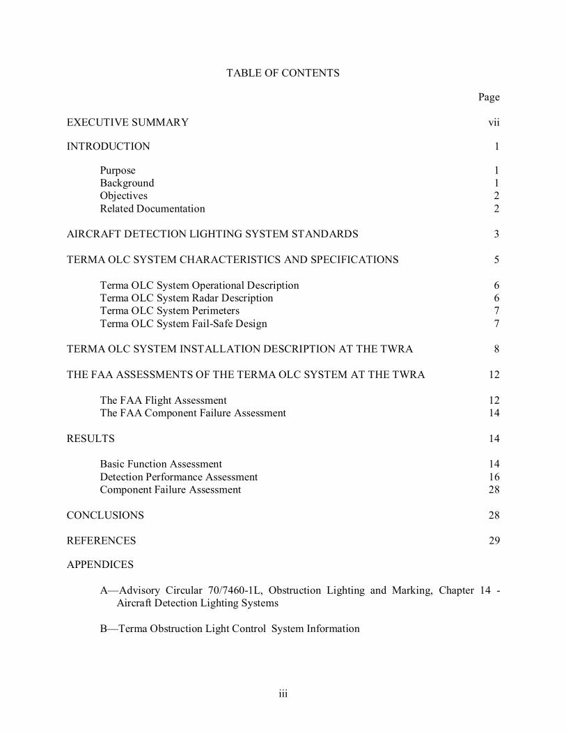
TABLE OF CONTENTS
Page
EXECUTIVE SUMMARY vii
INTRODUCTION 1
Purpose 1 Background 1 Objectives 2 Related Documentation 2
AIRCRAFT DETECTION LIGHTING SYSTEM STANDARDS 3 TERMA OLC SYSTEM CHARACTERISTICS AND SPECIFICATIONS 5
Terma OLC System Operational Description 6 Terma OLC System Radar Description 6 Terma OLC System Perimeters 7 Terma OLC System Fail-Safe Design 7
TERMA OLC SYSTEM INSTALLATION DESCRIPTION AT THE TWRA 8
THE FAA ASSESSMENTS OF THE TERMA OLC SYSTEM AT THE TWRA 12
The FAA Flight Assessment 12 The FAA Component Failure Assessment 14
RESULTS 14
Basic Function Assessment 14 Detection Performance Assessment 16 Component Failure Assessment 28
CONCLUSIONS 28 REFERENCES 29
APPENDICES
A—Advisory Circular 70/7460-1L, Obstruction Lighting and Marking, Chapter 14 - Aircraft Detection Lighting Systems
B—Terma Obstruction Light Control System Information
iv
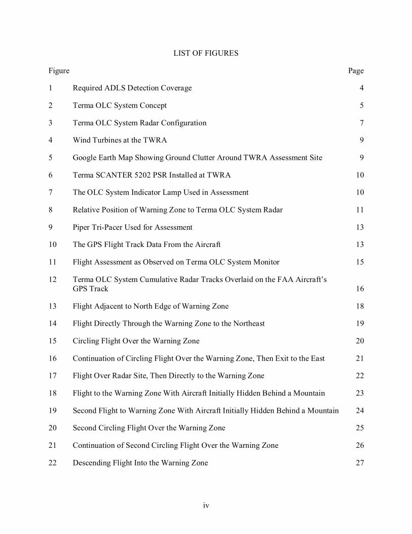
LIST OF FIGURES
Figure Page
1 Required ADLS Detection Coverage 4
2 Terma OLC System Concept 5
3 Terma OLC System Radar Configuration 7
4 Wind Turbines at the TWRA 9
5 Google Earth Map Showing Ground Clutter Around TWRA Assessment Site 9
6 Terma SCANTER 5202 PSR Installed at TWRA 10
7 The OLC System Indicator Lamp Used in Assessment 10
8 Relative Position of Warning Zone to Terma OLC System Radar 11
9 Piper Tri-Pacer Used for Assessment 13
10 The GPS Flight Track Data From the Aircraft 13
11 Flight Assessment as Observed on Terma OLC System Monitor 15
12 Terma OLC System Cumulative Radar Tracks Overlaid on the FAA Aircraft’s GPS Track 16
13 Flight Adjacent to North Edge of Warning Zone 18
14 Flight Directly Through the Warning Zone to the Northeast 19
15 Circling Flight Over the Warning Zone 20
16 Continuation of Circling Flight Over the Warning Zone, Then Exit to the East 21
17 Flight Over Radar Site, Then Directly to the Warning Zone 22
18 Flight to the Warning Zone With Aircraft Initially Hidden Behind a Mountain 23
19 Second Flight to Warning Zone With Aircraft Initially Hidden Behind a Mountain 24
20 Second Circling Flight Over the Warning Zone 25
21 Continuation of Second Circling Flight Over the Warning Zone 26
22 Descending Flight Into the Warning Zone 27

v
LIST OF TABLES Table Page 1 The GPS Coordinates of Terma OLC PSR and Warning Zone at TWRA 11

vi
LIST OF ACRONYMS
AC Advisory Circular ADLS Aircraft detection lighting system AGL Above ground level ATR Airport Technology Research and Development Branch BITE Built-in test equipment CFR Code of Federal Regulations FAA Federal Aviation Administration FCC Federal Communications Commission GPS Global positioning system IP Internet protocol NM Nautical mile OLC Obstruction light control PSR Primary surveillance radar SCADA Supervisory control and data acquisition SM Statute mile TWRA Tehachapi Wind Resource Area
vii/viii
EXECUTIVE SUMMARY
Federal Aviation Administration (FAA) Airport Technology Research and Development Branch (ATR) personnel conducted a performance assessment of the Terma Obstruction Light Control (OLC) system. The purpose of this assessment was to determine if the Terma OLC system meets the aircraft detection lighting system (ADLS) requirements specified in FAA Advisory Circular (AC) 70/7460-1L, “Obstruction Marking and Lighting,” Chapter 14 – Aircraft Lighting Detection Systems. Aircraft detection lighting systems continuously monitor the airspace around an obstruction or group of obstructions for aircraft; and when the detection system detects an aircraft in its airspace, the system sends an electronic signal to the lighting control unit, which turns on the lights. Once the aircraft clears the obstruction area and there is no longer a risk of collision, the detection system turns off the lights and the system returns to standby mode. The United States has experienced a steady increase in the number of applications for construction of telecommunication towers and wind turbines. Any temporary or permanent structure, including telecommunication towers and wind turbines, that exceeds an overall height of 200 feet (61 meters) above ground level or exceeds any obstruction standard contained in Title 14 Code of Federal Regulations Part 77, “Safe, Efficient Use, and Preservation of the Navigable Airspace,” should be marked and/or lighted with FAA-approved paint markings or lighting fixtures to ensure that they are visible to pilots at night. Due to the number of existing telecommunication towers and wind turbines, combined with expected future construction, the number of obstructions that have these required lighting fixtures has greatly increased. As a result, it has created a light pollution nuisance to residents living near these obstructions. Using an ADLS could have a positive impact on this problem, while still providing a sufficient level of safety for pilots operating at night in the vicinity of these obstructions. FAA ATR personnel assessed the Terma OLC system at the Tehachapi Wind Resource Area, located near Mojave, California. This performance assessment, consisting of demonstrations, flight testing, and data analysis was conducted on April 15, 2015. In the performance assessment, a series of flight patterns were flown against the Terma OLC system to demonstrate whether it could meet the FAA performance requirements specified in AC 70/7460-1L. The Terma OLC system performed according to the manufacturer’s specifications and met the performance requirements identified in AC 70/7460-1L.

1
INTRODUCTION
PURPOSE.
Federal Aviation Administration (FAA) Airport Technology Research and Development Branch (ATR) personnel conducted a performance assessment of an aircraft detection lighting system (ADLS) developed by Terma, referred to herein as Terma obstruction light control (OLC) system. The purpose of this assessment was to determine if the Terma OLC system meets the ADLS requirements specified in Chapter 14 of FAA Advisory Circular (AC) 70/7460-1L, “Obstruction Marking and Lighting.” [1] BACKGROUND.
In recent years, several companies have developed detection systems that monitor the airspace around an obstruction or group of obstructions to automatically turn the obstruction lighting on or off as needed. Such systems continuously monitor the airspace around their location; and when the detection system detects an aircraft in its airspace, the system sends an electronic signal to the lighting control unit, which turns on the lights. Once the aircraft clears the obstruction area and there is no longer a risk of collision, the ADLS turns the lights off and the system returns to standby mode. These detection systems are typically (1) mounted directly on the obstruction, (2) positioned on a dedicated tower close to the obstruction, or (3) mounted on a stand-alone structure located in the vicinity of the obstruction at an optimized vantage point to ensure that the sensor can cover the entire volume of airspace around the obstruction. In addition to controlling the obstruction lighting, some vendors have suggested using supplemental warning tools, such as an audible warning message or supplemental lighting that catches the pilot’s attention, thereby providing an additional warning to the pilot that they are operating in close proximity to an obstruction. The United States has experienced a steady increase in the number of applications for construction of telecommunication towers and wind turbines, partially because of government mandates to improve the nation’s emergency communication network and to increase the amount of renewable energy generation. These telecommunication towers and wind turbines have begun to heavily occupy almost every corner of the country. Projections show that the accelerated rate of construction will continue well into the next decade. Any temporary or permanent structure, including these telecommunication towers and wind turbines, that exceeds an overall height of 200 ft (61 m) above ground level (AGL) or exceeds any obstruction standard contained in Title 14 Code of Federal Regulations (CFR) Part 77, “Safe, Efficient Use, and Preservation of the Navigable Airspace,” [2] should be marked and/or lighted with FAA-approved paint markings or lighting fixtures to ensure that they are visible to pilots. Due to the number of existing telecommunication towers and wind turbines, combined with the expected construction of new structures, the number of obstructions that have FAA-required light fixtures has greatly increased. As a result, it has created a light pollution nuisance to residents living near these obstructions. Using an ADLS could have a positive impact on this problem, while still providing a sufficient level of safety for pilots operating at night in the vicinity of these obstructions. From 2011 to 2015, ATR personnel have worked closely with several ADLS vendors to better understand the technologies, their capabilities, and the level of performance that would be

2
necessary to safely integrate this concept into the National Airspace System. One major milestone achieved during the ADLS standards development was to enable the sensors to detect aircraft beyond the required 3 nautical miles (NM) from the obstruction, which would ensure that the lighting was on and the pilot was able to visually acquire the lights 3 NM away from the obstruction. The 3-NM visibility requirement is important because it ties directly to the inflight visibility requirements for a flight conducted under Visual Flight Rules. In 2013, ATR personnel first developed standards for ADLS that were based on technical reviews, discussions, and flight tests of ADLS in the United States and Canada. These ATR-developed standards have since been used by the FAA as the baseline to which new ADLSs, like the Terma OLC system, were tested against. The ATR-developed standards have since been integrated into AC 70/7460-1L as Chapter 14, titled “Aircraft Detection Lighting Systems,” which was published in December 2015 [1]. OBJECTIVES.
The overall objective of this assessment was to conduct a performance assessment of the Terma OLC system according to the requirements and standards for ADLSs in Chapter 14 of AC 70/7460-1L. This technical note describes the performance assessment of the Terma OLC system conducted at the Tehachapi Wind Resource Area (TWRA), located near Mojave, California. RELATED DOCUMENTATION.
The guidelines that have been in place for obstruction marking and lighting have remained mostly unchanged for the last 10 to 20 years and have proved to be sufficient for warning pilots of the presence of an obstruction. The recent update of AC 70/7460-1L does, however, include new material that is designed to improve safety, and at the same time, attempts to reduce the impact of obstruction lighting on nearby communities and wildlife. The introduction of ADLS suggests that the traditional obstruction lights remain the same in intensity, flash rate, and performance, but that the lights can be controlled by an automatic radar-activated monitoring system. The following FAA documents provide a significant amount of information and guidance pertaining to the lighting of obstructions: • AC 150/5345-43, “Specification for Obstruction Lighting Equipment.”
This document specifies the lighting equipment and fixtures that should be used for lighting obstructions. The color of the light, flash rate, intensity, and various electrical and performance requirements are all addressed in this document. Obstruction lights are given “L” type designations, which are described in this AC. The performance characteristics for the particular lights mentioned in this assessment are as follows:

3
- L-864—Red flashing obstruction light, 2000 peak Candela, a minimum 750 Candela, with a 3-degree vertical beam spread, flashing at a rate between 20 and 40 flashes per minute. This light is required on wind turbines.
• FAA Technical Note DOT/FAA/TC-TN12/9, “Evaluation of New Obstruction Lighting
Techniques to Reduce Avian Fatalities,” James W. Patterson, Jr., May 2012.
This document describes research conducted by FAA ATR personnel in which researchers evaluated a proposal to omit or flash the normally steady-burning red obstruction lights as a way to mitigate their impact on birds, due to their unique color and flash pattern.
AIRCRAFT DETECTION LIGHTING SYSTEM STANDARDS
Based on the result of research efforts conducted by FAA ATR personnel, Chapter 14 of AC 70/7460-1L is the first fully comprehensive set of standards for ADLSs that has been published worldwide. Earlier research efforts in Canada and the United States led to the development of a few sets of very ambiguous descriptions of the technology, but it did not provide any specific guidance on the required range, coverage area, detection target size, or operational requirements for the technology. The following are the key ADLS operational requirements introduced in Chapter 14 of AC 70/7460-1L [1], which is included in its entirety in appendix A.
1. The system should be designed with sufficient sensors to provide complete detection
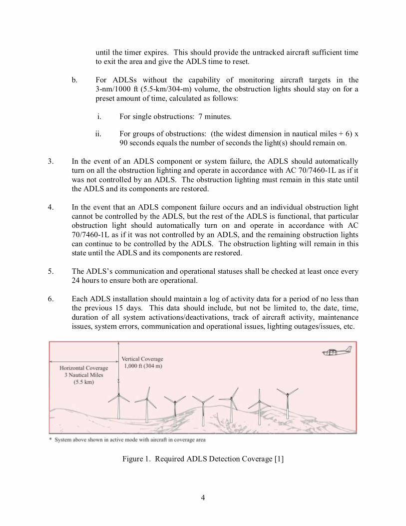
coverage for aircraft that enter a three-dimensional volume of airspace, or coverage area, around the obstruction(s) (see figure 1), as follows:
a. Horizontal detection coverage should provide for obstruction lighting to be
activated and illuminated prior to aircraft penetrating the perimeter of the volume, which is a minimum of 3 NM (5.5 km) away from the obstruction or the perimeter of a group of obstructions.
b. Vertical detection coverage should provide for obstruction lighting to be activated and illuminated prior to aircraft penetrating the volume, which extends from the ground up to 1000 ft (304 m) above the highest part of the obstruction or group of obstructions, for all areas within the 3-NM (5.5-km) perimeter defined above.
2. The ADLS should activate the obstruction lighting system in sufficient time to allow the
lights to illuminate and synchronize to flash simultaneously prior to an aircraft penetrating the volume defined above. The lights should remain on for a specific time period, as follows:
a. For ADLSs capable of continuously monitoring aircraft while they are within the
3-NM/1000-ft (5.5-km/304-m) volume, the obstruction lights should stay on until the aircraft exits the volume. In the event detection of the aircraft is lost while being continuously monitored within the 3-NM/1000-ft (5.5-km/304-m) volume, the ADLS should initiate a 30-minute timer and keep the obstruction lights on
4
until the timer expires. This should provide the untracked aircraft sufficient time to exit the area and give the ADLS time to reset.
b. For ADLSs without the capability of monitoring aircraft targets in the
3-nm/1000 ft (5.5-km/304-m) volume, the obstruction lights should stay on for a preset amount of time, calculated as follows: i. For single obstructions: 7 minutes.
ii. For groups of obstructions: (the widest dimension in nautical miles + 6) x 90 seconds equals the number of seconds the light(s) should remain on.
3. In the event of an ADLS component or system failure, the ADLS should automatically
turn on all the obstruction lighting and operate in accordance with AC 70/7460-1L as if it was not controlled by an ADLS. The obstruction lighting must remain in this state until the ADLS and its components are restored.
4. In the event that an ADLS component failure occurs and an individual obstruction light
cannot be controlled by the ADLS, but the rest of the ADLS is functional, that particular obstruction light should automatically turn on and operate in accordance with AC 70/7460-1L as if it was not controlled by an ADLS, and the remaining obstruction lights can continue to be controlled by the ADLS. The obstruction lighting will remain in this state until the ADLS and its components are restored.
5. The ADLS’s communication and operational statuses shall be checked at least once every
24 hours to ensure both are operational. 6. Each ADLS installation should maintain a log of activity data for a period of no less than
the previous 15 days. This data should include, but not be limited to, the date, time, duration of all system activations/deactivations, track of aircraft activity, maintenance issues, system errors, communication and operational issues, lighting outages/issues, etc.
Figure 1. Required ADLS Detection Coverage [1]

5
In 2014, FAA ATR personnel completed an ADLS assessment, with the objective of validating the ADLS standards in AC 70/7460-1L. This assessment is described in FAA Technical Note DOT/FAA/TC-TN15/54, “Performance Assessment of the Laufer Wind Aircraft Detection System as an Aircraft Detection Lighting System.” This technical note concluded the following:
…the performance requirements provided in AC 70/7460-1L for ADLSs remain valid and provide for a technology that offers a satisfactory level of safety for the flying public, while at the same time, reduces the impact of obstruction lights on nearby communities and migratory bird populations. [3]
Chapter 14 of AC 70/7460-1L also contains language that allows for ADLSs to have an optional voice/audio feature that transmits a low-power, audible warning message over an aviation frequency licensed by the Federal Communications Commission (FCC) in the MULTICOM/UNICOM frequency band to provide pilots additional information on the obstruction they are approaching. The Terma OLC system does not offer this option, so these requirements do not apply to this assessment.
TERMA OLC SYSTEM CHARACTERISTICS AND SPECIFICATIONS
The Terma OLC system uses a SCANTER 5202 primary surveillance radar (PSR) to detect aircraft within range of a wind farm or obstruction area and follows the general description provided in AC 70/7460-1L. For instance, when there are no aircraft in the vicinity of the wind turbine farm or obstruction, the warning lights remain off. When aircraft are detected in the vicinity, the lights are activated (turned on). When all aircraft have safely left the vicinity, the lights are deactivated (turned off). The Terma OLC system allows wind turbine farm warning lights to remain safely off at night when aircraft are not in the area. As shown in figure 2, Terma’s OLC system concept consists of one or more SCANTER 5202 PSR system, including an antenna and a global positioning system (GPS) synchronized light control connected via a supervisory control and data acquisition (SCADA) internet protocol (IP) network [4].
Figure 2. Terma OLC System Concept [4]
6
TERMA OLC SYSTEM OPERATIONAL DESCRIPTION.
The Terma OLC system operates as follows:
1. Prior to reaching the light activation perimeter of the warning zone (3-NM/1000-ft (5.5-km/304-m) volume), aircraft are detected and tracked by the SCANTER 5202 PSR(s).
2. The PSR sends a signal through the SCADA IP network to the GPS Synchronized OLC
system when the aircraft reaches the light activation perimeter of the warning zone.
3. The OLC system turns on the obstruction light(s).
4. The PSR tracks the aircraft until it exits the warning zone light activation perimeter (3-NM/1000-ft (5.5-km/304-m) volume).
5. The OLC system determines when to turn the lights off after verifying that no aircraft are
within the warning zone. TERMA OLC SYSTEM RADAR DESCRIPTION.
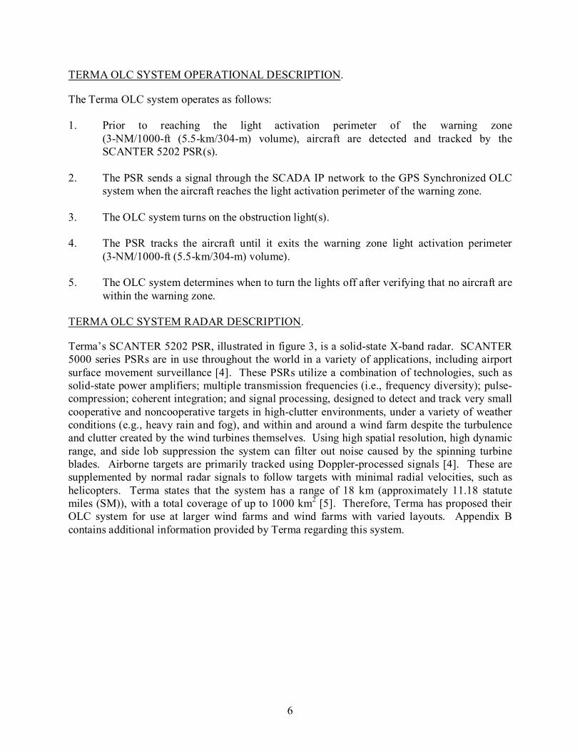
Terma’s SCANTER 5202 PSR, illustrated in figure 3, is a solid-state X-band radar. SCANTER 5000 series PSRs are in use throughout the world in a variety of applications, including airport surface movement surveillance [4]. These PSRs utilize a combination of technologies, such as solid-state power amplifiers; multiple transmission frequencies (i.e., frequency diversity); pulse-compression; coherent integration; and signal processing, designed to detect and track very small cooperative and noncooperative targets in high-clutter environments, under a variety of weather conditions (e.g., heavy rain and fog), and within and around a wind farm despite the turbulence and clutter created by the wind turbines themselves. Using high spatial resolution, high dynamic range, and side lob suppression the system can filter out noise caused by the spinning turbine blades. Airborne targets are primarily tracked using Doppler-processed signals [4]. These are supplemented by normal radar signals to follow targets with minimal radial velocities, such as helicopters. Terma states that the system has a range of 18 km (approximately 11.18 statute miles (SM)), with a total coverage of up to 1000 km2 [5]. Therefore, Terma has proposed their OLC system for use at larger wind farms and wind farms with varied layouts. Appendix B contains additional information provided by Terma regarding this system.

7
Figure 3. Terma OLC System Radar Configuration [4]
TERMA OLC SYSTEM PERIMETERS.
Terma’s OLC system includes three zones to ensure adequate identification of obstructions and compliance with AC 70/7460-1L: • Outer Detection Zone: Aircraft are detected and tracked by radar in this area, but the
obstruction lights are not turned on until one of the aircraft enters the warning zone.
• Inner Warning Zone: Lights in the Obstruction Area are activated when aircraft enter this zone, and the lights remain lit while any aircraft is within this area. This zone will be located a minimum of 3 NM (5.5 km) away from the obstruction or the perimeter of a group of obstructions.
• Obstruction Area: This is a broadly defined area that includes lighted obstruction(s),
such as a wind farm. TERMA OLC SYSTEM FAIL-SAFE DESIGN.
The Terma OLC system includes multiple self-testing functions to provide fail-safe protection. When a failure occurs, the obstruction lights are turned on until the Terma OLC system and its components functions are restored [6]. Built-in test equipment (BITE) in the Terma OLC system provides continuous system status monitoring. The BITE monitors mains-on time, solid-state

8
power amplifier status, forward power, noise figure, internal voltages and temperatures, turning unit status, and other parameters. Diagnostic tests are performed when the system starts up, including the following [6]: • Module presence test • Data link test • Memory test of all circuits The BITE also reports the following when monitoring the system during operation [6]: • BITE errors/warnings • Signal activity and processes • Connectivity to OLC system • Internal supply voltages • Noise figure, internal voltages, and temperatures • Forward power • Reverse power • Status from motor, gear, and optional inputs providing antenna status • Temperatures • Internal power supplies The status of each BITE parameter is assessed automatically to ensure consistent operation. If any parameter is detected outside of normal operating specifications, error messages are automatically sent through the IP network interface and all obstruction lights are activated. Error records are stored automatically by the system in a log for future inspection [6].
TERMA OLC SYSTEM INSTALLATION DESCRIPTION AT THE TWRA
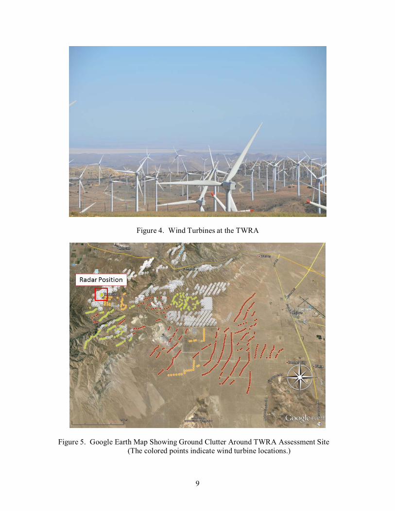
Terma installed its OLC system at the TWRA, located near Mojave, California. The TWRA is a large wind turbine farm on and around the Tehachapi Mountains containing a mix of turbines manufactured by different vendors. Examples of the wind turbines installed in the TWRA are shown in figure 4. This is a challenging radar coverage environment due to the mountainous terrain and ground clutter caused by the quantity of wind turbines. For example, figure 5 shows the locations of individual wind turbines in the vicinity of the assessment site, which are represented by colored points. The position of the radar is indicated by a red rectangle. It should be noted that for this assessment, the dimensions of the warning zone did not meet the requirement of extending at least 3 NM from the obstruction area as called for in AC 70/7460-1L. This was due to the assessment focusing on the system’s ability to activate an indicator lamp when an aircraft was detected in a given area, rather than monitoring the activation of lighting on a specific obstruction or group of obstructions.
9
Figure 4. Wind Turbines at the TWRA
Figure 5. Google Earth Map Showing Ground Clutter Around TWRA Assessment Site (The colored points indicate wind turbine locations.)
10
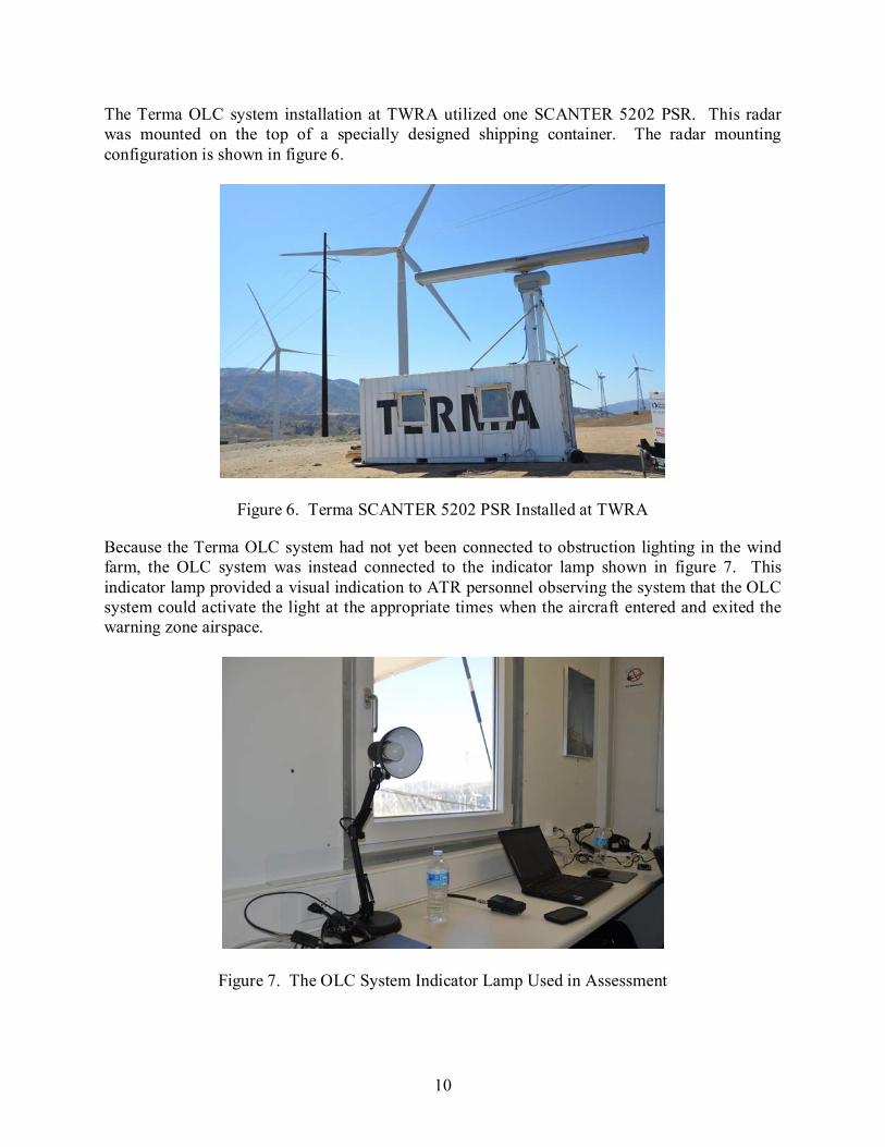
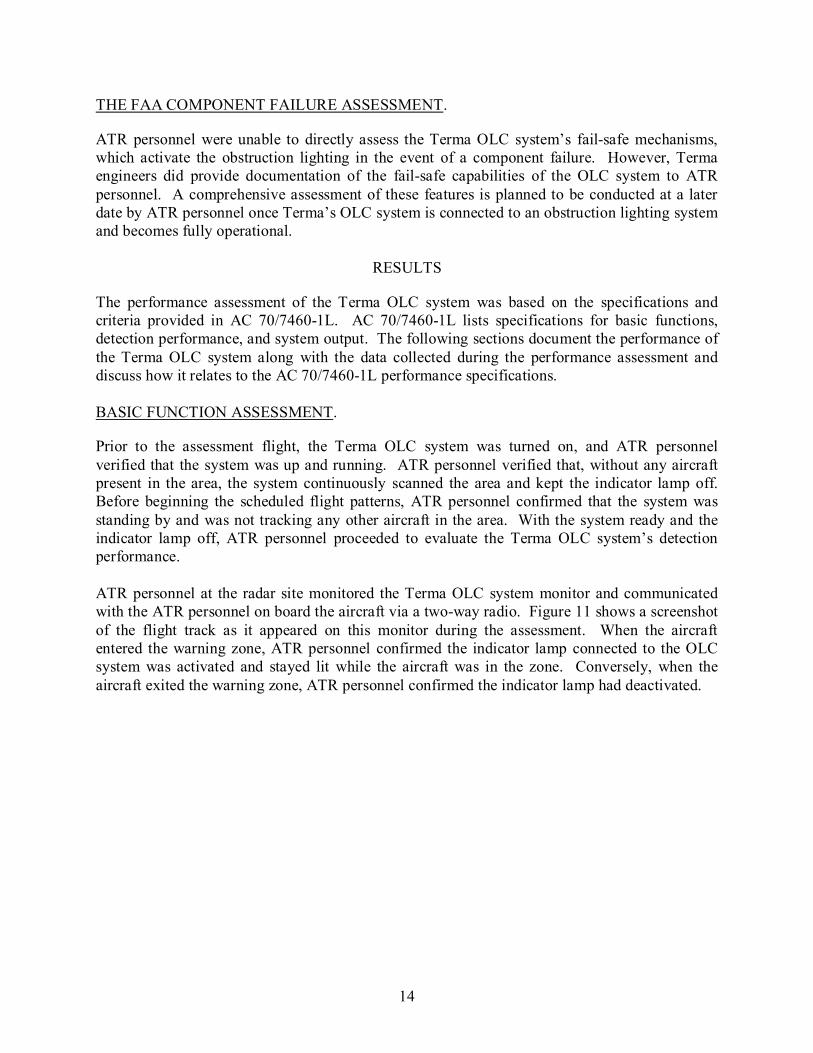
The Terma OLC system installation at TWRA utilized one SCANTER 5202 PSR. This radar was mounted on the top of a specially designed shipping container. The radar mounting configuration is shown in figure 6.
Figure 6. Terma SCANTER 5202 PSR Installed at TWRA
Because the Terma OLC system had not yet been connected to obstruction lighting in the wind farm, the OLC system was instead connected to the indicator lamp shown in figure 7. This indicator lamp provided a visual indication to ATR personnel observing the system that the OLC system could activate the light at the appropriate times when the aircraft entered and exited the warning zone airspace.
Figure 7. The OLC System Indicator Lamp Used in Assessment

11
The yellow polygon shown in figure 8 depicts the perimeter of the warning zone used for the assessment. This warning zone was 2 SM long and 1 SM wide, and the center of the zone was located approximately 4.5 NM southeast of the radar position. Although the size of this warning zone did not meet the 3-NM (5.5-km) perimeter requirement of AC 70/7460-1L, Terma’s engineers indicated that the perimeter could be expanded as needed to fully encompass the required airspace volume. The reduced size of the warning zone allowed ATR personnel to conduct performance assessments with greater efficiency due to there being less distance to cover when flying through the zone. Table 1 provides the coordinates of Terma OLC system radar position and four corners of the warning zone used for the assessment.
Figure 8. Relative Position of Warning Zone to Terma OLC System Radar
Table 1. The GPS Coordinates of Terma OLC PSR and Warning Zone at TWRA
Location Latitude Longitude Terma OLC PSR SCANTER Radar 35°03'56.03"N 118° 23'02.96"W Warning Zone – North Corner 35°02'05.39"N 118° 18'25.55"W Warning Zone – East Corner 35°01'45.22"N 118° 17'23.33"W Warning Zone – South Corner 35°00'21.07"N 118° 18'53.02"W Warning Zone – West Corner 35°00'45.85"N 118° 19'53.01"W

12
THE FAA ASSESSMENTS OF THE TERMA OLC SYSTEM AT THE TWRA
THE FAA FLIGHT ASSESSMENT.
To properly assess the performance of the Terma OLC system, ATR personnel developed a series of flight patterns to assess the system’s response to aircraft operating around the warning zone at various altitudes, flight paths, speed, etc. These flight patterns were based on similar ones conducted during a previous FAA ADLS assessment [3]. Each pattern was designed to assess a specific parameter of the ADLS to determine if the system meets the requirements in AC 70/7460-1L. Two flights were conducted, during which these six specific flight patterns were flown, in some cases multiple times. The six flight patterns are described below: 1. The aircraft flew through the center of the warning zone and exited the other side. 2. The aircraft flew inside the warning zone adjacent to its outer edge. 3. The aircraft flew over the radar site, and then flew directly to the warning zone after radar
contact was lost. 4. The aircraft completed several tight circles inside the warning zone, and then exited the
zone at a different heading from the entry heading. 5. The aircraft flew toward and over the warning zone at least 1500 ft AGL, and then
steeply descended into the warning zone. 6. The aircraft flew toward the warning zone from a location where terrain masked the
aircraft from initially being detected by the ADLS. The intent of this pattern was to identify how quickly the Terma ADLS could detect the aircraft without the benefit of early detection.
ATR personnel used the Piper PA-22 Tri-Pacer, shown in figure 9, to conduct the flight patterns. A notable characteristic of this aircraft is the outer skin of its wings and sections of fuselage is made of fabric rather than metal. The aircraft was owned and flown by a pilot with a commercial pilot certificate. All flights were operated out of the Mojave Air and Space Port, which was located approximately 20 SM southeast of the Terma OLC system installation. Figure 10 shows a Google Earth map image overlaid with the flight tracks (shown in blue) recorded by a GPS unit on board the aircraft.

13
Figure 9. Piper Tri-Pacer Used for Assessment
Figure 10. The GPS Flight Track Data From the Aircraft
14
THE FAA COMPONENT FAILURE ASSESSMENT.
ATR personnel were unable to directly assess the Terma OLC system’s fail-safe mechanisms, which activate the obstruction lighting in the event of a component failure. However, Terma engineers did provide documentation of the fail-safe capabilities of the OLC system to ATR personnel. A comprehensive assessment of these features is planned to be conducted at a later date by ATR personnel once Terma’s OLC system is connected to an obstruction lighting system and becomes fully operational.
RESULTS
The performance assessment of the Terma OLC system was based on the specifications and criteria provided in AC 70/7460-1L. AC 70/7460-1L lists specifications for basic functions, detection performance, and system output. The following sections document the performance of the Terma OLC system along with the data collected during the performance assessment and discuss how it relates to the AC 70/7460-1L performance specifications. BASIC FUNCTION ASSESSMENT.
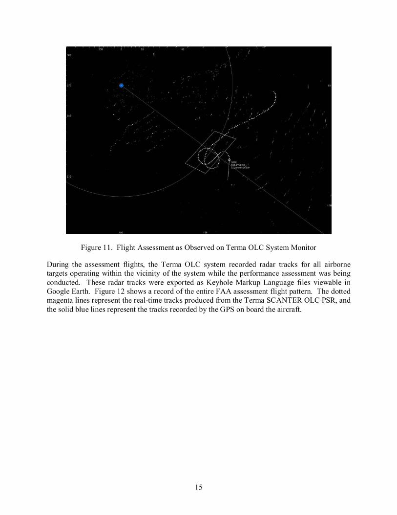
Prior to the assessment flight, the Terma OLC system was turned on, and ATR personnel verified that the system was up and running. ATR personnel verified that, without any aircraft present in the area, the system continuously scanned the area and kept the indicator lamp off. Before beginning the scheduled flight patterns, ATR personnel confirmed that the system was standing by and was not tracking any other aircraft in the area. With the system ready and the indicator lamp off, ATR personnel proceeded to evaluate the Terma OLC system’s detection performance. ATR personnel at the radar site monitored the Terma OLC system monitor and communicated with the ATR personnel on board the aircraft via a two-way radio. Figure 11 shows a screenshot of the flight track as it appeared on this monitor during the assessment. When the aircraft entered the warning zone, ATR personnel confirmed the indicator lamp connected to the OLC system was activated and stayed lit while the aircraft was in the zone. Conversely, when the aircraft exited the warning zone, ATR personnel confirmed the indicator lamp had deactivated.
15
Figure 11. Flight Assessment as Observed on Terma OLC System Monitor
During the assessment flights, the Terma OLC system recorded radar tracks for all airborne targets operating within the vicinity of the system while the performance assessment was being conducted. These radar tracks were exported as Keyhole Markup Language files viewable in Google Earth. Figure 12 shows a record of the entire FAA assessment flight pattern. The dotted magenta lines represent the real-time tracks produced from the Terma SCANTER OLC PSR, and the solid blue lines represent the tracks recorded by the GPS on board the aircraft.

16
Figure 12. Terma OLC System Cumulative Radar Tracks Overlaid on the FAA Aircraft’s GPS Track
DETECTION PERFORMANCE ASSESSMENT.
To demonstrate that the Terma OLC system was able to meet the detection performance requirements for an ADLS, ATR personnel developed and conducted a series of flight maneuvers designed to assess the system’s detection capabilities. Descriptions of the maneuvers and the results of the Terma OLC system’s detection capability are as follows: • Flight Inside the Warning Zone Adjacent to its Outer Edge
The Terma OLC system detected the aircraft 4.3 NM from the warning zone perimeter and activated the indicator lamp when the aircraft entered the warning zone. The indicator lamp deactivated as the aircraft exited the warning zone heading southwest. Figure 13 shows events 1-4 for this flight pattern.
• Flight Directly Through the Center of the Warning Zone and Exiting the Other Side
The Terma OLC system detected the aircraft 1.2 NM outside the warning zone perimeter and activated the indicator lamp when the aircraft entered the zone, flying toward the northeast. Figure 14 shows events 5-8 for this flight pattern.
• Completion of Several Tight Circles Inside the Warning Zone, Then Exiting the Zone at a Different Heading From the Entry Heading
The Terma OLC system maintained radar contact with the aircraft at a range of 2.75 NM from the warning zone and activated the indicator lamp as the aircraft entered the

17
warning zone. The system tracked the aircraft even as it conducted a series of steep circling maneuvers within the warning zone. As the aircraft exited and re-entered the zone at random headings during these turns, the Terma OLC system recognized it as the same aircraft that had entered the perimeter and activated the indicator lamp as required. Figures 15 and 16 show events 9-15 for this flight pattern.
• Flight Over the Radar Site, Then Flying Directly Through the Warning Zone After Radar Contact is Lost
The Terma OLC system lost contact with the aircraft as it flew directly over the radar site; however, this is typical of all radar systems, which are not designed to detect aircraft above the radar antenna. This gap is known as the cone of silence. Terma’s OLC system was able to re-acquire the aircraft within 1.1 NM as it flew toward the warning zone perimeter, activating the indicator lamp when the aircraft entered the perimeter. The Terma OLC system then deactivated the indicator lamp as the aircraft left the zone heading southeast. Figure 17 shows events 16-19 for this flight pattern.
• Flights to the Warning Zone From a Location Where Terrain Masked the Aircraft From Initially Being Detected by the ADLS
On two separate flights manuevers, the Terma OLC system successfully detected the aircraft as soon as it appeared from behind a mountain on the west of the warning zone. As soon as the Terma OLC system detected the aircraft (still outside the warning zone perimeter), the system continued to monitor the aircraft’s track and activated the indicator lamp when the aircraft entered the warning zone perimeter. After the aircraft flew through the warning zone and exited the area, the Terma OLC system deactivated the indicator lamp, as required. Figures 18 and 19 show events 20-26 for these flight patterns.
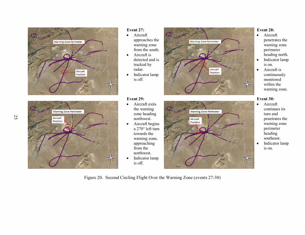
• Circling Flight Over the Warning Zone (second flight)
During a second flight, the Terma OLC system again detected and maintained contact with the aircraft as it circled inside the warning zone, activating and deactivating the indicator lamp as required when the aircraft exited and re-entered the zone. Figures 20 and 21 show events 27-32 for this flight pattern.
• Flight to and Over the Radar Site, Then Steeply Descending Into the Warning Zone
Although contact with the aircraft was lost as it flew directly over the radar site and steeply descended behind mountains as it approached the warning zone, the Terma OLC system detected the aircraft with enough time to activate the indicator lamp as it entered the warning zone perimeter. After the aircraft completed the descent and exited the area, the Terma OLC system deactivated the indicator lamp as required. Figure 22 shows events 33-36 for this flight pattern.

18
Event 1: • Aircraft
approaches the warning zone from the northeast.
• Indicator lamp is off.
Event 2: • Aircraft is
detected and tracked by radar prior to reaching the warning zone.
• Indicator lamp is off.
Event 3: • Aircraft
penetrates the warning zone perimeter heading west.
• Indicator lamp is on.
• Aircraft is continuously monitored within the warning zone.
Event 4: • Aircraft exits
the warning zone to the west.
• Indicator lamp is off.
Figure 13. Flight Adjacent to North Edge of Warning Zone (events 1-4)

19
Event 5: • Aircraft
approaches the warning zone from the southwest.
• Indicator lamp is off.
Event 6: • Aircraft is
detected and tracked by radar prior to reaching the warning zone.
• Indicator lamp is off.
Event 7: • Aircraft
penetrates the warning zone perimeter heading northeast.
• Indicator lamp is on.
• Aircraft is continuously monitored within the warning zone.
Event 8: • Aircraft exits
the warning zone to the northeast.
• Indicator lamp is off.
Figure 14. Flight Directly Through the Warning Zone to the Northeast (events 5-8)

20
Event 9: • Aircraft
approaches the warning zone from the northeast.
• Indicator lamp is off.
Event 10: • Aircraft is
detected and is tracked by radar prior to reaching the warning zone.
• Indicator lamp is off.
Event 11: • Aircraft
penetrates the warning zone perimeter heading to the southwest.
• Indicator lamp is on.
• Aircraft is continuously monitored within the warning zone.
Event 12: • Aircraft
initiates a 540° left turn, exiting the warning zone to the southeast.
• Indicator lamp is off.
Figure 15. Circling Flight Over the Warning Zone (events 9-12)

21
Event 13: • Aircraft
continues its left turn outside the warning zone.
• Indicator lamp is off.
Event 14: • Aircraft
penetrates the warning zone perimeter and continues its 540° left turn inside the warning zone.
• Indicator lamp is on.
• Aircraft is continuously monitored within the warning zone.
Event 15: • Aircraft begins
a right turn, exiting the warning zone to the east.
• Indicator lamp is off.
Figure 16. Continuation of Circling Flight Over the Warning Zone, Then Exit to the East (events 13-15)

22
Event 16: • Aircraft flies
directly over the radar site, makes a 180° turn and begins to approach the warning zone from the northwest.
• Indicator lamp is off.
Event 17: • Aircraft is
reacquired and tracked by radar prior to reaching the warning zone.
• Indicator lamp is off.
Event 18: • Aircraft
penetrates the warning zone perimeter heading southeast.
• Indicator lamp is on.
• Aircraft is continuously monitored within the warning zone.
Event 19: • Aircraft and
exits the warning zone to the southeast.
• Indicator lamp is off.
Figure 17. Flight Over Radar Site, Then Directly to the Warning Zone (events 16-19)

23
Event 20: • Aircraft
approaches the warning zone from the southwest then suddenly appears from behind the mountain.
• Indicator lamp is off.
Event 21: • Aircraft is
detected and is tracked by radar shortly before entering the warning zone.
• Aircraft penetrates the warning zone perimeter heading northeast.
• Indicator lamp is on.
Event 22: • Aircraft is
continuously monitored within the warning zone.
• Aircraft exits the warning zone to the northeast.
• Indicator lamp is off.
Figure 18. Flight to the Warning Zone With Aircraft Initially Hidden Behind a Mountain (events 20-22)

24
Event 23: • Aircraft
approaches the warning zone from the southwest then suddenly appears from behind the mountain.
• Indicator lamp is off.
Event 24: • Aircraft is
detected and is tracked by radar.
• Indicator lamp is off.
Event 25: • Aircraft
penetrates the warning zone perimeter.
• Indicator lamp is on.
• Aircraft is continuously monitored within the warning zone.
Event 26: • Aircraft exits
the warning zone to the southeast.
• Indicator lamp is off.
Figure 19. Second Flight to Warning Zone With Aircraft Initially Hidden Behind a Mountain (events 23-26)
25
Event 27: • Aircraft
approaches the warning zone from the south.
• Aircraft is detected and is tracked by radar.
• Indicator lamp is off.
Event 28: • Aircraft
penetrates the warning zone perimeter heading north.
• Indicator lamp is on.
• Aircraft is continuously monitored within the warning zone.
Event 29: • Aircraft exits
the warning zone heading northwest.
• Aircraft begins a 270° left turn towards the warning zone, approaching from the northwest.
• Indicator lamp is off.
Event 30: • Aircraft
continues its turn and penetrates the warning zone perimeter heading southeast.
• Indicator lamp is on.
Figure 20. Second Circling Flight Over the Warning Zone (events 27-30)

26
Event 31: • Aircraft
continues the 270° left turn inside the warning zone.
• Aircraft is continuously monitored within the warning zone.
• Indicator lamp is on.
Event 32: • Aircraft exits
the warning zone to the north.
• Indicator lamp is off.
Figure 21. Continuation of Second Circling Flight Over the Warning Zone (events 31-32)

27
Event 33: • Aircraft flies
over the radar site.
• Radar contact is lost.
• Indicator lamp is off.
Event 34: • Aircraft
approaches warning zone from the northwest.
• Aircraft is not yet detected by radar.
• Indicator lamp is off.
Event 35: • Aircraft is
detected by radar prior to reaching warning zone.
• Aircraft descends into the zone from 1500 ft AGL heading southeast.
• Indicator lamp is on.
Event 36: • Aircraft exits
the warning zone to the southeast
• Indicator lamp is off.
Figure 22. Descending Flight Into the Warning Zone (events 33-36)
28
COMPONENT FAILURE ASSESSMENT.
To demonstrate that the Terma OLC system was able to meet the component failure requirements for an ADLS, ATR personnel conducted a series of activities designed to test the system’s component failure responses. Descriptions of the activities and the results of the Terma OLC system’s failure response are as follows: • Individual Component and Obstruction Light Control Failure
These functions were unable to be assessed due to the limited installation at the site. However, Terma engineers did provide the documentation of the fail-safe capabilities of the OLC system to ATR personnel.
• Communication and Status Monitoring
ATR personnel verified that the Terma OLC system communication and operational status were checked at least once every 24 hours to ensure both are operational.
• Target Size
ATR personnel confirmed that the Terma OLC system could detect an object with a cross-sectional area of 1 square meter or more within the detection area. This was accomplished by flying an aircraft straight toward the Terma OLC system radar unit, which resulted in the system detecting the narrow profile of the aircraft.
• Activity Log
The Terma indicated that the data could be stored for an indefinite amount of time, depending on the user’s requirement, which satisfies the 15-day requirement of AC 70/7460-1L.
• FCC Part 15 Compliance
Based on the documentation provided to the ATR personnel by the Terma engineers, it was verified that the Terma OLC system components do not use FCC Part 15 devices [7].
• Audio/Voice Option
The Terma OLC system does not currently offer a voice/audio option; therefore, this was not evaluated. As stated in AC 70/7460-1L, this is not a required ADLS component.
CONCLUSIONS
The Federal Aviation Administration (FAA) Airport Technology Research and Development Branch evaluated the Terma Obstruction Light Control (OLC) system at the Tehachapi Wind Resource Area, located near Mojave, California. A performance assessment, consisting of demonstrations, flight testing, and data analysis was conducted on April 15, 2015. In this performance assessment, a series of flight patterns were flown against the Terma OLC system to

29/30
demonstrate that it could meet the FAA’s performance requirements for aircraft detection lighting systems. The Terma OLC system performed according to the manufacturer’s specifications and met the performance requirements identified specified in FAA Advisory Circular (AC) 70/7460-1L, “Obstruction Marking and Lighting.”
REFERENCES
1. Federal Aviation Administration, “Obstruction Marking and Lighting,” Advisory Circular (AC) 70/7460-1L, December 4, 2015.
2. U.S. Federal Register, Title 14 Code of Federal Regulations, Part 77, “Safe, Efficient
Use, and Preservation of the Navigable Airspace,” Government Printing Office, Washington DC.
3. Patterson, James, Jr., “Performance Assessment of the Laufer Wind Aircraft Detection
System as an Aircraft Detection Lighting System,” FAA technical note DOT/FAA/TC-TN15/54, September 2015.
4. Terma, “Coverage Report for OLC Demo, California,” March 2015.
5. Terma, “SCANTER 5000 Radar Series Radar-Based Obstruction Light Control,” 2015.
6. Terma, “SCANTER 5202 System Features: Built-in Test Equipment,” 2015. 7. U.S. Federal Register, Title 47 Code of Federal Regulations, Part 15, “Radio Frequency
Devices,” Government Printing Office, Washington, DC.
A-1
APPENDIX A—ADVISORY CIRCULAR 70/7460-1L, CHAPTER 14, AIRCRAFT DETECTION LIGHTING SYSTEMS 1
CHAPTER 14. AIRCRAFT DETECTION LIGHTING SYSTEMS
14.1 Purpose. Aircraft Detection Lighting Systems (ADLS) are sensor-based systems designed to detect aircraft as they approach an obstruction or group of obstructions; these systems automatically activate the appropriate obstruction lights until they are no longer needed by the aircraft. This technology reduces the impact of nighttime lighting on nearby communities and migratory birds and extends the life expectancy of obstruction lights. 14.2 General Standards. 14.2.1 The system should be designed with sufficient sensors to provide complete detection coverage for aircraft that enter a three-dimensional volume of airspace, or coverage area, around the obstruction(s) (see Figure A-27 in Appendix A), as follows: 1. Horizontal detection coverage should provide for obstruction lighting to be activated and illuminated prior to aircraft penetrating the perimeter of the volume, which is a minimum of 3 NM (5.5 km) away from the obstruction or the perimeter of a group of obstructions. 2. Vertical detection coverage should provide for obstruction lighting to be activated and illuminated prior to aircraft penetrating the volume, which extends from the ground up to 1,000 feet (304 m) above the highest part of the obstruction or group of obstructions, for all areas within the 3 NM (5.5 km) perimeter defined in subparagraph 14.2.1 1 above. 3. In some circumstances, it may not be possible to meet the volume area defined above because the terrain may mask the detection signal from acquiring an aircraft target within the 3 NM (5.5 km) perimeter. In these cases, the sponsor should identify these areas in their application to the FAA for further evaluation. 4. In some situations, lighting not controlled by the ADLS may be required when the 3 NM (5.5 km) perimeter is not achievable to ensure pilots have sufficient warning before approaching the obstructions. 14.2.2 The ADLS should activate the obstruction lighting system in sufficient time to allow the lights to illuminate and synchronize to flash simultaneously prior to an aircraft penetrating the volume defined above. The lights should remain on for a specific time period, as follows: 1 Federal Aviation Administration, “Obstruction Marking and Lighting,” Advisory Circular (AC) 70/7460-1L,
December 4, 2015.
A-2
1. For ADLSs capable of continuously monitoring aircraft while they are within the 3 NM/1,000 foot (5.5 km/304 m) volume, the obstruction lights should stay on until the aircraft exits the volume. In the event detection of the aircraft is lost while being continuously monitored within the 3 NM/1,000 foot (5.5 km/304 m) volume, the ADLS should initiate a 30-minute timer and keep the obstruction lights on until the timer expires. This should provide the untracked aircraft sufficient time to exit the area and give the ADLS time to reset. 2. For ADLSs without the capability of monitoring aircraft targets in the 3 nm/1,000 foot (5.5 km/304 m) volume, the obstruction lights should stay on for a preset amount of time, calculated as follows: a. For single obstructions: 7 minutes. b. For groups of obstructions: (the widest dimension in nautical miles + 6) x 90 seconds equals the number of seconds the light(s) should remain on. 14.2.3 Acceptance of ADLS applications will be on a case-by-case basis and may be modified, adjusted, or denied based on proximity of the obstruction or group of obstructions to airports, low-altitude flight routes, military training areas, or other areas of frequent flight activity. It may be appropriate to keep certain obstructions closest to these known activity areas illuminated during the nighttime hours, while the remainder of the group’s obstruction lighting is controlled by the ADLS. 14.2.4 Project sponsors requesting ADLS use should include in their application maps or diagrams indicating the location of the proposed sensors, the range of each sensor, and a visual indication showing how each sensor’s detection arc provides the full horizontal and vertical coverage, as required under paragraph 14.2.1. In the event that detection coverage is not 100 percent due to terrain masking, project sponsors should provide multiple maps or diagrams that indicate coverage at the affected altitudes. A sample diagram is shown in Figure A-27 in Appendix A. 14.2.5 Types of ADLS Component or System Failure Events. 1. In the event of an ADLS component or system failure, the ADLS should automatically turn on all the obstruction lighting and operate in accordance with this AC as if it was not controlled by an ADLS. The obstruction lighting must remain in this state until the ADLS and its components are restored. 2. In the event that an ADLS component failure occurs and an individual obstruction light cannot be controlled by the ADLS, but the rest of the ADLS is functional, that particular obstruction light should automatically turn on and operate in accordance with this AC as if it was not controlled by an ADLS, and the remaining obstruction lights can continue to be controlled by the ADLS. The obstruction lighting will remain in this state until the ADLS and its components are restored. 3. Complete light failure should be addressed in accordance with Chapter 2 paragraph 2.4.
A-3/A-4
14.2.6 The ADLS’s communication and operational status shall be checked at least once every 24 hours to ensure both are operational. 14.2.7 The ADLS should be able to detect an aircraft with a cross-sectional area of 1 square meter or more within the volume, as required in subparagraphs 14.2.1 1 and 14.2.1 2. 14.2.8 Each ADLS installation should maintain a log of activity data for a period of no less than the previous 15 days. This data should include, but not be limited to, the date, time, duration of all system activations/deactivations, track of aircraft activity, maintenance issues, system errors, communication and operational issues, lighting outages/issues, etc. 14.2.9 Operational Frequencies. 1. Unlicensed devices (including FCC Part 15) devices cannot be used for this type of system. 2. Any frequency used for the operation of ADLS must be individually licensed through the FCC. 14.3 Voice/Audio Option. 14.3.1 ADLS may include an optional voice/audio feature that transmits a low-power, audible warning message to provide pilots additional information on the obstruction they are approaching. 14.3.2 The audible transmission should be in accordance with appropriate FAA and FCC regulations. 14.3.3 The audible transmission should be over an aviation frequency licensed by the FCC and authorized under the Code of Federal Regulations Title 47- Part 87.483 (excluding 121.5 MHz). Note: Using air traffic control frequencies in the 117.975-MHz to 137-MHz frequency band is prohibited for this operation. 14.3.4 The audible message should consist of three quick tones, followed by a verbal message that describes the type of obstruction the system is protecting. Appropriate terms to be used include tower(s), wind turbine(s), or power line(s). 14.3.5 The audible message should be repeated three times or until the system determines the aircraft is no longer within the audible warning area defined in the following paragraph. 14.3.6 The audible message should be considered as a secondary, final warning and should be activated when an aircraft is within 1/2 NM (926 m) horizontally and 500 feet (152 m) vertically of the obstruction. The use of, or variation to, the audible warning zone may occur, depending on site-specific conditions or obstruction types.

B-1
APPENDIX B—TERMA OBSTRUCTION LIGHT CONTROL SYSTEM INFORMATION

B-2

B-3

B-4