performance bounds of nanoparticles laden …
TRANSCRIPT

1
PERFORMANCE BOUNDS OF NANOPARTICLES LADEN VOLUMETRIC ABSORPTION
SOLAR THERMAL PLATFORMS IN LAMINAR FLOW REGIME
Apoorva Singha, Manish Kumar
b, and Vikrant Khullar
a,*
aMechanical Engineering Department, Thapar Institute of Engineering and Technology, Patiala-
147004, Punjab, India bDepartment of Mechanical Engineering, Malaviya National Institute of Technology Jaipur,
Rajasthan, India
*Corresponding author. Email address: [email protected]
Abstract Recent success in synthesizing thermally stable nanofluids at low costs is a significant
breakthrough in the evolution of volumetric absorption based solar thermal systems. However,
we have yet not been able to clearly identify the range of operating and design parameters in
which volumetric absorption could prove to be beneficial. One of the key reasons being that we
have not been able to fully understand the heat transfer mechanisms involved in these novel
systems. The present work takes a few steps further in this direction wherein we have developed
a comprehensive and mechanistic theoretical framework which is robust enough to account for
coupled transport phenomena and orders of magnitudes of operating parameters for host of
receiver design configurations. Moreover, we have also modeled equivalent surface absorption
based systems to provide a comparison between volumetric and surface absorption processes
under similar operating conditions. Performance characteristics reveal that particularly at high
solar concentration ratios, volumetric absorption-based receivers could have 35% - 49% higher
thermal efficiencies compared to their surface absorption-based counterparts. Finally, the present
work serves to define optimal performance domains of these solar thermal systems, particularly
in the laminar flow regime (200 < Re < 1600) and over a wide range of solar concentration ratios
(5-100) and inlet fluid temperatures (293-593K).
Keywords: Nanoparticles; Volumetric absorption; Solar thermal systems; Radiative heat transfer;
Coupled phenomena
1. Introduction In present times, energy security has emerged as one of the major challenges to achieve
sustainable development. As per IEA estimates approximately 82% of the total energy demand is
met through fossils fuels (i.e. oil, natural gas, and coal) [1]. While, the ever-growing reliance
upon fossil fuels to meet the increasing needs of modern world has led to drastic deterioration of
the environment. On the other hand, the reserves of fossil fuels are limited. Further, with more
and more stringent regulations coming up, use of renewable sources of energy is now considered
to be one of the most viable options to not just limit the use of fossil fuels but also to replace
them. In this context, solar energy is considered as the most abundant renewable energy resource
and possesses the highest technical feasible potential (about 60TW) among all renewable energy
resources [2]. However, currently solar energy accounts for only ~0.04 % of total energy demand
globally due to lower efficiencies and high costs as compared to fossil-fuel based technologies
[1, 3].

2
In solar energy harvesting, one of the most efficient practices is the use of the concentrated solar
thermal technologies. In this, the surface (solar selective/black) absorbs the concentrated solar
radiation, and subsequently transfers the absorbed energy to the fluid flowing underneath. While
this mechanism is efficient at converting incident radiation to thermal energy; it does not as
efficiently transfer this energy to the heat carrier fluid owing to thermal resistance between the
surface and the fluid - limiting the transfer rate of energy. Moreover, since the temperature of the
surface is the highest; large energy loss is incurred in the form of radiative losses. These
limitations could be addressed by using volumetric absorption-based receivers (VARs); herein,
sunlight is directly (and volumetrically) absorbed as well as transported by the working fluid
itself without the need of any intervening surface. This results in efficient photo-thermal energy
conversion of the incident sunlight into the thermal energy of the working fluid [4-8].
Stability of nanoparticle dispersions under real world conditions and optimizing receiver design
to achieve higher thermal efficiencies have been the two most active domains of research in the
development of nanofluid based volumetric absorption solar thermal platforms [9-15].
Given the broad absorption characteristics of carbon nanostructures laden fluids, these have
emerged as potential heat transfer fluids for volumetric absorption solar thermal platforms [16,
17]. Moreover, recent breakthroughs in engineering thermally stable nanofluids at low costs have
to a large extent addressed the operational issues in employing nanofluids in real world
volumetric absorption solar thermal platforms [18-21]. However, we are still to arrive at an
optimum receiver design. This may be attributed to the fact that that we have not been able to
fully model the heat transfer mechanisms involved in these thermal systems. These enticingly
simple volumetric absorption systems are in reality far more complex and difficult to model as it
involves wide range of coupled physics encompassing heat transfer, fluid mechanics,
nanotechnology, optics and material science.
Modeling of such receivers as reported in the scientific literature is summarized in Fig. 1.
Researchers have studied these systems under different fluid flow conditions such as no flow,
laminar and turbulent flows. Another classification of studies is based on the solar concentration
ratio (SCR), viz., low (< 25), medium (25-50) and high (> 50) [see Fig. 1(a)]. Research studies
can also be categorized based on the material (metallic and carbon-based nanostructures) and the
orders of magnitude of the volume fraction of nanoparticles employed [see Fig. 1(b)].
Most of the reported modeling frameworks are either over-simplified and/or are not robust
enough to tackle scales of design and operating parameters (see Fig. 1). For instance, majority of
the reported works have not considered the radiation exchange within the fluid layers and
between the enveloping surfaces; conjugate heat transfer between various receiver elements;
temperature dependence of radiative parameters - this can lead to unrealistic results, particularly
at high temperatures and high flux conditions [see Fig. 1(b)].
The present work serves to develop a comprehensive and mechanistic theoretical framework that
is robust enough to account for coupled transport phenomena (within the fluid and between the
enveloping surfaces) as well as conjugate heat transfer at the fluid-solid interface. Further,
attempt has been made to include various receiver design configurations, orders of magnitude of
SCRs and nanoparticle volume fractions in the laminar flow regime. Moreover, we have also
modeled equivalent surface-absorption based receiver (SAR) designs; and have subsequently
compared their performance characteristics with their corresponding volumetric absorption based
counterparts.

3
Finally, to get the 'big picture' we have tried to delineate distinct range of values of design and
operational parameters for which the nanofluid based volumetric absorption solar thermal
platforms could prove to be beneficial.
Fig. 1 Modeling of volumetric absorption receivers: (a) selected reported works for various flow
conditions and SCRs, (b) modeling assumptions in relation to the optical properties and radiation
exchange, and (c) selected reported works relevant to the nanoparticle materials and volume
fractions.
2. Concept of volumetric absorption and design considerations 2.1 Basic concept
4
2.1.1 Efficient photo-thermal energy conversion: Although, conventional heat transfer fluids
(such as water, oil; termed as basefluids) are essentially transparent in the solar irradiance
wavelength band; dispersing nanoparticles into these fluids has an enormous impact on their
optical properties - allowing them to capture incident solar radiation which otherwise gets
transmitted through these pristine basefluids [16, 37, 38].
Plasmonic heating of nanostructures (photo-thermal energy conversion process) involves the
interaction between light and matter - the dimensions of matter being much smaller compared to
the wavelength of light which irradiates it. As electromagnetic radiation (sunlight) impinges on
nanostructures, it couples with the electron density at the surface of the particles [known as
localized surface plasmons (LSPs)] generating heat via non-radiative decay mechanism [39]. The
magnitude of the heat generated depends on the frequencies of the incoming radiation and the
LSP frequencies of the nanoparticles which in turn depends on their material, shape, size and the
surrounding medium [13,16]. In the backdrop of the aforementioned facts; the nanoparticles
material, size, shape; basefluid should be carefully selected to ensure efficient photo-thermal
conversion at low nanoparticle volume fractions.
2.1.2 Mitigating thermal losses: As pointed out earlier, we can engineer solar absorbing
nanoparticle dispersions through careful control of nanostructure morphology as well as the
surrounding media (basefluid); however; given the fact that the nanoparticle dispersions are
inherently good radiators of heat in the infrared region (due to intra-molecular vibrations),
necessitates the use of enveloping surfaces to minimize thermal losses [13, 16]. If the operating
temperatures are not too high, convective losses are predominant; then glass could be effective
enough as the enveloping surface. However, at high temperatures, radiative losses are
predominant; therefore transparent heat mirrors (which allow the sunlight to pass through but
reflect the infrared radiation back to the nanofluid) could be used as the enveloping surface [11,
13, 40].
2.2 Constructional details Figure 2 (a) - (c) show volumetric absorption based receiver design configurations. For
comparison purposes, corresponding surface absorption based receiver designs have also been
shown in Fig. 2 (d) - (e).
In all the VAR variants, the nanofluid is made to flow through a rectangular conduit having top
surfaces such that it allows the solar irradiance to pass through and directly interact with the
working fluid (nanofluid) [see Fig. 2(a) - 2(c)]. Whereas, in all the SAR variants, the working
fluid (basefluid) is made to flow through a rectangular conduit having top surface such that it
absorbs the incident radiation (i.e. either black or solar selective). Subsequently, the absorbed
energy (in case of SAR) is then transferred from the absorbing surface to the basefluid through
conduction and convection.
Furthermore, either heat mirror [Fig. 2(a) and 2(d)] or glass [Fig. 2(b) and 2(e))] forms the
envelope else there is no cover and the conduit is exposed to the ambient conditions [Fig. 2(c)
and 2(f)].
Although, all the aforementioned receiver configurations are distinct (in terms of constructional
details and the relative importance of heat transfer mechanisms involved); the common design
philosophy that transcends across these receivers is 'maximizing solar energy absorption and
minimizing thermal losses'.

5
Fig. 2 Schematic showing VAR designs (a) glass - heat mirror (G-HM), (b) glass - glass (G-G),
(c) glass - atmosphere (G-ATM), and SAR designs (d) black surface - heat mirror (BS-HM), (e)
solar selective surface - glass (SSS-G), and solar selective surface - atmosphere (SSS-ATM).
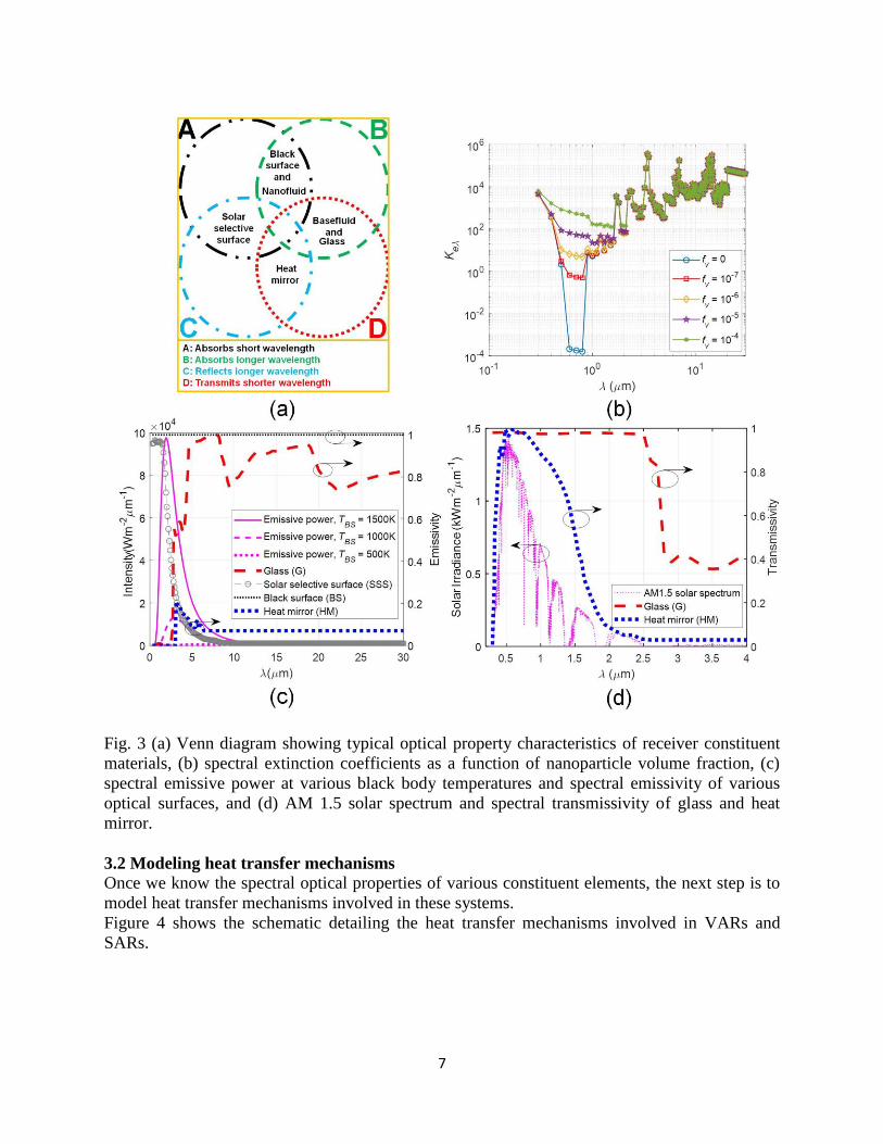
3. Theoretical modeling framework 3.1 Spectral optical properties of constituent elements Venn diagram detailing broad optical characteristics of constituent optical elements' viz.,
nanofluid, solar selective surface, black surface, basefluid, heat mirror, and glass is shown in Fig.
3(a). Optical elements could be broadly categorized into 'enveloping surfaces' and 'solar energy
absorbing elements' as described below.
3.1.1 Enveloping surfaces (glass and heat mirror): Enveloping surfaces, whether for VARs or
SARs should be highly transparent to the incident sunlight (short wavelength radiations) so that
maximum amount of sunlight is able to reach the absorbing medium/surface [see Fig. 3(d)].
Further, these have inherently high absorptivity (glass) or reflectivity (heat mirror) values in the
long wavelength infrared region [see Fig. 3(c)]. This lends them to be effective in mitigating
thermal losses. The spectral transmissivity values for glass have been calculated (detailed in
appendix A) utilizing data from Ref. [41]. The transmissivity values for heat mirrors have been
taken from Ref. [13].

6
One can see that both glass and heat mirror have high transmissivity values at short wavelengths.
However, at wavelength beyond 1µm (the cut-off wavelength in the present case), the
transmissivity of heat mirror falls rapidly. This leads to a considerably lesser solar weighted
transmissivity (defined by Eq. 1) for heat mirrors (τsw
= 0.872) than for glass (τsw
= 0.978);
allowing more solar radiation to pass through in systems with a glass cover. However, the
reduction in transmissivity values results due to corresponding increase in reflectivity. Therefore,
trade-offs need to be made at different receiver operating temperatures (by tuning the value of
cut-off wavelength) to ensure optimum performance.
30
30
0.3 0.3
30 30
0.3
0.3
m
m
m m
sw m m
m
m
S dS d
S dS d
, (1)
where Sλ
is the spectral solar irradiance (AM 1.5) and τλ is the corresponding spectral
transmissivity value of the enveloping surface (glass/heat mirror)
3.1.2 Solar energy absorbing elements (nanofluid, solar selective surface, black surface):
These are characterized by high values of extinction coefficients (calculation detailed in
appendix A)/absorptivity in the short wavelength solar irradiance region to ensure efficient
photo-thermal energy conversion. Additionally, solar selective surfaces in particular are
engineered to have low emissivity in the long wavelength infrared wavelength band to ensure
low radiative losses. However, both nanofluids and black surfaces have high emissivity in the
infrared region; therefore require enveloping surfaces [particularly heat mirrors, see Fig. 2(a) and
2(d)] to mitigate radiative losses. The emission spectra of black surface at temperatures 500K,
1000K and 1500K is also laid out in the graph showing the wavelengths at which peak emission
occurs in each instance. The peak shifts towards the left as the temperature rises [see Fig. 3(c)].
Any combination of optical elements which ensures high photo-thermal energy conversion in
conjunction with low thermal losses is suitable for solar thermal applications.
7
Fig. 3 (a) Venn diagram showing typical optical property characteristics of receiver constituent
materials, (b) spectral extinction coefficients as a function of nanoparticle volume fraction, (c)
spectral emissive power at various black body temperatures and spectral emissivity of various
optical surfaces, and (d) AM 1.5 solar spectrum and spectral transmissivity of glass and heat
mirror.
3.2 Modeling heat transfer mechanisms
Once we know the spectral optical properties of various constituent elements, the next step is to
model heat transfer mechanisms involved in these systems.
Figure 4 shows the schematic detailing the heat transfer mechanisms involved in VARs and
SARs.

8
Fig. 4 Schematic showing the heat transfer mechanisms involved in (a) VARs, and (b) SARs
The developed models are based on certain simplifying assumptions which transcends across
both VARs and SARs (described in subsection 3.2.1)). Moreover, certain aspects such as
radiation exchange between the covers are common to both VARs and SARs; and have been
described in detail in subsection 3.2.2. However, there are certain aspects which are specific to

9
the nature of absorption mechanisms and subsequent heat transfers involved (i.e., characteristics
of VARs and SARs); therefore have been treated separately in detail.
3.2.1 Underlying assumptions: Following are the modeling assumptions which are common to
both VARs and SARs:
1) The flow inside the channel is assumed to be fully developed with a parabolic velocity profile
given by Eq. (2) 2
6y av
y yu u
H H
, (2)
where
Re.
.(2 )
f
av
f
uD H
(3)
The y-component of velocity is assumed to be zero.
2) Heat transfer by conduction in the x-direction has been ignored as convection from the
moving fluid is the predominant mode of heat transfer.
3) There is nearly vacuum between the two plates, i.e., no convective heat transfer between the
bottom and the top plate.
4) Heat transfer coefficient between the casing and the atmosphere is assumed to be 10Wm-2
K-1
[42].
3.2.2 Radiation exchange between two parallel plates (the top surface of channel and the
casing that encloses it): The net heat lost by the top plate of the conduit (referred to as plate 1)
and the heat gained by the cover plate (referred to as plate 2) where one or both are semi-
transparent is explained in this section. A system of two plates with known spectral optical
properties is considered. As a result of multiple reflections taking place between the two plates,
and the fact that the radiation is spectral in nature and two-way coupling exists between the
optical behavior and plate temperatures; we need to define parameters such as effective
emissivity, absorptivity, reflectivity, and transmissivity to quantitatively determine the overall
optical characteristics of the interacting plates.
Effective emissivity: Effective emissivity [mathematically defined by Eq. (4)] is the measure of
emission from a surface relative to a corresponding black body at same temperature. It is a
material property and also a function of temperature. Figure 5 shows the effective emissivity
values as a function of temperature for glass, heat mirror and solar selective surface.
30 30 30
, , , , , , ,
0.3 0.3 0.3
30 30 30
, , , ,, ,0.3 0.30.3
1 1
m m m
b T b T T b T
m m m
eff m m m
b T b Tb Tm mm
e d e d e d
e d e de d
(4)

10
Fig. 5 Effective emissivity as a function of temperature for various optical elements, viz., solar
selective surface, glass, and heat mirror.
Effective absorptivity, reflectivity, and transmissivity: Parameters viz., effective absorptivity
[defined by Eqs. (5) and (6)]), reflectivity [defined by Eqs.(7) and (8)], and transmissivity
[defined by Eqs.(9) and (10)] are not material properties and depend on the irradiation spectra.
Since the magnitude and spectra of the radiation falling on any of the plates varies with each
reflection, these keep on changing as well.
301
,1 , , 1 ,2 ,1 ,1
0.3
1 , 301
,1 , , 1 ,2 ,1
0.3
mj j
b T
m
j eff mj j
b T
m
e d
e d
,
301 1
,1 , , 1 ,1 ,2 ,2
0.3
2 , 301 1
,1 , , 1 ,1 ,2
0.3
mj j
b T
m
j eff mj j
b T
m
e d
e d
, (5)
301 1
,2 , , 2 ,2 ,1 ,1
0.3'
1 , 301 1
,2 , , 2 ,2 ,1
0.3
mj j
b T
m
j eff mj j
b T
m
e d
e d
,
301
,2 , , 2 ,1 ,2 ,2
0.3'
2 , 301
,2 , , 2 ,1 ,2
0.3
mj j
b T
m
j eff mj j
b T
m
e d
e d
, (6)
30
,1 , , 1 ,2 ,1
0.3
1 , 301
,1 , , 1 ,2 ,1
0.3
mj j
b T
m
j eff mj j
b T
m
e d
e d
,
301
,1 , , 1 ,2 ,1
0.3
2 , 301 1
,1 , , 1 ,2 ,1
0.3
mj j
b T
m
j eff mj j
b T
m
e d
e d
, (7)

11
301
,2 , , 2 ,2 ,1
0.3'
1 , 301 1
,2 , , 2 ,2 ,1
0.3
mj j
b T
m
j eff mj j
b T
m
e d
e d
,
30
,2 , , 2 ,2 ,1
0.3'
2 , 301
,2 , , 2 ,2 ,1
0.3
mj j
b T
m
j eff mj j
b T
m
e d
e d
, (8)
301
,1 , , 1 ,2 ,1 ,1
0.3
1 , 301
,1 , , 1 ,2 ,1
0.3
mj j
b T
m
j eff mj j
b T
m
e d
e d
,
301 1
,1 , , 1 ,1 ,2 ,2
0.3
2 , 301 1
,1 , , 1 ,1 ,2
0.3
mj j
b T
m
j eff mj j
b T
m
e d
e d
, (9)
301 1
,2 , , 2 ,2 ,1 ,1
0.3'
1 , 301 1
,2 , , 2 ,2 ,1
0.3
mj j
b T
m
j eff mj j
b T
m
e d
e d
,
301
,2 , , 2 ,1 ,2 ,2
0.3'
2 , 301
,2 , , 2 ,1 ,2
0.3
mj j
b T
m
j eff mj j
b T
m
e d
e d
, (10)
where ‘j’ is the number of reflections.
Also, Eq. (11) gives the effective absorptivity of atmosphere
30
2, , , ,
0.3
3, 30
, ,
0.3
amb amb
amb
m
T b T
m
eff m
b T
m
e d
e d
(11)
Heat lost by plate 1: In case of radiation exchange between semitransparent plates (unlike
opaque surfaces), the net heat lost by one plate does not equal the net heat gained by the second
plate. Figure 5 shows the interaction of two semitransparent or one semitransparent and one
opaque plates.
4
,1 1, 1, 21, 11, 21, 22, 11, 12, 21, 22, 23, 11, 12, 13,
4 ' ' ' ' ' '
2, 2, 11, 11, 21, 12, 11, 12, 21,
[1 ...............]
[
loss eff avg eff eff eff eff eff eff eff eff eff eff eff eff
eff avg eff eff eff eff eff eff ef
Q T
T
' ' '
22, 13, ..............]f eff eff (12)
Heat gained by plate 2: The net heat gained by plate 2 is given by Eq. (13) as
4 ' ' ' ' ' ' ' ' ' ' ' '
,2 2, 2, 11, 21, 11, 12, 21, 21, 11, 12, 13, 21, 22, 23,
4
1, 1, 21, 11, 21, 22, 11, 12,
[ 1 ...............]
[
gain eff avg eff eff eff eff eff eff eff eff eff eff eff eff
eff avg eff eff eff eff eff ef
Q T
T
4
21, 22, 23, 3,]f eff eff eff eff ambT
(13)
Similarly, one can find the value of energy transmitted through to the nanofluid (Qtrans→nf
)
flowing underneath the lower plate by summing flux at points l1, m
1, n
1….and s
2, t
2, u
2, v
2 ….as
given in Fig. 6. In order to find the temperature of top cover (plate 2) when the temperature of

12
the top plate of conduit (plate 1) is known, we invoke a relationship for energy balance by
equating the energy gained by the top cover (plate 2) from the plate (plate 1) with the energy lost
by the cover (plate 2) due radiation and convection losses as given by Eq. (14)
4 4 4 ' ' ' ' ' '
2, 2, 3, 2, 2, 2, 11, 21, 11, 12, 21, 21,
4
1, 1, 21, 11, 21, 22, 11, 12, 21, 2
( ) [ 1 ...............]
[
eff avg eff amb wind avg amb eff avg eff eff eff eff eff eff
eff avg eff eff eff eff eff eff eff
T T h T T T
T
2, 23, ]eff eff
(14)
On solving Eq. (14), if the value of T1,avg
(plate 1 average temperature) is known, the value of
T2,avg
(plate 2 average temperature) can be obtained. Figure 7 unveils the relationship between
the top and bottom plate temperatures for various combinations of plate materials.

13
Fig. 6 Schematic showing radiation exchange between two parallel plates: ray tracing (and
corresponding equations) of the energy emanating from the (a) bottom (plate 1), and (b) top plate
(plate 2).

14
Fig. 7 Top plate temperature as a function of bottom plate temperature for various combinations
of plate materials.
3.2.3 Volumetric absorption based solar thermal systems: The algorithm in Fig 8 gives a brief
overview of the process of theoretical modeling pertinent to VARs.
On its way to the nanofluid, sunlight interacts with the two cover plates. The outer cover (plate
2) could be glass or heat mirror; whereas the plate in contact with the nanofluid is essentially
glass (plate 1). The heat gain by plate 2 due to radiation exchange with plate 1 and the heat loss
to the atmosphere (via convection and radiation) represents the overall energy balance for plate 2
and is given by Eq. (14). However, for plate 1; in addition to heat loss due to radiation exchange
with plate 2, it is also in thermal contact with the nanofluid (i.e. conjugate heat transfer exists
between plate 1 and nanofluid). Equations (15) – (18) describe the governing, initial and
boundary conditions for the plate 1. It may be noted that the term Qloss, 1
is based on the
temperatures of the two cover plates; which in turn requires solving Eq. (15) subject to initial and
boundary conditions [Eqs. (16) – (18)]. Further, in order to solve Eq. (18), we need to solve RTE
and the overall energy equations for the nanofluid.
,1 1
2( ),11
22
1 1 1 1 1 1
1 11 aK H t yloss
p p p
QkT TS e d
t D c y D c y D c y
(15)
0( ) ambt
T y T (16)
12 ,1lossy H t
Q S d Q
(17)

15
,1 1
[ ]
[ ]
( )1( )
1 1
1
[ ]
0
1
where 2
a
b Ty H
b T y Hy H
K t
Hy Hp
b T
k TQ e q q d
D c y
q I d
(18)
Within the nanofluid, the sunlight interacts primarily with nanoparticles through absorption and
scattering mechanisms. In these processes, both the radiative (manifested in the form of emission
and scattering phenomena) as well as non-radiative (manifested in the form of absorption
phenomena) decay of incident sunlight takes place. The RTE provides the value of radiation
intensity along the line of sight by accounting for the aforementioned three processes viz.,
absorption, emission and scattering. A numerical method for solving the RTE has been used to
calculate the value of intensity at various points in the positive and negative directions. Once the
values of intensity in the positive and negative directions are known across the fluid depth, one
can calculate the value of the net heat flux leaving a control volume (and hence the divergence of
radiative flux). The details of the discretization strategy along with procedure for solving RTE
are provided in appendices B and C respectively.
Once RTE has been solved for initial temperature distribution and the value of divergence is
known ‘a priori’, one can substitute this value of divergence into the energy equation as energy
generation term and establish the values of temperature field at new time instant. Explicit form of
finite difference formulation has been used to numerically solve the energy equation. With the
solving of the energy equation, a new temperature distribution is obtained for the next time
instant. Once again, radiation exchange between the plates (as detailed in subsection 3.2.2) and
the RTE is solved and new values of divergence are calculated for input to the energy equation.
This process gives a transient temperature distribution at different time intervals and it is
repeated until steady state has been reached.
Equations (19) – (22) represent the governing, initial and boundary conditions for the nanofluid.
2
,
2
, , ,
1 1nf rad nf trans nf
y
nf p nf nf p nf nf p nf
k Q QT T Tu
t D c y D c y D c y x
(19)
0( ) ambt
T y T (20)
[ ]
nf
y Hy Hnf pnf
k TQ q d
D c y
(21)
3 [ 0]0 yyQ q d
(22)

16
Fig. 8 Algorithm to calculate the performance parameters in relation to VARs.
3.2.4 Surface absorption based solar thermal systems: Herein, the sunlight first interacts with
the outer cover plate (plate 2, glass/heat mirror) and is subsequently absorbed by the plate 1
which happens to be a solar selective/black surface. This absorbed energy is then transferred to
the fluid through conduction and convection. Radiation exchange between the two cover plates
(one semi-transparent and one opaque in case of SAR) could be handled in a manner similar to
that for VAR. The governing equation (and initial and boundary conditions) pertinent to the heat
transfer processes in plate 1 and 2 are given by Eqs. (23) – (26) and Eq. (14) respectively.
17
2 22 11
2 2
1 1 1 1p p
S dkT T T
t D c x y D c
(23)
0( ) ambt
T y T (24)
12 ,1lossy H t
Q S d Q
(25)
1
1 1y H
p
k TQ
D c y
(26)
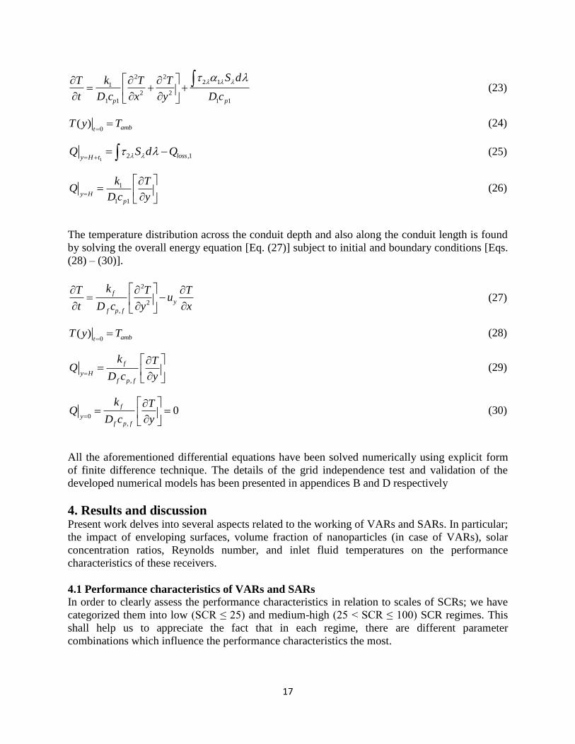
The temperature distribution across the conduit depth and also along the conduit length is found
by solving the overall energy equation [Eq. (27)] subject to initial and boundary conditions [Eqs.
(28) – (30)].
2
2
,
f
y
f p f
kT T Tu
t D c y x
(27)
0( ) ambt
T y T (28)
,
f
y Hf p f
k TQ
D c y
(29)
0,
0f
yf p f
k TQ
D c y
(30)
All the aforementioned differential equations have been solved numerically using explicit form
of finite difference technique. The details of the grid independence test and validation of the
developed numerical models has been presented in appendices B and D respectively
4. Results and discussion Present work delves into several aspects related to the working of VARs and SARs. In particular;
the impact of enveloping surfaces, volume fraction of nanoparticles (in case of VARs), solar
concentration ratios, Reynolds number, and inlet fluid temperatures on the performance
characteristics of these receivers.
4.1 Performance characteristics of VARs and SARs
In order to clearly assess the performance characteristics in relation to scales of SCRs; we have
categorized them into low (SCR ≤ 25) and medium-high (25 < SCR ≤ 100) SCR regimes. This
shall help us to appreciate the fact that in each regime, there are different parameter
combinations which influence the performance characteristics the most.

18
4.1.1 Low solar concentration ratio regime (SCR ≤ 25): In this regime we have analyzed the
impact of nanoparticles volume fraction, receiver design, Reynolds number, and inlet fluid
temperature on the performance characteristics of VARs and SARs
Effect of nanoparticles volume fraction on efficiency of VARs: Figure 9 shows surface plots for
different designs of volumetric absorption-based receivers in low SCR regime. For all the three
receiver designs, the receiver efficiency increases with volume fraction and attains a maximum
value at 10-5
(in the present case); subsequently, the efficiency steeply decreases (or remains
constant) with further increase in nanoparticles volume fraction. This happens because at very
low volume fractions, radiation remains un-captured by the absorbing medium and at very high
volume fractions, most of the radiation is captured near the surface (emulating surface
absorption) and does not percolate down to the lower fluid layers in the receiver - resulting in
low average fluid temperatures and increased thermal losses. Thus, there exists an optimum
nanoparticle volume fraction that ensures favorable energy distribution across the fluid thickness.
Moreover, in case of glass-heat mirror design, the heat mirror reflects the emitted radiation back
to the glass (and nanofluid) - resulting in lower thermal losses. Further, it may be noted that
receiver efficiency is higher at higher Reynolds number due to decrease in the emission losses.
Effect of Reynolds number has been dealt with in a greater detail in the next section.
Effect of Reynolds number on efficiency of VARs: Figure 10 gives contour plots for different
designs of volumetric absorption-based receivers at optimum volume fraction (10-5
). Optimum
receiver efficiency values are achieved at higher Reynolds number and low solar concentration
ratios. For any Reynolds number as the solar concentration ratio increases, the receiver
efficiency decreases. However, there is very little variation in receiver efficiency for the case of
glass-heat mirror design in this range of solar concentration ratios as is evident from the widely
spaced contours. This is because at conditions of low Reynolds number and high concentration
ratios, the temperatures at the top surface are high which exaggerate the emission losses.
However, the design that includes a heat mirror reflects the emitted radiation back to the receiver
thus reducing losses and therefore the receiver efficiency remains almost unaffected.

19
Fig. 9: Effect of nanoparticle volume fraction on receiver efficiency for volumetric absorption-
based receivers in low SCR regime.

20
Fig. 10: Effect of Reynolds number on receiver efficiency of Volumetric absorption-based
receiver in low SCR regime.
Effect of inlet fluid temperature on receiver, Carnot and overall efficiency of VARs:
Figure 11 compares the receiver efficiency, Carnot efficiency and overall efficiency for two
designs of volumetric absorption-based receivers (i.e. the glass-heat mirror and the glass-glass
design) at Re = 200 and 1600. While the receiver efficiency is higher for glass-glass designs at
low inlet fluid temperatures, it decreases at a more rapid rate as compared to that of glass-heat
mirror designs at higher inlet temperatures. The Carnot efficiency curves for the two designs
overlap with each other, so while the overall efficiency is higher for glass-glass design at low
inlet fluid temperatures, at higher inlet fluid temperatures the overall efficiency is greater for
glass-heat mirror design. The critical inlet fluid temperature after which the receiver efficiency
for G-H exceeds the G-G depends on solar concentration ratio and it shifts to higher values of

21
inlet fluid temperatures at higher SCR. This owes to the fact that at low inlet fluid temperatures
the emission losses are not as much as they are at higher inlet temperatures and glass-heat mirror
design reflects the emitted radiation back to the receiver.
Fig. 11 Comparison of receiver, Carnot and overall efficiencies at different inlet fluid
temperatures in case of VARs (a) SCR = 5, Re = 200 (b) SCR = 25, Re = 200 (c) SCR = 5, Re =
1600, and (d) SCR = 25, Re = 1600
Effect of Reynolds number on efficiency of SARs: Figure 12 gives contour plots for different
designs of surface-absorption based receivers in low SCR regime. Just as was the case for
volumetric-absorption receivers, optimum receiver efficiency values are attained at low solar
concentration ratios and high Reynolds Number. However, the change in efficiency for the case
of surface absorption-based receivers is much steeper than its volumetric absorption-based

22
receiver counterparts as can be seen from the density of the contours which are much far apart in
the latter case. This is because the top surface attains much higher temperature than the fluid
owing to a thermal barrier created between the two thus making surface absorption-based
receiver much more sensitive to changes in the solar concentration ratio.
Fig. 12: Effect of Reynolds number on receiver efficiency of surface absorption-based receiver in
low SCR regime.
Effect of inlet fluid temperature on receiver, Carnot and overall efficiency of SARs: Figure 13
compares the receiver efficiency, Carnot efficiency and overall efficiency for two designs of
surface absorption-based receivers (i.e. the black surface-heat mirror and the solar selective
surface-glass design) in low SCR regime at Re = 200 and 1600. While the receiver efficiency is
higher for solar selective surface-glass designs at low inlet temperatures, it decreases at a more
rapid rate as compared to that of black surface-heat mirror designs at higher inlet temperatures.
However at high solar concentration ratios, this difference is not very appreciable and receiver
efficiencies remain almost the same for both the cases. The Carnot efficiency curves for the two

23
designs overlap with each other. In the temperature range considered in the present study, the
receiver efficiencies for black surface-heat mirror are always lower than those of solar selective
surface-glass design. The receiver efficiencies are lower for the case of BS-HM design because
of the lower amount of incident radiation that is allowed to pass through to the receiver. Also due
to the presence of a solar selective surface in the SSS-G design, the radiation emitted by a solar
selective surface is much lower than it is for a black surface in the BS-HM design.
Fig. 13 Comparison of receiver, Carnot and overall efficiencies at different inlet fluid
temperatures in case of SARs (a) SCR = 5, Re = 200 (b) SCR = 25, Re = 200 (c) SCR = 5, Re =
1600, and (d) SCR = 25, Re = 1600

24
4.1.2 Medium-high solar concentration ratio regime (25 < SCR ≤ 100): In this regime, we have
analyzed the impact of inlet fluid temperature, receiver design, and Reynolds number on the
performance characteristics of VARs and SARs.
Effect of inlet fluid temperature and Reynolds number on receiver, Carnot and overall efficiency
of VARs: Figure 14 compares the receiver efficiency, Carnot efficiency and overall efficiency for
two designs of volumetric absorption-based receivers (i.e. the glass-heat mirror and the glass-
glass design) at Re = 200 and 1600. The receiver efficiencies do not vary much (although slightly
decrease in all the cases) with increase in inlet fluid temperatures. This may be attributed to the
fact that at high SCRs, the relative magnitude of useful thermal energy gain outpowers the
thermal energy losses – thus limiting the efficiency decrease with increase in inlet fluid
temperatures. However, similar to the trennds in low SCR regime; the Carnot efficiency curves
for the two designs overlap with each other.
Further, while the overall efficiency is higher for glass-glass design across the entire inlet fluid
temperatures range; at still higher inlet fluid temperatures the overall efficiency is greater for
glass-heat mirror design. Moreover, the critical inlet temperature where the receiver efficiency
for G-H starts to overtake the G-G case shifts to much higher inlet fluid temperatures (~ 600K).
Clearly pointing out that the critical point shifts towards right with increase in SCR.

25
Fig. 14 Comparison of receiver, Carnot and overall efficiencies at different inlet fluid
temperatures in case of VARs (a) SCR = 50, Re = 200 (b) SCR = 100, Re = 200 (c) SCR = 50,
Re = 1600, and (d) SCR = 100, Re = 1600
Effect of inlet fluid temperature and Reynolds number on receiver, Carnot and overall Efficiency
of SARs: Figure 15 compares the receiver efficiency, Carnot efficiency and overall efficiency for
two designs of surface absorption-based receivers (i.e. the black surface-heat mirror and the solar
selective surface-glass design) at Re = 200 and 1600. At low Reynolds number (Re = 200), the
efficiecies are considerably low even at low inlet fluid temperatures. Moreover, efficiencies
further decrease with increase in inlet fluid temperatures and SCR. This can attributed to the fact
that at low Reynolds numbers and high SCRs, staggering amount of thermal energy gets
accumulated at the surface – owing to low Reynolds number, the fluid is unable to take this
energy with it, therefore resulting in huge temperature overheat (i.e., surface temperatures are

26
significanly higher than the fluid temperatures). This further leads to escalation of thermal losses.
Simillar trends could be seen at high Reynolds number as well; however, the magnitude of
temperature overheat and subsequent emission losses being dimnished in comparison to the low
Reynolds number case.
Fig. 15 Comparison of receiver, Carnot and overall efficiencies at different inlet fluid
temperatures in case of SARs (a) SCR = 50, Re = 200 (b) SCR = 100, Re = 200 (c) SCR = 50, Re
= 1600, and (d) SCR = 100, Re = 1600
4.2 Delineating optimal range of operating and design parameters for VARs and SARs:
The big picture

27
Figure 16 shows how receiver, Carnot and overall efficiencies compare between volumetric and
surface absorption based receivers. It is seen that as the solar concentration ratios increase, the
receiver efficiencies drop rapidly for surface absorption-based receivers (both for Tin
= 293K and
593K). Whereas, in case of VARs, we have two distinct trends: while efficiencies decrease
slightly or remain almost constant) at low inlet fluid temperatures (Tin
= 293K); at high inlet fluid
temperatures (Tin
= 593K), efficiencies first increase and then stagnate with increase in SCR.
Fig. 16 Difference in efficiencies between volumetric and surface absorption based receivers (a)
receiver efficiency, Tin = 293K, and (b) receiver efficiency, Tin = 593K.
In order to clearly understand the heat transfer mechanisms involved in VARs and SARs, we
have plotted the exit temperature field for these at different Reynolds number and inlet fluid
temperatures. Figure 17 compares the exit temperature field plots for black surface-heat mirror
design (surface absorption-based receiver) with those of glass-heat mirror design (volumetric
absorption-based receiver). Particularly, G-HM and BS-HM cases have been considered as these
are similar in all aspects except for the mechanisms of heat transfer involved. One can see that
the maximum temperature for the case of SAR design is at the surface and there is a very steep
difference in temperature between the surface and the topmost layer of the fluid (i.e. significant
overheat temperature exists). On the contrary, the temperature of the top glass plate for the case
of VAR design is lower than the temperature of topmost layer of fluid in the conduit (i.e., there
exists a temperature inversion in case of VARs) which leads to lower emission losses and better
distribution of energy across the fluid layers – resulting in higher efficiencies for volumetric
absorption-based receivers.

28
Fig. 17: Comparison of exit temperature distribution between volumetric and surface absorption
based receivers (a) Re = 200, Tin
= 293K (b) Re = 200, Tin
= 593K (c) Re = 1600, Tin
= 293K, and
(d) Re = 200, Tin
= 593K.
Therefore, the absence of temperature overheat and instead existance of temperature inversion in
case of VARs lends them to be more suitable (particularly in medium-high SCRs regime) as
compared to corresponding SARs. Receiver efficiency enhancements on the order of ~35% @Re
= 1600 to 49% @ Re = 200 could be achieved in case of VARs relative to their SAR
counterparts at SCR = 100.
29
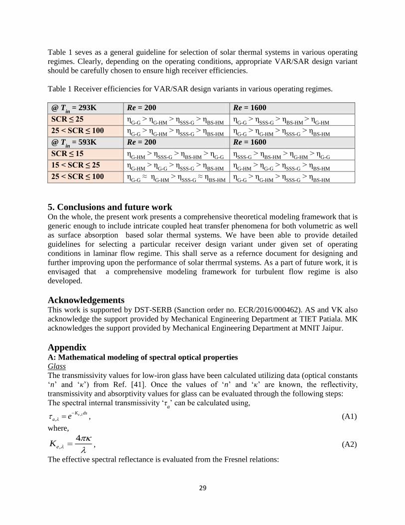
Table 1 seves as a general guideline for selection of solar thermal systems in various operating
regimes. Clearly, depending on the operating conditions, appropriate VAR/SAR design variant
should be carefully chosen to ensure high receiver efficiencies.
Table 1 Receiver efficiencies for VAR/SAR design variants in various operating regimes.
@ Tin
= 293K Re = 200 Re = 1600
SCR ≤ 25 ηG-G
> ηG-HM
> ηSSS-G
> ηBS-HM
ηG-G
> ηSSS-G
> ηBS-HM
> ηG-HM
25 < SCR ≤ 100 ηG-G
> ηG-HM
> ηSSS-G
> ηBS-HM
ηG-G
> ηG-HM
> ηSSS-G
> ηBS-HM
@ Tin
= 593K Re = 200 Re = 1600
SCR ≤ 15 ηG-HM
> ηSSS-G
> ηBS-HM
> ηG-G
ηSSS-G
> ηBS-HM
> ηG-HM
> ηG-G
15 < SCR ≤ 25 ηG-HM
> ηG-G
> ηSSS-G
> ηBS-HM
ηG-HM
> ηG-G
> ηSSS-G
> ηBS-HM
25 < SCR ≤ 100 ηG-G
≈ ηG-HM
> ηSSS-G
≈ ηBS-HM
ηG-G
> ηG-HM
> ηSSS-G
> ηBS-HM
5. Conclusions and future work On the whole, the present work presents a comprehensive theoretical modeling framework that is
generic enough to include intricate coupled heat transfer phenomena for both volumetric as well
as surface absorption based solar thermal systems. We have been able to provide detailed
guidelines for selecting a particular receiver design variant under given set of operating
conditions in laminar flow regime. This shall serve as a refernce document for designing and
further improving upon the performance of solar therrmal systems. As a part of future work, it is
envisaged that a comprehensive modeling framework for turbulent flow regime is also
developed.
Acknowledgements This work is supported by DST-SERB (Sanction order no. ECR/2016/000462). AS and VK also
acknowledge the support provided by Mechanical Engineering Department at TIET Patiala. MK
acknowledges the support provided by Mechanical Engineering Department at MNIT Jaipur.
Appendix A: Mathematical modeling of spectral optical properties
Glass
The transmissivity values for low-iron glass have been calculated utilizing data (optical constants
‘n’ and ‘κ’) from Ref. [41]. Once the values of ‘n’ and ‘κ’ are known, the reflectivity,
transmissivity and absorptivity values for glass can be evaluated through the following steps:
The spectral internal transmissivity ‘τa’ can be calculated using,
,
,eK ds
a e
, (A1)
where,
,
4eK
, (A2)
The effective spectral reflectance is evaluated from the Fresnel relations:

30
2 2
, 2 2
2 22 2
, , , ,
, 2 22 2
, , , ,
, ,
,
( cos )
( cos )
( )cos 2 cos
( )cos 2 cos
2
vac
vac
h h vac h h vac
h h vac h h vac
avg
n w v
n w v
n n w n n
n n w n n
, (A3)
where,
22 2 2 2 2 2 2 2 2 2 2
, , , , , ,
22 2 2 2 2 2 2 2 2 2 2
, , , , , ,
2 sin sin 4
2 sin sin 4
h h vac h h vac h h
h h vac h h vac h h
w n n n n n
v n n n n n
, (A4)
The spectral absorptivity for glass is then calculated from
, ,1 a avga , (A5)
The values calculated were scaled such that the solar weighted transmissivity of glass is 97.8%.
Nanofluid
As radiation propagates through the nanofluid; its magnitude changes owing to absorption and
scattering mechanisms. Attenuation of radiation due to scattering is negligibly small as the
particles are much smaller than the wavelength of incident light which means that scattering
occurs in the Rayleigh regime and absorption dominates [29]. Absorption and scattering
mechanisms could be quantified using the following expressions:
, ,
4a bfK
, (A6)
where ‘Ka,λ
’ is the spectral absorption coefficient, ‘κ’ is the spectral index of absorption, and ‘λ’
is the wavelength.
The combined attenuation from absorption and scattering by nanoparticles is taken care of by
extinction coefficient, given as,
,
, ,
1.5 ( , )v e
e np
f Q mK
d
, (A7)
where, ‘Ke,λ
’ is the spectral extinction coefficient, ‘fv’ is the volume fraction, ‘d’ is the
characteristic dimension (hydrodynamic diameter, d = 1nm), ‘β’ is the size parameter, ‘m’ is the
normalized refractive index and ‘Qe,λ
’ is the extinction efficiency of the particles defined as
follows [22]:
d
, (A8)

31
np
bf
mm
n , (A9)
22 2 2 4 2 2
4
, 2 2 2 2
1 1 27 38 8 14 Im 1 Re
2 15 2 2 3 3 2e
m m m m mQ
m m m m
, (A10)
The values of ‘κ’ for base-fluid were obtained from Ref. [43]. The ‘n’ and ‘κ’ values for
nanoparticles have been taken from Ref. [44, 45].
Once we have calculated the value of extinction coefficients for base-fluid and nanoparticles
individually, we can find the value of extinction coefficient for the nanofluid simply by adding
the two.
, , , , , ,e nf a bf e npK K K , (A11)
B: Numerical modeling
Plate 1 (solar selective/black/glass) and the fluid (basefluid/nanofluid) have been discretized into
finite control volumes. Explicit form of finite difference technique has been employed to convert
the integro-differential equations into set of algebraic equations – characteristic algebraic
equations for interior and boundary nodes. Figure B1 show the discretization strategy followed
for numerical modeling VARs in particular. RTE is essentially solved in y-z plane; whereas, the
overall energy balance equation is solved in x-y plane until steady state is reached.
Fig. B1 Discretization strategy for numerical modeling of VARs.

32
Further, It may be noted that grid independence test was carried out and it was found that the
results were nearly independent of grid size beyond 49×700 (see Fig. B2).
Fig. B2 Spatial temperature distribution along the conduit length at y/H = 6/7 for various grid
sizes.
C: Solution of the radiative transfer equation (RTE)
Figure C1 shows the y-z plane of the conduit. The nanofluid is bounded by glass and reflective
plates at the top and bottom respectively. To find the values of radiation intensity in positive and
negative directions at various points along the depth of the channel the RTE has been solved
numerically. Once intensity at different depths in different directions (+ve and -ve) is known, the
‘divergence’ which is the net radiative energy per unit time and volume leaving a differential
control volume into which the channel depth has been subdivided can be found.
Fig. C1 Schematic showing the y-z plane defining the +ve and -ve directions of Φ and the heat
flux,

33
From the boundary conditions we get Eqs. (C1) and (C2).
( , ) 1 1 1 ( , ) 1 [ ]. . .H H b y HI S I I
(C1)
(0, ) 3 (0, ).I I
(C2)
We get two more equations from the equation of radiative transfer for an absorbing, emitting
non-scattering medium [Eqs. (C3) and (C4)]
( ')
( , ) (0, )
0
exp '
HH
bHH
II I e d
(C3)
'0
( ')
(0, ) ( , ) exp '
H
H
bHH
II I e d
(C4)
Radiation travelling from the top cover to the bottom is regarded as +ve and vice versa.
Solving Eqs. (C1) - (C4), we get Eqs. C5 and C6
[ ]
''0
( ') ( ')
1 1 1 1 3 1
0
( , )
1 3
. . . .exp . .e ' . .e '
21 . .exp
0
HH
y H
H
b bHb T
H
H
I IS I d d
I
for
(C5)
''0
( ') ( ')
3 1 1 1 3 [ ] 1 3 3
0
(0, )
1 3
. . .exp . . .exp . .exp . .e ' . .e '
21 . .exp
0
HH
H
b bH H Hb y H
H
I IS I d d
I
for
(C6)
The hemispherical flux at any location is obtained by integrating the intensity field.
1
0
0
1
2
2
q I d
q I d
(C7)
Once the values of intensity at the boundaries are calculated, one can use Eq. (C8) to find the
intensity and thus hemispherical flux at any point in between the two plates.
10
' '( ) exp ( ').exp
t
b
dI I I
(C8)

34
The spectral intensity of radiation emitted locally inside a medium is given by Eq. (C9)
2
3
1, /5 1
b C T
C nI
e
(C9)
where, C1=3.74177×10
8 and C
2=3.74177×10
8, ‘n’ is the refractive index, ‘λ’ is wavelength and
‘T’ is for temperature (Howell).
The divergence for any generic volume element is given by Eq. (C10) as
, , ,rad nf net out net inQ q q (C10)
The divergence thus calculated can be included in the energy equation to find the temperature
distribution within the nanofluid.
D: Validation of numerical models
RTE model validation
Two infinite black walls at a distance ‘H’ are considered. The known conditions are the
temperatures (T1 and T
2) and emissivities (ε
1= ε
2=1) of the two walls, and the absorption
coefficients (Ka) of the intervening medium. The non-dimensional blackbody flux at any optical
thickness ‘t’ (where t = Ka y, y being the distance from wall 1) is given by Eq. (D1) as
* 2
1 2
( )( ) b b
b
b b
e t ee t
e e
(D1)
The value of eb
* at the temperature of wall 1 is e
b
*(T
1) =1 and the value of e
b
* at the temperature
of wall 2 is eb
*(T
2) = 0. Figure D1 shows the comparison between present developed model and
that in Ref. [46]; clearly the two closely match for various values of absorption coefficients.

35
Fig. D1 Non-dimensional temperature profile for a gray slab in radiative equilibrium for different
values of optical thickness - comparison of results of present work with those in Ref. [46].
Validation of numerical model for SARs
In order to validate the numerical model developed for SARs, the results obtained from the
numerical model were compared with those obtained from ANSYS®. A channel length of 4
meters and width of 5cm has been considered with a black surface at the top. Solar radiation
(1000Wm-2
) falls on the top surface of the channel absorbing all radiation and heating up, thus in
turn heating the fluid flowing through the channel. The initial temperature of the fluid and the
ambient temperatures are both assumed to be 293K. Temperature distribution was obtained for
both cases. Figure D2 shows a comparison of temperature distribution of both cases along the
channel length at various channel heights. Both the results are in agreement with each other thus
validating the numerical approach for finding the temperature distribution in a surface
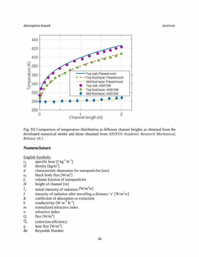
36
absorption-based receiver.
Fig. D2 Comparison of temperature distribution at different channel heights as obtained from the
developed numerical model and those obtained from ANSYS® Academic Research Mechanical,
Release 18.1.
Nomenclature
English Symbols:
cp specific heat [J kg-1
K-1
]
D density [kg/m3]
d characteristic dimension for nanoparticles [nm]
eb black body flux [W/m2]
fv volume fraction of nanoparticles
H height of channel [m]
Io initial intensity of radiation [W/m
2sr]
I intensity of radiation after travelling a distance ‘s’ [W/m2sr]
K coefficient of absorption or extinction
k conductivity [W m-1
K-1
]
m normalized refractive index
n refractive index
Q flux [W/m2]
Qe extinction efficiency
q heat flux [W/m2]
Re Reynolds Number

37
S solar irradiance [W/m2]
s distance travelled by radiation [m]
T temperature [K]
t time[sec]
t1 thickness of the top plate of the channel
u velocity in x-direction [m/sec]
y position along channel depth [m]
Greek Symbols:
α absorptivity
β size parameter
ε emissivity
κ optical constant
λ wavelength
ϕ cosine of direction in which radiation is travelling
ρ reflectivity
θ optical depth
τ transmissivity
μ dynamic viscosity [kg m-1
s-1
]
ψ angle of incidence
Subscript:
a absorption
amb ambient
avg average
b black body
e extinction
eff effective
f basefluid
in inlet temperature
loss loss
nf nanofluid
np nanoparticle
sw solar weighted
vac vacuum
y position along channel depth
1 top plate of the channel
2 casing
3 bottom plate of the channel
λ spectral
perpendicular
parallel
Superscript:
j number of reflections
+ direction of propagation from top to bottom

38
- direction of propagation from bottom to top
Abbreviations and acronyms:
SAR Surface absorption-based receiver
VAR Volumetric absorption-based receiver
BS-HM Black surface-heat mirror receiver design
G-A Glass-atmosphere receiver design
G-G Glass-glass receiver design
G-HM Glass-heat mirror receiver design
SSS-ATM Solar selective surface-atmosphere receiver design
SSS-G Solar selective surface-glass receiver design
References
[1] Total primary energy supply (TPES) by source, World 1990-2017, World Energy Balances
2019, IEA. https://www.iea.org/statistics/ (accessed on11th
November 2019).
[2] Blanco, J., Malato, S., Fernández-Ibañez, P., Alarcón, D., Gernjak, W. and Maldonado, M.I.,
2009. Review of feasible solar energy applications to water processes. Renewable and
Sustainable Energy Reviews, 13(6-7), pp.1437-1445.
[3] Electricity generation by source, World 1990-2017, Electricity Information 2019, IEA.
https://webstore.iea.org/electricity-information-2019 (accessed on11th
November 2019).
[4] Lenert, A., 2010. Nanofluid-based receivers for high-temperature, high-flux direct solar
collectors (Masters dissertation, Massachusetts Institute of Technology).
[5] Lenert, A. and Wang, E.N., 2012. Optimization of nanofluid volumetric receivers for solar
thermal energy conversion. Solar Energy, 86(1), pp.253-265.
[6] Otanicar, T.P., Phelan, P.E., Prasher, R.S., Rosengarten, G. and Taylor, R.A., 2010.
Nanofluid-based direct absorption solar collector. Journal of renewable and sustainable
energy, 2(3), p.033102.
[7] Taylor, R.A., Phelan, P.E., Otanicar, T.P., Walker, C.A., Nguyen, M., Trimble, S. and
Prasher, R., 2011. Applicability of nanofluids in high flux solar collectors. Journal of Renewable
and Sustainable Energy, 3(2), p.023104.
[8] Khullar, V., Tyagi, H., Hordy, N., Otanicar, T.P., Hewakuruppu, Y., Modi, P. and Taylor,
R.A., 2014. Harvesting solar thermal energy through nanofluid-based volumetric absorption
systems. International Journal of Heat and Mass Transfer, 77, pp.377-384.
[9] Bortolato, M., Dugaria, S., Agresti, F., Barison, S., Fedele, L., Sani, E. and Del Col, D., 2017.
Investigation of a single wall carbon nanohorn-based nanofluid in a full-scale direct absorption
parabolic trough solar collector. Energy conversion and management, 150, pp.693-703.
[10] Veeraragavan, A., Lenert, A., Yilbas, B., Al-Dini, S. and Wang, E.N., 2012. Analytical
model for the design of volumetric solar flow receivers. International Journal of Heat and Mass
Transfer, 55(4), pp.556-564.
[11] Hewakuruppu, Y.L., Taylor, R.A., Tyagi, H., Khullar, V., Otanicar, T., Coulombe, S. and
Hordy, N., 2015. Limits of selectivity of direct volumetric solar absorption. Solar Energy, 114,
pp.206-216.
[12] Li, Q., Zheng, C., Mesgari, S., Hewkuruppu, Y.L., Hjerrild, N., Crisostomo, F.,
Rosengarten, G., Scott, J.A. and Taylor, R.A., 2016. Experimental and numerical investigation of
volumetric versus surface solar absorbers for a concentrated solar thermal collector. Solar
Energy, 136, pp.349-364.

39
[13] Khullar, V., Tyagi, H., Otanicar, T.P., Hewakuruppu, Y.L. and Taylor, R.A., 2018. Solar
selective volumetric receivers for harnessing solar thermal energy. Journal of Heat
Transfer, 140(6), p.062702.
[14] Chen, M., He, Y., Zhu, J. and Wen, D., 2016. Investigating the collector efficiency of silver
nanofluids based direct absorption solar collectors. Applied energy, 181, pp.65-74.
[15] Sharaf, O.Z., Al-Khateeb, A.N., Kyritsis, D.C. and Abu-Nada, E., 2018. Direct absorption
solar collector (DASC) modeling and simulation using a novel Eulerian-Lagrangian hybrid
approach: Optical, thermal, and hydrodynamic interactions. Applied energy, 231, pp.1132-1145.
[16] Khullar, V., Bhalla, V. and Tyagi, H., 2018. Potential heat transfer fluids (nanofluids) for
direct volumetric absorption-based solar thermal systems. Journal of Thermal Science and
Engineering Applications, 10(1), p.011009.
[17] Mehrali, M., Ghatkesar, M.K. and Pecnik, R., 2018. Full-spectrum volumetric solar thermal
conversion via graphene/silver hybrid plasmonic nanofluids. Applied energy, 224, pp.103-115.
[18] Hordy, N., Rabilloud, D., Meunier, J.L. and Coulombe, S., 2015. A stable carbon nanotube
nanofluid for latent heat-driven volumetric absorption solar heating applications. Journal of
Nanomaterials, 16(1), p.248.
[19] Chen, Y., Quan, X., Wang, Z., Lee, C., Wang, Z., Tao, P., Song, C., Wu, J., Shang, W. and
Deng, T., 2016. Stably dispersed high-temperature Fe 3 O 4/silicone-oil nanofluids for direct
solar thermal energy harvesting. Journal of Materials Chemistry A, 4(44), pp.17503-17511.
[20] Mesgari, S., Taylor, R.A., Hjerrild, N.E., Crisostomo, F., Li, Q. and Scott, J., 2016. An
investigation of thermal stability of carbon nanofluids for solar thermal applications. Solar
Energy Materials and Solar Cells, 157, pp.652-659.
[21] Singh, N. and Khullar, V., 2019. Efficient Volumetric Absorption Solar Thermal Platforms
Employing Thermally Stable-Solar Selective Nanofluids Engineered from Used Engine
Oil. Scientific reports, 9(1), pp.1-12.
[22] Tyagi, H., Phelan, P. and Prasher, R., 2009. Predicted efficiency of a low-temperature
nanofluid-based direct absorption solar collector. Journal of solar energy engineering, 131(4),
p.041004.
[23] Khullar, V., Tyagi, H., Phelan, P.E., Otanicar, T.P., Singh, H. and Taylor, R.A., 2012. Solar
energy harvesting using nanofluids-based concentrating solar collector. Journal of
Nanotechnology in Engineering and Medicine, 3(3), p.031003.
[24] Ebrahimnia-Bajestan, E., Moghadam, M.C., Niazmand, H., Daungthongsuk, W. and
Wongwises, S., 2016. Experimental and numerical investigation of nanofluids heat transfer
characteristics for application in solar heat exchangers. International Journal of Heat and Mass
Transfer, 92, pp.1041-1052.
[25] Sharaf, O.Z., Kyritsis, D.C. and Abu-Nada, E., 2018. Impact of nanofluids, radiation
spectrum, and hydrodynamics on the performance of direct absorption solar collectors. Energy
conversion and management, 156, pp.706-722.
[26] Sharaf, O.Z., Kyritsis, D.C., Al-Khateeb, A.N. and Abu-Nada, E., 2018. Effect of bottom
surface optical boundary conditions on nanofluid-based DASC: Parametric study and
optimization. Solar Energy, 164, pp.210-223.
[27] Fan, M., Liang, H., You, S., Zhang, H., Zheng, W. and Xia, J., 2018. Heat transfer analysis
of a new volumetric based receiver for parabolic trough solar collector. Energy, 142, pp.920-931.
[28] O’Keeffe, G.J., Mitchell, S.L., Myers, T.G. and Cregan, V., 2018. Modelling the efficiency
of a nanofluid-based direct absorption parabolic trough solar collector. Solar Energy, 159, pp.44-
54.

40
[29] Freedman, J.P., Wang, H. and Prasher, R.S., 2018. Analysis of nanofluid-based parabolic
trough collectors for solar thermal applications. Journal of Solar Energy Engineering, 140(5),
p.051008.
[30] Gorji, T.B. and Ranjbar, A.A., 2016. A numerical and experimental investigation on the
performance of a low-flux direct absorption solar collector (DASC) using graphite, magnetite
and silver nanofluids. Solar Energy, 135, pp.493-505.
[31] Cregan, V. and Myers, T.G., 2015. Modelling the efficiency of a nanofluid direct absorption
solar collector. International Journal of Heat and Mass Transfer, 90, pp.505-514.
[32] Saidur, R., Meng, T.C., Said, Z., Hasanuzzaman, M. and Kamyar, A., 2012. Evaluation of
the effect of nanofluid-based absorbers on direct solar collector. International Journal of Heat
and Mass Transfer, 55(21-22), pp.5899-5907.
[33] Minea, A.A. and El-Maghlany, W.M., 2018. Influence of hybrid nanofluids on the
performance of parabolic trough collectors in solar thermal systems: recent findings and
numerical comparison. Renewable energy, 120, pp.350-364.
[34] Bonab, H.B. and Javani, N., 2019. Investigation and optimization of solar volumetric
absorption systems using nanoparticles. Solar Energy Materials and Solar Cells, 194, pp.229-
234.
[35] Ladjevardi, S.M., Asnaghi, A., Izadkhast, P.S. and Kashani, A.H., 2013. Applicability of
graphite nanofluids in direct solar energy absorption. Solar Energy, 94, pp.327-334.
[36] Lee, S.H., Choi, T.J. and Jang, S.P., 2016. Thermal efficiency comparison: Surface-based
solar receivers with conventional fluids and volumetric solar receivers with
nanofluids. Energy, 115, pp.404-417.
[37] Amjad, M., Raza, G., Xin, Y., Pervaiz, S., Xu, J., Du, X. and Wen, D., 2017. Volumetric
solar heating and steam generation via gold nanofluids. Applied energy, 206, pp.393-400.
[38] Mallah, A.R., Kazi, S.N., Zubir, M.N.M. and Badarudin, A., 2018. Blended morphologies
of plasmonic nanofluids for direct absorption applications. Applied energy, 229, pp.505-521.
[39] Sönnichsen, C., Franzl, T., Wilk, T., von Plessen, G., Feldmann, J., Wilson, O.V. and
Mulvaney, P., 2002. Drastic reduction of plasmon damping in gold nanorods. Physical review
letters, 88(7), p.077402.
[40] Khullar, V., Mahendra, P. and Mittal, M., 2018. Applicability of heat mirrors in reducing
thermal losses in concentrating solar collectors. Journal of Thermal Science and Engineering
Applications, 10(6), p.061004.
[41] Rubin, M., 1985. Optical properties of soda lime silica glasses. Solar energy
materials, 12(4), pp.275-288.
[42] Duffie, J.A. and Beckman, W.A., 2013. Solar engineering of thermal processes. John Wiley
& Sons.
[43] Hewakuruppu, Y. L., 2016. Investigating the potential of developing a selective nanofluid-
based direct absorption solar collector (Doctoral dissertation, UNSW).
[44] Maron, N., 1990. Optical properties of fine amorphous carbon grains in the infrared
region. Astrophysics and Space Science, 172(1), pp.21-28.
[45] Stagg, B.J. and Charalampopoulos, T.T., 1993. Refractive indices of pyrolytic graphite,
amorphous carbon, and flame soot in the temperature range 25 to 600 C. Combustion and
flame, 94(4), pp.381-396.
[46] Heaslet, M.A. and Warming, R.F., 1965. Radiative transport and wall temperature slip in an
absorbing planar medium. International Journal of Heat and Mass Transfer, 8(7), pp.979-994.