performance criteria for bridges … criteria for bridges designed with spread footings on...
TRANSCRIPT

1
PERFORMANCE CRITERIA FOR BRIDGES DESIGNED WITH SPREAD FOOTINGS ON LIQUEFIABLE SOILS
Anastasios SEXTOS1, Nikoletta PSILLA2, Ioannis PSYCHARIS3, Andreas KAPPOS4,
Olympia TASKARI5, Isabella VASSILOPOULOU6, Elli-Konstantina MYLONA7, Charis GANTES8, George BOUCKOVALAS9
ABSTRACT
The scope of this paper is to provide an overview of the concept of designing bridge piers founded on liquefaction susceptible soils using spread footings, utilizing liquefaction as natural soil isolation, and discuss the performance criteria that could be used to evaluate its feasibility, applicability and efficiency. A stepwise procedure is proposed for providing proof of the concept, involving appropriate spread foundation design, as well as seismic scenarios and free-field earthquake excitations for the dynamic analysis of the bridge. Special attention is drawn on liquefaction-induced ground movements in the form of settlements and rotations. Calculations are further back-verified for the case that the ground deformations exceed the design ones. To this end, structural performance criteria for the maximum tolerable ground deformations are provided based on the distinct modes of failure of the superstructure and the target residual capacity of the structure to withstand traffic and future seismic loads after a major earthquake event. A preliminary demonstration study is presented for three typical structural systems: a statically determinate and a statically indeterminate concrete bridge, as well as a steel overpass. The results indicate that, bridges that have been ad hoc designed to the proposed concept, the additional liquefaction-induced soil deformations are indeed tolerable.
INTRODUCTION
The common practice for bridges exposed to seismic hazard and built on soils susceptible to liquefaction is to design deep (pile) foundation systems combined with extensive improvement of the surrounding soil. Based on the current state of knowledge, deep foundations appear today to be the only adequately safe, though conservative solution, resulting to a significant increase in the project cost, compared to cases where shallow foundations could be used [FHWA (1982), FHWA (1987), Sargand and Masada (2006)).
1 Assistant Professor, Aristotle University of Thessaloniki, Greece, [email protected] 2 Dr. Civil Engineer, National Technical University of Athens, Greece, [email protected] 3 Professor, National Technical University of Athens, Greece, [email protected] 4 Professor, Aristotle University of Thessaloniki, Greece, [email protected] 5 PhD student, Aristotle University of Thessaloniki, Greece, [email protected] 6 Dr. Civil Engineer, National Technical University of Athens, Greece, [email protected] 7 PhD student, Aristotle University of Thessaloniki, Greece, [email protected] 8 Professor, National Technical University of Athens, Greece, [email protected] 9 Professor, National Technical University of Athens, Greece, [email protected]
2
Nevertheless, several recent experimental and theoretical studies, such as, Acacio et al. (2001), Dashti et al. (2008), Bouckovalas et al. (2011), Karamitros et al. (2013a,b), Dimitriadi & Bouckovalas (2013), investigated the design of spread footings on liquefiable soils, as an alternative to deep foundations. The idea here is that, in contrast to the conventional seismic isolation methods that aim to minimize or prevent structural damage by isolating the structure from earthquake ground motions through energy absorption and modification of the structural properties (using for instance, lead rubber, steel neoprene/rubber and fiber reinforced elastomer sliding bearings, combined sliding bearings with fluid dampers as well as passive and active mass damping systems), a fluidized foundation isolation system is intentionally designed to directly reduce the induced seismic ground motions being transmitted to the structure. The underlying physical concept is that shear waves can hardly propagate through a fluidized medium, hence, a liquefied soil horizon may act as a seismic isolation barrier to the upward propagating seismic waves. To maintain the bearing capacity of the shallow (bridge) foundations, a non-liquefiable surface “crust” needs also to be assured, in the form either of a non-liquefiable (e.g. clay) layer or an improved ground zone.
A decisive factor for the design of such foundation systems is the magnitude of the additional total and differential displacements and rotations temporally or permanently induced to the bridge footings during or after soil liquefaction. The reason is that this additional liquefaction-induced displacement demand may produce additional stress and deformations to the piers, bearings, deck and abutments of the superstructure and potentially contribute to the loss of its serviceability and structural integrity. To this end, the accurate prediction of the liquefaction-induced displacement demand versus the tolerable ground deformations to the superstructure is a critical prerequisite for assessing the efficiency of the soil isolation concept. However, contemporary seismic codes and guidelines do not provide explicit limits for foundation deformations, both during and after (residual) seismic excitation. In fact, because of the large number of factors involved (structural system, materials, soil type, intended use and life of the structure, etc), only approximate values of tolerable settlements under static conditions are given in the international literature, which primarily depend on the bridge structural configuration.
Therefore, following a brief presentation of the proposed soil isolation methodology (Bouckovalas et al. 2014a), the scope of this paper is to investigate its feasibility for the design of low cost, spread bridge foundations on liquefiable soils. This is achieved through the identification of performance criteria that are defined on the basis of the magnitude of imposed ground displacements that is tolerable for each distinct mode of failure at a component level (i.e., pier, abutment, bearing). Next, an envelope of the structural damage at the system level is plotted as a function of the ground displacement and the residual capacity of the structure to withstand live and future seismic loads after a major earthquake event is quantified. Due to the significance of structural configuration, a preliminary study with the novel design concept has been performed for three different structural systems, namely, a statically determinate concrete bridge, a statically indeterminate concrete bridge and a steel overpass. The three bridges are designed with the same assumptions in terms of geometry and materials for the design earthquake taking into consideration liquefaction potential at the foundation level.
DESIGN CONCEPT
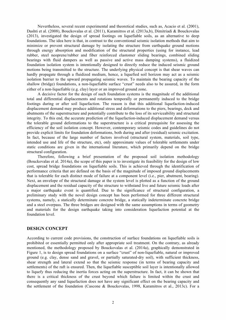
According to current code provisions, the construction of surface foundations on liquefiable soils is prohibited or essentially permitted only after appropriate soil treatment. On the contrary, as already mentioned, the methodology proposed by Bouckovalas et al. (2014a), graphically demonstrated in Figure 1, is to design spread foundations on a surface “crust” of non-liquefiable, natural or improved ground (e.g. clay, dense sand and gravel, or partially saturated-dry soil), with sufficient thickness, shear strength and lateral extend so that the seismic response (in terms of bearing capacity and settlements) of the raft is ensured. Then, the liquefiable susceptible soil layer is intentionally allowed to liquefy thus reducing the inertia forces acting on the superstructure. In fact, it can be shown that there is a critical thickness of the crust beyond which failure is limited within the crust and consequently any sand liquefaction does not have any significant effect on the bearing capacity and the settlement of the foundation (Cascone & Bouckovalas, 1998, Karamitros et al., 2013c). For a

A.Sextos, N.Psilla, I.Psycharis, A.Kappos, O.Taskari, I.Vassilopoulou, E.Mylona, C.Gantes and G.Bouckovalas 3
thinner crust, the dimensions of the shallow foundations are determined through an iterative procedure, considering the tolerance of the superstructure to the significant shear strength degradation of the underlying (liquefiable) layer at the end of shaking and the accumulated settlements during seismic shaking.
Figure 1. Schematic representation of the design concept (Bouckovalas et al., 2014a).
PROOF OF CONCEPT
Given the particular characteristics of the proposed methodology, it is evident that the current seismic code framework is not adequate for designing bridges with shallow foundations on liquefaction susceptible soils. Along these lines, the design process needs to be tailored to the salient features of the novel soil isolation concept, while at the same time complying with the legislative requirements of seismic code provisions. Along these lines, a two stage procedure is prescribed herein, involving (a) initial design of the foundation and the superstructure according to modern seismic codes (the Eurocodes for the present study) after appropriate adaptations to account for the effect of liquefaction on the design inertial loads and displacements, and (b) verification of the bridge capacity to safely accommodate liquefaction-induced transient and permanent displacements in case that the latter exceed the tolerance of the structure for the design earthquake. To further assess the feasibility of the above methodology, performance criteria are also proposed based on the residual capacity of the bridge to bear the traffic and future design earthquake loads as a function of the magnitude of the imposed post-earthquake ground displacement. BRIDGE DESIGN Thickness of the liquefiable soil.
An important first step in designing shallow bridge foundations on liquefiable soils is to ensure that the thickness of the potentially liquefiable soil layer is adequate to act as a source of seismic isolation. As no such quantitative limit is prescribed in contemporary seismic codes and also due to the complexity of the liquefaction phenomenon itself, which is inevitably a multi-parametric and case-dependent phenomenon, the particular isolation ability has to be justified by a site specific seismic response analysis of the liquefiable soil profile (e.g. Bouckovalas et al., 2014b). In the absence of such specialized analyses, Bouckovalas et al. (2013) recommend that the minimum required thickness of the liquefiable layer below the non-liquefiable crust may be approximately taken as (1/5÷1/15)λ, where λ=Vs,oTexc corresponds to the predominant wave length of the seismic waves propagating through the liquefiable soil layer and Vs,o is the initial (prior to liquefaction) average shear wave velocity (Bouckovalas et al. 2013). Note, however, that the relevant research is still in progress and consequently the above recommendation should be used with caution. Seismic scenario and shallow foundation design
Next, the shallow foundation has to be designed at every pier based on the support-dependent soil properties and the design parameters involved. The latter are related (Bouckovalas et al., 2014a) to the soil properties (density of the natural soil Dr, excess pore pressure ratio in the improved zone, ru,design, Buoyant unit weight, γ'), soil geometry of the liquefiable and the improved zone, earthquake ground motion properties in terms of maximum acceleration, predominant period and number of

4
cycles, footing geometry as well as the maximum tolerable displacements and rotations. Given that the latter are not yet known at this stage, it is necessary to decide the recurrence period of the earthquake for which the above deformations shall not be exceeded thus ensuring the Immediate Use performance level. Apparently, for stronger ground motions (i.e., longer periods of earthquake recurrence) deformations will be larger and the bridge may experience a level of (repairable) damage. Limited downtime, however, is deemed acceptable as it complies with the concept of “Life Prevention” or else, the “Limit State of Significant Damage” according to the Eurocode. Seismic ground motion
It is widely accepted that, during liquefaction, excess porewater pressures increase and soil stiffness decreases, leading to the elongation of the characteristic (fundamental) site period, that in turn reduces the tendency of the soil to amplify high frequencies of the upward propagating ground motion. This results in an overall decrease in peak ground acceleration (PGA), with little effect or even amplification of the Peak Ground Velocity and Displacement (PGV and PGD). Along these lines, it is necessary to define and appropriately adapt the design seismic motion at the ground surface, in terms of peak seismic motion parameters and design spectra, before using it as base excitation of the bridge. This alteration is made taking into account the intensely nonlinear, hysteretic response of the liquefied layers in the subsoil. A design spectrum specifically developed for liquefiable soils is also required and has to be generated for the site of interest.
There is a fairly limited number of empirical methodologies to achieve this, although with a widely varying level of approximation (e.g. Bouckovalas et al., 2014b). Alternatively, a suite of input motions recorded on outcrop conditions has to be carefully selected based on the seismic hazard at the site, the seismotectonic characteristics of the area and the different return periods identified by the designer depending on the importance of the structure. In that case, the suite motions have to be duly scaled, so that their average response spectrum is in good agreement with the design spectrum of Eurocode 8 (or other code applicable) for soil type A that approximately resemles the bedrock and for the desired peak ground acceleration (PGA) level (Fig. 2). In the sequel, one-dimensional, nonlinear site response and liquefaction analyses needs to be performed to derive the peak intensity measures (particularly, acceleration and velocity) and the mean 5% damped elastic spectra at the free ground surface. Typical results from such analyses are given in Figure 2, for the site of interest of this study and strong seismic excitations with 1000 years recurrence period (Bouckovalas et al., 2014b).
Figure 2. Outcrop seismic excitation response spectra vs. the EC8 design spectrum for soil type A and PGA=0.32g (left), and corresponding elastic response spectra at the liquefied ground surface (right). Numerical modeling
Having defined the seismic scenario and the resulting design forces, a refined finite element model of the soil-bridge system shall be developed considering the specific features of the problem under study, as conventional soil-foundation-structure interaction modeling techniques are not adequate to capture the dynamic response of the bridge pier on liquefiable soil profiles. Along these lines, analytical relationships (e.g., Mylonakis et al., 2014) may be used for soil springs and dashpot properties which account for the strong mismatch (impedance contrast) in wave propagation velocities between the liquefied soil layers and the upper, non-liquefiable, “crust’’ as well as the highly non-linear hysteretic response of the liquefied soil layers. Another important decision, particularly for short bridges, is related to the extent of soil liquefaction and the possibility to affect the bridge abutments as well. In such a case, due consideration shall be given to the additional alteration of ground motion at
A.Sextos, N.Psilla, I.Psycharis, A.Kappos, O.Taskari, I.Vassilopoulou, E.Mylona, C.Gantes and G.Bouckovalas 5
the lateral supports of the bridge along with the evident modification of the abutment-embankment dynamic impedance. In the common case where liquefaction is only associated with the recent soil formations of the piers at the central part of the bridge, the nonlinear abutment-embankment interaction at the deck ends may be considered based on the large-scale abutment testing results (Lemnitzer et al., 2009; Maroney, 1995) and the subsequent Caltrans Seismic Design Criteria (Caltrans, 2013). Alternatively, more refined procedures may also be adopted for the abutment-embankment stiffness based on other studies (i.e., Zhiang and Makris, 2002, Taskari and Sextos, 2012 among others). In case of seat-type abutments, expansion joints at the deck ends can be modeled through appropriate gap elements, connected in parallel with the pot bearings and in series with the abutment-embankment systems. Analysis for static and seismic loads
First, the structure shall be designed according to the provisions of the conventional code-based procedures, by linear elastic analysis for the static loads acting on the bridge (i.e., gravity and traffic loads). Next, a response spectrum analysis and the subsequent design to the seismic load combination have to be performed. Due to the high level of uncertainty associated with liquefaction phenomenon, two different finite element analysis cases shall be examined corresponding to the case of liquefaction and non-liquefaction, respectively. Distinct finite element models, design spectra and dynamic impedance at the pier footing-soil interface shall be used accordingly.
Imposed displacement demand
Having designed the bridge for the appropriate, liquefaction-dependent, inertial loads, the superstructure shall be able to accommodate the liquefaction-induced ground displacements. It is noted that, the latter are deemd post-earthquake based on the assumption that they are typically maximized asynchronously with the inertial forces primarily due to the relative movement of the (non-liquefiable) abutment soils and the liquefiable pier support soil formations. To this end, the expected level and profile of the imposed displacements and rotations due to liquefaction {δdesign} shall be defined as a separate loading case (imposed displacements/rotations at the footings) according to the expected maximum differential motion between liquefied and non-liquefied soil at the site of interest.
Structural response under the liquefaction-induced imposed displacements and rotations
The previously extracted displacements and rotations due to liquefaction may be then considered according to the combination rule:
δx “+” φy “+” δz “+” 0.30 (δy “+” φx) (1) 0.30 (δx “+” φy) “+” δz “+”δy “+” φx (2)
where δx, δy, δz are the displacements along the longitudinal, transversal and vertical bridge axis, while φx, φy are the corresponding rotations around the longitudinal and the transversal axis. The notation “+” denotes superposition with combination factors that need to defined for the site of interest. These displacements and rotations can be then further combined with the gravity (G) and live (Q) loads using the partial factors for actions according to the applied code (e.g. Eurocode 0). BACK-VERIFICATION OF THE BRIDGE DESIGN FOR THE DESIGN EARTHQUAKE
Due to the high uncertainty level characterizing the liquefaction phenomenon and also the fact that the design is inevitably based on elastic analysis, it is deemed necessary to verify that the bridge designed to the aforementioned methodology, can indeed accommodate the liquefaction-induced displacements and rotations with no damage for the design earthquake. For this purpose, nonlinear static pushover analysis is also envisaged through a procedure that is described in the following. Bridge components, Damage Modes and Engineering Demand Parameters
The critical components for the seismic performance of the bridge (e.g. piers, bearings, foundations, abutments) shall be identified along with their critical damage modes (e.g. bending failure at the piers, shear strain at the bearings, gap closure) the corresponding engineering demand parameters (e.g. bending moment, bearing shear strain) and the associated limit states.
6
Numerical modeling & Nonlinear static pushover analysis
The finite lement model developed for design purposes can be also used for nonlinear static (pushover) analysis after due consideration of the section plasticity (i.e., lumped plasticity or fiber modeling) and specification of the nonlinear analysis parameters. Next, nonlinear static pushover analysis can be performed. At first, gravity loads consisting of dead loads and 20% of live loads (G+0.20Q) need to be considered in the pushover analysis. Notably, pushover analysis due to earthquake loads is not necessary since, according to the assumption already made, no damage in the bridge structural components is expected for the design earthquake and the imposed displacements/rotations are applied at the tail of the ground motion when, the inertia forces are almost zero. The combined displacements and rotations due to potential liquefaction shall be then incrementally applied at the base of the piers up to the level of the target displacements and rotations {δmax}>{δdesign}, which shall be determined by the geotechnical study as the maximum deformation profile that can be probabilistically anticipated for the design earthquake with a more strict confidence level. The geotechnical study shall also define the respective correlation of the ground deformations (displacements, settlements and rotations). Overall, it is expected to verify that no damage shall take place at the superstructure due to most critical assumption for the design earthquake and the corresponding liquefaction-induced displacement combination {δmax}.
RESIDUAL CAPACITY OF THE BRIDGE AS A FUNCTION OF SEISMIC DEMAND
Further to the above verification, it is necessary to ensure that the bridge shall be able to tolerate higher levels of earthquake ground motion intensity with acceptable loss of capacity in bearing traffic (live load) or future design seismic forces. Along these lines, the residual carrying capacity of the bridge structure needs to be defined as a function of the liquefaction-induced permanent displacements. It is noted herein that the latter displacements and rotations may exceed their design values. The same relationship, however, between residual capacity and liquefaction-induced displacement demand may be also used for defining in advance the bridge-specific performance criteria and essentially deciding the applicability of the novel design method based on the target, maximum tolerable, capacity reduction. The procedure to develop the above assessment curve is described in the following. Numerical modeling & Nonlinear static pushover analysis
The finite element model generated for design can be also used at this stage. The assumption can be made that due to strength recovery of the liquefied soil layers after the earthquake, the initial (non-liquefied) soil properties can be used in defining the dynamic impedance at the pier footing-soil interface. Nonlinear static pushover analysis can then be performed first considering dead and live loads (G+Q). Live loads are assumed to be computed with a unity partial loading factor given that after the design earthquake, the traffic is considered to be fully recovered due to the lack of structural damage. Pushover analysis due to earthquake loads is also not performed for the same reason. The combined residual displacements and rotations due to liquefaction are then incrementally applied at the base of the piers up to their maximum target values {δmax}. Next, the demand over capacity ratio (DCR) is computed separately for every bridge component (pier, abutment, prestressed deck slab, bearing, abutment etc.) and individual damage mode as well as level of imposed displacements and rotations {δ}. The corresponding q/q0 ratio may then be derived for every bridge component and damage mode of interest, where q0 is the traffic (live) load that the bridge was initially designed to withstand and q is the residual traffic load that the bridge can still bear without exceeding the capacity in any of the structural members examined. Apparently, if the demand/capacity ratio of a given member is less than one, that is, the capacity of the member is not exceeded, then the q/q0 ratio is set equal to 1.0. On the other hand, if the demand over capacity ratio of the examined member under a deformation level {δ} is greater than unity, the traffic load q is gradually reduced until there member capacity matches the design seismic demand. The procedure is repeated for the member under study until the maximum combined displacements and rotations {δmax} are reached. The series of (δ, q/q0) pairs dictates the variation of residual capacity with the imposed liquefaction-induced deformation for the particular member and failure mode.

A.Sextos, N.Psilla, I.Psycharis, A.Kappos, O.Taskari, I.Vassilopoulou, E.Mylona, C.Gantes and G.Bouckovalas 7
Figure 3. Indicative plot of the ratio q/q0 as a function of the combined displacements and rotations induced {δ}
Figure 4. Envelope of the q/q0 ratio as a function of the induced combined displacements and rotations {δ}
Α schemantic q/q0 versus {δ} curve is presented in Figure 3 for illustration purposes. The q/q0
versus {δ} curves are derived for every examined bridge component and damage mode and the lower envelope of minimum residual capacity is plotted for each deformation level (Fig. 4). Similarly, the ag/ag0 ratio can be plotted with the imposed displacement, where ag0 is the value of the ground acceleration used in the design of the bridge, and ag is the ground acceleration that the bridge can still bear without exceeding the capacity in any of the structural members examined. The ag/ag0 ratio essentially expressing the residual capacity of the bridge to resist a future (design) earthquake after experiencing soil liquefaction.
CASE STUDIES
To demonstrate the applicability of the procedure presented above and prove the feasibility of the novel soil isolation concept, three different bridge configurations are examined. Common assumptions were made wherein possible for compatibility purposes. The site-specific spectrum of Figure 2, is adopted for design appropriately modulated to resemble the Eurocode 8 design spectrum for a recurrence period of T=1000 years. For this purpose, the spectrum parameters are set equal ΤC΄=1,25TC, S = 0.80 and PGA = 0.32g. All bridges were deliberately selected with approximately equal overall and span length, while the normalized vertical load at the piers were also kept of the same level. Abutments were assumed identical with a backwall height of 2.0m and supported on firm (non-liquefiable) soil formations.
q/q0
1.0
Combined displacement {δ}
{δ}
q/q0 ({δ})
q/q0
Combined displacement {δ}
1.0
0.0 {δdes.} {δmax}
Component 1
Component 2
Component 3
Envelope

8
Figure 5. Longitudinal section of the statically determinate concrete bridge
Figure 6. Cross section of the bridge deck
STATICALLY DETERMINATE CONCRETE BRIDGE
The first structural system considered is a statically determinate, two-span (2×42.00 m) concrete bridge crossing a river (Fig. 5). The deck is 11.25m wide, plus 1.25 m wide pavements at each side. The deck cross section is illustrated in Figure 6. The deck is composed of 2×7 precast, prestressed concrete beams of length 40.50m, which are resting upon the abutments and the mid-pier via elastomeric bearings. The pier is a wall-type column, 1.50 m thick and 9.85 m wide, founded on a soil prone to liquefaction under seismic action. The conventional design of the deep foundation on liquefiable soil involved 3×4 ∅120 concrete piles of 25.00m length, combined with improvement of the liquefiable soil layers. The bridge was redesigned for static and seismic load combinations, taking into account the above design spectrum. The pier column was reinforced with 260 rebars of 20mm diameter, while 4 tendons 12T15 of yielding stress 1600 MPa were used for the prestress of each deck beam. The sensitivity of the bridge’s structural components to the imposed foundation displacements, at the footing of the mid-pier, caused by the different ground motion of the pier, compared with the motion of the abutments, due to subsoil liquefaction, was then investigated according to the procedure described above. More precisely, the deformation profile was imposed at the base of the pier, along with the permanent gravity loads and 20% of the traffic loads, assuming that such residual displacements are produced at the foundation level close to the end of shaking. The analysis showed that the maximum horizontal displacement that can occur at the foundation level without exceeding the design resistance of any member is 0.30m in the longitudinal direction of the bridge and much larger in the transverse direction. As already explained, any residual displacement at the pier foundation level reduces the capacity of the bridge to survive future earthquakes. An investigation of the “residual” capacity of the bridge to resist earthquake loads was performed as a function of the ground acceleration, ag. The corresponding ag/ag0 ratio was computed for all critical structural members (superstructure, pier, bearings) through a procedure of gradually increased horizontal displacement at the base of the pier until each member reached its design limits. It is observed that the most critical structural member is the pier, which essentially dictates the tolerance of the entire system to liquefaction-induced deformations.

A.Sextos, N.Psilla, I.Psycharis, A.Kappos, O.Taskari, I.Vassilopoulou, E.Mylona, C.Gantes and G.Bouckovalas 9
Figure 7. Residual seismic capacity against future earthquakes at the component and system level versus the
imposed horizontal displacement at the base the pier.
Another observation is that the magnitude of tolerable horizontal ground displacement is not small, as the bridge can sustain up to 0.20m without reduction in the capacity of any structural member to resist the design earthquake. This may be attributed to the overstrength provided to the structural components that ultimately increases the actual capacity of the bridge.
It should be noted that the sensitivity analysis shown in Figure 7 serves only as an example of the proposed procedure, since it refers solely to the permanent horizontal ground displacement at the foundation level of the pier. Other types of displacements and rotations should also be considered and combined according to Eqs. (1) and (2) and Figure 7 should be plotted for the combined imposed displacement (see Fig. 4). Of course, some displacements/rotations are not critical for the considered type of bridge which is statically determinate. For example, this bridge can sustain large vertical displacements without loss in static and seismic load bearing capacity. Vertical settlements are the main permanent displacements induced to the ground due to liquefaction while residual horizontal displacements caused by the nonlinear response of the soil are expected to be small. However, vertical displacements are expected to trigger other types of displacements/rotations as well. For example, it is widely known that vertical foundation settlement, ρ, is statistically related with tilting, φ of the foundation according to the following empirical relationship between liquefaction-induced permanent tilting (in degrees), and settlement (in cm) of surface foundations (Yasuda et al., 2001, Yasuda 2014):
φ = 0.05⋅ρ (3)
STATICALLY INDETERMINATE REINFORCED CONCRETE BRIDGE The second bridge studied is a statically indeterminate three-span concrete overpass with a
length of 99m. This bridge is part of the 680km long Egnatia Highway that has been recently constructed in northern Greece. The two outer spans have a length of 27.0m each, while the middle span is 45.0m long. The slope of the structure along the bridge axis is equal to 7%. The deck consists of a 10m wide, prestressed concrete box girder section and the two piers are designed with a solid circular RC section of diameter equal to 2.0m. Both piers are monolithically connected to the deck. The heights of the left and the right pier are 7.95m and 9.35m, respectively, reinforced with two series of 48 longitudinal bars of 25mm diameter, spaced equally around the section perimeter. The transverse reinforcement consists of an outer spiral of 14mm diameter, spaced at 75mm and an inner 16mm spiral, also equally spaced. The deck is supported on seat-type abutments, through two pot bearings with dimensions 350×450×136mm that permit sliding along the two principal bridge axes. Sliding joints of 10cm and 15cm separate the deck from the abutment along the longitudinal and the transverse direction, respectively. The pier footings are 9.0m long by 8.0m wide and 2.0m thick, while the footings supporting the abutments are 12.0×4.5×1.5m. The bridge is designed to the aforementioned common design spectrum. An overview of the bridge configuration is illustrated in Figure 8. As previously, the ag/ag0 ratio was derived for all the critical bridge components (piers, bearings,

10
abutments). Figure 9 illustrates indicative results of the ag/ag0 ratio as a function of the imposed horizontal displacement at the pier footings. It is observed that up to 0.20m, the bearings at the deck ends are the dominant components, while for higher level of horizontal ground displacements, the abutments become the most critical structural members. Overall, the bridge was able to tolerate a horizontal displacement of 0.08m without reduction in the capacity of any structural member.
Figure 8. Bridge configuration
Figure 9. Residual seismic capacity against future earthquakes at the component and system level versus the
imposed horizontal displacement at the base the pier.
STEEL ARCH OVERPASS
The third bridge is a steel arch road bridge with two simply supported spans of total length
87.60m. The total width of the deck is equal to 15.00m, while at the supports it becomes 15.55m. The steel members of each span include two main beams with HEB900 section, 17 HEB900 transverse beams, two CHS750/20 arches, connected with a bracing system consisting of CHS244.5/8 transverse members and CHS139.7/8 diagonal members. Each main beam is suspended from the corresponding arch with seven struts with cross section CHS168.3/6.3. The distance between adjacent transverse steel beams is 2.625m. A 35cm thick composite deck is formed using trapezoidal profiles of type SYMDECK 150 and a concrete slab, connected with the transverse and main beams through steel shear connectors. The pier consists of three circular reinforced concrete columns, 8.00m tall, having a circular cross section of 1.70m diameter. The distance between the three columns is equal to 7.35m. They are connected at the top with a 17.00m long concrete beam. The footing’s dimensions are 14.00m x 15.00m and its thickness is 2.00m. The deck is supported by the pier and the abutments via anchored elastomeric bearings of type NB4 800x800x305 (180). Εxpansion joints of type Algaflex TM 640 are used at the abutments due to the required gap. The model of the bridge is illustrated in Figure 10. The analysis of the bridge under seismic load combinations, taking into account the aforementioned design spectrum with ground acceleration ag0, resulted in a reinforcement of the piers

A.Sextos, N.Psilla, I.Psycharis, A.Kappos, O.Taskari, I.Vassilopoulou, E.Mylona, C.Gantes and G.Bouckovalas 11
of 46Φ28 and a required gap at the abutments of 350mm. The sensitivity of the bridge to imposed foundation settlements due to potential liquefaction of the soil was then investigated. Without exceeding the capacity of the pier defined by its reinforcement, the maximum permissible horizontal displacements at the footing were estimated, was found 0.64m in the longitudinal x-direction and 1.07m in the transverse y-direction. For that purpose, the imposed displacements were combined with the permanent loads only, increased by the partial factor of 1.35, when acting unfavorably. Then, an appropriate percentage of these displacements was included in the seismic loading combinations, in order to evaluate the bridge’s capacity to sustain a future earthquake when foundation displacements have previously taken place. Increasing the displacements from zero up to their computed value in the previous step, the future earthquake, with ground acceleration ag, was estimated.
Figure 10. Finite element model of the arched steel bridge
Figure 11. Residual seismic capacity for the future design earthquake at the component and system level versus
the imposed horizontal displacement at the base the pier.
As previously, this essentially dictated the level of seismic acceleration that the bridge could sustain with the given geometry, cross-sections and reinforcement. As shown in Fig. 11, three structural components were monitored, namely, the bearing capacity of the piers, the maximum displacement of the bearings, and the closing of the gap at the expansion joints. It is observed that in the longitudinal direction, the most critical is the pier, while in the transverse direction, the closing of the gap and the bearings dictate the tolerable displacements at the system level.
CONCLUSIONS
The feasibility of designing bridges with shallow foundations over potentially liquefiable soil profiles is presented in this paper. The concept of natural soil isolation is briefly discussed and proof of concept is provided based on deformation-based performance criteria, the distinct modes of failure of the critical superstructure components and the residual capacity of the structure to withstand traffic and future seismic loads after the subsoil has liquefied during a major earthquake event. Calculations are further back-verified for the case that the ground deformations exceed the design ones. Comparative application of the proposed design and verification procedure indicates that, depending on the structural system and the direction of excitation examined, different bridges may tolerate a different level of transient and permanent foundation displacements without any significant structural
0
0.2
0.4
0.6
0.8
1
1.2
0 0.2 0.4 0.6 0.8
FOUNDATION DISPLACEMENT +X (m)
ag/a
g0
PIER BEARINGS GAP
0
0.2
0.4
0.6
0.8
1
1.2
0 0.2 0.4 0.6 0.8 1 1.2
FOUNDATION DISPLACEMENT +Y (m)
ag/a
g0
PIER BEARINGS GAP

12
damage and without any noticeable decrease of their serviceability. The applicability of the novel foundation design methodology is also demonstrated. Further research is currently under way to reliably define the range of application of the proposed design method.
ACKNOWLEDGMENTS
This research has been co-financed by the European Union (European Social Fund – ESF) and Greek national funds through the Operational Program “Education and Lifelong Learning” of the National Strategic Reference Framework (NSRF) – Research Funding Program: THALES: Reinforcement of the interdisciplinary and/or inter-institutional research and innovation.
REFERENCES
Acacio AA, Kobayashi Y, Towhata I, Bautista RT, Ishihara K (2001) “Subsidence of building foundations resting upon liquefied subsoil: Case studies and assessment”, Soil and Foundations, 41(6): 111-128.
Bouckovalas G., Theocharis A., Tsiapas Y., Chaloulos Y., (2013) “Numerical Analysis of Liquefied Ground Response”, International Conference on Earthquake Geotechnical Engineering: from Case History to Practice, Istanbul, Turkey, June 17 – 19.
Bouckovalas GD, Karamitros D, Chaloulos Y, Vavourakis V and Chatziharalambous E (2014a) “Analytical methodology for the design of shallow foundations on liquefiable soil”, Research Report D3, Foundation Engineering Laboratory (NTUA).
Bouckovalas GD, Loukidis D, Chaloulos Y, Tsiapas D and Chatziharalambous E (2014b) “Design spectra for liquefiable ground”, Research Report D4, Foundation Engineering Laboratory (NTUA).
Bouckovalas GD, Madabhushi S (2011) “Experimental Verification of Shallow Foundation Performance under Earthquake-induced Liquefaction”, Research Report, Foundation Engineering Laboratory (NTUA) in cooperation with The Schofield Center of Cambridge University.
Dimitriadi V, Bouckovalas G, (2013) “Numerical Simulation of Seismically Induced Settlements of Shallow Foundations on Remediated Ground against Liquefaction”, International Conference on Earthquake Geotechnical Engineering: from Case History to Practice, Istanbul, Turkey, June 17 - 19.
Caltrans (2013) Seismic Design Criteria Version 1.7. California Dept of Transportation: Sacramento, CA, U.S. Cascone E., Bouckovalas G. (1998) “Seismic bearing capacity of footings on saturated sand with clay cap”,
Proceedings 11th European Conference on Earthquake Engineering, Paris, September (in CD-ROM). Dashti S, Bray J, Riemer M, Wilson D (2008) “Centrifuge experimentation of building performance on liquefied
ground”, Geotechnical Special Publication, (181). FHWA (1987) Spread Footings for Highway Bridge, Report No. FHWA RD-86-185, Authors: Gifford DG,
Kraemer SR, Wheeler JR and McKown AF, Federal Highway Administr., U.S. Dept of Transportation. FHWA (1982) Performance of Highway Bridge Abutments on Spread Footings on Compacted Fill, Report No.
FHWA RD-81-184, DiMillio AF, Federal Highway Administration, U.S. Department of Transportation. Karamitros D, Bouckovalas G, Chaloulos Y (2013a) “Insight to the Seismic Liquefaction Performance of
Shallow Foundations”, Journal of Geotechnical and Geoenvironmental Engineering, ASCE, Vol. 139 (4) Karamitros D, Bouckovalas G, Chaloulos Y (2013b) “Seismic settlements of shallow foundations on liquefied
soil with a clay crust”, Soil Dynamics and Earthquake Engineering, 46: 61-76. Karamitros D, Bouckovalas G, Chaloulos Y, Andrianopoulos K (2013c): “Numerical analysis of liquefaction-
induced bearing capacity degradation of shallow foundations on a two-layered soil profile”, Soil Dynamics and Earthquake Engineering, 44: 99-101
Lemnitzer A, Ahlberg E, Nigbor R, Shamsabadi A, Wallace J and Stewart J (2009) “Lateral Performance of Full-Scale Bridge Abutment Wall with Granular Backfill”,. Journal of Geotechnical and Geoenvironmental Engineering, 135(4): 506–514
Maroney B (1995) Large scale bridge abutment tests to determine stiffness and ultimate strength under seismic loading, PhD Thesis, Dept. of Civil Engineering, University of California Davis, CA.
Mylonakis G, Bouckovalas G, Karatzia X, Tsiapas Y and Chatziharalambous E (2014) Soil springs and dashpots for footings on liquefiable soil, Research Report D5, University of Patras
Sargand SM and Masada T (2006) Further Use of Spread Footing Foundations for Highway Bridges, State Job Number 14747(0) Final Report FHWA-OH-2006/8, Final Report to Ohio Dept. of Transportation
Taskari O and Sextos A (2012) “Stiffness and Ultimate Capacity of Typical Abutment- Embankment Systems”, Proceedings of the 15th World Conference on Earthquake Engineering, Lisbon, Portugal.
Zhang J and Makris N (2002) “Kinematic response functions and dynamic stiffnesses of bridge embankments”, Earthquake Engineering and Structural Dynamics, 31: 1933–1966.