performance enhancement of bridge bracing under service ... · portland state university pdxscholar...
TRANSCRIPT

Portland State UniversityPDXScholar
TREC Final Reports Transportation Research and Education Center(TREC)
12-2010
Performance Enhancement of Bridge Bracing Under Service andExtreme LoadsPeter DusickaPortland State University
Max Taylor StephensPortland State University
Kate Fox-LentPortland State University
Let us know how access to this document benefits you.Follow this and additional works at: http://pdxscholar.library.pdx.edu/trec_reports
Part of the Transportation Commons, Urban Studies Commons, and the Urban Studies andPlanning Commons
This Report is brought to you for free and open access. It has been accepted for inclusion in TREC Final Reports by an authorized administrator ofPDXScholar. For more information, please contact [email protected].
Recommended CitationChristopher Monsere, Lisa Diercksen, Karen Dixon and Michael Liebler. Evaluating the Effectiveness of the Safety InvestmentProgram (SIP) Policies for Oregon. OTREC-RR-10-11. Portland, OR: Transportation Research and Education Center (TREC),2009. https://dx.doi.org/10.15760/trec.71

A National University Transportation Center sponsored by the U.S. Department of Transportation’s Research and Innovative Technology Administration
OREGON TRANSPORTATION RESEARCH AND EDUCATION CONSORTIUM OTREC
FINAL REPORT
Performance Enhancement
of Bridge Bracing Under Service and Extreme Loads
OTREC-RR-10-17 December 2010


PERFORMANCE ENHANCEMENT OF BRIDGE BRACING UNDER SERVICE AND EXTREME LOADS
OTREC-RR-10-17
by
Peter Dusicka, PhD, PE
Assistant Professor
email: [email protected]
phone: (503) 725-9558
Portland State University
Max Stephens, Research Assistant
and
Kate Fox-Lent, Research Assistant
for
Oregon Transportation Research
and Education Consortium (OTREC)
P.O. Box 751
Portland, OR 97207
December 2010


i
Technical Report Documentation Page 1. Report No.
OTREC-RR-10-17
2. Government Accession No.
3. Recipient’s Catalog No.
4. Title and Subtitle
Performance Enhancement of Bridge Bracing Under Service and Extreme Loads
5. Report Date
December 2010
6. Performing Organization Code
7. Author(s)
Peter Dusicka, Assistant Professor
Max Stephens, Research Assistant
Kate Lent-Fox, Research Assistant
8. Performing Organization Report No.
9. Performing Organization Name and Address
Portland State University
Department of Civil and Environmental Engineering
PO Box 751
Portland, OR 97207
10. Work Unit No. (TRAIS)
11. Contract or Grant No.
12. Sponsoring Agency Name and Address
Oregon Transportation Research
and Education Consortium (OTREC)
P.O. Box 751
Portland, Oregon 97207
13. Type of Report and Period Covered
14. Sponsoring Agency Code
15. Supplementary Notes
16. Abstract
The purpose of this study was to develop and demonstrate the concept of retrofitting bridge brace elements with fiber reinforced composites in
order to provide restraint against buckling. The advanced materials consisted of a combination of fiber reinforced polymer (FRP) composite
pultruded sections and wet lay-up wraps, intended to be applied in the field. A selected number of prototype retrofit bracing specimens were
constructed and tested using reverse cyclic loading, and the performance of these specimens was characterized by their compressive strength
and their overall hysteretic behavior.
The results of this exploratory study have shown that slender bracing members retrofitted with FRP sections show an improved level of
performance. All retrofitted specimens showed an improved compressive strength in the linear elastic and plastic deformation range of the
slender bracing member. The cyclic behavior exhibited only a marginal improvement, however, due to failure modes at the bolted connections
of the brace. Further modification of the brace had marginally improved the cyclic performance. Despite the challenges associated with the
connection failures of the retrofitted members, the demonstration has shown that the developed concept of applying fiber reinforced composites
has a potential to effectively restrain slender bracing members from buckling and improve the compressive resistance. Further testing needs to
be conducted to evaluate a more optimal implementation for resisting cyclic loads.
17. Key Words
bridge, steel bracing, retrofit, fiber reinforced polymer (FRP)
18. Distribution Statement
No restrictions. Copies available from OTREC:
www.otrec.us
19. Security Classification (of this report)
Unclassified
20. Security Classification (of this page)
Unclassified
21. No. of Pages
28
22. Price

ii

iii
ACKNOWLEDGEMENTS
This project was funded by the Oregon Transportation Research and Education Consortium
(OTREC) and Portland State University. Their support is gratefully acknowledged.
DISCLAIMER
The contents of this report reflect the views of the authors, who are solely responsible for the
facts and the accuracy of the material and information presented herein. This document is
disseminated under the sponsorship of the U.S. Department of Transportation University
Transportation Centers Program in the interest of information exchange. The U.S. Government
assumes no liability for the contents or use thereof. The contents do not necessarily reflect the
official views of the U.S. Government. This report does not constitute a standard, specification,
or regulation.

iv

1
TABLE OF CONTENTS EXECUTIVE SUMMARY ............................................................................................................ 3
1.0 INTRODUCTION .............................................................................................................. 5
1.1 BACKGROUND ................................................................................................................ 5
1.2 LITERATURE REVIEW ................................................................................................... 5
1.3 FIBER REINFORCED POLYMER................................................................................. 6
2.0 TEST SETUP .................................................................................................................... 8
2.1 TEST MATRIX .................................................................................................................. 8
2.2 TEST SPECIMEN ............................................................................................................ 9
2.2.1 Steel Angle Members .............................................................................................. 9
2.2.2 Buckling Restraint FRP Sections ........................................................................... 9
2.2.3 Application of FRP Sections ................................................................................. 10
2.2.4 Modified Specimens ................................................................................................. 11
2.3 TEST APPARATUS ....................................................................................................... 12
2.4 INSTRUMENTATION .................................................................................................... 13
2.5 LOADING PROTOCOL .................................................................................................. 14
3.0 SUMMARY OF RESULTS ........................................................................................... 15
3.1 TEST OBSERVATIONS ................................................................................................ 15
3.2 FAILURE MODES .......................................................................................................... 16
3.3 CYCLIC BEHAVIOR ..................................................................................................... 18
4.0 FUTURE TESTING ........................................................................................................ 25
5.0 SUMMARY AND CONCLUSION ................................................................................ 26
6.0 REFERENCES..................................................................................................................... 27
2
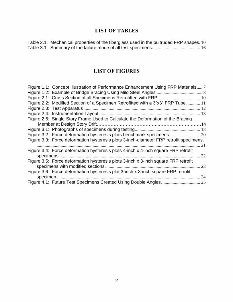
LIST OF TABLES
Table 2.1: Mechanical properties of the fiberglass used in the pultruded FRP shapes. 10
Table 3.1: Summary of the failure mode of all test specimens. ......................................... 16
LIST OF FIGURES
Figure 1.1: Concept Illustration of Performance Enhancement Using FRP Materials ..... 7
Figure 1.2: Example of Bridge Bracing Using Mild Steel Angles ........................................ 8
Figure 2.1: Cross Section of all Specimens Retrofitted with FRP. .................................... 10
Figure 2.2: Modified Section of a Specimen Retrofitted with a 3”x3” FRP Tube. ........... 11
Figure 2.3: Test Apparatus ...................................................................................................... 12
Figure 2.4: Instrumentation Layout. ....................................................................................... 13
Figure 2.5: Single-Story Frame Used to Calculate the Deformation of the Bracing Member at Design Story Drift…………………………………..………………….……14
Figure 3.1: Photographs of specimens during testing. ........................................................ 18
Figure 3.2: Force deformation hysteresis plots benchmark specimens. .......................... 20
Figure 3.3: Force deformation hysteresis plots 3-inch-diameter FRP retrofit specimens................................................................................................................................................ 21
Figure 3.4: Force deformation hysteresis plots 4-inch x 4-inch square FRP retrofit specimens. .......................................................................................................................... 22
Figure 3.5: Force deformation hysteresis plots 3-inch x 3-inch square FRP retrofit specimens with modified sections. .................................................................................. 23
Figure 3.6: Force deformation hysteresis plot 3-inch x 3-inch square FRP retrofit specimen ............................................................................................................................. 24
Figure 4.1: Future Test Specimens Created Using Double Angles. ................................. 25

3
EXECUTIVE SUMMARY
The demand on aging bridges continues to increase under service loads resulting from
progressively larger truck loads, and under extreme loads resulting from engineers’ improved
understanding of the seismic risk. Truss bridges, steel girder diaphragms and braced
substructures are comprised of slender steel structural elements that are crucial in resisting
various loads and are typically designed primarily for tension. Their susceptibility to buckle
under compressive loads results in compressive resistance that is well below the yield strength
capacity, a contribution often discounted in design. Also, buckling induced asymmetric and
pinched hysteretic behavior of these elements typically results in degrading hysteretic energy
dissipation under seismic loading and can lead to premature failure caused by localized plastic
strains. A retrofit measure was experimentally investigated in order to increase load capacity by
enhancing the compressive resistance under monotonic loading and to improve the seismic
response under cyclic loads.
A buckling restrained brace (BRB) was recently developed for buildings as a structural member
that is capable of attaining compression strength governed by material yielding rather than global
buckling. This is achieved by encasing a ductile core in a steel tube filled with mortar. The steel
tube and mortar act to restrain the encased member from buckling, thereby increasing its
compressive strength. Furthermore, BRBs have the advantage of exhibiting ductile behavior in
cyclic tension and compression, making them well suited for resisting earthquake loads. BRBs
have been primarily used for new building construction and are not always suitable for bridge
retrofits due to their heavy weight, specialized connection requirements and the need for
complete member replacement. However, the concept of externally restraining buckling along
the length of the member can have a direct impact as an effective retrofit measure for bridges
with slender steel elements. Accordingly, this report develops and demonstrates the concept of
retrofitting bridge brace elements with fiber reinforced polymer (FRP) materials in order to
provide restraint against buckling. A selected number of prototype retrofit bracing specimens
were constructed and tested using reverse cyclic loading. The performance of these specimens
was characterized by their compressive strength and their overall hysteretic behavior.
The results of this exploratory study have shown that slender bracing members retrofitted with
FRP sections show an improved level of performance. All retrofitted specimens showed an
improved compressive strength in the linear elastic and plastic deformation range of the slender
bracing member. The cyclic behavior exhibited only a marginal improvement, however, due to
failure modes at the bolted connections of the brace. Further modification of the brace
marginally improved the cyclic performance. Despite the challenges associated with the
connection failures of the retrofitted members, the demonstration has shown that the developed
concept of applying fiber reinforced composites has a potential to effectively restrain slender
bracing members from buckling and improve compressive resistance. Further testing needs to be
conducted to evaluate a more optimal implementation for resisting cyclic loads.

4

5
1.0 INTRODUCTION
1.1 BACKGROUND
The demand on aging bridges continues to increase under service loads resulting from
progressively larger truck loads, and under extreme loads such as earthquakes resulting from
engineers’ improved understanding of the risk. Since bridges form an integral part of the
transportation infrastructure, their integrity is crucial to maintaining the proper function and
efficiency of the transportation network. Steel girder bridge diaphragms, truss spans and braced
substructures are often comprised of slender structural elements that are crucial in resisting
various loads and are typically designed primarily for tension. Their susceptibility to buckle
under compressive loads results in compressive resistance that is well below the yield strength
capacity. The compression contribution is often discounted in design, but if utilized to its full
potential can present additional load-carrying capacity for the structure. Under seismic loading,
which is characterized by large reversed deformation cycles, asymmetric and pinched hysteretic
behavior of buckled elements results in degrading hysteretic energy dissipation. More
importantly, localized plastic strain caused by the bending and straightening can lead to failure
under a low number of reversals (Park et al 1996).
Means of retrofitting these types of structural components for earthquakes is limited to primarily
field welding strengthening methods (FHWA 2006). Enhancing the compression capacity by
delaying or minimizing buckling would lead to improved performance under these extreme
loading conditions. With many lift span and truss bridges in the Portland area, the benefit would
be realized regionally. It also would have an impact nationally as steel bridges with bracing
elements were a common means to span longer distances and many are nearing the end of their
design life. A new method is needed that takes advantage of modern materials.
A buckling restrained bracing (BRB) was recently developed for new building construction as a
structural member that is capable of attaining compression strength that is governed by material
yielding rather than global buckling. This is achieved by encasing a ductile core with a steel tube
filled with mortar, which restrains the steel core from buckling (Black et al 2004, Lai & Tsai
2004). Special interface material between the steel core and the mortar allows for plastic strains
in the core without composite action, thereby limiting the strength to a desired and
predetermined value. BRBs have the advantage of exhibiting ductile hysteretic behavior in
tension and compression, making them well suited for resisting cyclic loads. They have been
exclusively applied to new building construction in order to achieve higher-than-standard levels
of seismic performance. The American Institute of Steel Construction recently added design
provisions for BRBs in their seismic specifications for buildings (AISC 2005), and the industry
has started to adopt them in design.
1.2 LITERATURE REVIEW
In the last few decades, buckling-resistant braced frames have become increasingly popular in
Asia and the western United States as many experimental and analytical studies have

6
demonstrated the effectiveness of BRBs in improving the hysteretic behavior of slender bracing
members. Experimental studies conducted by Rezai et al. (2000), Nakamura et al. (2000), Iwata
et al. (2000), Lai and Tsai (2001), Black et al. (2004), and Xie (2004) investigated the overall
cyclic behavior of BRBs and the effects of various bracing properties on this behavior. In
addition to displaying the improved compressive behavior of restrained bracing members, it was
commonly found that bracing properties such as the type of de-bonding material, section shape,
connection type, and the brace restraint type influence the hysteretic behavior of the braces.
Black et al. (2004) and Dicleli and Calik (2008) additionally utilized experimental data to
develop analytical models to simulate the hysteretic behavior of restrained braces under cyclic
loading. Work by Rezai et al. (2000) and Iwata et al. (2000) expanded the experimental scope of
restrained bracing by examining the use of commercially available BRBs as hysteretic fuse
elements in concentrically steel-braced frames. Both experiments demonstrated the potential for
restrained bracing to be used as hysteretic dampers in steel structures, whereby the bracing
generally demonstrated a stable hysteretic response under cyclic loading. Work by Ko and Field
(2003) summarizes the development of the unbounded brace, and works by Ko and Field (2003),
Xie (2004), and Lai and Tsai (2004) discuss the current uses of restrained bracing in new
construction and seismic retrofits.
1.3 FIBER REINFORCED POLYMER
While buckling restrained bracing has demonstrated much experimental success and has been
implemented in primarily new construction of large buildings, utilizing BRBs for the widespread
retrofit of infrastructure such as bridges presents other different challenges. As current BRBs are
commonly fabricated using traditional materials such as steel tubing and mortar, retrofit
applications are restricted by structure redundancy and weight limitations. It is thus not viable to
utilize current BRB technology on such preexisting structures as bridges where it is less feasible
to remove and replace a large number of members, and undesirable to add significant weight,
surface area or significantly alter the load path. As bridges are of immense public importance,
there is an interest in developing a method with which to retrofit existing bracing members with
light-weight buckling restraints. Accordingly, this report presents study results associated with
the use of light-weight fiber reinforced polymer (FRP) sections to restrain single-angle bracing
members from buckling.
FRP composites are starting to become a viable material for use in our infrastructure, primarily
for the purpose of retrofitting concrete bridge components and also as prefabricated bridge decks.
However, research into FRP composites combined with steel has been extremely limited and
even more so in applications of expected plastic behavior. One of the benefits of using FRP for
retrofit of concrete components is the ability to apply the material in the field to any shape
surface using a wet lay-up process. Such methods are often used to provide confinement for
seismic retrofits of columns or as wrap for deteriorated concrete beams. On the other hand, FRP
bridge decks are prefabricated from pultruded sections, typically in the form of tubes that
provide high strength and stiffness. These can be used as deck replacements to reduce dead load
on bridges; such was the case locally on the Broadway Bridge in Portland (Dusicka et al 2004).
The benefits of the in-field application of FRP and the stiffness characteristics of pultruded
sections are combined with in-situ steel elements to provide a retrofit-based buckling restraint as
conceptualized in Figure 1.1a. Such an application would result in minimal added weight for
gravity loads and surface area for wind loads. Since the pultruded section mainly provides
7
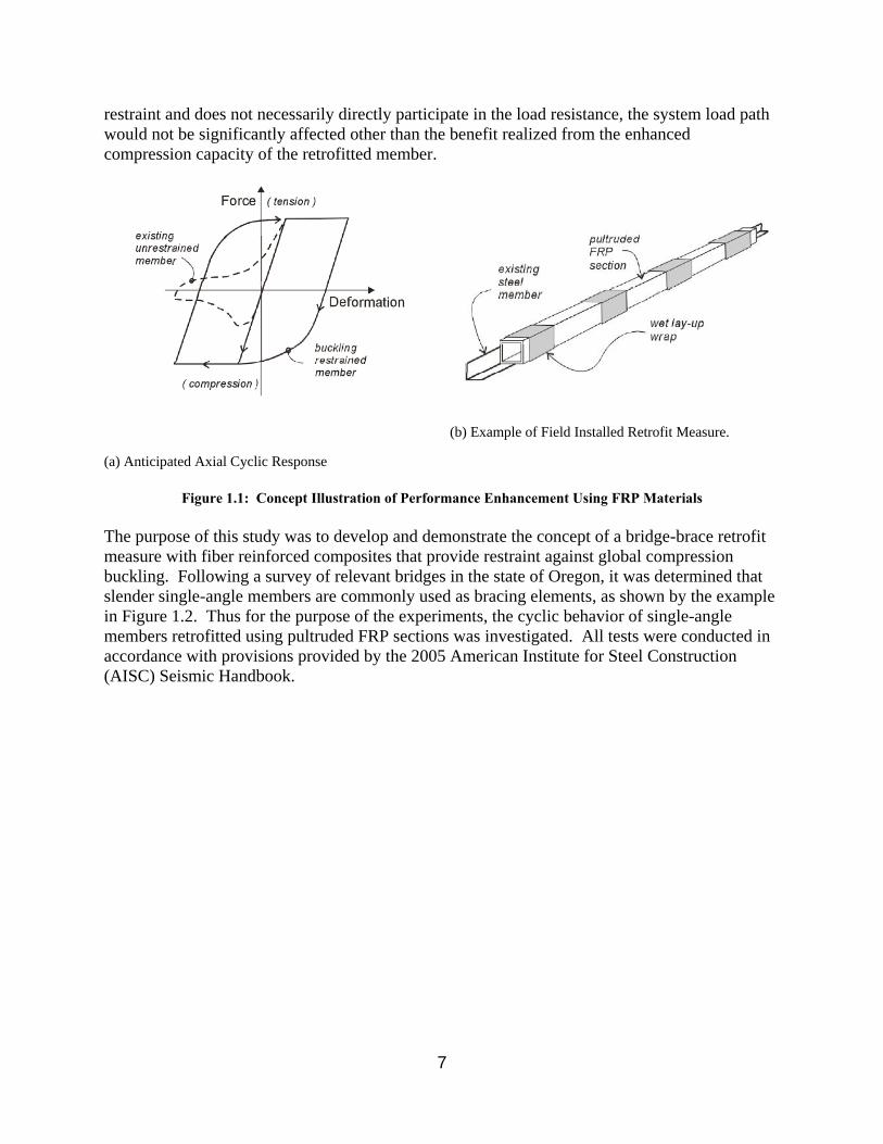
restraint and does not necessarily directly participate in the load resistance, the system load path
would not be significantly affected other than the benefit realized from the enhanced
compression capacity of the retrofitted member.
(a) Anticipated Axial Cyclic Response
(b) Example of Field Installed Retrofit Measure.
Figure 1.1: Concept Illustration of Performance Enhancement Using FRP Materials The purpose of this study was to develop and demonstrate the concept of a bridge-brace retrofit
measure with fiber reinforced composites that provide restraint against global compression
buckling. Following a survey of relevant bridges in the state of Oregon, it was determined that
slender single-angle members are commonly used as bracing elements, as shown by the example
in Figure 1.2. Thus for the purpose of the experiments, the cyclic behavior of single-angle
members retrofitted using pultruded FRP sections was investigated. All tests were conducted in
accordance with provisions provided by the 2005 American Institute for Steel Construction
(AISC) Seismic Handbook.

8
Figure 1.2: Example of Bridge Bracing Using Mild Steel Angles
2.0 TEST SETUP
2.1 TEST MATRIX
Primary testing focused on 2-inch x 2-inch x 1/4-inch angle members retrofitted using pultruded
FRP sections of varying shapes (specimen specifications to be discussed in Section 2.2). Two
tests were conducted on plain angles to obtain benchmark data. At least two specimens were
prepared using each FRP shape, one with a partial fiber wrap and one with a full fiber wrap.
Each member was subjected to a loading program which consisted of increasing displacements
during elastic and post-yield cycles. This protocol follows the loading sequence given in the
AISC Seismic Handbook, and is discussed in Section 2.4.

9
2.2 TEST SPECIMEN
Figure 1.1b depicts the general form of the test specimens used in the study. The specimens
consisted of A36 steel grade 2-inch x 2-inch x 1/4-inchcore angle members and a pultruded FRP
restraining member attached using glass fiber wrap applied around the assembly.
2.2.1 Steel Angle Members
All angle members were from the same mill batch, and had a reported yield strength of 45.9 ksi
and a reported ultimate strength of 70.5 ksi. The 2-inch x 2-inch x1/4-inch angles were chosen
as the core steel sections because they are compact according to AISC table B4.1, which limits
local buckling of the section. These members were cut to a length of 85 inches to accommodate
the dimensions of the test apparatus (specifications to be discussed in Section 3). The critical
buckling load of each specimen was calculated using the equation 2-1 below:
(2-1)
Where Pcr is the critical buckling strength, E is the modulus of elasticity, I is the moment of
inertia of the cross sectional area, k is the effective length factor, and L is the length of the
member. Using the material properties of steel, the geometric properties of the angle sections,
and the constraint properties of the test apparatus, the critical buckling strength was determined
to be 22.3 kips. This value will be compared to the buckling strength of the benchmark
specimens.
In preparing the core angle members for buckling restraint application, the sharp corner of each
member was smoothed using a grinder to effectively increase the outer radius of curvature, and
the mill scale on the legs was left unchanged. Each connection consisted of four staggered
13/16-inch holes for use with A325 ¾-inch bolts, and all connections were reinforced using 1.5-
inch x ¾-inch flat bar to account for the reduced section of the bolted connection. Two 6-inch
lengths of 1.5-inch x ¼-inch flat bar were welded perpendicular to the face of one leg of each
angle, and two 6-inch lengths of ¼-inch threaded rod was welded to the flat bar for use in
instrumentation. Two TML type YFLA-5 post-yield strain gauges were additionally applied to
the outside leg of each core section at approximately Leff/2 and Leff/3. A total of nine members
were prepared in total. Two prepared core members were set aside for use as a control group
while all others were reinforced using restraining members and an epoxy fiber wrap.
2.2.2 Buckling Restraint FRP Sections The pultruded FRP restraining members used in this experiment consisted of series 525
structural shapes manufactured by Strongwell. The shapes used consisted of round tubes with 3-
inch diameters and square-cross-section tubes of 4x4x1/4 inches, 2x2x1/4 inches, and 3x3x1/4
inches. These cross sections are shown in Figure 2.1 and correspond to (a), (b), (c), and (d),
respectively.

10
(a) (b) (c) (d)
Figure 2.1: Cross Section of All Specimens Retrofitted with FRP.
The mechanical properties of the fiberglass used in these pultruded shapes have been provided
by the manufacturer. These values were determined from coupon tests, and are displayed in
Table 2.1. All given values are ultimate properties in the “lengthwise” direction of the structural
shapes. Table 2.1: Mechanical properties of the fiberglass used in the pultruded FRP shapes.
MECANICAL PROPERTY
Tensile Strength LW 30 ksi
Tensile Strength CW 7 ksi
Flexural Strength LW 30 ksi
Flexural Strength CW 10 ksi
Elastic Modulus LW 2500 ksi
Elastic Modulus CW NA
LW = Lengthwise
CW = Crosswise
Two specimens were created using each FRP shape. All restraining sections were cut to lengths
of 60 inches, and were roughened with sand paper in order to promote the bonding of the fiber
wrap. Prior to fixing the prepared restraining sections to the angle members, a de-bonding layer
was placed on the angles in order to reduce friction between the restraining member and the
angle. The de-bonding agent consisted of cellophane wrap.
2.2.3 Application of FRP Sections The final step in preparing the test specimens was to permanently secure the restraining sections
to the angle members. This was accomplished by applying a wet lay-up of epoxy and a fiber
reinforced composite (FRC) to the angle-restraining tube assembly. The lay-up materials
consisted of a 20-foot x 54-inch roll of Tyfo SEH-51 fiber wrap with a strongly unidirectional
weave, and a Tyfo S two part epoxy. To begin the lay-up process the epoxy components were
mixed to the manufacturer’s specification, and were hand worked into precut sections of fiber
weave. The precut sections were measured to provide two uniform layers of fiber wrap to each
specimen. The weave was applied to the angle-restraining tube assembly so that the strong fiber
direction was perpendicular to the length of the angle. As the provided fiber material was not
wide enough to cover the full width of the restraining section, two separate fiber sheets of 54

11
inches and 6 inches were applied to each fully wrapped specimen. Cellophane wrap was used to
tightly secure the wrap to the bracing member. This wrap was kept on each specimen throughout
the curing and testing process. For the purpose of the partially wrapped specimens, fiber wrap
was only applied in 12-inch lengths at the center and each end of the restraining member. All
specimens were given a cure time of at least seven days, and 500-watt lights were used to
expedite the curing process. For separate material property tests, two pieces of 12 inches x 12
inches were also saturated, pressed and layered on top of each other, with the strong-direction
fibers aligned. These were left to cure on a section of polyvinyl sheeting and were later cut to
standard coupon dimensions for tensile testing according to ASTM D 3039. The direction of the
fibers was identified and five strips of fiber wrap, 15 millimeters wide, were cut with their long
dimension parallel to the strong direction of the fibers. The strips were then trimmed to 25
centimeters in length and the ends saved for use as grips during testing. A dozen additional
strips of 2-inch x13-inch fiber wrap were saturated and applied perpendicularly to the outside
face of a section of FRP and on one leg of a piece of angle from the same 2x2x1/4. Two strips
were applied to each section so that each contacted the steel over a 2-inch x 2-inch area, two
strips so that each contacted the steel over a 2-inch x 4-inch area, and two strips so that they
contacted the steel over a 2-inch x 6-inch angle. The same dimensions were used for the fiber
wrap applied to the FRP section. All specimens were saved to test the shear strength of the
surface bond between the fiber wrap and the core angle section.
2.2.4 Modified Specimens In order to alleviate connection failures, modifications to the specimens were made along the
length of three of the specimens. This modification consisted of drilling holes through the cured
fiber wrap and core steel section with the intention of reducing the cross section to weaken the
member. The modified specimens included two of the angle members retrofitted with the 3-inch
x 3-inch FRP tube, and one member retrofitted with the 3-inch-diameter FRP tube. One of the
members retrofitted with the 3-inch x 3-inch square FRP tube was modified by drilling 5/8-inch-
diameter holes at 3 inches center to center, while the other was modified by drilling ¾-inch holes
at 2 inches center to center. The specimen retrofitted with the 3-inch-diameter FRP tube was
modified by drilling ¾-inch holes at 2 inches center to center. Figure 2.2 shows the modified
section of one of the members retrofitted with the 3-inch x 3-inch FRP tube after testing.
Figure 2.2: Modified Section of a Specimen Retrofitted with a 3-inch x 3-inch FRP Tube.

12
2.3 Test Apparatus Figure 2.3 shows the horizontal load frame constructed in order to test the angle specimens. The
beams of the load frame comprised W10x26 with two rows of ¾-inch holes, at a vertical and
horizontal spacing of 4 inches on center, drilled through the web along the entire length. One 19-
foot length was available and one 15-foot length was spliced to a 4-foot length. The two beams
were positioned parallel, 43 ¾ inches apart, and fixed in place by reaction plates bolted between
the beams. The entire assemblage was bolted to pedestals to raise it 12 ¾ inches above the
laboratory floor. A 100 kip hydraulic actuator was secured to one reaction plate such that the
centerline of the actuator aligned with the center of the reaction plate. The load cell for the
horizontal actuator was calibrated using an Omega LC 101 30 kip load cell. The calibration was
determined in terms of voltage output up to 20 kips and was assumed to be linear up to the full
100 kip capacity of the load cell.
Figure 2.3: Test Apparatus

13
2.4 Instrumentation In addition to the two post-yield strain gauges placed on the core steel sections, four strain
gauges were placed on the outside of the fiber wrap. Three gauges, placed 2 inches, 7 inches and
30 inches from the end of the restraining tube, were oriented in order to measure strain along the
strong direction of the wrap. One gauge, placed 30 inches from the end of the wrap, was
oriented in order to measure strain along the weak direction of the wrap. Control displacement
was measured using a 20-inch Novotechnik Linear Variable Displacement Transducer (LVDT)
fixed to the core section of each specimen (LVDT 1). The transducer was placed into a 1.75-
inch-diameter PVC pipe with a universal joint fixed to one end, and the assembly was suspended
from the specimen via the threaded rods discussed in section 2.2.1. Two 2-inch Novotechnik
LVDTs were additionally placed between each fixed connection and the specimen in order to
monitor slip in the bolted connection (LVDTs 2 and 3). Figure 2.4 shows the basic
instrumentation plan. A LabView VI was constructed to record data during the experiment. All
data was recorded using a National Instruments data acquisition device (DAQ).
Figure 2.4: Instrumentation Layout.
Control LVDT
Assembly LVDT 1
LVDT 3 LVDT 2

14
2.5 LOADING PROTOCOL
The loading protocol used in this experiment follows the specifications provided in the AISC
seismic provisions. Each test was conducted by controlling the level of axial deformation, Δb,
imposed on each specimen, and each specimen was subjected to cyclic loading at increasing
displacement values. All displacement values were measured in relation to the deformation at
yield and the deformation at a 1% design story drift of a single-level frame. The yield
deformation value, Δby, was calculated using the relationship between strain and the length of the
angle. This relationship is given by equation 2-2:
(2-2)
where δ is the deformation, Fy the yield stress, E the modulus of elasticity and L the length of
the member. Taking Fy to be 36 ksi, E to be 29,000 ksi, and L to be 80 inches, Δby was
calculated to be 0.1 inch. The deformation at the design story drift of 1%, Δbm, was calculated by
examining the deformation of a 45-degree bracing member in a single-level frame (see Figure
2.5). Assuming the length of the bracing member is 80 inches, this deformation was determined
to be 0.4 inch. The control displacement values used in each test ranged from 0.25Δby to 1.0 Δby
in the elastic range and 1.0Δbm to 6.0Δbm in the plastic range of the core steel member. Two
cycles were conducted at each deformation, and each test was run until the specimen failed or the
limits of the actuator were reached.
Figure 2.5: Single-Story Frame Used to Calculate the Deformation of the Bracing Member at Design Story Drift.

15
3.0 SUMMARY OF RESULTS
3.1 TEST OBSERVATIONS
The shape of the pultruded FRP section used to retrofit each member had a significant impact on
the behavior of the specimen during testing. The modified and unmodified specimens retrofitted
using the 3-inch-diameter FRP tube experienced a large amount of global flexure during the
plastic deformations of the core section (see Figure 3.1b). The compressive strength of these
specimens was increased despite the bending; however, this behavior brings into question the
adequacy of the 3-inch-diameter FRP section to effectively restrain slender bracing members.
The unmodified specimens retrofitted with the square 2-inch x 2-inch, 3-inch x 3-inch, and 4-
inch x 4-inch FRP tubes did not experience bending on a global level. However, they
experienced bending between the FRP tube and the bolted connection during the plastic
deformations of the core section (see Figures 3.1c and 3.1d). This bending resulted in a
complete loss of compressive strength and, in some cases, the separation of the FRP section from
the core angle and block shear at the bolted connection. The modified specimens retrofitted with
the square 3-inch x 3-inch FRP tube did not experience bending at the bolted connection, and did
not experience large amounts of global bending in the early plastic deformations of the core
angle member. As the flexural integrity of the FRP tubes on all the specimens retrofitted with
square FRP appeared to remain intact throughout testing, it seems these sections are stiff enough
to effectively restrain slender bracing members from buckling.
Partially and fully wrapped specimens did not behave differently during testing. The partially
and fully wrapped specimens retrofitted with the 3-inch-diameter FRP tube both experienced
large global bending in the plastic deformations of the core angle section. The partially and fully
wrapped specimens retrofitted with the 2-inch x 2-inch and 4-inch x 4-inch FRP tubes all
experienced bending between the end of the FRP tube and the bolted connection. The limits of
the fiber wrap were not reached during any of the tests due to the weak flexural strength of the 3-
inch-diameter FRP section, and the bending experienced between the FRP tube and the bolted
connection of all specimens retrofitted with the square FRP sections.
The behavior of the retrofitted specimens with modified sections helped to give insight as to the
deformation of the core angle member relative to the fiber wrap and FRP tube. At the beginning
of the tests, the holes through the fiber wrap and the core angle section of all the modified
specimens lined up. As the specimens experienced deformation, the holes began to move
relative to one another. This behavior shows that the core angle sections moved independently
of the fiber wrap. As the FRP tubes are theoretically bonded to the fiber wrap, but not the core
section, the movement of the core section relative to the fiber wrap suggests that the core angles
moved independently of the FRP tubes. If this is the case, the pultruded FRP sections do not
directly participate in load resistance, and the load path of the retrofitted members is not
significantly affected.

16
3.2 FAILURE MODES
Table 3.1 shows a summary of the test results for all specimens tested, including failure mode,
drift at failure, and ultimate loads in tension and compression. It should be noted that the results
from the specimens retrofitted with 2-inch x 2-inch FRP tube have not been presented due to
early connection failures in the tests. As was expected, both benchmark angles lost compressive
strength and failed in compression due to global buckling. Figure 3.1a shows a benchmark
specimen which has experienced global buckling. The specimens retrofitted using the 3-inch-
diameter FRP tube displayed an increased compressive strength until the FRP tube failed in
flexure. Once this occurred, the core angle member buckled, and the hysteretic behavior of the
specimens returned to that of unrestrained sections. This behavior can be seen in Figure 3.3
below. Figure 3.1b shows the flexural failure of the FRP on a specimen retrofitted with the 3-
inch-diameter FRP tube. The specimens retrofitted using the 4-inch x 4-inch square FRP tube
also displayed improved compressive strength in the linear elastic range of the core angle
member. However, both specimens experienced local buckling between the bolted connection
and the FRP tube.
This local buckling resulted in a loss of all compressive strength provided by the restrained
portion of the specimen, and the hysteretic behavior returned to that of an unrestrained member.
The FRP section additionally separated from the core angle member as a result of the local
buckling. This can be seen in Figure 3.1c. The specimens retrofitted with the 3-inch x 3-inch
FRP tube also displayed an improved compressive strength in the linear elastic and plastic drift
ranges of the core angle member. The unmodified section, and the section modified with 5/8-
inch holes drilled 3 inches center to center both lost compressive strength due to local buckling
between the bolted connection and the FRP tube, while the section modified with ¾-inch holes
drilled 2 inches center to center experienced a tensile failure of the core angle section early in the
plastic drift range. Following local buckling, the hysteretic behavior of the unmodified section
and the section modified with 5/8-inch holes drilled 3 inches returned to that of unrestrained
sections, as all compressive strength provided by the restrained section was lost. Local buckling
between the connection and FRP tube can be seen in Figure 3.1d
Table 3.1: Summary of the failure mode of all test specimens.
FRP TUBE
GEOMETRY
CORRESPONDING
HYSTERETIC
PLOT
DRIFT
AT
FAILURE
MAX
TENSION
(KIP)
MAX
COMPRESSION
(KIP)
FAILURE MECHANISM
Benchmark Figure 3.2 (a) 4.5Δbm 57.1 20.4 Global Buckling
Benchmark Figure 3.2 (b)
6.0Δbm
54.3 22.5
Actuator Stroke Out/Global
Buckling
3" Diameter
Circle* Figure 3.3 (a)
3.0Δbm
42.6 32.7
Flexure Failure of FRP/Tensile
Failure in Core Section
3" Diameter
Circle Figure 3.3 (b)
4.0Δbm
54.7 44.1 Flexure Failure of FRP
4"x4" Square Figure 3.4 (a)
1.0Δbm
63.4 45.5
Local Buckling/Block Shear at
Connection
4"x4" Square Figure 3.4 (b)
3.5Δbm
55.2 50.4
Local Buckling/Block Shear at
Connection
3"x3" Square Figure 3.5
5.0Δbm
55.4 48.4
Local Buckling at
Connection/Block Shear at

17
Connection
3"x3"
Square* Figure 3.4 (a)
2.5Δbm
50.4 46.9
Local Buckling at
Connection/Tensile Failure in
Modified Section
3"x3"
Square* Figure 3.4 (b)
2.0Δbm
44 46.5
Tensile Failure in Modified
Section
*Modified specimens. See section 2.2.4.
.

18
(a)
(b)
(c)
(d)
Figure 3.1: The flexural buckling of a benchmark specimen. (b) The flexural buckling of a specimen retrofitted with a 3-inch-diameter FRP tube. (c) Local buckling between the bolted connection and a 4-inch x 4-inch FRP tube. (d) Local
buckling between the bolted connection and a 3-inch x 3-inch FRP tube.
3.3 CYCLIC BEHAVIOR
Force deformation hysteresis plots were developed for each specimen using deformation data
collected from LVDT 1. These plots are displayed in figures 3.2 through 3.6. Figure 3.2 shows
the force deformation plots of the benchmark specimens. These hysteresis plots show an
unsymmetrical force deformation relationship in tension and compression due to the flexural
buckling of the specimens in compression. While these specimens reached yield stresses in
tension, they only reached stresses comparable to those estimated using Euler’s buckling
relationship in compression. Figure 3.3 shows the force deformation plots for the specimens
retrofitted using the 3-inch-diameter FRP tube. These plots show that the specimens had
improved compressive strengths in the linear elastic and smaller plastic drift ranges of the core
steel section. Figure 3.4 displays the force deformation hysteretic behavior of the specimens
19
retrofitted using the 4-inch x 4-inch square FRP tubes. These specimens also demonstrated a
large improvement in compressive strength in the linear elastic displacement range of the core
section. Figure 3.5 shows the force deformation hysteresis plots of the modified specimens
retrofitted using the 3-inch x 3-inch FRP tubes. These specimens not only displayed a large
compressive strength improvement in the linear elastic and early plastic deformations of the core
steel member, but also an improved overall hysteretic behavior. Figure 3.6 shows the force
deformation hysteresis plot of the unmodified specimen retrofitted using the 3-inch x 3-inch FRP
tube. This specimen demonstrated a large improvement in compressive strength in the linear
elastic displacement range of the core section.

20
-80
0
80
-60
-40
-20
20
40
60
Load
(kip
s)
-2 -1 0 1 2Deformation (in)
-80
0
80
-60
-40
-20
20
40
60
Load
(kip
s)
-2 -1 0 1 2Deformation (in)
Figure 3.2: Force Deformation Hysteresis Plots of the Benchmark Specimens.

21
-80
0
80
-60
-40
-20
20
40
60
Load
(kip
s)
-2 -1 0 1 2Deformation (in)
(a)
-80
0
80
-60
-40
-20
20
40
60
Load
(kip
s)
-2 -1 0 1 2Deformation (in)
(b)
Figure 3.3: Force deformation hysteresis plots for specimens retrofitted with a 3-inch-diameter FRP tube (a) fully wrapped and (b) partially wrapped. (a) had a modified section with ¾-inch holes at 2 inches center to center.

22
-80
0
80
-60
-40
-20
20
40
60
Load
(kip
s)
-2 -1 0 1 2Deformation (in)
(a)
-80
0
80
-60
-40
-20
20
40
60
Load
(kip
s)
-2 -1 0 1 2Deformation (in)
(b)
Figure 3.4: Force deformation hysteresis plots for specimens retrofitted with 4-inch x 4-inch square FRP tube (a) fully wrapped and (b) partially wrapped.

23
-80
0
80
-60
-40
-20
20
40
60
Load
(kip
s)
-2 -1 0 1 2Deformation (in)
(a)
-80
0
80
-60
-40
-20
20
40
60
Load
(kip
s)
-2 -1 0 1 2Deformation (in)
(b)
Figure 3.5: Force deformation hysteresis plots for specimens retrofitted with the 3-inch x 3-inch FRP tube with modified sections. (a) has been modified with 5/8-inch diameter holes at 3 inches center to center and (b)
has been modified with ¾-inch holes at 2 inches center to center.

24
-80
0
80
-60
-40
-20
20
40
60
Load
(kip
s)
-2 -1 0 1 2Deformation (in)
Figure 3.6: Force deformation hysteresis plot for the specimen retrofitted with the 3-inch x 3-inch FRP tube
with an unmodified section.

25
4.0 FUTURE TESTING
While members retrofitted using FRP showed an improvement in compressive strength during
the elastic drift cycles, the hysteretic behavior of the members remained largely unchanged due
to local buckling between the bolted connection and FRP tube. The hysteretic behavior of the
specimens with modified core angle sections to limit the effects of local buckling at the
connections showed a slight improvement in the elastic and early inelastic drift cycles. However,
the core angle section of these members generally experienced a tensile failure prior to the
flexural failure of the FRP tube.
Due to the challenges regarding local buckling between the bolted connection and the FRP tube,
it is thus suggested that future testing be conducted using double angle members as the core steel
sections. Using these members, reinforcing can easily be added to prevent local buckling at the
bolted connection. Figure 4.1 shows the cross section of potential retrofit specimens created
using double angles.
Figure 4.1: Future Test Specimens Created Using Double Angles.
Using the same overall test setup and loading protocol described for the single-angle specimens,
testing was conducted on a double-angle benchmark specimen and double-angle retrofit member
consistent with the section shown in Figure 4.1. The benchmark specimen displayed a force-
deformation hysteresis plot similar to those shown by the single-angle benchmark specimens.
The retrofit member displayed an increased compressive strength than that of the benchmark
specimen; however, it failed due to block shear at the connection. It appears this failure was due
to an inadequate application of the reinforcement plates at the bolted connection, and could
easily be avoided in the future. The specimen did not show signs of local buckling.

26
5.0 SUMMARY AND CONCLUSION
This report presented a concept and experimental results from an exploratory research project
investigating the use of FRP to restrain steel angle bracing members from buckling. Specimens
retrofitted using FRP displayed an increased compressive strength in the elastic deformation
range of the core angle section. However, the hysteretic behavior of the members remained
largely unchanged due to local buckling between the bolted connection and the start of the FRP
tube. The specimens that displayed an improved hysteretic behavior were those which were
weakened within the core section in order to lower the demand on the entire brace. While this
approach was successful in the early plastic deformation range of the core angle member, such a
large amount of the cross section was removed from the core angles in these specimens that both
specimens experienced tensile failure.
Despite the fact the hysteretic behavior of the retrofitted members remained largely unchanged
due to failures at the bolted connection, extruded FRP sections have displayed the ability to
adequately restrain and increase the compressive strength of single-angle bracing members. All
of the retrofitted members displayed a compressive strength greater than the control case of a
bare angle, which corresponded closely with the theoretical critical buckling equation. Thus, the
compressive performance of the bracing members was enhanced by the FRP sections, even
though the cyclic behavior remained unchanged in larger deformations. Additionally, the bolted
connection of the test specimens could be modified to prevent local buckling between the FRP
tube and the bolts, which would improve the overall hysteretic behavior of the bracing members.
It is difficult to justify such an action, however, as the connection detail used in testing is
consistent with bracing connections used in practice.

27
6.0 REFERENCES
AISC (2005), Seismic Provisions for Structural Steel Buildings, American Institute of Steel
Construction, Chicago, IL.
Adluuri, S., & Madugula, M. K. (1996). Flexural Buckling of Steel Angles. Journal of Structural
Engineering.
Black C.J., Makris, N. and Aiken, I.D. (2004), “Component Testing, Seismic Evaluation and
Characterization of Buckling-Restrained Braces”, Journal of Structural Engineering, ASCE, Vol.
130, No. 6.
Dicleli, M., & Calik, E. E. (2008). “Physical Theory Hysteretic Model for Steel Braces.” Journal
of Structural Engineering , 1215-1228.
Dusicka, P., Aldana, T. and Mueller, W.H. (2005) “Evaluation and Field Application of FRP
Deck Panels for Drawbridge Deck Replacement”, Proceedings of Advanced Materials for
Construction of Bridges, Buildings and Other Structures IV, Maui, HI.
FHWA (2006), Seismic Retrofitting Manual for Highway Structures: Part 1 – Bridges, Federal
Highway Administration.
Iwata, M., Kato, T., & Wada, A. (2000). “Behaviour of Steel Structures in Seismic Areas.”
Rotterdam: Balkema.
Ko, E., & Field, C. “The Unbonded Brace: From Research to Californian Practice.”
Lai, J.W. and Tsai K.C. (2004), “Research and Application of Double-Core Buckling Restrained
Braces in Taiwan”, Proceedings of the 13th World Conference on Earthquake Engineering,
Vancouver, Canada.
Mohan, S., Rao, N., & Lakshamanan, N. (2005). Flecural and Local Buckling Interaction of
Steel Angles. International Journal of Structural Stability and Dynamics, 43-162.
NBI (2005), National Bridge Inventory, Federal Highway Administration, Washington, DC.
NHRTP (2002), Highway Research and Technology: The Need for Greater Investment, Report
of the National Highway R&T Partnership.
OTREC (2006), University Transportation Center Strategic Plan, Oregon Transportation
Research and Education Consortium, Portland, OR.
Nakamura, H., Maeda, Y., Sasaki, T., Wada, A., Takeuchi, T., Nakata, Y., et al. (2000). “Fatigue
Properties of Practical-Scale Unbonded Braces.” Nippon Steel Corporation.

28
Park Y.S., Iwai, S., Kameda H., Nonaka, T. (1996), “Very Low Cycle Failure Process of Steel
Angle Members”, Journal of Structural Engineering, ASCE, Vol. 122, No. 2.
Rezai, M., Prion, H., Tremblay, R., & Bouatay, N. (2000). “Seismic Performance of Brace Fuse
Elements for concentrically Steel Braced Frames.” Rotterdam: Balkema.
USDOT (2006), “Research, Development and Technology Plan – 6th Edition”, US Department
of Transportation, Washington, D.C.
Xie, Q. (2004). State of the art buckling-restrained braces in Asia. Journal of Construtional Steel
Research , 727-748.


P.O. Box 751 Portland, OR 97207
OTREC is dedicated to stimulating and conducting collaborative multi-disciplinary research on multi-modal surface transportation issues, educating a diverse array of current practitioners and future leaders in the transportation field, and encouraging implementation of relevant research results.