performance evaluation method for earthquake … world conference on earthquake engineering...
TRANSCRIPT

13th World Conference on Earthquake Engineering Vancouver, B.C., Canada
August 1-6, 2004 Paper No. 1137
PERFORMANCE EVALUATION METHOD FOR REINFORCED CONCRETE BUILDINGS
Kuniyoshi SUGIMOTO1, Kazuaki TSUDA2, Katsumi NAGAHARA3, Takako KASHIWASE 4,
Hiroaki ETO5, Kazumi ICHIKAWA6 AND Tetsu KAWABATA7
SUMMARY This paper describes proposed design process of earthquake resistant RC structures based on performance evaluation methods. In this process, limit states are defined by the damages. Crack width is used as an index of damages. As a result of the analysis based on the process, the crack width of each member is calculated. Flexural and shear deformation sums to the deformation of members. The shear deformation after cracking, and the crack width that referred to the shear deformation, are both calculated using the truss theory. Experiments were executed to verify the methods. The calculation corresponded well to the experimental results.
INTRODUCTION For structural design, the Building Standard Law in Japan was revised in 1998, and new technical specifications in the form of the Law Enforcement Order and a series of Notifications of Ministry of Construction were issued in 2000. A performance-based design concept was introduced in the revised law. Architectural Institute of Japan published “guidelines for Performance Evaluation of Earthquake Resistant Reinforced Concrete Buildings” in 2004[1]. In the guidelines, it is described that damage evaluation methods should be proposed for the performance-based design, and the residual crack width was adopted as one of the index of damages. For the performance-based design, the evaluation method of the earthquake resistant performance for the reinforced concrete members must be developed, as mentioned above. The performance means not only the restoring force characteristics (degradation of stiffness) but also the relationship between damage and deformation or restoring force. In the performance-based design process, limit states of structure are
1 Chief, Technical Research Institute, Obayashi Corporation, Tokyo, Japan. Email : [email protected] 2 Manager, Technical Research Institute, Obayashi Corporation, Tokyo, Japan. 3 Deputy-Manager, Technical Research Institute, Obayashi Corporation, Tokyo, Japan. 4 Deputy-Manager, Technical Research Institute, Obayashi Corporation, Tokyo, Japan. 5 General Manager, Technical Research Institute, Obayashi Corporation, Tokyo, Japan. 6 Chief, Information Network Department, Obayashi Corporation, Tokyo, Japan. 7 Manager, Information Network Department, Obayashi Corporation, Tokyo, Japan.

defined for the design criteria. There are three states, limit state of serviceability, limit state of reparability (or limit state of damage control) and limit state of safety. Each state is defined by the damages of members consisted in the structure. The yielding of reinforcement and the crack width are used as the index of the damages. As a result of the inelastic frame analysis based on the individually proposed process, the crack width of each members are calculated at each step. Examples of design process of R/C buildings according to the proposed methods are introduced in this paper. The objective of this research is to develop the performance evaluation method base on the truss theory, for RC members with emphasis on the damage evaluation. This paper describes about the proposed method for earthquake resistant RC members and the comparison of test results and calculation by proposed method. And also, an example of design process for RC building according to the proposed methods is introduced in this paper.
EVALUATION OF RESTORING FORCE CHARACTERISTICS FOR RC MEMBERS Idealization of Restoring Force Characteristics of RC Members As a general rule, the restoring force characteristic of RC member was assumed to change its stiffness at the shear and flexural cracking of the concrete and the tensile yielding of the reinforcement. The restoring force characteristics would be defined as force-deformation relationship, and the deformation of RC member subjected to lateral load was assumed to be separated into the shear deformation and the flexural deformation, as shown in Figure 1. The restoring force characteristics affected to the shear and the flexural deformation were derived from shear stress-shear strain relationships and moment-curvature relationships, respectively. Because an RC beam or column is designed to behave dominantly in flexure, being prevented from the failure in less ductile modes, the shear deformation is assumed to be elastic irrespective of shear cracks. However, there was observed that the shear stiffness was degraded after yielding of the longitudinal reinforcement in beam and the shear crack width opened widely in ductile columns. Therefore, the shear stress-strain relationship was assumed to change its stiffness at the shear cracks of the concrete and the yielding of the reinforcement in this study. Truss Theory Shear Stress-Shear Strain Relationship of Shear Panel (Tsuda [2]) Figure 2 shows an idealization for the shear stress-shear strain relationship of shear panel test. Figure 3 shows the model for the truss theory. The degraded stiffness after cracking is called as ‘Truss Stiffness’ in this paper.
Total Deformation Shear Deformation Flexural Deformation Fig. 1 Image of Deformation

Shear Cracking
Yielding of Reinforcement or Crushing of Concrete
Elastic Stiffness
Degraded Stiffness based on the Truss Theory
τXY
γXY
Practical Performance ofShear Stress- Strain Relationship
θ
2 Directionσ2, ε2
X directionσX, εX
Y directionσY, εY
Londgitudinal Reinforcement
Transverse Reinforcement
τXY
τXYτXY
τXY
γXY
Fig. 2 Idealization of shear stress-shear strain relationship Fig. 3 Model for truss theory
γ2
σ2, ε
2θγ
Y−σY,
εY
θ
γX
−σX, ε
X
θ
γXY
τXY
τXY
τXY
τXY
Shear Stress
- Shear Strainτ
XY- γ
XY γ
XY=γ
X+γ
Y+γ
2
Y
X
γX related to X direction γ
Y related to Y directionγ
2 related to 2 direction
θε2
τXY
τXYτXY
τXY
γXY
ε1
εY
εX
ε1
Lcr
Fig. 4 Shear strain affected to the stress in each direction Fig. 5 Model for crack width
It is assumed as follows; 1) The shear stress balances with the stress of transverse (X direction) and longitudinal (Y direction) reinforcement and the principal compressive stress of concrete (parallel direction to the crack). 2) After cracking of concrete, the tensile stress of transverse and longitudinal reinforcement balances with the compressive stresses of concrete in the X and Y direction, respectively. 3) The shear strain is derived as summation of the shear strain affected by the axial strain in each direction (Figure 4). 4) The direction of concrete principal stress and strain is coincident. From these assumptions above, the Truss Stiffness can be calculated as follows.
⎟⎟⎠
⎞⎜⎜⎝
⎛⋅⋅= θθ
εστγ 22
2
22 sincosXY ........................................................................................................... (1)
⎟⎟⎠
⎞⎜⎜⎝
⎛⋅=
θεστγ
2tan
1
X
XXYX .................................................................................................................. (2)

⎟⎟⎠
⎞⎜⎜⎝
⎛⋅= θ
εστγ 2tan
Y
YXYY ..................................................................................................................... (3)
)( 2 YXXYXY GtGt γγγγτ ++⋅=⋅= ................................................................................................... (4)
θθ
θθ 22
222 tan
1tansincos
1
1
⋅++
⋅⋅
=
YX KKK
Gt ......................................................................... (5)
where, γ2 = shear strain affected by the principal compressive stress of concrete (2 direction), γX = shear strain affected by the stress of X direction, γY = shear strain affected by the stress of Y direction, γXY, τXY = shear strain and shear stress respectively, θ = the angle between Y direction and 2 direction, Gt = shear stiffness of the truss model, K2, KX, KY = the stiffness of 2, X and Y direction, normally written by;
EcdK =2 ............................................................................................................................................ (6)
sXxX EpK ⋅= .................................................................................................................................... (7)
sYyY EpK ⋅= ..................................................................................................................................... (8)
where, Ecd = degraded Young’s modulus of concrete(=70% of Young’s modulus of concrete approximately) , px, py = steel reinforcement ratio in X and Y direction respectively, EsX, EsY = Young’s modulus of the steel in X and Y direction respectively. The angle between Y direction and 2 direction θ can be calculated by following expressions,
0/1/1cos)/1/1(2cos)/1/1( 22
24 =++⋅+⋅−⋅− XXYX KKKKKK θθ ............................................... (9)
This expression was derived from the theory of minimum potential energy. Crack Width Figure 5 shows the calculation model for the crack width. The crack width Wcr could be written as
crcr LW ⋅= 1ε ..................................................................................................................................... (10)
The principal tensile strain ε1 could be calculated from the assumptions described above. The crack spacing Lcr is a function of the bond strength of concrete and the steel spacing in X and Y direction. Evaluation Method for Earthquake Resistant Wall Restoring force characteristics for flexure (Tsuda [3]) Moment-curvature relationship for earthquake resistant wall is derived from the ‘plane-sections analysis’ based on the assumption that plane sections remain plane. The flexural rotation is calculated by integration of the distribution of curvature. Plastic hinge region, where the curvature assumed to be constant, is written by
lQl
Mhp ⋅⎟⎟
⎠
⎞⎜⎜⎝
⎛⋅= 15.0 ............................................................................................................................. (11)
where, M/Ql = shear span to depth ratio, l = distance between columns at right and left side of the wall. Restoring force characteristics for shear The shear stiffness after shear cracking is calculated based on the truss theory, in consideration of the influence of axial force, the restraint in lateral direction by columns at each side of the wall and degradation after yielding of the longitudinal reinforcement. The idealization of the shear stress-strain relationships is shown in Figure 6. The Truss Stiffness Gtrs1 is calculated using following expressions.

Gtrs1sτcr
sτu
γ1 γ2
γ
τ
γ0
Gtrs1
Gtrs2
sτcr
bτy
sτu
γ1 γ2
γ
τ
γ0 γ3 (a) Shear failure before yielding (b) Yielding of longitudinal reinforcement (All for Column, 2/3 for Wall; sτu<bτu)
0.8sτu
Gtrs1
Gtrs2
sτcr
bτy
bτu
sτu
γ1 γ2
γ
τ
γ0 γ3
0.8sτu
Gtrs1
Gtrs2
sτcr
bτy
bτuτ3
sτu
γ1 γ2
γ
τ
γ0 γ3 (c) Yielding of longitudinal reinforcement (d) Yielding of longitudinal reinforcement (All for Column, 2/3 for Wall; 0.8sτu>bτu) (All for Column, 2/3 for Wall; 0.8sτu<bτu) sτu = ultimate shear stress of shear failure mode, bτu = ultimate shear stress of flexural mode, bτy = shear stress at flexural yielding, sτcr = shear stress at shear cracking or flexural shear cracking
Fig. 6 Idealization of shear stress-shear strain relationship for earthquake resistant wall The influence of axial force is considered as γ0 in Figure 6, which is given by
)tan(00 θσγ ⋅= YK .......................................................................................................................... (12)
where, σo = average axial stress over entire wall and column cross sectional area. For the wall located at the highest floor or the lowest floor, the restraint in lateral direction by columns at each side of the wall is considered as follows;
fsXxX KEpK +⋅= ......................................................................................................................... (13)
)( 4htlIEcK wecf ⋅⋅⋅⋅= α ............................................................................................................... (14)
where, α = 360 for the single-story wall, 22.5 for multi-story wall, Ec = Young’s modulus of concrete, cIe = moment of inertia of the column, tw, h = thickness and height of the wall, respectively. In consideration of difference of concrete strength σB, K2 is defined as follows;
EcK B ⋅⋅= 38.02 168.0 σ ..................................................................................................................... (15)
The Truss Stiffness after yielding Gtrs2 is calculated from the assumptions as follows; 1) The longitudinal reinforcement of the tensile column and the wall assumed to be neglected in Y direction. 2) The stiffness of the concrete K2 is degraded as follows;

EcK B ⋅⋅×= − 71.032 106.1 σ ............................................................................................................... (16)
3) The restraint in lateral direction by columns at each side of the wall is disappeared(Kf=0). Evaluation of crack width (Tsuda [4]) The average of the shear crack spacing is calculated by the following expression, which is modification of the proposition by Adachi[5]. And the maximum of the shear crack spacing is calculated as follows;
cr
yx
yx
wetavecrs
SS
n
tbL
θφφτσ
cos
)](5.0log[93.06.2
)(
3
max.
+⋅−⋅
+⋅⋅⋅⋅⋅= ............................................................... (17)
avecrscrs LL .max. 53.12.29 ⋅+= ........................................................................................................... (18)
where, σt = tensile strength of the concrete , be = )sincos(5.0 θθ yx SS +⋅ , φx, φy = length of
circumference of the transverse and the longitudinal reinforcement, respectively, Sx, Sy = spacing of the transverse and the longitudinal reinforcement, respectively, τmax = bond strength between the concrete and the reinforcement , n = number of layers of the reinforcement. The principal tensile strain ε1 is a function of the shear strain γ and the Truss Stiffness Gtrs1, as written by
YtrsXtt
trstttYXt
KGKK
GKKK
0112
12
21
1112111
111
])tan1()cos(1[
)]sincos(1)tan(1tan[
σθθβ
θθθθαβγαε
⋅⋅−+⋅−=
⋅⋅⋅+⋅+=+⋅=
....................................................... (19)
After yielding of the reinforcement, the principal tensile strain ε1 is written by
22212
2222222
221
)]sincos(1)tan(1tan[
γαεβθθθθα
βγαε
⋅−=⋅⋅⋅+⋅+=
+⋅=
−
trstttYXt GKKK .................................................... (20)
where, ε1-2 , γ2 = principal tensile strain and shear strain at the yield point, respectively. For the flexural crack width, Eq.(10) is adopted in almost the same way described above. Additional crack width derived from the slip movement of the reinforcement from the basement Wslip would be considered. The expression rewritten by
slipcrcr WLW +⋅= 1ε .......................................................................................................................... (21)
Verification by Loading Test (Tsuda [4], Matsumoto [6], Sato [7], Shiga [8], ) From Figure 7 to Figure 9, the model is compared to the experimental data of other researchers. Figure 7 shows the influence of the restraint of the columns. In consideration of Kf, the calculation corresponded well to the experimental results. Figure 8 shows the influence of assuming of θ, the angle of the principal compressive stress to the Y direction. However θ could be calculated by the expressions in previous section, it can be simplified θ=45 degree as shown in Figure 8 (b) for M/QD which is less than 2.0. Figure 9 shows that the calculated results by the proposed method correlated well with the test data of multi-story wall. The ratio of the shear deformation to the total deformation at the top floor is not small. It can be seen that the shear stress-strain model affected to the total displacement of the wall. In Figure 10, the calculations of the crack width are compared to the experimental data of other researchers. The shear crack width was measured over wide area. Some of the widest data at the peak of the loading cycles are plotted. The calculation corresponded well to the experimental results.

0
200
400
600
800
1,000
1,200
0 5 10 15 20 25
Exp.Cal.(q=p/4 rad.)Cal.(q calculated by proposed method)
Base Shear Force [kN]
Lateral Displacement at the Top [mm]
Specimen NW1M/QD=2.00, pw=0.53%,σB=86.3N/mm2,
σy=1002N/mm2,
σ0=9.58N/mm2
0
500
1,000
1,500
0.0 5.0 10.0 15.0 20.0 25.0
Exp.Cal.(θ=π/4 rad.)Cal.(θ calculated by proposed method)
Base Shear Force [kN]
Lateral Displacement at the Top [mm]
Specimen NW2M/QD=1.33, σB=93.5N/mm2, pw=0.53%,
σy=1002N/mm2, σ0=9.58N/mm2
(a) Specimen NW1 (b) Specimen NW2
Fig. 7 Influence of restraint from columns (Matsumoto [6])
0
200
400
600
800
1,000
1,200
0 5 10 15 20 25
Exp.Cal.(Kf considered)Cal.(Kf unconsidered)
Base Shear Force [kN]
Lateral Displacement at the Top [mm]
Specimen NW1M/QD=2.00, σB=86.3N/mm2, pw=0.53%,
σy=1002N/mm2, σ0=9.58N/mm2
0
500
1,000
1,500
0 5 10 15 20 25
Exp.Cal.(Kf considered)Cal.(Kf unconsidered)
Base Shear Force [kN]
Lateral Displacement at the Top [mm]
Specimen NW2M/QD=1.33, σB=93.5N/mm2, pw=0.53%,
σy=1002N/mm2, σ0=9.58N/mm2
(a) Specimen NW1 (b) Specimen NW2
Fig. 8 Influence of angle θ (Matsumoto [6])
0
50
100
150
200
250
300
0 3 6 9 12 15 18
Exp.(Total)Cal.(Shear)Cal.(Flex.)Cal.(Total)
Base Shear Force [kN]
Lateral Displacement at the Top [mm]
Specimen 79W209(3-Stories), Loading at each FloorM/QD=1.10, σB=29.7N/mm2, pw=0.24% ,
σy=263N/mm2, σ0=1.43N/mm2
0
100
200
300
400
500
0 2 4 6 8 10 12
Exp.(Shear)Exp.(Flex.)Exp.(Total)Cal.(Shear)Cal.(Flex.)Cal.(Total)
Base Shear Force [kN]
Lateral Displacement at 2nd Floor Level [mm]
Specimen SP-1(2-Stories), Loading at the TopM/QD=1.06, pw=0.30%,σB=18.5N/mm2,
σy=193.6N/mm2,
σ0=1.61N/mm2
(a) Specimen 79W209 (Sato [7]) (b) Specimen SP-1 (Shiga [8])
Fig. 9 Shear force-displacement relationship
0
5
10
15
20
25
0.0 1.0 2.0 3.0 4.0
Exp.1Exp.2Exp.3Cal.
Rotation Angle(=δ/H)[X10-3 rad.]
Crack Width [mm]
psx=0.63%
0
2
4
6
8
0.0 0.5 1.0 1.5 2.0
Exp.Cal.
Rotation Angle(=δ/H)[X10-3 rad.]
Crack Width [mm]
psx=0.51%
(a) Specimen MC (Tsuda [4] ) (b) Specimen SP-1 (Shiga [8])
Fig. 10 Deformation-shear crack width relationship at the peak of loading cycles
a (= L o /2)
φ cr
φ y θ b y
θ ey
a (= L o /2)
φ u
φ y
D
θ b u
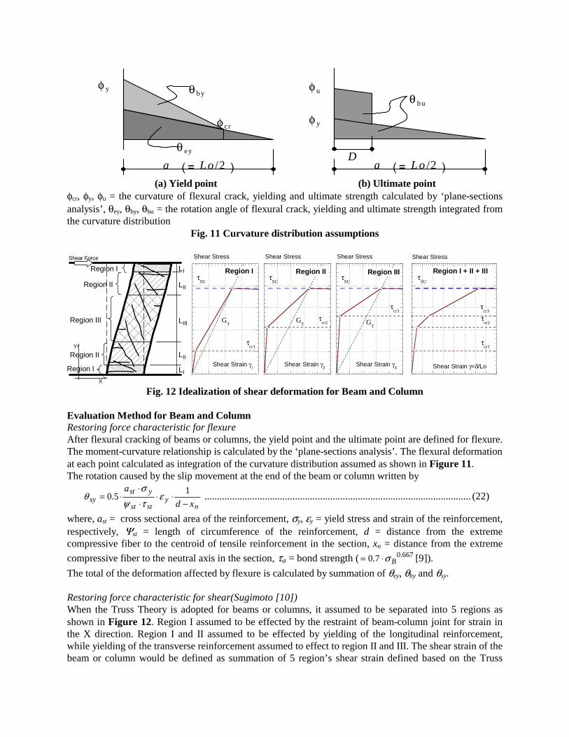
(a) Yield point (b) Ultimate point φcr, φy, φu = the curvature of flexural crack, yielding and ultimate strength calculated by ‘plane-sections analysis’, θey, θby, θbu = the rotation angle of flexural crack, yielding and ultimate strength integrated from the curvature distribution
Fig. 11 Curvature distribution assumptions
Region I
Region II
Region III
Region II
Region I LI
LIII
LII
LII
LI
Y
X
Shear Force
Region I
Shear Stress
Shear Strain γ1
τcr1
τSU
GT
Region II
Shear Stress
Shear Strain γ2
τcr2
τSU
GT
Region III
Shear Stress
Shear Strain γ3
τcr3
τSU
GT
Region I + II + III
Shear Stress
Shear Strain γ=δ/Lo
τcr3
τcr2
τcr1
τSU
Fig. 12 Idealization of shear deformation for Beam and Column
Evaluation Method for Beam and Column Restoring force characteristic for flexure After flexural cracking of beams or columns, the yield point and the ultimate point are defined for flexure. The moment-curvature relationship is calculated by the ‘plane-sections analysis’. The flexural deformation at each point calculated as integration of the curvature distribution assumed as shown in Figure 11. The rotation caused by the slip movement at the end of the beam or column written by
ny
stst
ystsy xd
a
−⋅⋅
⋅
⋅⋅= 1
5.0 ετψσ
θ .......................................................................................................... (22)
where, ast = cross sectional area of the reinforcement, σy, εy = yield stress and strain of the reinforcement, respectively, Ψst = length of circumference of the reinforcement, d = distance from the extreme compressive fiber to the centroid of tensile reinforcement in the section, xn = distance from the extreme
compressive fiber to the neutral axis in the section, τst = bond strength ( 667.07.0 Bσ⋅= [9]).
The total of the deformation affected by flexure is calculated by summation of θey, θby and θsy. Restoring force characteristic for shear(Sugimoto [10]) When the Truss Theory is adopted for beams or columns, it assumed to be separated into 5 regions as shown in Figure 12. Region I assumed to be effected by the restraint of beam-column joint for strain in the X direction. Region I and II assumed to be effected by yielding of the longitudinal reinforcement, while yielding of the transverse reinforcement assumed to effect to region II and III. The shear strain of the beam or column would be defined as summation of 5 region’s shear strain defined based on the Truss

Theory. The previous expressions from Eq.(4) to Eq. (9) can be adopted to calculate the shear stress-strain relationship for each region, basically. Only for region I, 1/KX=0 is assumed. For region II and III, to consider the influence of cover concrete, Eq.(7) is changed into following expression;
)384
1(1
4
eco
r
sXXX jIEc
bs
EpK
⋅⋅⋅⋅+
⋅= ............................................................................................. (23)
where, s = spacing of the transverse reinforcement, br = spacing of the longitudinal reinforcements hooked by the transverse reinforcement, je = maximum distance between compressive and tensile reinforcement,
Cs = thickness of cover concrete. Ico = moment of inertia of cover concrete (= 128 3Css ⋅⋅ ) For columns, to consider the influence of the axial force, Eq.(8) is changed into following expression;
0
000 )(
y
yYOY
KK
εεεσ −⋅+
= ............................................................................................................... (24)
where, )/,0.1min(, 0 VmyVsuEpK yysYyYO ⋅=⋅= εε , σ0, ε0 = average axial stress and strain over entire cross
sectional area, respectively, εy = yield strain of the longitudinal reinforcement, Vsu = shear strength of the column, Vmy = flexural yielding strength of the column. The idealization of the shear stress-strain relationship is shown in Figure 13. For shear failure mode, the 3rd point is defined as the ultimate shear strength (τU). At this point, it is assumed as following; 1) The concrete stress declines to 80% of the maximum compressive strength because of stress softening. 2) The stress of the transverse reinforcement reaches at 110% of the yield stress and the strain reaches at approximately 10000µ because of the strain hardening. The Truss Stiffness GMU in Figure 13(b) is calculated by the assumption that the Young’s modulus of the steel EsY in Eq.(24) is reduced as 1% of the elastic stiffness for region I and II. Evaluation of crack width Minimum of the shear crack spacing sLcr.min is calculated by the following expression, which modified for beams or columns from the proposition by Adachi [5]. And maximum of the shear crack spacing sLcr.max is defined as twice of sLcr.min.
yyxx
cewTcrs
tbL
φτφτσ
⋅+⋅⋅⋅⋅= 2
min. ................................................................................................................ (25)
where, σT = tensile strength of the concrete(= Bσ⋅33.0 ), bew = equivalent width(= θθ cossin ⋅+⋅ YX SS ), tc =
twice as the thickness of cover concrete, τx, τy = bond strength of the longitudinal and the transverse reinforcement, respectively( 67.0)/1(7.0 BBo σσσ ⋅+⋅= , 67.07.0 Bσ⋅= ), SX, SY = average spacing of the longitudinal and the transverse reinforcement, respectively. The principal tensile strain ε1 is function of the shear strain γ and the Truss Stiffness GT, as written by
γθθθθε ⋅⋅⋅⋅+⋅+= TYX GKKK )]sincos(1)tan(1tan[ 21 ................................................................. (26) Verification by loading test for beams and columns Outline of loading test 1 beam of about 1/2 scale and 2 columns of about 2/3 and full scale were tested. The dimensions and the reinforcement of the beam test specimen is shown in Figure 14, and the dimensions and the test setup of the column test specimens are shown in Figure 15. The properties of the test specimens are given in Table 1. The material properties are given in the table, also. The beam specimen F-L was simply supported at each end of the stab, and was subjected to anti-symmetric bending moment reversals in the span length of 2 meters. The column specimens were subjected to constant axial force and anti-symmetric bending moment reversals by lateral force making the top and the bottom stab parallel.

GTSU
GTU
sτcr
sτSU
sτU
γ1 γ2 γ3
γ
τ
GTSU
GMU
sτcr
sτSU
sτMU
sτMY
γ1 γ2 γ3
γ
τ
(a) Shear Failure Mode (b) Flexural Yielding before Shear Failure τSU = maximum shear stress of shear failure mode , τU = ultimate shear stress, τMY = shear stress at flexural yielding, τMU = ultimate shear stress after flexural yielding
Fig. 13 Idealization of shear stress-shear strain relationship for beam or column
Table 1 Properties of test specimen for the verification
Specimen F-L S13-N
(2/3 scale) S13-N-R
(full scale)
Section 2-D25
4-D25
4-D10
12-D25
-D13
16-D32
-D13 B X D [mm X mm] 350 X 400 470 X 470 700 X 700
Height or Length [mm] 2000 1410 2100
Longitudinal Reinforcement 6-D25 (Top/Bottom) 12-D25 16-D32
Material Properties σy / Es [N/mm2]
507 / 1.96 X10⁵ 1006 / 1.94 X10⁵ 1014 / 1.96 X10⁵
Transverse Reinforcement 4-D10@60 4-D13@140 4-D13@100
Material Properties σwy / Eh [N/mm2]
825 / 2.09 X10⁵ 337 / 1.89 X10⁵ 337 / 1.89 X10⁵
Concrete Properties σB / Ec [N/mm2]
25.8 / 2.51 X10⁴ 40.2 / 2.70 X10⁴ 42.4 / 2.99 X10⁴
Axial Force [kN] 0 1292 2867
σy, Es: observed yield stress and Young’s modulus of longitudinal reinforcement, σwy, Eh: observed yield stress and Young’s modulus of transverse reinforcement, σB, Ec: observed compressive strength and Young’s modulus of concrete
Test results and verification Figure 16 shows the comparison of the observed and the calculated restoring force characteristics and the shear crack width-deformation relationship of the beam specimen F-L. The observation is shown only envelope of the positive direction. It was observed that the first yielding of the longitudinal reinforcement

occurred when the deformation reached 19 mm. The calculated final point, the deformation was about 36mm, was derived from the assumption that the strain of the extreme compressive fiber in the section (εcu) reached 3000 µ for the flexural analysis. The result of the other case of analysis, which was assumed as εcu = 10000 µ, was plotted in the same figure. It is difficult to define εcu for calculating the ultimate deformation after yielding. For practical design, the assumption of εcu = 3000 µ gives underestimation of ultimate deformation. The calculations are correspondent with the experimental results very well for both of the restoring force characteristics and the crack width. Figure 17 and Figure 18 shows the comparison of the observed and the calculated restoring force characteristics and shear crack width-shear displacement relationship of the test specimen S13-N and S13-N-R, respectively. Both specimens were failed by shear before yielding of the longitudinal reinforcement. Though the transverse reinforcement ratio is about 0.7% for both specimens, the size of the specimen S13-N-R was about 1.5 times as that of the specimen S13-N. The calculations are corresponded well to the experimental results, in spite of the difference of their sizes.
2,0002001,300250
1,7502501,300200
1,750
4-D252-D25
4-D10@60mmPositive Loading
Negative Loading
Stab
L1 L1L0
d: DeformationP: Load
P: Load
Q: Shear ForceQ = P(L1+L1)/(L1+L0+L1)
(a) Dimensions and reinforcement of beam test specimen (b) Definition of force and deformation
Fig. 14 Outline of the beam test
565 470 5651,600
12-D25
D13@140mm
3600 1950
3650
2150
SPECIMEN
2500kNActuator
4000kNActuator
4000kNActuator
Lateral LoadAxialForce
AxialForce
1600
470
(a) Specimen S13-N (b) Test setup
Fig. 15 Outline of the column test

0
100
200
300
400
500
600
0 20 40 60 80 100 120
Specimen F-L
Exp.(Total)Cal.(Total,10000µ)Cal.(Total, 3000µ)Exp.(Shear)Cal.(Shear,10000µ)Cal.(Shear, 3000µ)
Shear Force [kN]
Deformation [mm]
0.00
0.50
1.00
1.50
2.00
0 5 10 15 20
Specimen F-LObservedCalculation(10000µ)Calculation(3000µ)
Crack width [mm]
Shear deformation [mm]
(a) Shear force-deformation relationship (b) Crack width
Fig. 16 Comparison of observed and calculated result for Specimen F-L
0
200
400
600
800
1000
1200
0 5 10 15 20 25 30
Specimen S13-N
Exp.(Total)Cal.(Total)Exp.(Shear)Cal.(Shear)
Shear force [kN]
Lateral displacement [mm]
0.00
0.50
1.00
1.50
2.00
2.50
3.00
0 2 4 6 8 10 12
Specimen S13-N
Observed
Calculation
Crack width [mm]
Shear Displacement [mm]
(a) Lateral load-displacement relationship (b) Crack width
Fig. 17 Comparison of observed and calculated result for Specimen S13-N
0
500
1000
1500
2000
2500
0 5 10 15 20 25 30 35 40 45
Specimen S13-N-R
Exp.(Total)Cal.(Total)Exp.(Shear)Cal.(Shear)
Shear force [kN]
Lateral displacement [mm]
0.00
0.50
1.00
1.50
2.00
2.50
3.00
0 2 4 6 8 10 12 14 16 18
Specimen S13-N-R
ObservedCalculation
Crack width [mm]
Shear Displacement [mm]
(a) Lateral load-displacement relationship (b) Crack width
Fig. 18 Comparison of observed and calculated result for Specimen S13-N-R
EXAMPLE OF DESIGN PROCESS FOR RC STRUCTURE Analytical Model The evaluation methods proposed in the previous sections were installed into three-dimensional inelastic frame analysis program “DREAM-3D”(Nagahara [11]) which was originally developed. In this program, the multi spring model (Lai [12]) is used for the flexural deformation of walls and columns. For beams and the shear deformation of walls and columns, the program was modified to adopt the proposed methods. A six-story RC wall-frame structure was studied for example using the program “DREAM-3D”. The outline of the analytical process will be described in this section.

Figure 19 shows the plan and the sectional elevation of the RC structure designed for example. It was designed as a six-story office building in the guidelines [13]. Design Process The design process is based on the design procedure proposed in the guidelines [1]. This procedure would be applied to the structure, which was completed normal structural design. 1) Nonlinear static analysis under monotonically increasing horizontal forces “pushover analysis”, is carried out. 2) Each limit state is defined based on the damages of the members consisted in the structure. 3) Nonlinear earthquake response analysis of multi-degree of freedom system is carried out. Calculation of Limit State Three limit states of the structure are defined as follows, Limit State of Serviceability, Limit State of Reparability (or limit state of damage control) and Limit State of Safety. Limit State of Reparability could be classified into two levels; i.e., minor or medium damage and major damage. This classification should be determined in consideration of the requirement of repair. Table 2 shows each limit state and correspondent image of the damage. The limit state of each story was derived from the damages of members consisted in each story. Figure 20 shows the relationship between story shear force-story drift as a result of calculation and each limit state defined based on the damages of consisting members. Response Analysis of Multi-degree of Freedom System The story shear force-story drift relationships were idealized into tri-linear curves for the response analysis. The idealizations were shown in Figure 20, also. The Takeda model (Takeda [14]) was selected for the hysteresis model. Ordinary earthquake acceleration record of NS component of Hachinohe(1968) was used to carry out the response analysis. 2 cases were conducted for standardized waves of the maximum velocity as 250mm/sec and 500mm/sec. The example of damage evaluation is shown in Figure 21, which was drawn by post-process of “DREAM-3D”. In this case, each story response was less than the Limit State of Reparability II. It means that the residual crack width as the maximum damage of the members after the earthquake was less than 2.0mm.
6,000 6,000 6,000 6,000 6,000 6,00036,000
X1 X2 X3 X4 X5 X6 X7
Y1
Y2
Y3
Y4
6FL
RFL
5FL
4FL
3FL
2FL
1FL
Multi-Story Wall
Y2Y1 Y3 Y4
9,0009,000 8,00026,000
(a) Floor plan (b) Typical elevation (X4 Axis)
Fig. 19 Example structure ([13])

Table 2 Limit states and damages I) Limit State of Serviceability
rWcr: Less than 0.2mm Repair: Unnecessary
III) Limit State of Reparability II ( Major Damage )
rWcr: Less than 2.0mm Repair: (ex.) Concrete casting
II) Limit State of Reparability I ( Minor or Medium Damage )
rWcr: Less than 1.0mm Repair: (ex.) Epoxy injection
IV) Limit State of Safety
rWcr: Over 2.0mm Repair: Impossible
rWcr = residual crack width after earthquake
0
8000
16000
24000
32000
0 2 4 6 8 10 12 14 16
Story shear force [kN]
Story drift [mm]
1st floor
2nd floor
3rd floor
4th floor
5th floor
6th floor
limit state IIIlimit state II
limit state I
HACH(NS) 50kine
HACH(NS) 25kine
Fig. 20 Story shear force-story drift relationship Fig. 21 Example of damage evaluation
CONCLUSIONS For the performance based design process, the damage evaluation methods for earthquake resistant reinforced concrete members were developed and proposed in this paper. The special features of the proposed methods were following; 1) The shear stress-strain relationship assumed to be degraded its stiffness not only at cracking of the
concrete but also at yielding of the reinforcement. 2) The shear stiffness after crack formed was calculated based on the truss theory. 3) The shear crack width was calculated as the product of the crack spacing and principal tensile strain
derived from the Truss Theory. The proposed methods were verified its correspondence with accurate behavior by wall, beam and column tests. The restoring force characteristics and the crack width-displacement relationship calculated by the proposed methods corresponded well to the experimental results. The calculation procedures were installed into the original program ”DREAM-3D”. For the example of the design process, a six-story RC building were analyzed by using the program.

REFERENCES 1. “Guidelines for Performance Evaluation of Earthquake Resistant Reinforced Concrete Buildings
(Draft)”, Architectural Institute of Japan, 2004 2. Kazuaki TSUDA, “Evaluation Method for Relationship between Shear Force and Deformation of
Shear Walls (Part 1: Evaluation Method for Relationship between Shear Stress and Shear Strain of Shear Panels)”, Journal of Structural and Construction Engineering, 1999.3, No.517, pp.125-132
3. Kazuaki TSUDA and Hiroaki ETO, “A Study on the Evaluation Method for the Earthquake Resistant Performance of the Reinforced Concrete Multi-story Shear Walls (Part 1: Evaluation Method for the Restoring Force Characteristic of the Reinforced Concrete Multi-story Shear Walls)”, Journal of Structural and Construction Engineering, 2003.7, No.569, pp.97-104
4. Kazuaki TSUDA, Kuniyoshi SUGIMOTO and Hiroaki ETO, “A Study on the Evaluation Method for the Earthquake Resistant Performance of the Reinforced Concrete Multi-story Shear Walls (Part 2: Evaluation Method for the Flexural and Shear Crack Width of the Reinforced Concrete Multi-story Shear Walls)”, Journal of Structural and Construction Engineering, 2004.1, No.575, pp.97-104
5. Hiromi ADACHI, Arata ONO, Mitsukazu NAKANISHI and Yoichi MINAMI, “Mechanism of Shear Crack Formation in Reinforced Concrete Shear Walls”, Proceedings of the Japan Concrete Institute, 1981, Vol. 3, pp.469-472
6. Kazuyuki MATSUMOTO and Toshimi KABEYASAWA, “Experimental Study on Elast-Plastic Behaviors of Reinforced Concrete Framed Shear Walls”, Proceedings of the Japan Concrete Institute, 1990.6, Vol. 12, No. 2, pp.545-550
7. Toshio. SATO, “A Study on the Elasto-Plastic Characteristics of Reinforced Concrete Earthquake Resistant Wall (Part 10) ”, Summaries of Technical Papers of Annual Meeting Architectural Institute of Japan, 1980.9, pp.1625-1626
8. Toshio SHIGA, Akenori SHIBATA, Junichi TAKAHASHI, Yuhiko SUGITA and Toshimi MOGAMI, “Experiments on Seismic Behavior and Repair Techniques of Reinforced Concrete Flexural Yielding Shear Walls”, Summaries of Technical Papers of Annual Meeting Architectural Institute of Japan, 1983.9, pp.2175-2180
9. “Design Guidelines for Earthquake Resistant Reinforced Concrete Buildings Based on Inelastic Displacement Concept”, Architectural Institute of Japan, 1999
10. Kuniyoshi SUGIMOTO, “An Evaluation Method for Restoring Force Characteristics of Reinforced Concrete Columns and Beams( Evaluation of skeleton curve in consideration of nonlinear behavior of shear deformation)”, Journal of Structural and Construction Engineering, 2004.4, No.578, pp.123-130
11. Katsumi NAGAHARA, Kenzo YOSHIOKA and Hiroaki ETO, “Three-dimensional Nonlinear Seismic Response Frame Analysis of Reinforced Concrete Highrise Buildings”, International Conference on TALL BUILDINGS “REACH FOR THE SKY”, 1992.7, pp.169-176
12. Shing-Sham LAI, George T. WILL and Shunsuke OTANI, “ Model for Inelastic Biaxial Bending of Concrete Members”, Journal of Structural Engineering, Proceedings of the American Society of Civil Engineers, 1984.11,Vol.110, No.11, pp.2563-2584
13. “Design Guidelines for Earthquake Resistant Reinforced Concrete Buildings Based on Ultimate Strength Concept” , Architectural Institute of Japan, 1990
14. Toshikazu TAKEDA, Mete A. Sozen and N. Norby Nielsen, “ Reinforced Concrete Response to Simulated Earthquakes”, Journal of the Structural Division, Proceedings of the American Society of Civil Engineers, 1970.12, Vol.96, No.ST12, pp.2557-2573