performance evaluation of heat exchangers for … · performance evaluation of heat exchangers for...
TRANSCRIPT

Performance Evaluation of Heat Exchangers for Application to Ocean Thermal Energy Conversion System
Takeshi YASUNAGA*1, Kevin FONTAINE*2,3, Takafumi MORISAKI*1 and Yasuyuki IKEGAMI*1
*1 Institute of Ocean Energy, Saga University1-honjo, Saga-shi, Saga, 840-8502, Japan
*2 Master of Physics, Phelma graduate school of Engineering3 Parvis Louis Neel – CS 50257, 38016 Grenoble Cedex 01, France
*3 EPF, graduate school of Engineering3 bis Rue Lakanal, 92330 Sceaux, France
Abstract Ocean thermal energy conversion (OTEC) is a system to convert the ocean thermal energy, which is stored
as the vertical temperature gradient in the ocean, into the electricity and the heat exchanger performance is significantly important. Theoretical maximum power output and the relationship between heat exchanger performances have been formulated in finite-time thermodynamics. And considering the seawater intake pumping powers in OTEC system, the thermal efficiency in case of the maximum net power has shown by introducing the ideal heat exchanges from heat source to heat engine. Considering the OTEC system without seawater intake system, the required pumping power of surface and deep seawaters will be the same magnitude of power as the generated power in the heat engine, and they might be able to get over the generated power due to the balance of the heat transfer performance and pressure drop in the heat exchangers. For each heat exchangers, heat transfer performance and pressure drop can be measured and summarized. However, for the application of the OTEC as an evaporator and a condenser, the effect of both characteristics on the net power in OTEC are same magnitude and very important. Therefore, the total performance evaluation method of heat exchangers is required for the selection and design of the heat exchangers as well as the development of the heat exchanger performance. This study describes about the theoretical relationship between heat transfer performance of heat exchangers including pressure drop and power output from the heat engine and shows the results of the comparison of the available power output from the power generation system using existing 3 plate heat exchangers (PHEs).
Key words : OTEC, Heat Exchanger Performance index, Maximum Power, Optimization Method, Optimum Function, Power output maximization, Plate heat exchanger
1. Introduction Ocean thermal energy conversion (OTEC) is a system to convert the ocean thermal energy, which is stored as the
vertical temperature gradient in the ocean, into the electricity. Thermal efficiency of OTEC is theoretically low due to quite low available temperature difference between heat sources, and thus, an abundant heat source quantity is required compared to conventional power plants. In closed cycle OTEC system, the heat exchangers are applied as an evaporator and a condenser to transfer the thermal energy between the heat sources and the engine (Uehara, 1982, Avery and Wu, 1994). In general, since the system uses the thermal energy stored as the sensible heat of seawater, harnessing the thermal energy from heat source yields the change of the heat source temperature, this temperature change causes the reduction of the available temperature difference for the heat engine, which declines the thermal efficiency of heat engine, then theoretical maximum power output is formulated in finite-time thermodynamics (Ibrahim, 1992 and Bejan, 1998).. Ikegami and Bejan (1998) consider the seawater intake pumping powers in OTEC system by using the ideal heat engine,
* Date of Manuscript Acceptance: 2017. 8.10E-mail of corresponding author: [email protected]
65Performance Evaluation of Heat Exchangers for Applicationto Ocean Thermal Energy Conversion System
OTECVol. 22 (2017),65〜75

2. NomenclatureA : heat transfer area (m2)BWR: backwork ratio (-)C : heat capacity flow rate (W/K)cp : specific heat (J/kgK)Deq : equivalent diameter (m)f : friction factor (-)
: mass flow rate (kg/s)NTU : number of transfer unit (-)Q: heat transfer rate (W)r : ratio of warm seawater heat capacity flow rate (-)S : total cross sectional area in PHE (m2)T : Temperature (K), (oC)Tm : logarithmic Temperature (K)U : overall heat transfer coefficient (W/m2K)v : mean velocity in the plate (m/s)W: power output (W)P: pumping power (W)
Greek symbols : Heat transfer coefficient (W/m2K)
: Density (kg/m3) : Thermal conductivity (W/mK) : kinetic viscosity coefficient (m2/s) : Efficiency (W/mK) : Performance index for OTEC heat exchanger (-)
Subscripts C : cold deep seawater H : high heat working temperature in irreversible heat engine HS : heat source L : low heat working temperature in irreversible heat engine m : maximized NTU : considered the number of transfer unit O : outlet of heat exchanger P : pump pt : plate W : warm surface seawater
introduce the ideal heat exchange from heat source to heat engine, and show the thermal efficiency in case of the maximum net power. Considering the OTEC system without seawater intake system, the required pumping power of surface and deep seawaters will be the same magnitude of power as the generated power by the heat engine, and they might be able to get over the generated power due to the balance of the heat transfer performance and pressure drop in the heat exchangers (Yasunaga, et al., 2008). To achieve the development of the net power output from OTEC system, the ideal practical heat exchanger is required, which has enhanced heat transfer performance and low pressure drop. On the other hand, the performance evaluation of the heat exchangers is generally conducted to evaluate the heat transfer performance and pressure drop produced by friction. For each heat exchangers, heat transfer performance and pressure drop can be measured and summarized. So, the individual comparison of heat exchanger performance considering heat transfer performances or pressure drop is definitely obtained. However, in the case of an OTEC system in which heat exchangers are used as evaporator and condenser, both characteristics have an important effect on the net power output and are of the same magnitude.
Therefore, the total performance evaluation method of heat exchangers is required for the selection and design of the heat exchangers as well as the development of the heat exchanger performance. This study describes about the theoretical relationship between heat transfer performance of heat exchangers including pressure drop and power output from the heat engine and shows the results of the comparison of the available power output from the power generation system using existing heat exchangers.
3. Fundamental Equations3.1 Principle of OTEC systemFig.1 shows the OTEC power generation system model using reversible heat engine. The ocean thermal energy is thetemperature difference between the surface seawater and the depth. To harvest the thermal energy, both seawaters shouldbe continuously flowed to the heat exchangers to transfer the heat to with the heat engine by heat exchangers. The poweroutput from heat engine W, heat transfer rate from warm seawater QW and to the cold deep seawater QC are, respectively,
(1) (2)
(3)
Takeshi YASUNAGA, Kevin FONTAINE, Takafumi MORISAKI and Yasuyuki IKEGAMI66
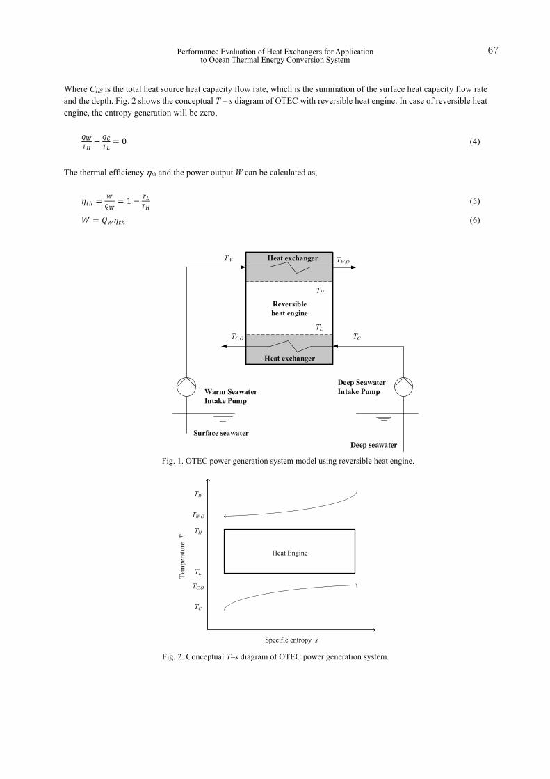
Where CHS is the total heat source heat capacity flow rate, which is the summation of the surface heat capacity flow rate and the depth. Fig. 2 shows the conceptual T – s diagram of OTEC with reversible heat engine. In case of reversible heat engine, the entropy generation will be zero,
(4)
The thermal efficiency th and the power output W can be calculated as,
(5)
(6)
Fig. 1. OTEC power generation system model using reversible heat engine.
Fig. 2. Conceptual T–s diagram of OTEC power generation system.
Warm SeawaterIntake Pump
Deep SeawaterIntake Pump
Surface seawaterDeep seawater
Heat exchanger
Heat exchanger
Reversibleheat engine
TW,O
TC,O TC
TW
TL
TH
Heat Engine
Tem
pera
ture
T
Specific entropy s
TH
TL
TW,O
TW
TC
TC,O
Performance Evaluation of Heat Exchangers for Applicationto Ocean Thermal Energy Conversion System
67

3.2 Heat exchanger performance for OTEC power output In heat exchange process, heat exchangers are used and the heat flow rate depends on the performance of the heat exchangers. Using overall heat transfer coefficient U and logarithmic mean temperature Tm, the heat transfer rates can be expressed as,
�� � ���������� (7)�� � ���������� (8)
From Eq.(1) to (6), the work output can be the one degree of freedom as function of TW,O or TC,O. Then the work output can be maximized by �� �����⁄ � � or �� �����⁄ � � . The maximum work considering the heat exchanger performance Wm,NTU can be expressed as,
������ � �������������� (9)
Here,
� � ����������� � �
�������� (10)
����� � ���� � ���� (11)
Where, NTU is the heat transfer unit and is defined as follows;
��� � ���� �� (12)
If NTU is infinite, the maximum power output Eq.(9) will be as follows,
�� � ��� � ��������� (13)
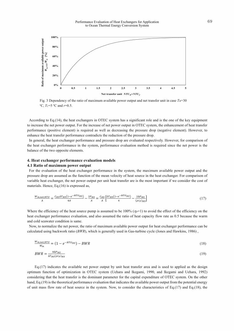
Fig.3 shows the relationship between the ratio of maximum available power output Wm,NTU / Wm and the heat transfer performance as net transfer unit NTUW and NTUC. According to Fig.3, the ratio of maximum available power will be 63%, 86% and 95% when NTU is 1.0, 2.0 and 3.0, respectively.
In the OTEC system, the pressure drop due to the friction of the stream in the heat exchanger is not negligible. The pressure drop yields the pumping power for the seawaters, which can be calculated as,
� � �� ����� (14)
Where P is the mechanical efficiency of the seawater pumps and simplified P can be the pressure drop of the heat exchangers. The total pressure drop in the stream of the seawaters is related the friction factors of the each heat exchangers, piping, valves and the mean velocities in the each equipment. Then, the net power output is calculated as,
���� � � � ��� � ��� (15)
Then, the maximum net power using reversible heat engine will be,
���������� � �������������� � ��� � ��� (16)
Takeshi YASUNAGA, Kevin FONTAINE, Takafumi MORISAKI and Yasuyuki IKEGAMI68
According to Eq.(14), the heat exchangers in OTEC system has a significant role and is the one of the key equipment to increase the net power output. For the increase of net power output in OTEC system, the enhancement of heat transfer performance (positive element) is required as well as decreasing the pressure drop (negative element). However, to enhance the heat transfer performance contradicts the reduction of the pressure drop. In general, the heat exchanger performance and pressure drop are evaluated respectively. However, for comparison of
the heat exchanger performance in the system, performance evaluation method is required since the net power is the balance of the two opposite elements.
4. Heat exchanger performance evaluation models4.1 Ratio of maximum power outputFor the evaluation of the heat exchanger performance in the system, the maximum available power output and the
pressure drop are assumed as the function of the mean velocity of heat source in the heat exchanger. For comparison ofvariable heat exchanger, the net power output per unit heat transfer are is the most important if we consider the cost ofmaterials. Hence, Eq.(16) is expressed as,
����������� � ������������������
�� � ����� � ���
� ����������������� � ������������� (17)
Where the efficiency of the heat source pump is assumed to be 100% (P=1) to avoid the effect of the efficiency on the heat exchanger performance evaluation, and also assumed the ratio of heat capacity flow rate as 0.5 because the warm and cold seawater condition is same. Now, to normalize the net power, the ratio of maximum available power output for heat exchanger performance can be
calculated using backwork ratio (BWR), which is generally used in Gas-turbine cycle (Jones and Hawkins, 1986) ,
������������ � �� � �������� � ��� (18)
��� � ���������������� (19)
Eq.(17) indicates the available net power output by unit heat transfer area and is used to applied as the design optimum function of optimization in OTEC system (Uehara and Ikegami, 1990, and Ikegami and Uehara, 1992) considering that the heat transfer is the dominant parameter for the capital expenditure of OTEC system. On the other hand, Eq.(19) is the theoretical performance evaluation that indicates the available power output from the potential energy of unit mass flow rate of heat source in the system. Now, to consider the characteristics of Eq.(17) and Eq.(18), the
0%
20%
40%
60%
80%
100%
0 0.5 1 1.5 2 2.5 3 3.5 4 4.5 5
Ratio
of m
axim
um av
aila
ble p
ower
outp
utW
m,NTU/W
m[%
]
Net transfer unit NTUW=NTUC
Fig. 3 Dependency of the ratio of maximum available power output and net transfer unit in case TW=30 oC, TC=5 oC and r=0.5.
Performance Evaluation of Heat Exchangers for Applicationto Ocean Thermal Energy Conversion System
69

following performance index for OTEC heat exchanger is proposed,
� � ������������� � ���������������
� (20)
3.2 Optimization of maximum power The heat transfer performance UA is expressed as,
�� � 11
���� ��
���� �1��� �
���
(21)
Taking the assumption that the heat resistance of the heat source heat transfer coefficient is dominant,
1���� �
����� �
1��� �
��� � 1
���� � � �22�
�� � ������λ � �Re�Pr�� �2��
Where, Nu, Re and Pr are Nusselt, Reynolds and Prandtl numbers, respectively. Hence, Eq.(21) can be expressed as,
�� � ��
������� ������
����
���������������
(24)
With the following definitions:
�� � ρ���Pr � μ��λ � Re � ρ����
μ (25)
�� �� � ����� � RePr��� (26)
Therefore, NTU can be calculated as,
��� � �Re�Pr��λA���� � ��Re�Pr��λA�����λ����
� �Re���Pr����������� � ��Re�Pr��λA��
(27)
The seawater pumping power at the warm and cold side respectively which depend of the pressure loss in the heat exchangers.
�� � 4�����
ρv�2
(28)
With (25) and (28)
� � ����ρ � 4�������2���� � 2��Re����
���� ��(29)
� � �Re� (30)
Takeshi YASUNAGA, Kevin FONTAINE, Takafumi MORISAKI and Yasuyuki IKEGAMI70

Finally, with (9) to (11) and (27) to (29),
��m,net,NTU � �����
���������� �����������
� ����������� ����������
�
� �������������� �� ��� �������������� �� �
� (31)
The Matlab function “fminsearch” is used. It is an optimization algorithm based on a derivative-free method (Nelder-Mead simplex algorithm) to find a local minimum to a function. However, “fminsearch” does not allow the user to add constraints nor boundaries for the parameters. Thus the function “minimize” written by Rody Oldenhuis (2017) is used instead. It is based on Matlab “fminsearch” algorithm and allows constraints and boundaries. This function need, as input, the function to minimize, a starting point (values of the parameters where the algorithm starts to search for a local minimum), linear inequality constraints, linear equality constraints, lower boundary, upper boundary and nonlinear inequality and equality constraints. In this case only nonlinear constraints and boundaries will be used.
As the function is designed to find a local minimum, the function Wnet,net,NTU is minimized. Moreover, the function needs to be used several times at random starting points within the boundaries in order to search for a global maximum.
5. Results and discussions5.1 Ratio of maximum power output
As one of the example of the evaluation using the ratio of maximum power output, 3 different plate type heat exchangers are used (Kushibe, et al., 2005). Table 1 shows the heat exchanger specifications. By referring the performance date on the paper, each overall heat transfer performance and pressure drop are approximated as the function of the mean velocity of heat source in the exchangers. The approximation coefficients are listed on the Table 2.
Figure 4 shows the net power output per unit heat transfer area as function of the mean velocity of heat source in the plate. In each PHE, the maximum power output per unit area forms a parabolic path. The maximum power output is a balance of the increase of maximum power and the heat source pumping power. The NTU increases with the increase of the mean velocity of heat source, however, the increase of the pressure drop is higher than the maximum power output, then as a results, the net power output will be form the parabolic curve. The optimum heat source mean velocities are 0.30, 0.47 and 0.39 for PHE1, PHE2 and PHE3, respectively. In case PHE2, the optimum heat source mean velocity is over the range of the overall heat transfer coefficient experimental data and then the calculation was assumed that the 0.40 m/s to 0.59 m/s will varies the same trend as the experimental date range.
The parameters of the optimum mean heat source velocity is listed in Table 3. And Fig. 5 shows the ratio of the net power output, backwork ratio and ratio of other losses during the heat exchange process. According to Table 3 and Fig.5, the performance of PHE1 is highest ratio of the net power output of 60%, and PHE3 follows that of 52% and in case of PHE2 is only 41%. The results shows that PHE2 is the lowest NTU at the optimum heat source mean velocity rather than that of PHE1 and PHE3. This means that the system applied PHE2 is the highest heat source consumer. On the other hand, with regard to BRW, PHE2 is the lowest compare with the other two PHEs. Regarding the performance index for OTEC heat exchanger , PHE2 is almost triple of both PHE1 and PHE3. From Eq.(13), the maximum power output is proportional to the mass flow rate of the heat source, in PHE2 is the best overall performance.
5.2 Optimized maximum power evaluation Calculations are done with a Reynolds number taken so that the water velocity in the heat exchangers is between 0.2 m/s and 1.8 m/s. Wnet/A is calculated and plotted as a function of Rews and Recs. This calculation is limited to the Reynolds boundary specified. Axis are set so that only Wm,net,NTU corresponding to reachable Reynolds is displayed. For each heat exchangers the Nusselt correlation and friction factor are used. These values are given in the table 4. And Fig. 6 to 8 show Wm,net,NTU as a function of Reynolds number for PHE1, PHE2 and PHE3 in case of TW=30 oC and TC=5 oC. Actual power output of an OTEC power plant using the specified heat exchanger should be less than these results as calculations are based on a Carnot cycle and if pressure drop is considered, required power for water ducting is not. However, results give the optimum Reynolds numbers and show that, for a non-negligible range of Reynolds number, net power output can be null or negative (dark blue areas). Flow rate should then be controlled rigorously to adjust Reynolds number in the heat exchanger.
Performance Evaluation of Heat Exchangers for Applicationto Ocean Thermal Energy Conversion System
71

Table 1 Heat exchangers specifications. Heat exchanger PHE1 PHE2 PHE3 Length (mm) 960 718 1765 Width (mm) 576 325 605
Plate Thickness (mm) 0.7 0.5 0.6 Space between plates (mm) 4 3.96 2.68 equivalent diameter (mm) 8 7.9 5.36
Material SUS316 Titanium titanium Surface pattern Herringbone (72°) Herringbone (30°) Fluting & drainage
Number of plates 120 20 52 Total heat transfer area(m²) 100.3 3.96 40.6
Total cross surface area (m²)
0.14 0.012 0.041
Table 2 Approximation coefficients.
Heat exchanger PHE1 PHE PHE3
Overall heat transfer coefficient U (kW/m2K)
Multiplier factor 4.197 5.637 3.254 Exponential factor 0.223 0.359 0.456
Data range VHS 0.20-0.44 0.59-1.20 0.29-0.59
Pressure drop P (kPa) Multiplier factor 306.31 65.38 182.30
Exponential factor 1.863 2.210 2.004 Data range VHS 0.16-0.45 0.60-0.19 0.48-0.59
*The data is approximated as an exponential function as U= VHS and P = VHS
Fig. 4 The net power output per unit heat transfer area as function of the mean velocity of heat source in the plate. In case the TW=30 oC, TC=5 oC, cp=4.0 kJ/kgK and =1,025 kg/m3.The chain line in PHE2 shows the extended from experimental range. The circular plots show the maximum point of power output and i.e. the optimum mean velocity of heat source in each plate heat exchanger.
Takeshi YASUNAGA, Kevin FONTAINE, Takafumi MORISAKI and Yasuyuki IKEGAMI72
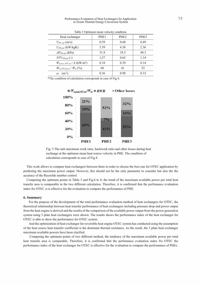
Table 3 Optimum mean velocity condition. Heat exchanger PHE1 PHE2 PHE3
VHS, opt (m/s) 0.39 0.60 0.49 UHS,opt (kW/kgK) 3.39 4.58 2.36 PHS,opt (kPa) 51.8 18.3 44.3 NTUHS,opt (-) 1,57 0.65 1.14 Wm,net, NTU,m / A (kW/m2) 0.18 0.39 0.14 Wm,NTUnet,m / Wm (%) 60 41 52 (m-2) 0.36 0.98 0.33
*The condition of calculation corresponds in case of Fig.4.
Fig. 5 The unit maximum work ratio, backwork ratio and other losses during heat exchange at the optimum mean heat source velocity in PHE. The condition of calculation corresponds in case of Fig.4.
This work allows to compare heat exchangers between them in order to choose the best one for OTEC application by predicting the maximum power output. However, this should not be the only parameter to consider but also the the accuracy of the Reynolds number control.
Comparing the optimum points in Table 3 and Fig.6 to 8, the trend of the maximum available power per total heat transfer area is comparable in the two different calculation. Therefore, it is confirmed that the perfomance evaluation index fro OTEC is effective for the evaluation to compare the perforamnce of PHE.
6. SummaryFor the purpose of the development of the total performance evaluation method of heat exchangers for OTEC, the
theoretical relationship between heat transfer performance of heat exchangers including pressure drop and power output from the heat engine is derived and the results of the comparison of the available power output from the power generation system using 3 plate heat exchangers were shown. The results shows the performance index of the heat exchanger for OTEC is able to show the performance for OTEC system.
And the optimization of heat exchanger for reversible heat engine OTEC system has conducted using the assumption of the heat source heat transfer coefficient is the dominant thermal resistance. As the result, the 3 plate heat exchanger maximum available powers have been clarified. Comparing the optimum points of two different method, the tendency of the maximum available power per total heat transfer area is comparable. Therefore, it is confirmed that the perfomance evaluation index fro OTEC the performance index of the heat exchanger for OTEC is effective for the evaluation to compare the perforamnce of PHEs.
Performance Evaluation of Heat Exchangers for Applicationto Ocean Thermal Energy Conversion System
73

Table 4 Nusselt and friction factor correlations. Heat exchanger Nusselt Friction factor
PHE1 PHE2 PHE3
References Uehara, H., OTEC reader, Ohm sha (1982), pp.61-113 Avery, H. W. and Wu, C., Renewable Energy from the Ocean, Oxford University Press, (1994), pp.90-151 Bejan, A., Advanced Engineering Thermodynamics, Wiley, New York, (1998) Ibrahim, O. M., Effect of Irreversibility and Economics on the Performance of a Heat Engine, Transaction of ASME
Journal of Solar Energy Engineering, Vol.114, (1992), pp.267-271 Ikegami Y., and Bejan, A., On the thermodynamic optimization of power plants with heat transfer and fluid flow
Fig. 7 Maximum net power output of an OTEC power plant using PHE2 as both evaporator and condenser as a function of Reynolds.
Fig. 6 Maximum net power output of an OTEC power plantusing PHE1 as both evaporator and condenser as a function ofReynolds.
Fig 8 Maximum net power output of an OTEC power plant using PHE3 as both evaporator and condenser as a function of Reynolds.
Takeshi YASUNAGA, Kevin FONTAINE, Takafumi MORISAKI and Yasuyuki IKEGAMI74
irreversibilities, Transaction of ASME Journal of Solar Energy Engineering, Vol.120, (1998), pp.139-144 Yasunaga, T., Ikegami, Y. and Monde, M, Performance Test of OTEC with Ammonia/water as Working Fluid Using Shell
and Plate Type Heat Exchangers (Effect of Heat Source Temperature and Flow Rate), Transaction of JAME,, B, Vol.74, No.738, (2008), pp.445-452
Uehara, H., and Ikegami Y., Optimization of a Closed-Cycle OTEC system, Transaction of ASME Journal of Solar Energy Engineering, Vol.112, (1990), pp.247-256
Ikegami Y. and Uehara, H., PERFORMANCE ANALYSIS OF OTEC PLANTS AT OFF-DESING CONDITIONS: AMMONIA AS WORKING FLUID, Transaction of ASME Journal of Solar Energy Engineering, No.G0656A, (1992), pp.633-638
Jones, J. B. and Hawkins, G. A., Engineering Thermodynamics an Introductory Textbook, second edition, John Wiley & Sons, Inc., (1986), p.578
Rody Oldenhuis, Matlab minimization algorithm “minimize” version 1.7, (2017) available on the website: http://nl.mathworks.com/matlabcentral/fileexchange/24298-minimize
Kushibe, M., Ikegami, Y., Monde, M. and Uehara, H., Evaporation Heat Transfer of Ammonia and Pressure Drop of Warm Water for Plate Type Evaporator, Transaction of the JSRAE, Vol.22, No.4, (2005), pp.403-415 (in Japanese)
Performance Evaluation of Heat Exchangers for Applicationto Ocean Thermal Energy Conversion System
75