performance improvement of power amplifiers with volterra model
DESCRIPTION
This paper presents a novel amplifier linearization technique based on negative impedance compensation with expansion of Volterra series. All amplifiers possess the property of distorting the signals they are required to amplify. Distortion is caused due to nonlinearity of the amplifiers. Demonstration of Volterra model, the proposed technique is suitable for linearizing amplifiers with distortion analysis, which is more intuitive and flexible than traditional method. Class F amplifier implemented with proposed linearization technique and simulation results show high linearity, power added efficiency, inter modulation distortion and high gain accuracy has been achieved.TRANSCRIPT

7/21/2019 Performance Improvement of Power Amplifiers with Volterra Model
http://slidepdf.com/reader/full/performance-improvement-of-power-amplifiers-with-volterra-model 1/8
IJSTE - International Journal of Science Technology & Engineering | Volume 2 | Issue 06 | December 2015
ISSN (online): 2349-784X
All rights reserved by www.ijste.org 150
Performance Improvement of Power Amplifiers
with Volterra Model
Pooja Barma Dr. M. Tanseer Ali
Department of Electronics & Communication Engineering Department of Electronics & Communication Engineering
American International University Bangladesh (AIUB) American International University Bangladesh (AIUB)
Abstract
This paper presents a novel amplifier linearization technique based on negative impedance compensation with expansion ofVolterra series. All amplifiers possess the property of distorting the signals they are required to amplify. Distortion is caused dueto nonlinearity of the amplifiers. Demonstration of Volterra model, the proposed technique is suitable for linearizing amplifierswith distortion analysis, which is more intuitive and flexible than traditional method. Class F amplifier implemented with
proposed linearization technique and simulation results show high linearity, power added efficiency, inter modulation distortionand high gain accuracy has been achieved.Keywords: Linearization, Harmonic Distortion, Power Amplifier, Negative Impedance Compensation, Power Added
Efficiency, Volterra Series, Feedback Amplifier, Inter Modulation Distortion
________________________________________________________________________________________________________
I.
INTRODUCTION
Current wireless communication system transmit modulated signals very rapidly with high-peak-to-average ratio. Demandingrequirements of advanced systems (CDMA2000, W-CDMA, OFDMT etc.) in order to meet both linearity and high powerefficiency is the ultimate challenge for designers. Among various reported linearization techniques, e.g. envelop elimination andrestoration (EER), polar transmitters, digital predistortion (DPD), post-distortion – compensation is often considered to be thesimplest term of system complexity when attempting to maintain a high overall efficiency [1]. These methods focus on reducingthe distortion and making them more efficient than the traditional linearization techniques. In many existing high efficiency PAs,there exists a significant amount of first and third-order harmonic distortion, as explained by Faulkner et al.[3]. The PA designsthat do not have considerable amount of first and third- order harmonic distortion are not very power efficient as given in Razavi[4]. Therefore, there is a need for PAs with better characteristics that have low distortion and high power efficiency. In addition,PAs in the system should be highly efficient as well as highly linear to reduce size and cost of the system. However, it is difficult
to simultaneously achieve high efficiency and linearity because the PA design involves a tradeoff. Thus, a linearization techniquedesigned with low power consumption is desired. However, most existing techniques usually require complex circuitry, whichleads to high cost and high sensitivity to environmental variation as it is difficult for practical realization. Nonetheless, a fewmethods may degrade the level of linearity and efficiency at high operating frequencies. Recently in order to design highlylinear fully integrated amplifier a great deal of attention has been directed toward to the design methods to provide activeauxiliary compensation [5].
In this Paper a demonstration of novel highly linear amplifier design based on the negative impedance compensation is appliedthat can be realized in current RF technology. Also, the applied linearization technique is combined with the Volterra modelrepresents more intuitive analysis of distortion when the circuit behaves in a weakly nonlinear way. Unlike numericalsimulations which give no information about the source of distortion, expressions for distortion component in terms of circuit
parameters can be found and realize using Volterra model. Moreover demonstration of Volterra model, the specific feedbackmodel of the chosen linearization technique can effectively improve high gain accuracy, bandwidth and linearity. However, thetechnique is expected to overcome the limitations of traditional linearization techniques by trading off the gain and bandwidth.
Finally the result based on the proposed linearization technique, the linearity performance is particularly suitable for linearizationof amplifiers with improvement of high gain accuracy and an efficient feature for RF/Microwave technology.
II. ANALYSIS
All amplifiers possess the property of distorting the signals are required to amplify. The Volterra series a long been used toanalyze distortion in analog circuits. The harmonic distortion, Volterra kernels make sense the level of nonlinearity.

7/21/2019 Performance Improvement of Power Amplifiers with Volterra Model
http://slidepdf.com/reader/full/performance-improvement-of-power-amplifiers-with-volterra-model 2/8
Performance Improvement of Power Amplifiers with Volterra Model (IJSTE/ Volume 2 / Issue 06 / 030)
All rights reserved by www.ijste.org 151
Feedback network and Volterra M odelA.
Fig. 1: Basic Amplifier with negative feedback.
Fig.1 shows an amplifier with negative feedback. the amplifier configuration can be divided into a linear and nonlinear part asrepresented by block diagram in Fig.2 [2]. The aim of our research is to design a linearization technique without changing theinternal configuration of the main amplifier [5]. However, in Fig.2 the amplifier has been split into two stage: the first stage islinear and its gain is AV1( s)and the nonlinear part of the circuit is represented by the operator G. Then the Kernel transform of theoperators H and F that respectively represent the basic amplifier and the feedback network, whereas Q is the overallrepresentation of the nonlinear system. The operation of the block diagram in Fig.2, the input is a current is transformed into avoltage by the first block. This voltage is linearly amplified by the first stage. And the output voltage is fed into the feedbacknetwork which transforms the voltage into a current [3].
Fig. 2: Volterra model of the feedback amplifier
Fig. 3: Equivalent circuit of a two-stage operational amplifier
The kernel transforms that corresponds to G can be found [2] from Fig.3. the drain current of M 1 is modeled with g m , K 2gm and K 3gm. The drain current is further transformed into a voltage by the internal load resistance R Lint . Here we find
Now the model shown in Fig.2 , the basic amplifier kernel transfer functions are

7/21/2019 Performance Improvement of Power Amplifiers with Volterra Model
http://slidepdf.com/reader/full/performance-improvement-of-power-amplifiers-with-volterra-model 3/8

7/21/2019 Performance Improvement of Power Amplifiers with Volterra Model
http://slidepdf.com/reader/full/performance-improvement-of-power-amplifiers-with-volterra-model 4/8
Performance Improvement of Power Amplifiers with Volterra Model (IJSTE/ Volume 2 / Issue 06 / 030)
All rights reserved by www.ijste.org 153
Negative Impedance CompensationC.
The proposed technique is to linearized a high frequency amplifier with low open loop gain. Previous analysis shows that thelinearity could be improved by tuning the value of passive components. Here introducing an additional correction signal using anauxiliary amplifier so that the linearity could be improved without reducing the gain.
Fig 4: Feedback Amplifier with Negative impedance compensation
Fig. 5: Equivalent circuit of Fig 4
The linear amplifier design in this paper is based on the negative impedance compensation presented in [2]. The main focus ofthe proposed technique is adding a negative impedance to the input terminal of the amplifier to overcome distortion correction inthe output signal. The value of negative impedance can be calculated as
Fig. 5 shows the Thevenin‟s equivalent circuit, where and is the Thevenin‟s equivalent of input signal. The
Volterra model of the 2nd and 3rd harmonic with the compensation can be determined as
When the value of replaced by in (22) and (23) , which results in and . So, theoretically the 2nd and 3rd harmonic distortion can be cancelled with the compensation technique. Some of the theoreticalresults based on the assumption that the amplifier has a large loop gain, this may vary in practical cases. However, in order toachieve optimal linearization, a few factors may need to be considered in practical design and the value of could be differentaccording to design requirement.
Reali zation of the Negative ImpedanceD.
Fig. 6: Realization of the negative impedance compensation
There are several methods to realize negative impedance. Fig. 6 shows the auxiliary amplifier acts as an attenuator to provide2Vn ( Vn is the voltage at the input terminal of the main amplifier ) so that the correction impedance connected to the mainamplifier is
Here, is the current through the compensating resistance .
7/21/2019 Performance Improvement of Power Amplifiers with Volterra Model
http://slidepdf.com/reader/full/performance-improvement-of-power-amplifiers-with-volterra-model 5/8
Performance Improvement of Power Amplifiers with Volterra Model (IJSTE/ Volume 2 / Issue 06 / 030)
All rights reserved by www.ijste.org 154
In fig. 6 the attenuation factor of the auxiliary amplifier can be determined as Here, is the output voltage of the main amplifier.Hence,
⁄
Where A is the open loop gain of the amplifier.
III. AMPLIFIER DESIGN
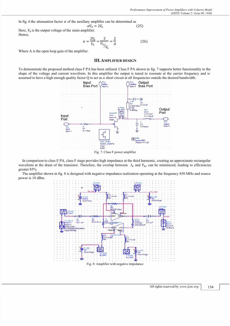
To demonstrate the proposed method class F PA has been utilized. Class F PA shown in fig. 7 supports better functionality to theshape of the voltage and current waveform. In this amplifier the output is tuned to resonate at the carrier frequency and isassumed to have a high enough quality factor Q to act as a short circuit at all frequencies outside the desired bandwidth.
Fig. 7: Class F power amplifier
In comparison to class E PA, class F stage provides high impedance at the third harmonic, creating an approximate rectangularwaveform at the drain of the transistor. Therefore, the overlap between and can be minimized, leading to efficienciesgreater 85%.
The amplifier shown in fig. 8 is designed with negative impedance realization operating at the frequency 850 MHz and source power is 10 dBm.
Fig. 8: Amplifier with negative impedance

7/21/2019 Performance Improvement of Power Amplifiers with Volterra Model
http://slidepdf.com/reader/full/performance-improvement-of-power-amplifiers-with-volterra-model 6/8
Performance Improvement of Power Amplifiers with Volterra Model (IJSTE/ Volume 2 / Issue 06 / 030)
All rights reserved by www.ijste.org 155
In order to realize the negative impedance, the auxiliary amplifier has been connected between the output and thecompensating impedance Configuration of whole circuitry is shown in Fig .8. As shown in [6,7], generally, when using thenegative impedance compensation the auxiliary amplifier may need not be highly linear as it is part of the negative impedancecircuit and handles small signal. This technique compares favorably with other two-path linearization methods where, in general,the linearizing signal path handles larger signal levels and therefore must itself be highly linear. Also, the auxiliary circuit can
perform satisfactory compensation in a large region with different .
IV. SIMULATION RESULTS
To demonstrate the proposed linearization technique Advanced Design System (ADS) software has been used. ADS is anelectronic design automation software system launched by Agilent EEsof EDA, a unit of Agilent Technologies. It provides anintegrated design environment to designers of RF electronic products such as mobile phones, pagers, wireless networks, satellitecommunications, radar systems and high speed data links.
Single Tone AnalysisA.
The simulation results of single tone analysis are discussed below with the help of graphical measurements.
Fig. 9(a) Fig. 9(b)Fig. 9: Output spectrum of the amplifier: (a) without linearization (b) with linearization
In fig. 9(a) and 9(b) from the output spectrum of the amplifier we can observe that with linearization the harmonics has become reduced in compared to without linearization. That means linearization has been achieved.
Fig. 10: (a) Fig. 10: (b)Fig. 10: 3rd and 5th order harmonic distortion: (a) without linearization (b) with linearization
The simulation result of fig. 10(a) shows that the 3 rd order harmonic starts at -51dBm and 5th order starts at -70 dBm. Toincrease the linearity, in the proposed method these values should be decreased than without negative impedance [8]. Fig.10(b)shows that the 3rd order curve starts from -140 dBm and 5th order starts from -230 dBm. Both the values are decreased withrespect to without negative impedance compensation . So, it proves that the simulation result with linearization improved andalso it reduces the harmonic distortion of amplifiers with the proposed technique.
Fig. 11(a) Fig. 11(b)Fig. 11: PAE, % analysis of the amplifier: (a) without linearization (b) with linearization
7/21/2019 Performance Improvement of Power Amplifiers with Volterra Model
http://slidepdf.com/reader/full/performance-improvement-of-power-amplifiers-with-volterra-model 7/8
Performance Improvement of Power Amplifiers with Volterra Model (IJSTE/ Volume 2 / Issue 06 / 030)
All rights reserved by www.ijste.org 156
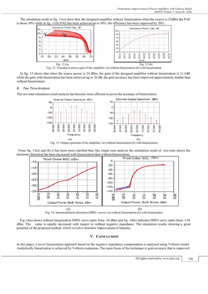
The simulation result in fig. 11(a) show that, the designed amplifier without linearization when the source is 23dBm the PAEis about 30% while in fig. 11(b) PAE has been achieved up to 50%, the efficiency has been improved by 20%.
Fig. 12 (a) Fig. 12 (b)Fig. 12: Transducer power gain of the amplifier: (a) without linearization (b) with linearization
In fig. 12 shows that when the source power is 24 dBm, the gain of the designed amplifier without linearization is 11.5dBwhile the gain with linearization has been achieved up to 20 dB, the gain accuracy has been improved approximately double thanwithout linearization.
Two Tone AnalysisB.
The two tone simulation result analysis has become more efficient to prove the accuracy of linearization.
(a) (b)Fig. 13: Output spectrum of the amplifier: (a) without linearization (b) with linearization
From fig. 13(a) and (b) it has been more clarified that, like single tone analysis the simulation result of two tone shows the
harmonic distortion has been decreased with linearization than without linearization.
(a) (b)Fig. 14: Intermodulation distortion (IMD) curves: (a) without linearization (b) with linearization
Fig.14(a) shows without linearization IMD3 curve starts from -34 dBm and fig .14(b) indicates IMD3 curve starts from -130dBm. The value is rapidly decreased with respect to without negative impedance. The simulation results showing a great
potential of the proposed method which reveals a dramatic improvement of linearity.
V. CONCLUSION
In this paper, a novel linearization approach based on the negative impedance compensation is analyzed using Volterra model.Analytically linearization is achieved by Volterra expansion. The main focus of the technique is gain accuracy that is improved.

7/21/2019 Performance Improvement of Power Amplifiers with Volterra Model
http://slidepdf.com/reader/full/performance-improvement-of-power-amplifiers-with-volterra-model 8/8
Performance Improvement of Power Amplifiers with Volterra Model (IJSTE/ Volume 2 / Issue 06 / 030)
All rights reserved by www.ijste.org 157
From single tone analysis gain accuracy successfully achived and PAE improved upto 20%. On the other hand nonlinearitycorrection of the main amplifier by using negative impedance that is realized by an auxiliary amplifier which is similar structureof main amplifier. The proposed method reduced third-order IMD component about 96 dBm on condition that PAs are excitated
by two-tone spacing above several MHz. However, as the two-tone spacing decreases, the reduced component is also decreased.If the spacing decreased to several hundred kHz, the third-order IMD component reduction will be very low . When the spacingis small enough to around a few kHz, the method have no longer any linearization effect. Also it has to be mentioned that thelinearity of third order IMD is about double than [9], there IMD component reduced 50 dBm. And the biggest advantage of thismethod is a high precision auxiliary amplifier is not needed. Finally, the simulation results show that high gain accuracy and
optimal linearity is achived by the propose linearization method.Future work of the research include using more accurate nonlinear analysis such as Monte-carlo method [5], Cartesian-Yingfeedback technique etc and optimizing the other critical parameters for RF/Microwave application. Also the overall system
performance like optimizing the power efficiency, low distortion, wide bandwidth and other critical parameters can be carriedout.
R EFERENCES
[1]
D. Bondar, N. D. Lopez, Z. Popovic and D. Budimir, “ Linearization of High Frequency Power Amplifier using Digital Baseband Pr edistortion withIterative Injection, “ In Proc. 2010 IEEE Radio and Wireless Symposium (RWS), New Orleans, LS, January 2010, pp. 148-151.
[2]
Piet Wambacq, Willy Sansen, Distortion Analysis of Analog Integrated Circuits. London.[3]
M. Faulkner,“Amplifier linearization using RF feedback and feedforward techniques,” IEEE Transactions on Vehicular Technology, vol. 47, no. 1, pp. 209-215, Feb. 1998.
[4]
B. Razavi, RF Microelectronics, Upper Saddle River, NJ: Prentice- Hall, 1998.[5] M. Tanseer Ali, Ruiheng Wu, Luhong Mao, Peter Callaghan, and Predrag Rapajic, “High frequency MOS Amplifier with Improved Lineari ty,” IET
Circuit, Devices and Systems.[6]
Wu, R., Lidgey, F.J., and Hayatleh, K.: ÒDesign of amplifiers with high gain accuracy and high linearityÓ, Proc. 50th IEEE International MidwestSymposium on Circuits and Systems, Montreal, Canada, August 2007, pp. 269-272
[7]
Wu,R., Lidgey, F.J., Hayatleh, K., and Hart, D0N0<"ÒDifferential amplifier with improved gain-accuracy and linearity, International Journal of CircuitTheory and Applications, 2010, 38, (10), pp. 829-844
[8]
Wu, R., Lidgey, F.J., Hayatleh, K.: „Design of amplifiers with high gain accuracy and high linearity‟. Proc. 50th IEEE Int. Midwest Symp. On Circuits and
Systems, Montreal, Canada, August 2007, pp. 269 – 272.[9] Zhixing Le Guojin Wan Limin Chen Xianghua Lu “Research on the Truncated Volterra Series Model for Shortwave Power Amplifiers Linearization “
China, 2009, pp 282-285.